


T30 SERIES PID Controller
User's Manual
DIGITAL PID CONTROLLER
SERIES
T30
PID controller + Timer
Hybrid

Useful Features !
※
Use the menu return function to speed up
the setting up to 10 times faster.
If you press the up key
while pressing the set key
in any setting menu,
you can move to the
corresponding upper menu
and move to the desired menu immediately.
+
F
u
n
c
t
i
o
n
o
f
m
e
n
u
r
e
t
u
r
n
sEt.n
< General Setting
group >
ORG.1
< Initial setting group >
iosE.2
< Input.output
Setting group >
Enhance hot key between
group menus

www.temcoline.com
DIGITAL PID CONTROLLER
Thank you for purchasing the T30 series from Temcoline.
The T30 series is a precision industrial controller that uses an advanced
2 degree-of-freedom (DOF) algorithm.
The T30 series consists of 5 models, which are T32, T33, T34, T37, and
T39.
This manual explains the installation, the functions, the operation, and
the handling of the products.
Please read the manual thoroughly before using the products.
If any difculties arise while using our products, please call our customer
service at +82-1588-5439.
- Use the products under the conditions specied in this manual.
- Please heed the cautions and warnings listed in this manual.
- The contents of the manual may be changed without notice.
- The product is designed to be used installed on a control panel.
- This manual is copyrighted, and may not be copied in part or in
whole without permission.
-
The manufacturer takes no responsibility for direct or indirect damages
caused by careless operation or operation under unpredictable or
risky environments.
Safety requirements are intended to prevent accidents and dangers
through the proper use of the products, so please heed them at all times.
The safety requirements are divided into "cautions" and "warnings",
which
indicate the following.
Serious injury or death may be caused
if instructions are not observed.
Failure to observe these instructions
may cause damage to the instrument
or some injury to the user.
2
Pay attention to the followings!
Safety requirements!
WARNING
CAUTION

www.temcoline.com
DIGITAL PID CONTROLLER
Use a separate safety device when this product is used to control a device
that could harm lives or expensive property in the event of a malfunction or a
breakdown. (This may cause res, deaths, or damage to property.)
Please conduct an inspection when water has entered the product.
(It may cause short circuits, res, and malfunction.)
Do not use this controller at place where there are flammable or
explosive gas. (It may cause a re or explosion.)
This controller should be used indoors.
(It may shorten the controller's life or give an electric shock.)
Before turning the power on, please check that wiring is correct to the
number of terminal. (It may cause a re.)
Observe the rated voltage and specication.
(It may cause a re or shorten the controller's life.)
Turn off the power during wiring and maintenance to avoid an electric shock.
Be careful that any of foreign materials do not inow into the controller. (It
may cause a re or malfunction of the controller.)
Do not touch the terminals when it is power on. (It may give an electric
shock.)
Do not give direct vibration or shock to the controller.
(It may cause of malfunction of the controller.)
This controller must be mounted on the panel to avoid an electric
shock.
Do not use chemical detergent or solvent, but use a dry towel in cleaning
the controller.(It may cause an electric shock or a re.)
Do not attempt to disassemble, modify and repair.
Please check the polarity of power before wiring and connecting the sensor. (It
may cause an electric shock or explosion.)
1.
1.
2.
2.
3.
3.
4.
4.
5.
5.
6.
6.
7.
7.
3
WARNING
CAUTION

www.temcoline.com
DIGITAL PID CONTROLLER
1. Ordering Information
2. Input ranges & Output conguration
3. Dimensions & Panel cutouts
4. Terminal Arrangements & Wirings
5. Ratings & Specications
6. Features & Function
7. Check points before using
8. Initial installation & Min. operation procedures
9. Entering into "set menu" & Setting method
10. Flow chart (Parameter structure)
11 . Setting mode
12. Alarm(ALARM1, 2, 3) setting
13. Details explanation of primary function
1) Auto tuning(AT) function
2) Manipulated variable(Mvn) check mode
3) Alarm(ALARM1, 2) function
4) Retransmission output
5) Input function
6) Selection function for Hysteresis
7) SV1, 2 set up control by external contact signal
8) Set value "LOCK" function
9) Error indication during operation
14. SOAK alam and Timer output
1) SOAK alam and Timer output
2) Timer Normal, T1~5 Output operation timing chart
5
16
28
9
18
30
32
14
27
22
7
17
29
12
27
21
31
32
32
32
32
33
15
27
25
Contents
4

www.temcoline.com
DIGITAL PID CONTROLLER
Code
Model
Code
2
3
4
7
9
S
Model
Code
Description
Size
Description
Remarks
Remarks
Remarks
T32-SERIES
SINGLE : Standard
Heating or Cooling control
T33-SERIES
T34-SERIES
T37-SERIES
T39-SERIES
48(W) x 96(H) x 77(D)
No option (Basic function)
No option (Basic function)
Option : 0, 1, 3
Option : 0, 3
No option (Basic function)
96(W) x 48(H) x 77(D)
96(W) x 96(H) x 77(D)
48(W) x 48(H) x 77(D)
72(W) x 72(H) x 77(D)
1. Ordering Information
1)
(1) Size
(3) Optional function
(2) Control mode
T32, T33
SERIES
T34
SERIES
T37
SERIES
T39
SERIES
0
RELAY output 1, Alarm output 2,
SCR(4~20mA), SSR(Voltage pulse) 1,
RET(4~20mA Retransmission output)
D.I(SV2, 3) External input
RELAY output 1, Alarm output 2,
SCR(4~20mA), SSR(Voltage pulse) 1,
RET(4~20mA Retransmission output)
D.I(SV2, 3) External input
RELAY output 1 (ALARM or MAIN),
SCR(4~20mA), SSR(Voltage pulse) 1
RELAY output 1, Alarm output 2,
SCR(4~20mA), SSR(Voltage pulse) 1
No function
(Basic function S0x)
No function
(Basic function S0x)
Basic function +
Option code
(0 : No option)
Basic function +
Option code
(0 : No option)
Ex.) T34-S10
Ex.) T34-S30
Ex.) T37-S30
RET(4~20mA Retransmission), Alarm 2
D.I(SV2, 3) External input, Alarm output 2
D.I(SV2, 3), RET(4~20mA Retransmission)
0
0
0
1
3
3
5
(1)
Size
(3) Optional function
(2) Control mode
(4) Power supply voltage
T 3 -

www.temcoline.com
DIGITAL PID CONTROLLER
Code
0
1
Description
Remarks
100 ~ 240 V AC
Alternating or Direct current usage
General-purpose usage
24V AC or DC
2) Example of model building
(4) Power supply voltage
6
"4"
"S"
"0"
"0"
T34-S00
"7"
"S"
"3"
"0"
T37-S30
Ex.) T34-S00
Ex.) T37-S30
(1)
Size : 48(W) x 48(H) x 77(D)
(1)
Size : 72(W) x 72(H) x 77(D)
(3) Optional function : Basic function
(3) Optional function : DI(SV1,2), RET
(2) Control mode : SINGLE
(2) Control mode : SINGLE
(4) Supply voltage : 100~240V AC
(4) Supply voltage : 100~240V AC
www.temcoline.com
DIGITAL PID CONTROLLER
2. Input ranges and Output configuration
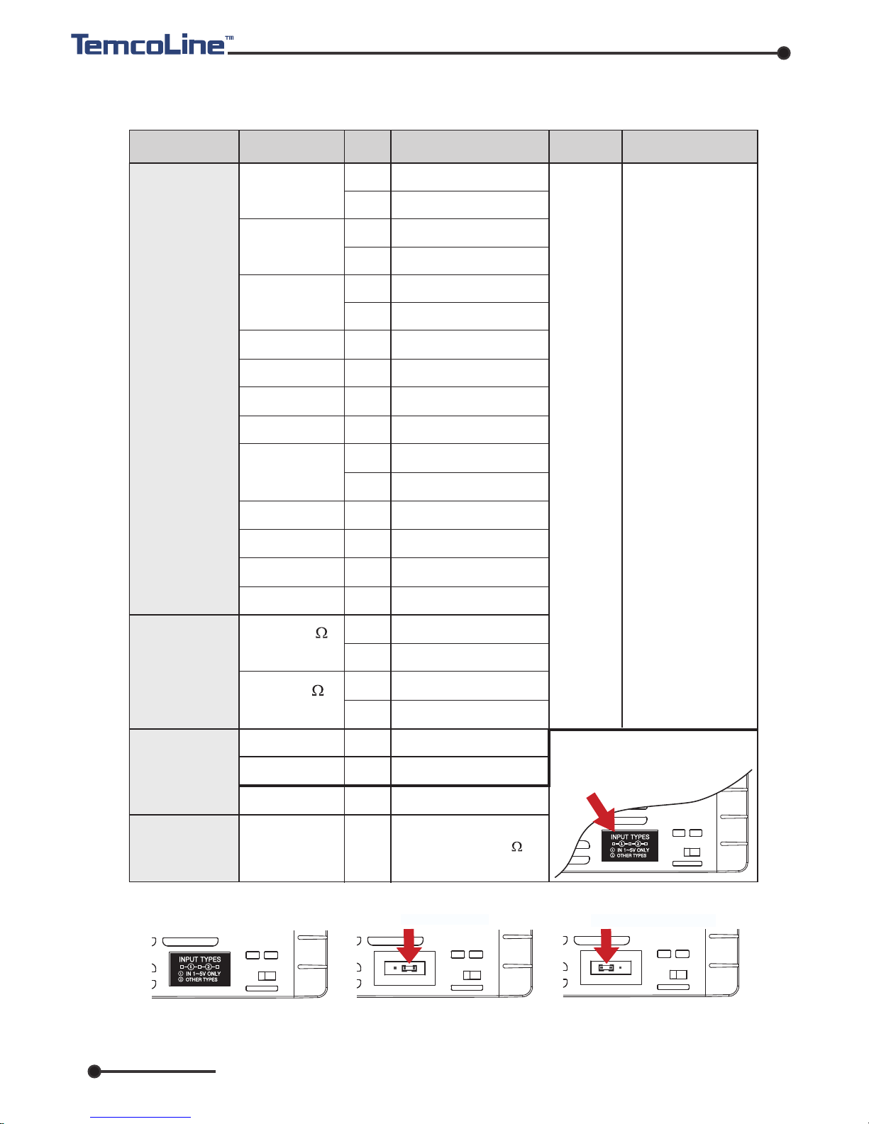
1) Input ranges
※ The T30 series has multiple inputs, which may be set and changed by the user.
7
※ How to change the interior switch when using 1~5V input
* F.S is max. value
to min. value of
each range.
* Digit is minimum
of display.
K
J
E
T
R
B
S
L
N
U
C (W5)
D (W3)
0~100 mV DC
-10~20 mV DC
1~5 V DC
4~20 mA DC
1
2
15
16
3
4
5
6
7
8
17
9
10
12
13
20
22
21
23
33
32
30
30
11
±0.3% of
F.S + 1 Digit
Voltage
(V DC/mV DC)
-200 ~ 1370
-199.9 ~ 999.9
-200 ~ 1000
-199.9 ~ 999.9
-200 ~ 1000
-199.9 ~ 999.9
-199.9 ~ 400.0
0 ~ 1700
400 ~ 1800
0 ~ 1700
-200 ~ 900
-199.9 ~ 900.0
-200 ~ 1300
-199.9 ~ 400.0
0 ~ 2300
0 ~ 2400
-199.9 ~ 500.0
-200 ~ 500
-199.9 ~ 640.0
-200 ~ 640
0 ~ 100 mV DC
-10 ~ 20 mV DC
1~5 V DC
When using current input,
use the resistor 250 on
input terminal.
Input type
Input
Setting
Code
Temperature range
Remarks
Accuracy
Thermocouple
(T.C)
RTD
Current
※ When using 1~5V input
(30), the interior jumper
switch must be relocated.
①
Remove plate or take out
the main cover.
②
Move and insert the
jumper that pulled by
tweezers.
③
Relocated jumper as
above and attach plate
or mounted cover.
MULT-IN MODE
IN 1~5V ONLY MODE
JPt100
(JIS, KS)
Pt100
(DIN, IEC)

www.temcoline.com
DIGITAL PID CONTROLLER
2) Output
conguration
(1) Summary and explanation of output settings
General
type
Setting
number
OUTPUT-1
OUTPUT-1 (ALARM 1,2)
T30-SXX
0
1
2
3
Relay output
SSR output
AL1 output AL2 output
SSR/SCR OUTPUT
SCR output
SCR output
OUT(ON/OFF)
ALM3(ALM1)
ALM3(ALM1)
ALM3(ALM1)
ALARM1 ALARM2
RET
RET
RET
RET
-
-
-
-
ALM3(ALM1)
OUT(PID)
OUT(PID)
OUT(PID)
※
The gure on the left uses
the terminal socket of
T37-S30 as an example
to illustrate the output
response relationship
.
Relay output of ON/OFF control [ Output setting number : 0 ]
This is a simple on/off control, mainly used to control cooling devices.
SSR output of PID control (Voltage pulse) [ Output setting number : 1 ]
This is the most widely used setting, and the default value at the point of manufacture.
SCR output of PID control (4~20mA current output) [ Output setting number : 2 ]
This setting is used mainly with thyristor power regulator (TPR) modules,
and is capable of precision control.
Relay output of PID control [ Output setting number : 3 ]
This is the most cost-efcient method of implementing PID control and is used mainly
with magnetic switches (electric switches). However, it may wear the contact point,
and is difcult to use in places that require fast response.
1(SSR) or 2(SCR)
0(ON/OFF)
or 3(RELAY)
Control output
Control output
The T30 series
has multiple outputs.
8
※ It is only for T34-S00!
ALARM1 or
3 output
ALARM1 or
3 output
(2) Main relay control output and alarm output
The T30 series can use up to three alarms independently when using the control
output as SSR (1) or SCR (2). That is, the basic model (no option) can be used as
alarm 1, and the optional model (alarm output) can be used as alarm 3.

www.temcoline.com
DIGITAL PID CONTROLLER
3. Dimensions and Panel cutouts
1) T32 (48x96 mm) Dimensions
2) T33 (96x48 mm) Dimensions
3) T34 (48x48 mm) Dimensions
9
T32 / T33 (96x48)
Panel cutouts
(Unit: mm)
(Unit: mm)
45
±0.5
92
±0.5
Min. 30
Min. 20
T34 (48x48) Panel cutouts
Min.17
Min.17
45
+0.5
-0
45
+0.5
-0
48.0
96.0
10.0 77.0
96.0
91.0
96.0
48.0
48.0
43.6
10.0
77.0
8.8
48.0
44.9
48.0
77.0
48.0

www.temcoline.com
DIGITAL PID CONTROLLER
4) T37 (72x72 mm) Dimensions
5) T39 (96x96 mm) Dimensions
10
(Unit: mm)
(Unit: mm)
T37 (72x72) Panel cutouts
Min. 20
68
±0.5
68
±0.5
Min. 30
T39 (96x96)
Panel cutouts
Min. 20
92
±0.5
92
±0.5
Min. 30
72.0
9.0 77.0
72.0
67.0
72.0
96.0
77.0
96.0
91.0
10.0
96.0
 Loading...