

Temco VFL34RN, VFL34RP, VFL34MN, VFL34MP Installation And Operating Instructions Manual
Installation and Operating
Instructions for Gas Log
Heaters
Models: VFL34RN, VFL34RP
Models with “N” after the model number use natural gas; models with “P” after the model number use propane (LP) gas.
READ AND SAVE THESE INSTRUCTIONS
This appliance operates as an unvented room
heater certified under ANSI Z21.11.2-2000 when
fitted to a solid fuel burning masonry or factory
built fireplace with the flue damper closed. It also
operates as a decorative appliance under ANSI
Z21.60a-2000.CSA 2.26a-2000, when fitted to a solid
fuel burning masonry or factory built fireplace with
the flue damper open. When used as a decorative
appliance, the use of a thermostat is not allowed.
State or local codes may only allow operation of
this appliance in a vented configuration. Check
your state or local codes.
WARNING
If the information in this manual is not followed exactly, a fire or explosion may result causing
property damage, personal injury or loss of life.
FOR YOUR SAFETY
—Do not store or use gasoline or other flammable vapors and liquids in the vicinity of this or
any other appliance.
WHAT TO DO IF YOU SMELL GAS
• Do not try to light any appliance.
• Do not touch any electric switch; do not use any phone in your building.
• Immediately call your gas supplier from a neighbor's phone. Follow the gas supplier’s instruc-
tions.
• If you cannot reach your gas supplier, call the fire department.
—Installation and service must be performed by a qualified installer, service agency or the gas
supplier.
This is an unvented gas-fired heater. It uses air (oxygen) from the room in which it is installed. Provisions
for adequate combustion and ventilation air must be provided. Refer to Section Provisions For Adequate
Combustion and Ventilation Air - Page 4.
Gas Fired
Unvented
Room Heaters
Temco Fireplace Products
410 Admiral Blvd. • Mississauga, Ontario, Canada L5T 2N6 • 905-670-7777
5L24
78570 11/03 Rev. 6
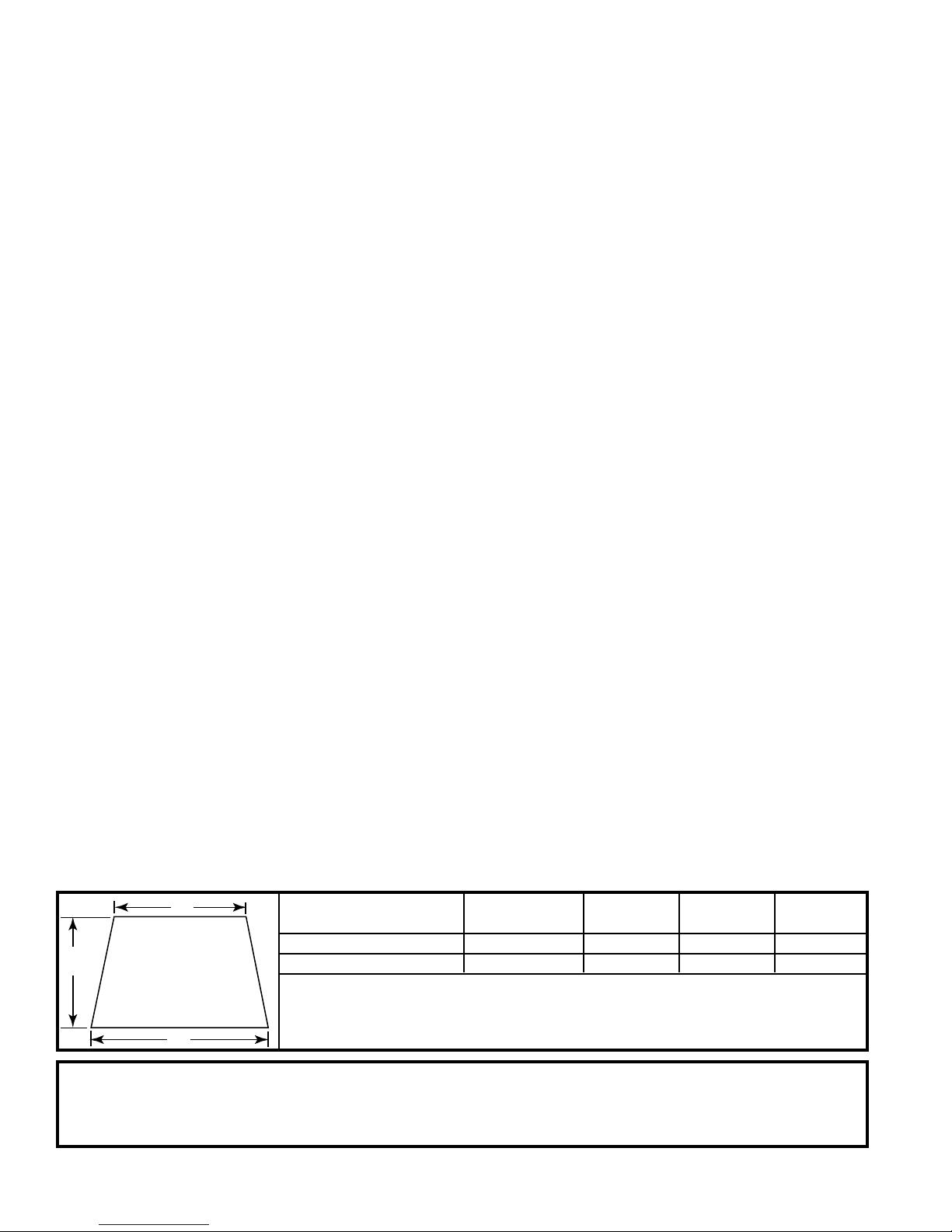
Table of Contents
Minimum Dimensions for Existing Solid Fuel Burning Fireplaces ............................................2
Important Information ...............................................................................................................3
Provisions For Adequate Combustion Air .................................................................................4
Installation
Unpacking.................................................................................................................................6
Fireplace Preparation ...............................................................................................................6
Location ....................................................................................................................................6
Clearances ...............................................................................................................................6
Gas Connection........................................................................................................................7
Typical Gas Line Connection....................................................................................................8
Gas Line Pipe Sizing ................................................................................................................9
Gas Pressure Check.................................................................................................................9
Log Assembly .........................................................................................................................10
Fireplace Screen ....................................................................................................................10
Millivolt System Control Options ............................................................................................. 11
Remote Control Information ...................................................................................................11
Lighting Instructions................................................................................................................12
Turning Off Gas to Appliance..................................................................................................12
Important Safeguards .............................................................................................................13
Match Lighting ........................................................................................................................13
Flame Check...........................................................................................................................13
Managing Heat Output ...........................................................................................................14
Maintenance
Cleaning..................................................................................................................................14
Troubleshooting..........................................................................................................................15
Servicing ......................................................................................................................................15
Repair Parts .................................................................................................................................16
Warranty Information..................................................................................................................17
Installation and Startup Checklist .............................................................................................18
Warranty Registration.................................................................................................................20
Minimum Dimensions for Existing Solid Fuel Burning Fireplaces
B
Hearth Size Table (H) (A) (B) (C)
C
Opening Height = H
A
This appliance may be installed in an aftermarket, permanently located, manufactured (mobile) home, where not
prohibited by local codes.
This appliance is only for use with the type of gas indicated on the rating plate. This appliance is not convertible for
use with other gases.
2
Opening Height Front Width Rear Width Depth
VFL34RN 17” 26” 21” 11”
VFL34RP 17” 26” 21” 11”
78570
Important Information
INSTALLER: Please leave these instructions with the
owner.
OWNER: Please retain these instructions for future
reference.
WARNING: Any change to this heater or its controls can be dangerous.
IMPORTANT: READ THESE INSTRUCTIONS CARE-
FULLY BEFORE INSTALLING.
NOTES
• Due to high temperatures, the appliance should be
located out of traffic and away from furniture and draperies.
• Installation and repair should be done by an experienced
and qualified service person or gas appliance installer.
• The appliance must be inspected before use and at least
annually by a professional service person. More frequent
cleaning may be required due to excessive lint from
carpeting, bedding material, dust and pet hair, etc. It is
important that the control compartment, burners and
circulating air passageways of the appliance be kept clean.
Refer to instructions on Page 14.
• DO NOT place clothing or other flammable material on or
near the appliance.
• This appliance must only be used with pressures at the inlet
as shown in Table 1, page 9. Failure to check and document
these pressures may void the warranty.
• The installation must conform with local codes or, in the
absence of local codes, with the NATIONAL FUEL GAS CODE,
ANSI Z223, latest edition. If you cannot reference these codes,
DO NOT attempt to install this unit.
• Any safety screen or guard removed for servicing an
appliance must be replaced prior to operating the heater.
• The appliance and its appliance main gas valve must be
disconnected from the gas supply piping system during any
pressure testing of that system at test pressures in excess of
1/2 psig (3.5 kpa).
• The appliance must be isolated from the gas supply piping
system by closing its equipment shut-off valve during any
testing of the gas supply piping system at test pressures equal
to or less than 1/2 psig (3.5kpa).
• DO NOT use this heater in recreational vehicles, bedrooms or
bathrooms.
• If this is the ONLY gas appliance, we recommend a
minimum 200 pound cylinder with a fill gauge. Use of a 100
pound cylinder is not recommended. Other household gas
appliances may require the tank size to be larger. Do not
operate the vent-free heater if the fuel level in the propane
tank is below 1/4 full.
• DO NOT use this heater if any part of it has been submerged
under water. Immediately call a qualified technician to inspect
the appliance and replace any part of the control system and
any gas control which has been under water.
• Any outside air ducts in the fireplace shall be permanently
closed at the time of appliance installation.
• Check local, state or city codes to determine if unvented
heaters are permitted. If unvented heaters are not permitted, the fireplace chimney damper must be fixed at a
minimum free (vent) opening area of 15 sq. ins. This must
be accomplished by a clamp or screw on the chimney
damper to stop at the minimum vent area. The fireplace
must also have a minimum free (vent) opening of 15 sq.
ins. (Fig. 1)
• This appliance may be installed in an after-market* manufac-
tured "mobile" home where not prohibited by state or local
codes.
*After-market: Completion of sale, not for purpose of re-sale
from the manufacturer.
• OUTSIDE AIR DAMPER OR ASH DUMP (IF PRESENT)
MUST BE CLOSED AND SEALED.
• Young children should be carefully supervised when they
are in the same room as the appliance.
WARNING: Do not allow fans to blow directly into
the fireplace. Avoid any drafts that alter burner
flame patterns.
WARNING: Do not use a blower insert, heat exchanger
insert or other accessory not approved for use with this
heater.
WARNING: During manufacturing, fabricating and
shipping, various components of this appliance are
treated with certain oils, films or bonding agents. These
chemicals are not harmful but may produce annoying
smoke and smells as they are burned off during the
initial operation of the appliance, possibly causing
headaches and eye/lung irritation. This is a normal and
temporary occurrence.
WARNING: This appliance is for installation only
in a solid-fuel burning masonry or UL 127 factorybuilt fireplace or in a listed ventless firebox enclosure. It has been designed certified for these
installations. Exception: DO NOT install this
appliance in a factory-built fireplace that includes
instructions stating it has not been tested or
should not be used with unvented gas logs.
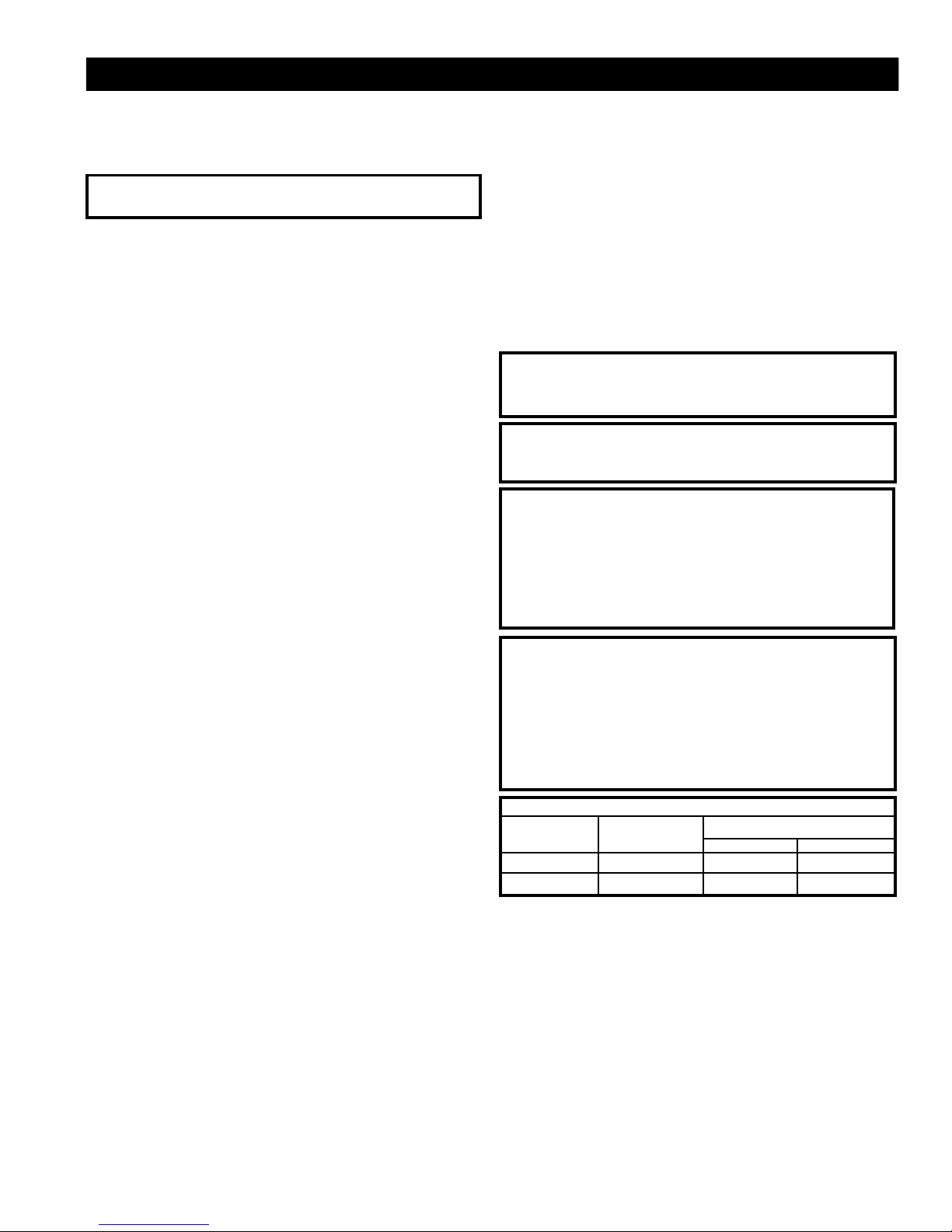
Input (BTU/hr)
BTU/hr
Model Fuel Hi Lo
VFL34RN Natural 34,000 22,000
VFL34RP LP/Propane 34,000 25,500
• An unvented room heater having an input rating of more
than 10,000 btu per hour shall not be installed in a bedroom
or a bathroom.
For Installation of High Altitude
When installing this fireplace at an elevation above 2,000 feet
(in the United States), it may be necessary to decrease the
input rating by changing the existing burner orifice to a smaller
size. Input should be reduced four percent (4%) for each 1,000
feet above sea level, unless the heating value of the gas has
been reduced, in which case this general rule will not apply. To
identify the proper orifice size, check with the local gas utility.
Consult your local gas utility for assistance in determining the
proper orifice for your location.
78570
3

Provisions for Adequate Combustion and Ventilation Air
WARNING: This heater shall not be installed in a
confined space or unusually tight construction unless
provisions are provided for adequate combustion
ventilation air.
The National Fuel Gas Code, ANSI Z223.1
defines a
confined space as a space whose volume is less
than 50 cubic feet per 1,000 Btu per hour (4.8m3 per
kw) of the aggregate input rating of all appliances
installed in that space and an unconfined space as a
space whose volume is not less than 50 cubic feet
per 1,000 Btu per hour (4.8 m3 per kw) of the aggregate input rating of all appliances installed in that
space. Rooms communicating directly with the
space in which the appliances are installed, through
openings not furnished with doors, are considered a
part of the unconfined space.
Today's homes are built more energy efficient than ever. New
materials, increased insulation and new construction methods
help reduce heat loss in homes. Home owners weather strip
and caulk around windows and doors to keep the cold air out
and the warm air in. During heating months, home owners
want their homes as airtight as possible.
While it is good to make your home energy efficient, you need
fresh air. All fuel-burning appliances need fresh air for proper
combustion.
Supplying Adequate Ventilation
This appliance must be installed in an unconfined space.
The following information will help you classify your space
and provide adequate ventilation for complete combustion.
An Unconfined Space has a minimum volume of 50 cubic
feet for each 1000 BTU/Hr input rating of all appliances in the
space. (4.8 M
height of space).
A Confined Space has a volume of less than 50 cubic feet
for each 1000 BTU/Hr input rating of all appliances in the
space, (4.8M3 per kw), (cubic feet equals length x width x
height of space).
3
per kw), (cubic feet equals length x width x
Determining if You Have a Confined or
Unconfined Space
Use this worksheet to determine if you have a confined or
unconfined space.
Space: Includes the room in which you will install heater plus
any adjoining rooms with doorless passageways or ventilation
grills between the rooms.
1. Determine the volume of the space (length x width x
height).
Length x Width x Height = _____cu. ft. (volume of space)
Example: Space size 25’ (length) x 25’ (width) x 8’ (ceiling
height) = 5,000 cu. ft. (volume of space)
If additional ventilation from adjoining room(s) is supplied
with grills or doorless openings, add the volume of these
rooms to compute the total volume of the applicable
space.
2. Divide the space volume by 50 cubic feet to determine the
maximum BTU/Hr the space can support.
________(volume of space) ÷ 50 cu. ft. = (Maximum BTU/
Hr the space can support.
Example:
or 100,000 (maximum BTU/Hr the space can support)
3. Add the BTU/Hr of all gas burning appliances in the space.
Example:
*Do not include direct-vent gas appliances. Direct-vent draws
combustion air from the outdoors and vents to the outdoors.
4. Compare the maximum BTU/Hr the space can support
with the actual amount of BTU/Hr used.
__________ BTU/Hr (maximum the space can support)
__________ BTU/Hr (actual amount of BTU/Hr used)
Example:
used)
The space in the above example is an unconfined space
because the actual BTU/Hr used is less than the maximum
BTU/Hr the space can support. If the space had been
confined, your options would be as follows:
A. Rework worksheet, adding the space of an adjoining
B. Install a lower BTU/Hr heater, if lower BTU/Hr size
5,000 cu. ft. (volume of space) ÷ 50 cu. ft. = 100
Gas range BTU/Hr
Vented gas heater BTU/Hr
Gas fireplace logs BTU/Hr
Other gas appliances* +
Total = BTU/Hr
Gas range 60,000 BTU/Hr
Vent-free logs +
Total = 89,000 BTU/Hr
100,000 BTU/Hr (max. the space can support)
89,000 BTU/Hr (actual amount of BTU/Hr
room. If the extra space provides an unconfined
space, remove door to adjoining room or add ventilation grills between rooms. See Ventilation Air From
Inside Building.
makes room unconfined.
BTU/Hr
29,000 BTU/Hr
Converting Confined Space to Unconfined
Space
Additional volume to convert a confined to an unconfined
space could come from an adjoining space. When using an
adjoining space, you can provide two permanent openings:
one within 12" of the ceiling and one within 12" of the floor on
the wall connecting the two spaces (see options 1 and 3,
Figure 2), or remove the door into the adjoining room.
Ventilation Air From Outdoors for Unusually Tight Construction
WARNING: If the area in which the heater may be
operated is smaller than that defined as an unconfined
space or if the building is of unusually tight construction,
provide adequate combustion and ventilation air by one
of the methods described in the National Fuel Gas Code,
ANSI Z223.1/NFPA 54, Section 5.3 or applicable local
codes.
4
78570
Unusually tight construction is defined as construction
where:
a. walls and ceilings exposed to the outside atmosphere have
a continuous water vapor retarder with a rating of one perm
(6 X 10.11 kg per pa-sec-m2) or less with openings gasketed
or sealed and
b. weather stripping has been added on openable windows
and doors and
c. caulking or sealants are applied to areas such as joints
around window and door frames, between sole plates and
floors, between wall-ceiling joints, between wall panels, at
penetrations for plumbing, electrical and gas lines and at
other openings.
If your home meets all of the three criteria above, you must
provide additional fresh air.
You may provide two permanent openings: one within 12" of
the ceiling and one within 12" of the floor. Connect these items
directly to the outdoors or spaces open to the outdoors. These
spaces include attics and crawl spaces. Follow the
National
Fuel Gas Code NFPA 54/ANSI Z223.1, Section 5.3, Air for
Combustion and Ventilation
for required size of ventilation grills
or ducts.
IMPORTANT: Do not provide openings for inlet or outlet air into
attic if attic has a thermostat-controlled power vent. Heated air
entering the attic will activate the power vent.
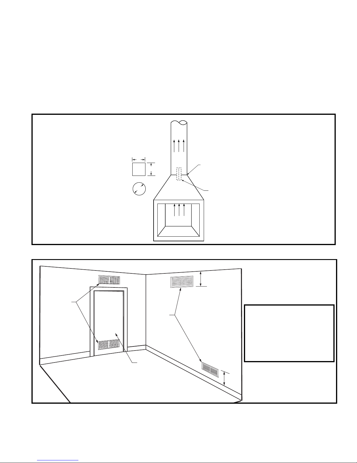
L
W
D
NOTE: For round flue opening,
minimum flue diameter (d) = 5”. For
square or rectangular opening,
length x width (L x W) must equal 15
sq. in.
Fig. 1 Minimum flue diameter and flue damper positions.
Option 1 Vents to
Adjoining
Room
Option 3 Vents to
Adjoining
Room
Option 2 Remove
Door to
Adjoining
Room
Flue Damper Closed for Unvented
Operation and Maximum Heat
Output
Flue Damper Locked Open
to a Minimum Free (Vent)
Opening of 15 sq. in., (for
areas where unvented
products are not permitted)
12”
WARNING: Air openings that
provide fresh air from an adjoining unconfined space shall not be
blocked or obstructed in any way.
Installation of unit should allow a
minimum of 2" clearance from any
part of the heater to any of the
ventilation openings.
12”
T104
Fig. 2 Ventilation options for confined space.
78570
VO370-2
5

Installation
Unpacking
Open the carton and remove the logs and the chassis. Remove each of the logs by gripping at either end of the log while
avoiding any undue pressure. Please note that the logs have
been marked for positive identification.
The carton for all models contains the following: grate/burner
assembly, front and rear logs, 2 top twigs, 2 screws, a bag of
volcanic ash and a bag of embers.
Fireplace Preparation
The fireplace needs to be prepared before installing the unit:
A. Turn off the gas supply if the gas line has been run to the
fireplace.
B. WARNING: Before installing logs in fireplace, the
chimney flue and firebox must be cleaned of soot,
creosote, ashes and loose paint by a qualified chimney
cleaner or sooting will occur.
Note: If your fireplace has been cleaned using chemicals or
solvents, these products may have been absorbed into the
fireplace hearth and walls and will be burned off during the
initial break-in period.
C. Any outside air ducts and/or ash dumps in the fireplace shall
be permanently closed and sealed at the time of appliance
installation. This will prevent drafts from disturbing the
flames and interfering with complete combustion of the gas
fuel.
Location
When gas logs are to be installed in a fireplace, inspect the
area surrounding it for possible air drafts that may affect the
flames and possibly cause sooting. Such drafts may be caused
by a ceiling fan near the fireplace, a hot air furnace register or
an open door. When burning the logs, carefully observe the
effect of possible drafts on the flames and take appropriate
measures to eliminate them. For example, the ceiling fan may
be cut off, the hot air register closed, etc.
Centrally locate the gas logs in the fireplace deep enough into
the firepit to accomplish an adequate draft (if use as a vented
appliance is planned). Ensure that the front feet of the grate sit
inside the front edge of the fireplace. Be sure fireplace meets
minimum fireplace dimensions.
To avoid any movement of the unit during operation, screw
the chassis to the floor of the fireplace using the screws
provided. Failure to do so could cause gas leaks.
Holes are provided in the sheet metal chassis (Fig. 3) and
should be used for securing the log set. After locating the
chassis correctly in the fireplace, mark the hole positions on the
fireplace floor. Drill two 1/8” diameter holes approximately 1/2”
deep.
Use the two screws to secure the chassis to the fireplace floor.
(Fig. 3)
Clearances
NOTE: The following instructions regarding installation clear-
ances and the use and installation of a canopy apply to use of
the appliances as an unvented space heater in permitting
jurisdictions. When installed as a vented decorative gas
appliance, the clearances noted below and the use of a heatdeflecting canopy are not required.
However, it is recommended that these instructions be followed
even when the appliance will be used as a vented decorative
appliance in case local codes change to allow unvented space
heaters or in the event that the flue damper is inadvertently
closed.
Clearances for unvented installation in existing fireplaces,
(jurisdiction permitting)
1. Sidewall Clearances: Clearances from the side of the
fireplace opening to any combustible wall should not be less
than 2”. (Fig. 4A and 4B)
2. Ceiling Clearances: The ceiling height should not be less
than 62" from the top of the fireplace opening. (Fig. 4A)
3. Mantel Clearances: The use of a canopy* is optional
depending on mantel clearances to the fireplace opening
and projection profile.
NOTE: Mantel clearances may differ for each vent-free
firebox. Refer to the firebox installation instructions for
clearances.
A. Mantel profile: The minimum distance above the
fireplace opening to combustible material projecting 1¹⁄₂"
(tile moldings, breast boards, etc.) is 12¹⁄₂".
Combustible material projecting 6" (a mantel shelf, for
example) requires a minimum clearance of 19" above the
fireplace opening. Required clearance varies with the
amount of projection. (Fig. 4C)
The mantel profile must fall within the cross-section
shown in Figures 4C or 4D.
B. Heat resistant material: Any heat resistant material
suitable for a continuous operating temperature of 120°C
(248°F) must cover the wall surface directly above the
fireplace opening and extend the full width of the
fireplace opening for a distance of 10" above the
opening. (Fig. 4C)
T131a
Fig. 3 Use two (2) screws to secure the chassis to the fireplace
floor.
6
78570
 Loading...