


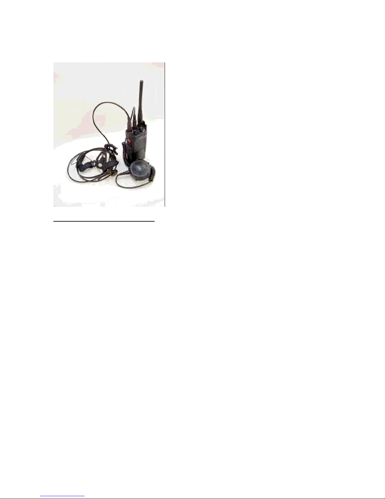
V.A.D.E.R.
VOICE-ACTIVATED DIGITALLY ENHANCED RADIO
PROFESSIONAL SECURE RADIO SYSTEM
USER’S MANUAL
SR390, SR450

CONTENTS
ABOUT THE AV.A.D.E.R. SYSTEM 1
FEATURES 2
INSPECTION 3
NAME OF PART&CONTOROLS 4
BATTERY INSTRATION (REPLACE) 5
MONITOR 8
EMERGENCY 8
SET-UP 12
OPERATION 14
PTT 14
VOX 14
NOISE CANCEL PTT 14
NOIZE CNACEL VOX 14

Notice to SR390/SR450 User
"This wireless portable device has been shown to be capable of compliance for localized specific
absorption rate (SAR) for uncontrolled environmental/general population exposure limits specified in
ANSI/IEEE Std. C95.1-2005 and has been tested in accordance with the measurement procedures
specified in FCC/OET Bulletin 65 Supplement C (2002) and IEEE Std. 1528-2003. SAR Compliance for
body-worn operation is based on a separation distance of 1.4 cm between the rear of the unit and the
body."
ABOUT THE V.A.D.E.R. SYSTEM
The V.A.D.E.R. communication system was developed for professional use in mobile communications
within a small group that has tasks requiring high confidentiality. To secure the communication, the
V.A.D.E.R. radio features a scrambling transmission along with a high-speed frequency scanning that
makes group's communication hard to be intercepted.
The RF output power is selectable between LO (200mW) and HI (2W) according to the group's range of
activities. Minimizing the RF output power prevents detection and interception from outside of the
group.
The V.A.D.E.R. radio does not come with a built-in microphone or a speaker. You can use this radio by
connecting the external audio device either a Headgear or an Ear Microphone both applies Temco's bone
conduction technology. Neither the Headgear nor the Ear Mic prevents you from wearing a helmet.
Furthermore, neither device sets its microphone near your mouth. The system's complete face-free
configuration assists your active tasks.
A remarkable feature of the V.A.D.E.R. radio is to have the DSP (Digital Signal Processor) that makes
VOX (Voice Activation) work steadily even in highly noisy condition. This achieved to offer the
enhanced VOX that first meets the tasks of professional communications. The DSP activates the VOX
circuitry only when the input signal is recognized as the human voiced sounds, and switches the radio to
the transmit mode.
The DSP also enables to temporarily store the speech on memory and send them to transmit with a slight
delay.
This completely prevents clipping the voice syllable at the beginning of speech that the conventional
VOX currently in use could never achieve. You can also enjoy the noise cancellation function featured
by the DSP that suppresses noise elements through digital processing and creates the clear audio to
transmit. Along with Temco's noise-resistant bone conduction microphones, the higher the ambient noise
level is, the more you can feel its excellent performance.
The Radio Housing is made from aluminum alloy that allows the unit to be light but sturdy.
An easy detachable battery housing is made from reinforced polycarbonate resin that resists against heat
and shock. You can use rechargeable battery coming with original kit. Or replacement of regular type
AA battery clip (BC390) is also available in Temco’s variety of optional products. You can use world

wide common style of six AA (SUN-3) dry batteries or AA (SUN-3) sized rechargeable cells into the
battery clip (BC390) .
Both the radio transceiver and the battery pack are submersible. You can use the V.A.D.E.R. radio under
any weather conditions in outdoors.
The V.A.D.E.R. secure radio system is the most suitable equipment for professional tasks requiring high
security and confidentiality.
FEATURES
Hands-free, Face-free
Waterproof, submersible radio (in 6.5 feet / 30 minutes)
Waterproof Headgear HG17CN-T and Body PTT Switch BP210
Enhanced DSP VOX. No clipping the speech. No miss-operation by ambient noise.
DSP noise canceling
Channel Hopping (High speed channel scanning)
Scrambling transmission
Emergency signal alerting function
Small & light-weight, no user adjustment required
INSPECTION
When you receive your packaged V.A.D.E.R. system, inspect the shipping carton for any signs of
damage. Then, remove and check the contents of the packing case to be certain that all items ordered
have been included.
Contents of the packing case may be different from those listed below if optional accessories were
ordered.
Standard kit Optional accessories
1. Radio Transceiver SR390 / SR450
2. Antenna AT390 / AT450
3. Rechargeable Battery Pack BC390
4. Battery Charger BP390
5. AC Adopter AD-M12-2000
6. User’s Manual (this manual)
Optional accessories
1. Headgear HG17BN-T
2. Body PTT Switch BP210
3. Ear Mic EM7-05
4. Programming Cable CA01A-01
5. Cloning Cable CA02A-01
6. Programming Software CD02-01
7. Headset with Boom Mic HG30CN-T
8. Remote Speaker Mic RSM220-T
9. Battery Clip for regular AA cell BC390

* One of the following an Antenna is enclosed in the package according to the preset frequencies as
below.
AT390 for 380-446MHz,
AT450 for 446-512MHz,
** No battery cell is enclosed in the BC390. Prepare 6pcs of AA Alkaline battery for starting to use the
system.
Inspect the equipment thoroughly. If any part of the equipment has been damaged in transit, report the
extent of the damage to Temco Japan Co., Ltd., or Temco Communications, Inc. immediately.
NAME OF PART & CONTROLS
①. V.A.D.E.R. radio transmitter/receiver
②. Headgear
③. Ear Mic
④. Body PTT Switch
⑤. PTT Button
⑥. Monitor/ Emergency Button
⑦. Latch Lever
⑧. Battery Clip
⑨. Battery Housing
⑩. Battery Cap
⑪. Clamp
⑫. Antenna Connector
⑬. Program Connector
⑭. AF Connector

⑮. Water-seal Plug
⑯. Power/Volume Switch
⑰. RF Output Power Selector
⑱. Mode Selector Switch
⑲. Group Selector Switch
BATTERY INSTALLATION (OR REPLACEMENT)
(OR REPLACEMENT)
Please follow as following instruction 1,2, and 7 with original rechargeable battery pack.
Please follow for whole procedure with optional battery clip (BC390).
1. Press and hold the 2 Latch Levers on the side of Radio
Housing at the same time and pull down the Battery Clip to
remove from the Radio Housing.
2. Release the Clamp located at both sides of Battery Cap by
using the right hand side of Latch Lever on the Radio
Housing.
Remarks: The left hand side of Latch Lever is wider than the right
hand side, so it is not convenient to use for releasing the Clamp.
3. Pull the Battery Cap to remove from Battery Housing.
4. Insert 6 cells of fresh AA Alkaline battery in the Battery Housing.
Remember to install the batteries with correct direction of polarity
as shown on the figure.

Caution: DO NOT use Manganese battery.
5. Align the Battery Cap and Battery Housing and press down until the Cap is firmly seated in the
Housing.
Caution: Ensure that the O-ring gasket on Battery Clip and inside of Battery Housing is clean.
Sticking of
dirt on this area may cause improper performance of waterproof.
6. Fasten the Clamps at both sides of Battery Cap and ensure being tightly closed by hearing “click”.
7. Align the Battery Clip and Radio Housing (recessed grooves along the right hand side of Radio
Housing and
Battery Clip are to be linked) and press in the Battery Clip to the Radio Housing. The Latch Levers
guide a
right positioning of Battery Clip to the Radio Housing. Ensure to firmly attach the Battery Clip on to the
Radio Housing by hearing “click!” at both Latch Levers.
Remarks: The Battery Clip cannot be attached if it is aligned at the opposite side to the Radio Housing.
Caution: Ensure that the O-ring gasket on Radio Housing and inside of Battery Cap is clean.
Sticking of dirt on this area may cause improper performance of waterproof.
Warning: DO NOT THROW AWAY THE USED BATTERIES INTO FIRE. Please dispose the
used
batteries in ecological manner.
FUNCTIONING METHOD OF V.A.D.E.R. SR21 RADIO
The SR390/450 radio has multiple programmable functions such as Simplex, Semi-Duplex, Channel
Hopping, Scrambling, setting of Priority Channel, setting of CTCSS, time-out-timer, etc. by using
optional programming software. Refer the details on separate Programming Manual.
up to the highest level.
1. The SR390/450 radio has programmable frequencies in 1-16 Groups. When the radio is to be
programmed for use in Semi-Duplex operation, the Tx frequency is set on TX FREQ. and the Rx
frequency is set on RX FREQ.. When the radio is programmed for use in Simplex operation, the
same frequency is to be set on both TX FREQ. and RX FREQ. In Group #16 (in other words,
position #16 at the Group Selector Switch), the Emergency signal alerting frequency is to be
programmed. The frequency for Priority channel can also be set in this Group #16.

2. When the radio is powered ON by turning the Power/Volume Switch to clockwise. When any
frequency programmed on Group #16 for Emergency alerting signal or for Priority channel, the
radio also receive the carrier wave on this frequency.
3. When the carrier wave is detected on one of the destined frequencies, the radio immediately stops
scanning to recognize the CTCSS and compares it with the radio’s preset CTCSS. If the CTCSS in
the received carrier wave coincides with the preset CTCSS of the radio, squelch is opened and the
radio is engaged in the Receive mode. If no CTCSS is detected, or if the detected CTCSS does not
coincide with the radio’s preset CTCSS, then the radio keeps on scanning the destined frequencies
between Group# and #16(Emergency).
Caution:
the radio receives.
If the CTCSS is programmed “None”, the squelch can be opened for any carrier wave that
4. Monitor/Emergency button provides either of the following function. You need to select to assign
the function as Monitor or Emergency.
Monitor ….. Short pressing of Monitor/Emergency button By short pressing of Monitor/Emergency
button (less than 2 seconds), the radio opens the squelch and receives the carrier waves in
transmission on the channel where the scanning stops. This is to be used for checking whether the
channel is open or in use.
Emergency ….. Long pressing of Monitor/Emergency button by prolong pressing of
monitor/Emergency button (more than 2 seconds), the radio keeps on transmitting the Emergency
alerting signal until the Power Switch is turned OFF. The Emergency alerting signal can be selected
from 10 types of tones and duration/interval is also programmable.
Important: While the Emergency alerting signal is being transmitted, the Mic line of SR390/450
radio is also in active, so that you can override your message over the alerting tone for letting a
Group member know of your location and emergency message. For facilitating this function, it is
important that the duration of alerting tone transmission should be programmed to hold sufficient
time for enabling to transmit the massage at the same time. While any one of the SR390/450 radio in
a Group is transmitting the Emergency alerting signal, all other radios in the same Group coinciding
the CTCSS are kept on capturing the signal (and message), and are unable to communicate with
others. For not blocking the Group’s communication, it is important that the interv al of Emergency
alerting signal should be programmed to hold sufficient time for enabling other radios in a Group to
maintain the communication for the rescue order in the interval of
Emergency alerting tone. The default setting of signal interval is 5 seconds.
5. When PTT Button is pressed, or when the radio PTT is triggered by VOX, channel scanning is
immediately stopped and the operator can hear a short “Pip!” tone via his speaker of Headgear or
Ear Mic for letting him know that his transmission becomes established. If the existing carrier wave
from other transmission is detected in that frequency, no Ready-to-Tx tone as “Pip!” is heard, and
Tx status cannot be engaged. In this case, release the PTT Button for making the radio restart to scan
the channels, and press the PTT Button once again, or make voiced sound again after 0.7 second in
VOX mode, to catch the “open” channel.
Remarks: Engaging the Tx status by neglecting the existence of other carrier wave in air can be
programmed.
6. When PTT Button is released, or when the radio is turned to Receive/Stand-by status by no
detection of voiced sounds to trigger the VOX, the Mic line is to be OFF and send the
End-of-Transmit signal for indicating to terminate transmission. When the Tx status is disengaged,
the operator can hear a short “Pip! Pip!” tone via a speaker of Headgear or Ear Mic for letting him

know that his transmission is now terminated, and the radio returns to scan the channels for
receiving.
Caution:
If the Tx status keeps on engaging for more than 30 seconds*, the transmission is
automatically shut off and the radio returns to scan the channels for receiving. (*programmable
factor)
7. On the radios that have been receiving the message, the channel scanning is restarted when they
receive the End-of-Transmit signal. If the radio(s) can not, or failed to, receive the End-of-Transmit
signal, the channel scanning starts after 2.5 seconds* from the end of carrier wave being tuned in.
(*programmable factor)
8. When the Group #16 is selected by Group Selector Switch, the radio can be used as conventional
simplex two-way transceiver by simple PTT or VOX operation on this channel. This function can be
used for All Call of all radios in a Group.
9. To inactive particular Group(s) for Tx/Rx can be programmed though the frequencies are
programmed on all Groups’ channels. When the Group Selector Switch selects the inactive Group #,
the operator hears alerting signal as “Poop, Poop” for letting him know that the Group selected is
out of order.
10. When the battery runs low (voltage detection), the operator can hear short alerting tone such as
“Pu!, Pu!” for letting him know that the battery replacement is on order. When this tone is heard,
replace the battery immediately.
Remarks: This Low Battery alerting tone can be heard only in the Transmit status and may be
resumed in the Receive/Stand-by status. This is due to high current consumption required for
transmission. In any status when the Low Battery alerting tone is heard, it is requested to replace the
battery.
SET-UP
1. Hands tighten the Antenna by turning it clockwise on to the Antenna Connector on the top panel of
radio.
Caution:
There are 2 types of Antenna depending on the frequency bandwidth programmed on the SR21
radio.
#1:AT390 for 380-446MHz
#2:AT450 for 446-512MHz
Be sure to use the right Antenna for optimizing the performance. Use of wrong Antenna will make
insufficient coverage of communication area, and may cause malfunction of radio due to excessive load
put on the transmitter.
2. Mate the key guide of audio connector of Headgear or Ear Mic with the AF Connector (6 pin) on the
top panel of radio and press in. Turn the Lock Screw clockwise until it is firmly tightened.
3. If required, unscrew (turn counterclockwise) and take off the water-sealed cap on the Program
Connector (7 pin) on the top panel of radio, and mate the key guide of the audio connector of Remote
PTT Switch and press in. Turn the Lock Screw clockwise until it is firmly tightened.
Caution:
Be sure to securely tighten the Antenna and all other audio connectors on right
position. Insufficient tightening of Antenna and connectors may cause improper
performance of waterproof.

4. Put the Headgear or Ear Mic on position.
Caution:
Maker a better contact of Microphone and Speaker of Headgear to your head. Loose
contact may cause insufficient audio performance as like deterioration of microphone sensitivity
or low audio volume from the speakers. When Ear Mic is used, remember to select the ear tip
either Medium or Large for your comfortable fit to your ear, and insert the earpiece as deep as
possible into your ear canal. Loose contact of Ear Mic to your ear may cause insufficient audio
performance as like deterioration of microphone sensitivity or lack of intelligibility in transmit
audio.
Caution:
Ear Mic is NOT waterproof. DO NOT use in the water or under heavy rain or splash of
water.
OPERATION
1. Select the communication mode as appropriate for your operation.
Operation Mode: PTT
Function: Either PTT Button on the radio or Remote PTT Switch connecte d to the radio is
being in function.
Operation Mode: VOX
Function: Built-in VOX is being in function. The transmission is automatically keyed on
by your speech. Your message is sent with slight delay at 0.5 sec for avoiding
clipping of the first part of speech. PTT operation via PTT Button on the radio or
Remote PTT Switch remains in function.
Operation Mode: NOISE CANCEL
Function: Either PTT Button on the radio or Remote PTT Switch connecte d to the radio is
being in function. Digital noise suppression is added on the transmit signals. This
DSP controlled noise cancellation is to selectively suppress the audio elements that
are not being recognized as human voiced sounds. Due to this digital processing, a
slight deterioration of audio quality is observed.
Operation Mode: NOISE CANCEL VOX
Function: Built-in VOX is being in function. The transmission is automatically keyed on by
your speech. Your message is sent with slight delay at 0.5 sec for avoiding clipping
of the first part of speech.
Digital noise suppression is added on the transmit signals. This DSP controlled noise
cancellation is to selectively suppress the audio elements that are not being
recognized as human voiced sounds. Due to this digital processing, a slight
deterioration of audio quality is observed. PTT operation via PTT Button on the
radio or Remote PTT Switch remains in function.
2. Select the RF output power between Hi (2W) and Lo (200mW) by RF Output Power Selector
according to the Group’s range of activity.
3. Select the Group number by Group Selector Switch where your communication is to be established.
4. Power the radio ON by turning the Power/Volume Switch clockwise, and set the volume level at 12
o’clock position. You can adjust the volume level as appropriate for your operation.
5. In PTT operation, press and hold on the PTT Button on the radio, or press and hold on the Remote
PTT Switch, to engage Transmit status for sending your message. Release the PTT Button, or
Remote PTT Switch, to return in Receive/Stand-by status.
6. In VOX operation, start to speak in normal voice to automatically engage the Transmit status. If the

VOX circuitry detects no voiced sound for 0.7 sec, it shuts off the transmission an d makes the radio
return to Receive/Stand-by status.
Caution: When the radio is engaged in Transmit status, you can hear a short “Pip!” via a speaker
of Headgear or Ear Mic. Remember that your transmission is not completed if no “Pip!” tone is
heard.
In this case, release the PTT Button (in PTT operation) or mute your speech more than 0.7 sec (in
VOX operation) to make the radio return in Receive/Stand-by status, and retry to press the PTT
Button or start speaking for establishing the transmission. Especially in VOX operation, you
should always aware of “Pip!” tone for starting speech and “Pip! Pip!” tone for ending the
transmission.
 Loading...