

TEMCO FIREPLACE PRODUCTS, Inc.
Click here to print
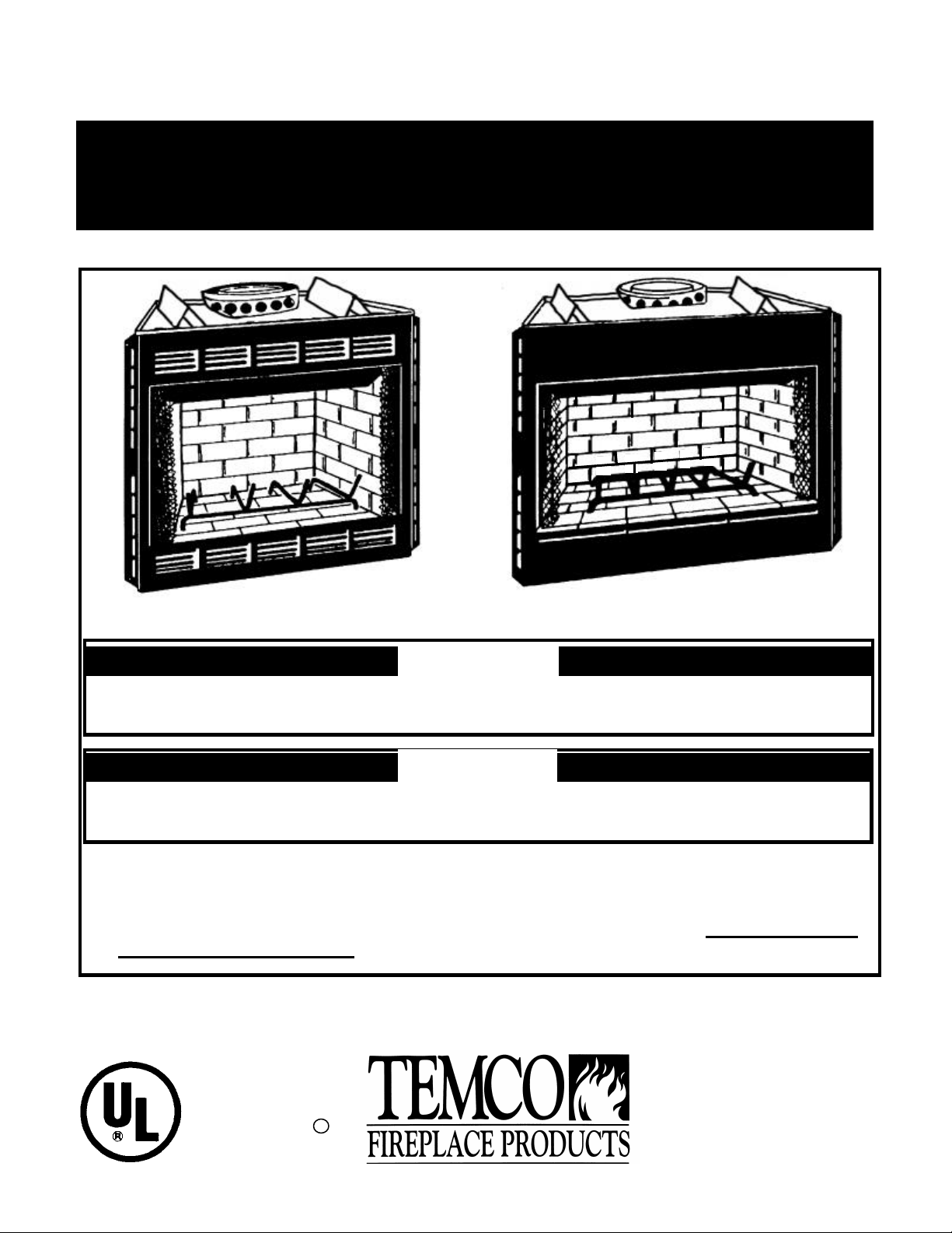
Installation and Operating Instructions for Low Profile, Front-Opening,
Wood -Burning Fireplaces - Models Listed for use in Manufacturing Housing
Models TLC42-4MB, TLC36-3MB, TFC36-3M AND TLC36-3MBE
READ AND SAVE THESE INSTRUCTIONS
TLC Series Louvered Heat Circulating Fireplace
TFC Flush Face Fireplace
WARNING
THIS FIREPLACE HAS NOT BEEN TESTED WITH AN UNVENTED GAS LOG SET. TO REDUCE
RISK OF FIRE OR INJURY, DO NOT INSTALL AN UNVENTED GAS LOG SET INTO FIREPLACE.
WARNING
If the information in this manual is not followed exactly, a fire or explosion may result causing
FOR YOUR SAFETY
− Do not store or use gasoline or other flammable vapors and liquids in the vicinity of this or
any other appliance.
− Installation and service must be performed by a qualified installer. Do not attempt to
install this fireplace yourself!
P.O. Box 1349 Manchester, TN 37349
P.O. Box 1148 Perris, CA 92572
Underwriters
Laboratories Inc. R
File MH10105
1773 Parque Industrial Cachanilla
Mexicali, B.C. 21600
REV. 8/13/02 1:44 PM 76834K

CONTENTS
Introduction ......................................................................................................................................................................................................2
TEMCO Chimney System .......................................................................................................................................................................3
Basic Rules ................................................................................................................................................................................................3
Model with Listed Features and Accessories .......................................................................................................................................3
Planning Ahead
Choosing the Location for Your Fireplace ............................................................................................................................................4
Outside Air Kit and Glass Door Accessories ........................................................................................................................................5
Gas Line .....................................................................................................................................................................................................5
Drafts ..........................................................................................................................................................................................................5
Locating the Flue Pipe .............................................................................................................................................................................5
Chimney Outlet .........................................................................................................................................................................................5
Firebox and Chimney System Clearances ........................................................................................................................................5,6
Determining the R-Values .......................................................................................................................................................................6
Fireplace Installation
Installing the Firebox .............................................................................................................................................................................7,8
Installing the Chimney ..............................................................................................................................................................................8
10 Foot Rule of Thumb ............................................................................................................................................................................9
Offset Installations .........................................................................................................................................................................9,10,11
Installing a Gas Line ...............................................................................................................................................................................12
Insulation of the Fireplace Enclosure ..................................................................................................................................................12
Finishing Your Fireplace ......................................................................................................................................................................13,14
Using Your Fireplace ...................................................................................................................................................................................15
Replacement Parts .......................................................................................................................................................................................16
Warranty ..........................................................................................................................................................................................................17
Warranty Registration .................................................................................................................................................................................18
Warranty - Glass Doors ...............................................................................................................................................................................19
Warranty - Blower .........................................................................................................................................................................................20
INTRODUCTION
This book contains your installation instructions and should
be kept in a safe place. It will be a handy reference guide
to operating your fireplace after installation. For you to
realize all the advantages and use of the reliable service
that has been engineered into your TEMCO fireplace, you
must carefully follow all of the instructions contained in this
book regarding installation and operation of the fireplace.
These instructions should be read carefully in their entirety
before beginning installation of the fireplace.
ONCE THE FIREPLACE HAS BEEN INSTALLED, THE
SECTION “USING YOUR FIREPLACE”, FOUND ON
PAGE 14 OF THIS MANUAL, SHOULD BE REVIEWED IN
ITS ENTIRETY PRIOR TO OPERATING THE
FIREPLACE.
It is suggested that you wear work gloves and safety
glasses to protect your hands and eyes when installing your
fireplace.
NOTE: Authorities having jurisdiction (i.e. building
inspectors, fire marshals, etc.) should be consulted before
installation to determine the need to obtain a permit.
All models are listed for use in residential and/or
manufactured housing construction in the United States
with a TEMCO double-wall 8" diameter air-cooled chimney
and the components listed below.
BE SURE TO FOLLOW EXACTLY THE SPECIFIC
INSTALLATION RESTRICTIONS THAT APPLY TO THE
MODEL YOU ARE INSTALLING. The model number of the
fireplace is located on a label behind the firescreen inside
the front of the fireplace.
Listed in the United States by Underwriters Laboratories,
Inc., #MH10105, ICBO Report AA-668/TL-157, SBCCI
Report #8809, BOCA Report #87-31.
2
8" Diameter Double Wall Chimney System
Chimney Sections Other Chimney Components
8212D 12" Section SC1215-1 Storm Collar
8218D 18" Section 8232E 30° Elbow Set
8224D 24" Section 8204F-1 90° Firestop Spacer
8236D 36" Section 8230F-1 30° Firestop Spacer
8248D 48" Section 8206F 0 - 6/12 Roof Flashing
8212F 7 - 12/12 Roof Flashing
8203D Round Termination Cap
BEFORE YOU BEGIN ...A FEW BASIC RULES
1. The instructions on the following pages were designed to
make the installation of your TEMCO fireplace as quick
as possible. It is important that they be followed. This
fireplace is to be installed only by a qualified installer.
2. Use only TEMCO manufactured components, listed
under 8" Diameter Chimney System when installing a
TEMCO fireplace. Substituting other manufacturers'
components for, or altering TEMCO parts will void
the UL listing and the TEMCO warranty.
3. Check local building codes for restrictions which may not
be contained in this manual.
4. The fireplace design permits installation and framing
adjacent to combustible materials. Do not set the
fireplace on vinyl flooring or carpets.
? COMBUSTIBLE MATERIALS MUST NOT OVERLAP
THE SURFACE OF THE BLACK FRONT FACE
PANELS. COMBUSTIBLES MAY BE INSTALLED
OVER THE SIDE NAIL FLANGES UP TO THE EDGE
OF THE FRONT FACE SURFACE.
5. ALL CHIMNEY SECTIONS, ELBOWS AND FLUE
SUPPORTS REQUIRE AN ABSOLUTE MINIMUM OF
1" AIR SPACE CLEARANCE TO ALL
COMBUSTIBLES.
6. The minimum distance from the fireplace opening to an
adjacent combustible wall is 15½". See page 6 for
alternative wall shields and required R-factors.
7. If the floor in front of the fireplace is combustible, a
protective hearth extension must be used. Raised or
floor level extensions may be constructed. On flush face
models only, a raised hearth extension may be flush with
the fireplace hearth. For a raised hearth on louvered
models, the fireplace must also be installed on a
platform.
? Minimum hearth dimensions: 36" models 16" x 52"
42" models 20" x 66"
? Since many hearth extension materials are not insulating
materials, a layer of noncombustible inorganic insulating
material must be used also. See pages 6 and 7 for Rfactor requirements.
8. Adhere to the 10' Rule of Thumb for chimney height,
(see page 9).
9. Chimney supports:
a. Flue support is required for every 35' of vertical system
height.
b. Flue support is required for every 6' of offset chimney.
c. Guy wire stabilizer is required for chimneys extending
more than 6' above roof line.
10.Only TEMCO model glass doors (see chart below) may
be installed on these fireplaces.
11.The barometric damper on the Combustion Air Kit allows
air to be drawn from above, below or behind the
fireplace; but air must never be drawn from the attic or
garage spaces. Refer to the air kit installation manual for
complete installation and use information. The AK-18 Air
Kit is designed to be installed through the floor of the
home. The inlet duct should be located below the
framing and insulated flooring materials, and
communicate wit h a free air space.
12.Check your local building code to determine if grounding
is required and what procedure should be followed.
Grounding is recommended by the manufacturer if you
live in an area of high risk due to electrical storms.
13.System specifications: See Fig. 10 through 15.
14.On louvered models, which have a factory installed
blower or fan kit, it is necessary to bring a power source
to the fireplace. See separate installation instructions.
See BL-1 blower instructions for wiring procedures.
15.READ THE COMPLETE MANUAL BEFORE
BEGINNING THE INSTALLATION OF THE FIREPLACE.
WARNING: Do not install a fireplace in a sleeping
Models with Features and Accessories
MODEL FACE/OPENING DOORS FAN OUTSIDE COMBUSTION AIR KIT JUNCTION BOX
TLC42-4MB louvered 42" x 21 7/8" CX-61 BL-1 AK-18 JB-2
TLC36-3MB louvered 36" x 21 7/8" CX-21 BL-1 AK-18 JB-2
TLC36-
3MBE
TFC36-3M flush 36” x 21 7/8 CX-21 N/A AK-18 - - -
louvered 36" x 21 7/8" CX-21 BL-1 AK-18 JB-2
3
PLANNING AHEAD
CHOOSING THE LOCATION FOR
THE FIREPLACE:
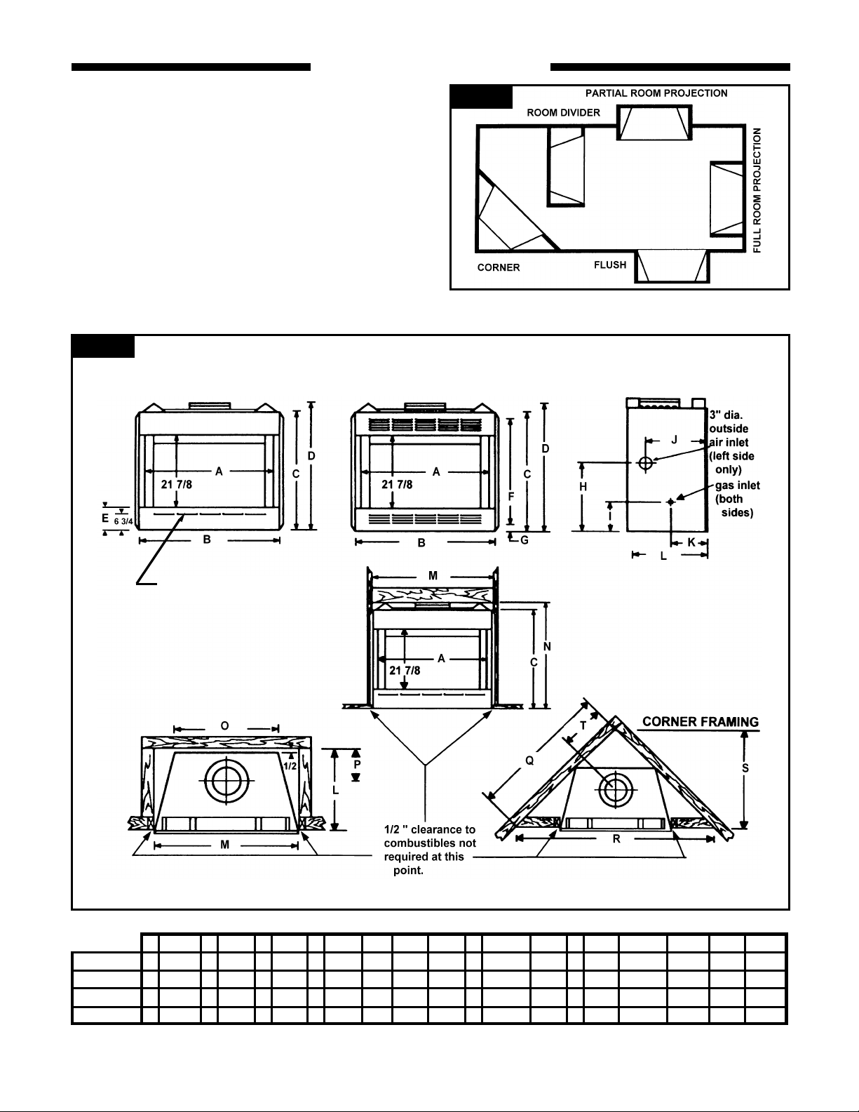
Figure 1 shows some of the many ways the fireplace may
be installed. Consider the traffic pattern in the room and
location door s and windows. A corner location may be best
where space is limited.
The fireplace weighs no more than common furniture . If the
fireplace is located near a load bearing wall, additional
supports to the foundation will not be necessary.
HEAVY FACINGS SUCH AS SOLID BRICK, STONE,
ETC., MAY REQUIRE ADDITIONAL FOUNDATION
SUPPORT.
ALTHOUGH THIS UNIT MAY BE INSTALLED ON
COMBUSTIBLE SURFACES, IT MUST NOT BE
Figure 2
Fireplace and Framing Dimensions (inches)
Figure 1
TLC42-4MB ONLY
A B C D E F G H I J K L M N O P Q R S T
TLC36-3MB 36 38 1/2 35 37 3/4 7 31 1/4 2 12 1/8 8 5/8 15 1/2 9 21 38 3/4 38 1/4 22 8 7/8 46 65 32 1/2 14 3/8
TLC36-3MBE
TLC42-4MB 42 44 9/16 39 41 1/2 8 33 3 17 9 3/4 18 10 1/2 22 44 13/16 41 3/4 32 8 1/2 54 76 1/4 38 1/8 17 5/8
TFC36-3M 36 38 1/2 35 37 3/4 7 N/A - 12 1/8 8 5/8 15 1/2 9 21 38 3/4 38 22 8 7/8 46 65 32 1/2 14 3/8
36 38 1/2 35 37 3/4 7 31 1/4 2 12 1/8 8 5/8 15 1/2 9 21 38 3/4 38 1/4 22 8 7/8 46 65 32 1/2 14 3/8
4

OUTSIDE AIR KIT AND GLASS DOOR
ACCESSORIES
A fireplace needs a steady supply of air in order to draw
properly. Many houses and apartments which are well
sealed lack sufficient air for normal operation. IN SUCH
HOUSES, IT IS RECOMMENDED THAT A COMBUSTION
AIR KIT BE INSTALLED. A combus tion air kit will improve
the efficiency of any fireplace, especially if used in
conjunction with glass doors, because it allows you to use
outside air for combustion instead of heated room air.
Installing the fireplace on an outside wall will simplify the
installation of the combustion air kit and reduce the amount
of necessary duct work. Install the air kit according to the
separate installation instructions packed with it. If an air kit
is to be installed, IT MUST BE INSTALLED AT THE TIME
THE FIREPLACE IS INSTALLED, before its enclosure is
finished.
The fireplace includes an integral barometric damper. The
control lever is located on the left side behind the mesh
screen.
GAS LINE
If you plan to install a gas line, it must be installed at the
time of framing the fireplace. The gas line must be installed
in accordance with local codes. See p.12 for installation
instructions.
DRAFTS
The location for the fireplace should be away from objects
such as frequently opened doors and central heat air outlets
and inle ts that will create drafts and possibly hamper the
normal flow of air into the fire.
LOCATING THE AREA WHERE THE FLUE
PIPE WILL PASS THROUGH THE CEILING
AND THE ROOF
It is very important that you determine where the flue
(chimney) will go through the ceiling and roof. Check the
structure of yo ur home to see that the location you have
chosen will make installation as easy as possible. Using a
plumb bob, hold the string from the ceiling and drop it,
moving the string until the plumb bob is in the center of the
flue collar opening, (see figure 3). Mark the spot on the
ceiling. You may wish to drive a nail through the ceiling at
this spot. Then go into the attic and find the nail. Using the
plumb bob with the ceiling nail as the center point of the
flue, mark the center of the area on the roof through which
the flue will pass. This is to see if it is possible to cut your
opening for the flue in both the ceiling and roof without
cutting either roof rafters or ceiling joists. A location that
requires cutting the least number of joists and rafters will
simplify the installation and reduce the cost. The structural
integrity of a home's floor, walls, ceiling and roof must be
maintained. It is not recommended to cut roof trusses.
CHIMNEY OUTLET
Thought should be given to the proposed location of the
chimney outlet on the roof. Objects such as trees, adjacent
buildings or embankments that are too close to the chimney
can create air circulation problems during windy weather
that could affect the way the fireplace draws air.
After careful consideration, choose the location for your
fireplace to achieve the simplest installation for maximum
efficiency.
FIREBOX AND CHIMNEY SYSTEM
CLEARANCES
The fireplace may be placed directly on a combustible floor,
against a combustible wall at marked clearances or on a
Figure 3
raised wooden platform.
If the fireplace is to be installed on a raised platform, the
platform must be a continuous level surface.
The fireplace must be secured in place so it cannot shift
positions. The nailing flanges on the sides of the firebox
make securing the firebox to the frame quick and easy. The
nailing flanges were designed to allow the installation of
1/2" wallboard or plywood flush with the face of the
fireplace.
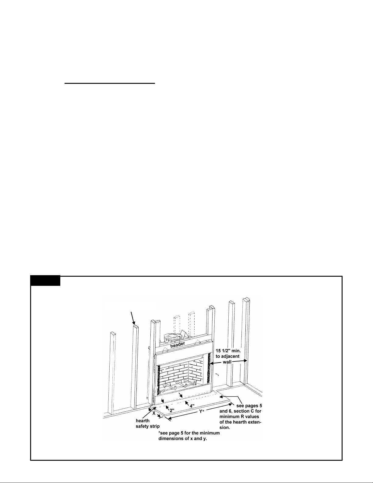
Only the header (see figure 4) may rest on the standoffs on
top of the firebox.
Combustible materials may not cover any part of the black
metal surrounding the firebox opening. See figure 4.
Do not install the firebox over vinyl floors or carpet.
Combustible floors in front and to the sides of the firebox
opening must be protected by a noncombustible hearth
extension as shown in figure 4.
THE CAUTIONS BELOW RELATE TO LOCATIONS ON
FIGURE 4, (letters on pictures correspond with items
below).
A. When installing the hearth extension, a protective
1) The pre-fabricated hearth extension (or site built) must
2) After the fireplace and hearth extension have been
(OR)
If a protective metal strip is used under the space between
the fireplace and hearth extension, sealing of the gap
between the fireplace and hearth extension is optional.
B. COMBUSTIBLE MATERIALS MUST NOT OVERLAP
THE SURFACE OF THE BLACK FRONT FACE
PANELS. COMBUSTIBLES MAY BE INSTALLED
OVER THE SIDE NAIL FLANGES UP TO THE EDGE
OF THE FRONT FACE SURFACE.
Use of the Plumb Bob
metal satety strip is not required below the front
face of the fireplace and mating edge of the hearth
extension if the followi ng steps are taken:
be secured to the floor of the home to prevent shifting.
Various methods of attachment may be used including
screws, nails, or common construction adhesives.
secured, the gap between the fireplace and hearth
extension must be filled or sealed with a noncombustible grout, caulk, or sealant.
5
C. If the floor in front of the fireplace is combustible, either a
raised or floor-level protective hearth extension must be
constructed. For flush-face models only, a raised hearth
extension may be flush with the fireplace hearth. To
construct a raised hearth extension with louvered
models, the fireplace must rest on a raised platform. A
raised hearth extension must have minimum dimensions as
follows:
X Y
36" models 16" 52"
42" models 20" 66"
? and be constructed of materials with an R-factor equal to
or greater than 1.20.
? A hearth extension installed directly on the floor must be
a minimum of 16" x 52" and be constructed of materials
with an R-factor equal to or greater than .80. If
combustible materials are used to construct the hearth
extension, they must not touch the black surface of the
fireplace. The same material that is us ed to protect the
top of the hearth extension must be placed between the
combustible hearth and the black face of the fireplace.
The hearth extension must be fastened to the floor to
prevent shifting and the gap between the fireplace and
the hearth extension must be sealed with a noncombustible material (400 0 F. min) if a metal safety strip is not
used. These materials (listed below) may be used for a
wall shield as well.
D. The framing header may rest on top of the standoffs.
E. The minimum distance from the fireplace opening to an
adjacent combustible wall is 15½". The minimum
distance to an adjacent combustible wall may be reduced
to 12" when an approved wall shield is used on the wall.
The wall shield must be 40" x 40" and be constructed of
a noncombustible, inorganic material having a thermal
resistance of R = 1.49.
Figure 4
Determining the R-Values
The hearth extension must be constructed of noncombustible materials which have a total thermal resistance
(R factor) equal to or greater than .80 for floor level hearth
extensions or 1.20 for raised hearth extensions and be a
minimum size as shown in the table on page 5. Choose the
desired materials and obtain the K value at 75° mean
temperature. The C value and the R value may be
calculated with the following formulas:
K = Thermal conductivity. K = BTUs-ins./hrs.-ft.2-0F
T = thickness C= Thermal conductance
R = Thermal resistance K/T = C; 1/C = R
Example: 3/4" Marble with 3/8" Micore
Determine the R value for each material used as follows:
Marble:K/T= 11/.75=14.66.
1/C = 1/14.66 = 0.068 (R factor)
Micore 300: K/T = .458/.375 = 1.22.
1/C = 1/1.22=0.82 (R factor)
After the R value is obtained on each material in this hearth,
add the R values to obtain total thermal resistance (R).
Total R factor = 0.068 + 0.82=0.89
The total must be equal to or greater than specified above.
Typical materials: Micore 300 has a K of .458; Micore 230 has a
K of .43; Micore 180 has a K of .34; Ceraboard has a K of .34;
common brick has a K of 5; cement mortar has a K of 5; marble
has a K of 11; limestone has a K of 6.5; tile has a K of 12; slate
has a K of 21; Wonder Board has a K value of 3.2.
MICORE NC 180-300, manufactured by U.S. GYPSUM
CORPORATION
CONWED SPEC 300, manufactured by CONWED
CORPORATION
CERA FORM TYPE 106R board, manufactured by
JOHNS-MANVlLLE.
WONDER BOARD, manufactured by GOLD BOND
Framing Members
6

FIREPLACE INSTALLATION
This list of specific instructions will help you make certain
that every installation operation is done correctly. Complete
the installation steps in the sequence shown.
Local building codes should be consulted in all cases as to
the particular requirements concerning the installation of
factory built fireplaces. Select the location for the fireplace
by taking into consideration the factors previously outlined
in the Planning Ahead section of the manual.
TLC36-3MB, TFC36-3M and TLC42-4MB fireplaces are
Underwriters Laboratories listed for installation in a
manufactured (mobile) home with TEMCO double-wall 8”
air-cooled chimney and components.
TEMCO glass doors, firestop thimble, and Model AK-18
combustion air kit must be installed for manufactured
(mobile) home use. The duct for the combustion air kit may
go through the floor or the side wall of the home. A BL-1
Blower Accessory is factory installed on louvered circulator
models only.
See Figure 10 for min imum system height. The height of
the system is measured from the base of the fireplace and
includes 6” of the chimney cap.
Figure 5 Framing Dimensions
INSTALLING THE FIREBOX
STEP 1. FRAMING THE FIREBOX
When framing the opening for the fireplace, make certain
that the header is the correct height above the surface upon
which the fireplace will sit. The header must be level. The
header and framing may be installed as shown in figure 5 or
figure 7 according to the installer's preference.
The entire fireplace can be elevated above the floor to
achieve a raised hearth effect. This can be done by adding
a small platform to achieve the desired height.
The nailing flanges on the side of the firebox were designed
to allow the installation of ½" wallboard or plywood flush
with the face of the firebox. Metal floor tabs are provided to
secure the fireplace to the floor of the home.
STEP 2. HEARTH SAFETY STRIP
If used, a Hearth Safety Strip should be installed under the
fireplace when the fireplace is installed on a combus tible
floor. This strip should be positioned on the floor to extend
2" under the fireplace, 2" under hearth extension and 6" on
either side of the firebox opening at the point where the
hearth extension meets the fireplace. If a hearth safety
strip is not used, the gap between the hearth extension and
the fireplace face must be sealed or grouted (4000 F min.).
See Figures 4 and 6.
Figure 6
seal crack with noncombustible
material (manditory if a safety strip
is not used)
hearth
hearth safety strip
(grouting of joint optional when safety strip is used)
STEP 3. INSTALL THE FIREBOX
Install fireplace into the framed opening by setting the unit
directly in front of the opening an d then sliding it into the
proper position.
STEP 4. LEVEL THE FIREBOX
Check the level of the fireplace by placing a level on the top
edge of the fireplace face. Shim with sheet metal if
necessary.
STEP 5. SECURE THE FIREBOX
Secure the fireplace to the framing. The nailing flanges on
the firebox will make securing the firebox to the frame quick
and easy. Secure the unit to the floor of the home using
tabs at the bottom of each side. Use the appropriate size
nails or screws to
secure the firebox.
Figure 7
fireplace
face
A B C D E F G H I
36" models 38 3/4 21 8 7/8 22 38 65 32 1/2 46 14 3/8
42" models 44 13/16 22 8 1/2 32 41 3/4 76 1/4 38 1/8 54 17 5/8
7

STEP 6. FRAMING CEILING AND ROOF OPENING
SEE FIGURE 15 FOR INSTRUCTIONS IF THE FLUE-PIPE
WILL BE OFF SET BELOW THE CEILING LEVEL.
If you are not using elbows in this installation, frame the
ceiling and roof openings directly above one another in the
locations you chose in the Planning Ahead section of this
manual. The flue should go straight up to the chimney
termination.
CAUTION: The structural integrity of the floor, wall,
ceiling, roof trusses and any other structural members
collar, and the TEMCO 8203D termination cap are required
to complete the installation. (NOTE: When clearances are
a concern for home transportation to site, the last piece of
vent pipe and termination cap may be installed at
Figure 11
OPTIONAL
OPTIONAL
Figure 8
Figure 9
STEP 7.
INSTALLING FIRESTOP THIMBLE
A firestop thimble is required in all manufactured (mobile)
home installations. The TEMCO Model UFT8 -1 universal
firestop thimble may be used for flat and vaulted home
ceilings (00 to 300). (NOTE: TE-1 thimble extensions are
not required if the chimney passes through a vented
attic space and the total chimney height from the floor
to the flue outlet is 13’ -6” minimum.)
The firestop thimble is designed to eliminate the need to cut
trusses when installing the 8” chimney between standard
roof trusses fabricated on 16” centers. Locate and mark
the center of the ceiling at the ceiling level. For flat ceilings,
cut a 14 - 1/2” square in the ceiling. For vaulted ceilings, a
larger cutout is needed to provide sufficinet clearance. The
width of the cutout will still be 14 - 1/2”, but the length
should be increased in order to maintain proper clearances
from the chimney components to combustibles. NOTE:
Sealing of the space between the firestop base plate and
firestop thimble is not required. Position the firestop thimble
with the flanges up and with the cylindrical portion extending
up into the hole. Nail the firestop thimble securely to the
framing. The firestop thimble has a 10” sleeve that
functions as a insulation/heat shield. A firestop thimble
extension model TE-1 is required if the thickness of the
ceiling is such that the heat shield on the thimble does not
extend into the roof flashing. The thimble extension slips
into the firestop thimble and is fastened to the thimble with
sheet metal screws. A model 8206F roof flashing, storm
Figure 10
MANUFACTURED HOME INSTALLATIONS
OPTIONAL
destination.)
INSTALLING THE CHIMNEY
Double Wall Chimney pipe has two sections: the inner and
the outer sections. It is very important that both sections be
installed for each length of chimney used in the system.
CAUTION: THE OUTER PIPE SECTION HAS A WIRE
SPACER USED TO CENTER THE INNER PIPE. THIS IS
REQUIRED TO MAINTAIN CLEARANCES TO
COMBUSTIBLE CONSTRUCTION. DO NOT REMOVE!
STEP 8.
Insert the inner (8") pipe with the male end pointing DOWN
into the inner collar. The inner flue section fits inside the
inner collar. Push the pipe until it bottoms and the snap
locks engage. Check each joint to ensure that the sections
are securely locked together.
STEP 9.
Slip the outer (12") pipe with the male end UP over the
other pipe and over the outer collar. The outer flue section
fits on the outside of the outer flue collar. Push the pipe until
it bottoms and the snap locks engage. Screws may be used
only in the outer pipe for additional support if desired.
STEP 10.
Continue this process of adding chimney pipe sections on
top of each other until the pipe penetrates the roof opening
enough to allow you to install the flashing and storm collar.
Chimney sections must be supported by either guy wires or
3/4" conduit flattened on the ends when the chimney
extends 6' or more above the roof. The chimney may be
extended to a maximum of 12' above the roof. A flue
support must be used when the system is 35' or higher.
minimum system height
TFC/TLC36-3MB: 11’6”
TLC42-4MB: 12’6”
minimum system height
TFC/TLC36-3MB: 11’6”
TLC42-4MB: 12’6”
8

OFFSET INSTALLATIONS
RULES GOVERNING OFFSET INSTALLATIONS
Sometimes it is necessary to use elbows to create an
inclined run of pipe (offset installation) that will make
installation easier by avoiding plumbing, wiring or other
obstructions. The following rules apply to offset installations.
A. 60' maximum system height.
B. Four 30° elbows (two pairs) maximum per system. Each
offset elbow must be used with a return elbow. The
chimney pipe must be vertical when it penetrates the
roof.
C. The chimney offset is to be a maximum of 30° from
vertical.
D. Maximum inclined chimney run of 20'.
E. Additional support is to be provided every 6' of inclined
run of chimney. Use flue support 8204S.
F. Minimum height of fireplace using two elbows (one pair)
is 13'6"; four elbows (two pairs) is 21'.
G.Elbows may be used directly off the top of the firebox and
may be mounted with the return elbow directly on top of
the offset elbow.
H. A MINIMUM OF 1" AIR SPACE CLEARANCE MUST BE
MAINTAINED FROM THE CHIMNEY PIPE AND ELBOWS
TO ALL COMBUSTIBLES.
I. Local building codes must be followed in all cases as to
the particular requirements concerning the installation of
factory built fireplaces.
Figure 12
Figure 13
TO INSTALL ELBOWS
1. Place the offset elbow (no straps) on top of the firebox or
chimney section and point the upper half in the direction
you require the chimney to incline. Snap lock all sections
permanently in place.
2. Adjust the inner section of the elbow into the inside of the
inner collar of the firebox or the inner section of the
chimney pipe.
3. Adjust the outer section of the elbow over the outer
section of the flue collar or outer section of the chimney
pipe. Snaplock all sections permanently into place.
4. The return elbow has 18" support straps. The support
straps should be nailed to the framing in the manner
indicated in figure 16. It may be necessary to add framing
or lengthen the straps with hanger iron to support
chimney pipe and elbows.
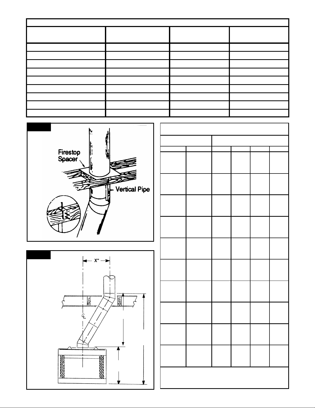
5. See figure 15 for offset calculation: Locate the center
point of the flue on the ceiling with a plumb bob as shown
on page 5. The center of the correct location for the
ceiling opening will be the amount of the offset dimension
away from the ceiling nail. See figure 15. The "X" dimension in the drawing is the amount of the offset. Be sure to
consider the direction that your offset will incline. To
achieve the minimum offset, (see table), attach the return
elbow to the first elbow. To achieve further offset, you
may install various lengths of pipe between the elbows to
a maximum length of 72 inches without a flue support.
6. When the flue penetrates the ceiling at a 30° angle,
install firestop spacer 8230F. (See step 7 on page 8 for
construction detail .)
.
CHIMNEY TERMINATION
HEIGHT 10 FOOT RULE OF
THUMB
Under most conditions the fireplace system will draw
properly if the chimney height is determined in
accordance with the following guidelines:
1. If your chimney penetrates the roof within 10' of its
peak, it must extend at least 24" above your roof's
peak and be at least 36" above the highest point of
the roof opening (see figure 12).
2. If the chimney penetrates the roof farther than 10'
from its peak, measure from the center line of the
chimney to a point 10' away, between the chimney
and the peak of the roof. The top of the chimney
must be at least 24" above this point and at least 36"
above the highest point of the roof opening. (See
figure 13).
3. When figuring required chimney height, the termination counts as 6" of effective chimney height. The
balance of the required height will consist of chimney
sections and the effective height of the firebox.
4. The 10' Rule of Thumb is a guide for calculating
chimney height that works under most conditions.
However, many factors can cause the need for
additional chimney height beyond what the 10' Rule
of Thumb would indicate. Topographical factors can
cause high pressure zones which prevent a chimney
from drawing. This can occur if the house is located
in a low lying area, in a valley or near the base of a
cliff or hillside. The same situation can occur it the
chimney is near other steep roof lines or tall buildings. Areas with high winds also frequently require
higher than normal chimneys. Certain styles of
architecture tend to interfere with a fireplace's proper
draw. If the room in which the fireplace is located
has a very high ceiling, smoke may enter the room
unless the chimney is terminated at a level higher
9
LINEAL, VERTICAL & HORIZONTAL GAIN OF INSTALLED COMPONENTS
ADD
36-3/4"
FOR
36"
FIREPLACES
ADD
6"
FOR
8203D
CAP
ADD 3-3/4"
FOR
8204S
FLUE SUPPORT (IF NEEDED)
VERTICAL ELEVATION CHART
Chimney Only
Chimney Lengths
Number Of
Height Of
OFFSET “X” OFFSET “Y”
COMPONENT ONLY ACTUAL VERTICAL GAIN (CHIMNEY AT 30 DEG,) (CHIMNEY AT 30 DEG.)
36” FIREPLACE 36-3/4” — —
42” FIREPLACE 41” — —
8203D ROUND CAP 6” — —
8232E ELBOW (30 DEGREE) — 3-7/8” 14-5/8”
8212D (12” PIPE SECTION) 10” 5” 8-5/8”
8218D (18” PIPE SECTION) 16” 8” 13-7/8”
8236E (36” PIPE SECTION) 34” 17” 29-3/8”
8248E (48” PIPE SECTION) 46” 23” 39-7/8”
8204S FLUE SUPPORT 3-3/4” 1-7/8” 3-1/4”
Figure 14
Figure 15
* 36” models: 36-3/4”
42” models: 41”
*
“Y”
TOTAL
RISE
*
Inches Feet/Inches 12" 18" 36" 48"
10 0'-10" 1 0 0 0
16 1'-4" 0 1 0 0
20 1'-8" 2 0 0 0
26 2'-2" 1 1 0 0
34 2'-10" 0 0 1 0
46 3'-10" 0 0 0 1
50 4'-2" 0 1 1 0
56 4'-8" 1 0 0 1
62 5'-2" 0 1 0 1
66 5'-6" 2 0 0 1
72 6'-0" 1 1 0 1
80 6'-8" 0 0 1 1
92 7"-8" 0 0 0 2
96 8'-0" 0 1 1 1
102 8'-6" 1 0 0 2
108 9'-0" 0 1 0 2
112 9'-4" 2 0 0 2
118 9'-10" 1 1 0 2
126 10'-6" 0 0 1 2
136 11'-4" 1 0 1 2
138 11'-6" 0 0 0 3
142 11'-10" 0 1 1 2
148 12'-4" 1 0 0 3
154 12'-10" 0 1 0 3
158 13'-2" 2 0 0 3
164 13'-8" 1 1 0 3
172 14'-4" 0 0 1 3
182 15'-2" 1 0 1 3
184 15'-4" 0 0 0 4
188 15'-8" 0 1 1 3
194 16'-2" 1 0 0 4
200 16'-8" 0 1 0 4
204 17'-0" 2 0 0 4
210 17'-6" 1 1 0 4
218 18'-2" 0 0 1 4
228 19'-0" 1 0 1 4
230 19'-2" 0 0 0 5
234 19'-6" 0 1 1 4
240 20'-0" 1 0 0 5
246 20'-6" 0 1 0 5
*
* ADD 41" FOR 42" FIREPLACES
*
*
10

OFFSET AND RISE CHART
INCLUDING ONE SET OF ELBOWS AND FLUE SUPPORTS AS NEEDED
(NOT INCLUDING FIREPLACE OR TERMINATION CAP)
Height Of
Chimney Only (inches)
" X" OFFSET "Y" RISE SET 12" 18" 36" 48" SUPPORT
8-7/8" 23-1/4" 1 1 0 0 0 11-7/8" 28-1/2" 1 0 1 0 0 13-7/8" 31-7/8" 1 2 0 0 0 16-7/8" 37-1/8" 1 1 1 0 0 20-7/8" 44" 1 0 0 1 0 26-7/8" 54-1/2" 1 0 0 0 1 28-7/8" 57-7/8" 1 0 1 1 0 31-7/8" 63-1/8" 1 1 0 0 1 34-7/8" 68-3/8" 1 0 1 0 1 36-7/8" 71-3/4" 1 2 0 0 1 39-7/8" 80-1/4" 1 1 1 0 1 1
43-7/8" 87-1/8" 1 0 0 1 1 1
49-7/8" 97-5/8" 1 0 0 0 2 1
51-7/8" 101" 1 0 1 1 1 1
54-7/8" 106-1/4" 1 1 0 0 2 1
57-7/8" 111-1/2" 1 0 1 0 2 1
59-7/8" 114-7/8" 1 2 0 0 2 1
62-7/8" 120-1/8" 1 1 1 0 2 1
66-7/8" 127" 1 0 0 1 2 1
71-7/8" 135-5/8" 1 1 0 1 2 1
72-7/8" 137-1/2" 1 0 0 0 3 1
74-7/8" 140-7/8" 1 0 1 1 2 1
77-7/8" 149-3/8" 1 1 0 0 3 2
80-7/8" 154-5/8" 1 0 1 0 3 2
82-7/8" 158" 1 2 0 0 3 2
85-7/8" 163-1/4" 1 1 1 0 3 2
89-7/8" 170-1/8" 1 0 0 1 3 2
94-7/8" 178-3/4" 1 1 0 1 3 2
95-7/8" 180-5/8" 1 0 0 0 4 2
97-7/8" 184" 1 0 1 1 3 2
100-7/8" 189-1/4" 1 1 0 0 4 2
103-7/8" 194-1/2" 1 0 1 0 4 2
105-7/8" 197-7/8" 1 2 0 0 4 2
108-7/8" 203-1/8" 1 1 1 0 4 2
112-7/8" 213-1/4" 1 0 0 1 4 3
117-7/8" 221-7/8" 1 1 0 1 4 3
118-7/8" 223-3/4" 1 0 0 0 5 3
120-7/8" 227-1/8" 1 0 1 1 4 3
125-7/8" 232-3/8" 1 1 0 0 5 3
126-7/8" 237-5/8" 1 0 1 0 5 3
TO "Y" DIMENSION ADD 36-3/4" FOR 36" FIREPLACES
TO "Y" DIMENSION ADD 41" FOR 42" FIREPLACES
TO "Y" DIMENSION ADD 6" FOR 8203D TERMINATION CAP
8232E 8204S
ELBOW FLUE
Number Of
Chimney Lengths
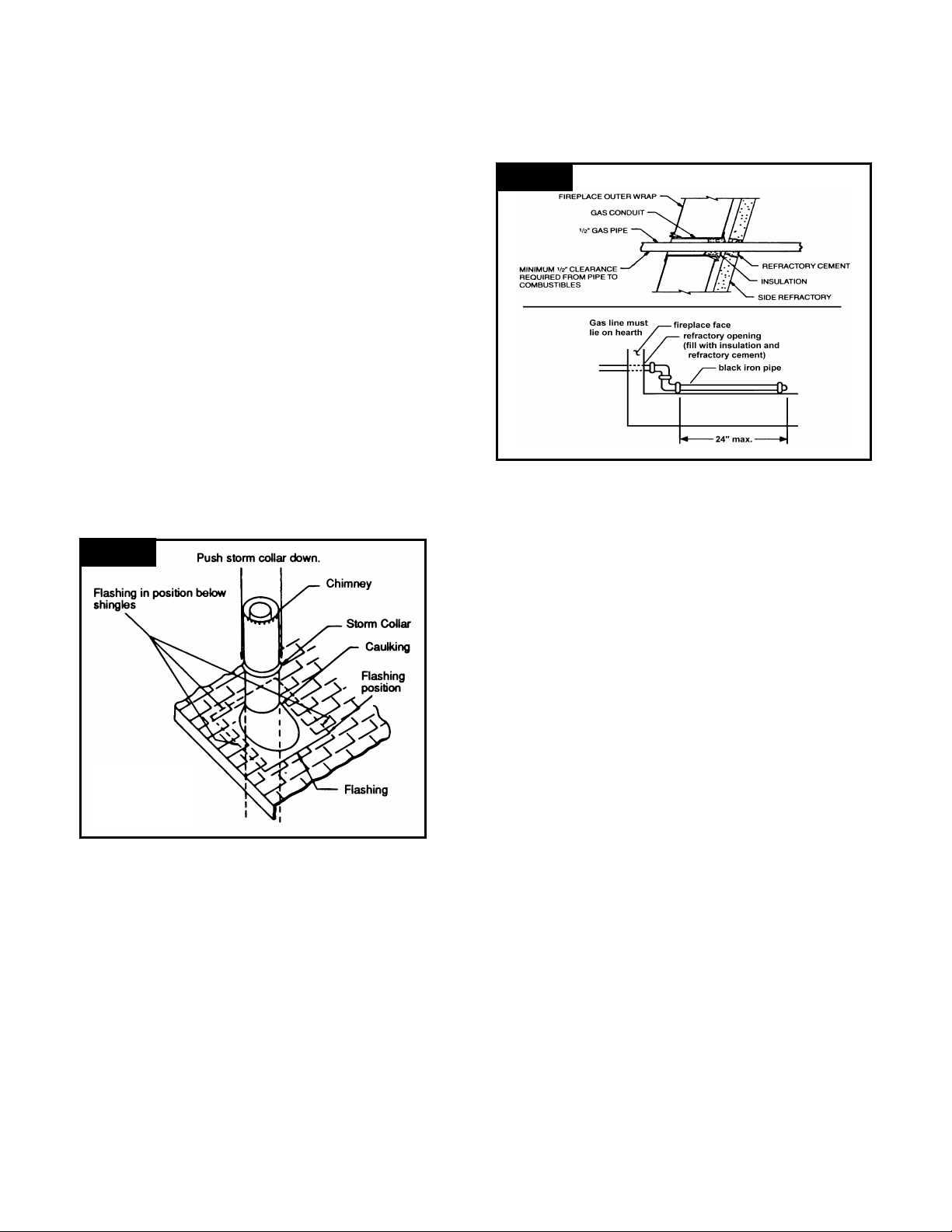
STEP 11. INSTALLING FLASHING
Place the flashing over the chimney pipe where it
penetrates the roof and mark the outline of the flashing on
the roof. Remove the nails from the shingles inside this
outline and to the bottom edge of the roof cutout. Coat the
roof area under the shingles with roofing cement. Slide the
flashing under the shingles on the sides of the flashing and
re-nail the top and side shingles. DO NOT nail through the
lower portion of the flashing. If necessary, cover the side
and top of the flashing with the salvaged shingles. The
flashing should cover the lower side of the roof opening as
pictured in figure 16.
STEP 12. INSTALLING THE STORM COLLAR
The storm collar is assembled to the chimney system next.
Holding the adjustable storm collar with the tab of the collar
in your right hand, put the collar around the flue pipe. Push
the tab on the collar through the slot provided. Pull the tab
through and bend it just enough so that the collar may be
raised upward.
Apply waterproof caulking around the flashing where the
collar fits around the top of the flashing. Push the storm
collar down s ecurely on the sealer and flashing. To secure
the collar, pull the tab through the slot as far as possible
and bend the tab over to hold it in place.
STEP 13. INSTALLING THE TERMINATION CAP
A chimney termination is required to finish the installation.
The following instructions are for the 82O3D termination.
Refer to the instructions packed with the termination for
additional information.
Figure 16
Installing
flashing and
storm collar
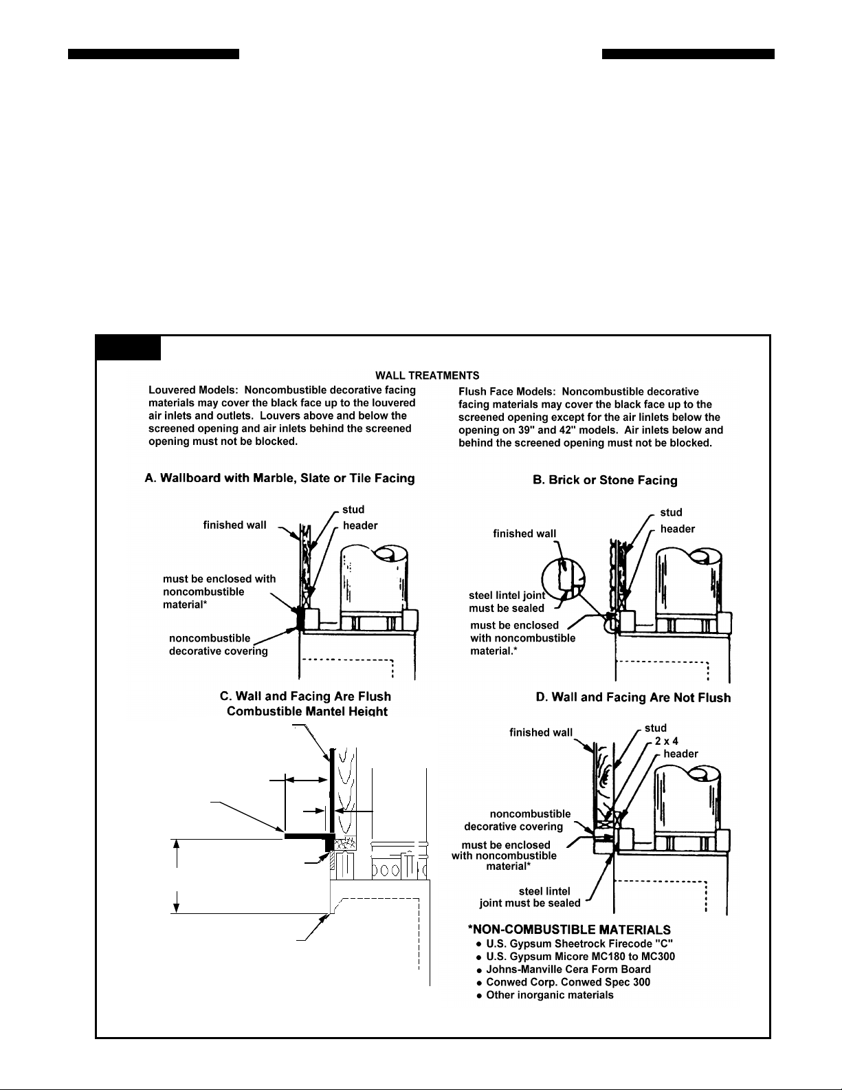
INSTALLING A GAS LINE
All Temco fireplaces are designed to accept a 1/2" gas line.
The gas appliance must be certified, listed or approved for
installation in a solid fuel fired fireplace by a nationally
recognized certification agency. A gas appliance must be
installed and operated in accordance with the instructions
provided by the appliance manufacturer and the National
Fuel Gas Code ANSI Z223.1. The fireplace has a factory
installed tube for insertion of the gas line. Refer to page 4
for gas line inlet location.
NOTE: A minimum 1/2" clearance from the gas pipe must
be maintained within 4" of the fireplace, (see figure 17).
To install the gas line, use a hammer and punch gently to
knock a hole through the refractory at the emboss. Remove
the insulation from the inlet tube. Run the line to just outside
the gas inlet hole of the fireplace. Slide a 1/2" gas line
nipple through the tube and attach to the line. Finish
installation by either capping gas line inside fireplace or by
attaching an approved gas appliance in accordance with its
installation instruc tions. Re-install insulation around the gas
line to seal between the gas line and gas conduit. Seal
around the gas line and the refractory with refractory
cement.
CAUTION: When using a decorative appliance, the
fireplace damper must be set in the fully open position.
Figure 17
OPTIONAL COLD CLIMATE INSTALLATIONS
NOTE: THE FOLLOWING INFORMATION ON SEALING
AND INSULATING THE FIREPLACE IS LEFT UP TO THE
DISCRETION OF THE INDIVIDUAL HOME
MANUFACTURER THESE STEPS ARE NOT REQUIRED
FOR SAFE INSTALLATION OF THE FIREPLACE
SYSTEM.
The insulation and sealing of the enclosure around the
fireplace is very important in cold climates. If the enclosure
is insulated and sealed properly, you can avoid future cold
air problems. The time taken to install the firebox correctly
is well worthwhile.
INSULATION OF THE FIREPLACE ENCLOSURE
When in a chase or on an outside wall, the fireplace
enclosure can be insulated like any other outside wall.
Insulation can be installed on the outside walls and the wall
above the fireplace. In chase installations, install a firestop
at the first ceiling level above the fireplace and seal the
remaining area with either sheet metal or 1/2" gypsum
wallboard. Insulation may then be installed above the
sheeting material. Required clearances to the chimney pipe
must be maintained. Lining the interior walls of the fireplace
enclosure with gypsum wallboard will further reduce cold air
infiltration.
INSULATE TO SEAL UNDER THE FIREPLACE
Insulating under the fireplace is beneficial. The fireplace
should be placed on insulating board. It is important that a
hard, rigid surface be maintained, so do not use fiberglass
insulation for this purpose. In a chase that cantilevers
outside the house, it is beneficial to insulate between the
floor joists.
CAUTION: When installing a fireplace in an insulated
enclosure, be sure to maintain all marked air spaces.
SEAL SEAMS
Seal between the fireplace and finishing materials. Use high
temperature caulk. See figure 11 for the details of sealing
spaces between the fireplace and finishing materials. Note
the small amount of insulation installed across the top of the
fireplace and down the sides as a backing for the caulk.
DO NOT BLOCK INLET HOLES AT BASE OF CHIMNEY
12
FINISHING YOUR FIREPLACE
There are a wide variety of finishing materials available for
your TEMCO fireplace from formal wall treatments with
marble and mantels to rustic wood paneling, stone or brick.
It is important that the black face surface of the fireplace not
be covered with any type of combustible material (Note:
This does not apply to the face extension panels). Noncombustible facing materials such as marble, brick or
ceramic tile may overlap the black face of the fireplace but
must not cover louvered vents above and below the
opening. Seal all joints between the black fireplace face
and the wall covering with a heat -resistant material (4000 F.
Min.) such as rock wool insulation or mortar. Be sure to use
high temperature adhesive or mortar when anchoring brick,
stone or tile to the face of the fireplace. Check to see
whether man-made brick and stone are made of noncombustible materials before using them on the face of th e
fireplace. Some of these products contain combustible
Figure 18
materials. Combustible wall coverings such as paneling or
wallboard may not overlap the black face of the fi replace.
The space between the wall covering and the fireplace
should be sealed with a heat -resistant material such as rock
wool insulation or mortar (4000 F. Min.).
NOTE: An "L" shaped steel lintel must be installed across
the top of the firebox opening where facing materials such
as solid brick or stone are used on the face of the firebox. It
acts as a support/firestop. It should be attached to the face
of the fireplace with screws and sealed to the fireplace with
a heat -resistant sealer.
Prefabricated self supporting surround kits may be used
with the fireplace. Sealing above the fireplace opening
must be done using mortar, insulation, or other sealant
rates at 4000 F. or higher.
FINISHED WALL
10”
COMBUSTIBLE
MANTLE
MAX
12”
MIN
*Noncombustible material must enclose space
between top of standoff and top of fireplace front.
Examples of noncombustible materials are:
SEAL WITH NON -
COMBUSTIBLE
MATERIAL
TOP OPENING
OF FIREPLACE
*
1 1/2”
MAX
13

Figure 19
MANTEL LEG PROJECTION
Mantel legs may project along the radiation line as illustrated.
REFERENCE DIMENSIONS
A B
1-1/4” min. 1-11/16”
6” min. 2-5/8”
7" min. 3"
8" min. 3-1/2"
10" min. 4-3/8"
12" min. 5-1/4"
nailing flange
combustibles
radiation line
fireplace face opening
allowed
combustible material
(mantle/surround legs)
Figure 20
Hearth Installation
(See Note Below)
(See Note Below)
(See Note Below)
NOTE: When installing the hearth extension, a protective
metal safety strip is not required below the front face of the
fireplace and mating edge of the hearth extension if the
following steps are taken:
1) The pre-fabricated hearth extension (or site built) must
be secured to the floor of the home to prevent shifting.
Various methods of attachment may be used including
screws, nails, or common construction adhesives.
*36” models: 16”
42” models: 20”
(See Note Below)
2) After the fireplace and hearth extension have been
secured, the gap between the fireplace and hearth
extension must be filled or sealed with a noncombustible grout, caulk, or sealant.
(OR)
If a protective metal strip is used under the space between
the fireplace and hearth extension, sealing of the gap
between the fireplace and hearth extension is optional.
14

USING YOUR FIREPLACE
1. Open the firescreen by grasping the handles and pushing
them back to each side.
2. The flue damper rod is located behind the mesh screens.
To open the damper, slide the rod to the right. To close,
slide the rod to the lef t.
3. If the combustion air kit has been installed, the inlet air
damper should be in a fully open position before you start
a fire. Reach behind the screen and release the control
rod on the front of the left side of the firebox. To open,
turn the control until it is pointing down. To close the
damper, rotate the control rod counterclockwise until it is
pointing to the three o'clock position. The control rod will
lock in the closed position and swing free in the open position.
4. A TEMCO fireplace grate must be used in this fireplace. It is
pre-installed at the factory as an integral part of the fireplace.
5. Light a piece of crumpled paper and hold it high inside
the fireplace. This will warm the flue and start the
chimney "drawing".
6. Light the paper in the grate and add kindling. As the
kindling catches, add more or heavier wood until the fire
is well established. Be careful not to "smother" the fire.
7. WARNING: NEVER USE GASOLINE, GASOLINE-TYPE
LANTERN FUEL, KEROSENE, CHARCOAL LIGHTER
FLUID OR SIMILAR LIQUIDS TO START OR FRESHEN UP
A FIRE IN THIS FIREPLACE. KEEP ALL SUCH LIQUIDS
WELL AWAY FROM THE FIREPLACE WHILE IT IS IN USE .
8. Close the right firescreen first and then the left firescreen,
being sure that they overlap. Keep the firescreens
closed at all times except when adding fuel.
9. Ashes that build up from burning logs must be removed
periodically to allow space for air to move under and up
through the fuel for combustion. If these ashes are
allowed to accumulate until the air flow is blocked, the
grate may become badly warped from excessive heat.
10.A fireplace needs a steady supply of air in order to draw
properly. Many houses or apartments which are well
sealed lack sufficient air for normal operation. Ventilating
fans, exhaust hoods or central heating systems often
cause fireplaces to smoke by stealing the fireplace's
combustion air. If the volume is enough, it can reverse
the flow of air in the fireplace and cause smoking.
11.Use solid wood for fuel. Use dry and well seasoned
wood. Do not burn scrap construction lumber; it
produces excessive sparks. Never use woods dipped in
tar, pitch, creosote, etc. as this produces sputtering,
smoking fires with toxic fumes. Do not use wood
products with synthetic binders like plywood or artificial
logs as these produce abnormally high temperatures
and may cause deterioration of chimney material.
12.DO NOT OVER-FIRE WITH EXCESSIVE FUEL LOADS
SUCH AS LUMBER, WRAPPING PAPER, CHRISTMAS
TREES, ETC. THE FIREPLACE IS OVER-FIRED IF THE
TOP OF THE FLAMES ARE GOING UP INTO THE
CHIMNEY OR LICKING OUT OF THE FIREBOX.
? OVER-FIRING WITH THE GLASS DOORS IN THE
CLOSED POSITION CAN CAUSE THE GLASS TO
SHATTER RESULTING IN PROPERTY DAMAGE AND/OR
PERSONAL INJURY. TEMCO DOES NOT WARRANT
THE GLASS AND IS NOT RESPONSIBLE FOR
CONSEQUENTIAL PROPERTY DAMAGE AS STATED IN
THE SEPARATE GLASS DOOR WARRANTY.
13.Creosote Formation and Need for Removal: When
wood is burned slowly, it produces tar and other organic
vapors which combine with expelled moisture to form
creosote. The creosote vapors condense in the relatively
cool chimney flue of a slow-burning fire. As a result,
creosote residue accumulates on the flue lining. If
ignited, this creosote makes an extremely hot fire. The
chimney should be inspected at least twice a year during
the heating season to determine if a creosote buildup has
occurred. If creosote has accumulated, it should be
removed to reduce the risk of a chimney fire.
14.CHARCOAL AND COAL MAY NOT BE BURNED IN
THIS FIREPLACE.
15.NEVER CLOSE ANY DAMPERS UNTIL YOU ARE
CERTAIN THAT THERE ARE NO WARM EMBERS.
16.When the fire has gone completely out, close all
dampers. This will prevent excessive heat loss up the
chimney and excessive water on the hearth. If a
combustion air kit is installed, close the inlet air damper.
17.The brick-like refractory on the floor, back and sides is
reinforced with steel but can be cracked and broken. Don't
drop logs or build fires directly against refractories. A careful
"burn-in" of your fireplace is recommended during initial use.
For the first few fires, build modest fires. This will cure the
refractories properly. Hairline cracks may appear in the
refractories but do no harm to their performance.
18.It is important for the chimney to be high enough to draw
properly. The chimney should extend 3' above the highest
point where it passes through the roof and 2' above any
portion of the roof horizontally within 10'. See pages 9 and
10.
19.Disposal of Ashes: Ashes should be placed in a metal
container with a tight fitting lid. The closed container of
ashes should be placed on a noncombustible floor or on the
ground, well away from all combustible materials, pending
final dispo sal. If the ashes are disposed of by burial in soil or
otherwise locally dispersed, they should be retained in the
closed container until all cinders have thoroughly cooled.
20.WARNING: Any accessory component(s) used with
this fireplace other than those specified, must be
listed or approved by a nationally recognized
certification agency for the application and be
installed and used in accordance with the accessory
manufacturer’s instructions and local codes.
21.Access to chimney for cleaning: To remove the
termination cap, remove the three #10A x 7 hex-head
screws from the termination brackets. Grasp the skirt
with one hand on each side and pull up. To replace the
cap, reposition the termination cap on the chimney pipe
and align the terminati on brackets with the holes in the
pipe. Securely attach the termination cap to the chimney
with the three screws removed earlier.
22.WARNING: FIREPLACES EQUIPPED WITH DOORS
SHOULD BE OPERATED ONLY WITH DOORS FULLY
OPEN OR DOORS FULLY CLOSED. IF DOORS ARE
LEFT PARTLY OPEN, GAS AND FLAME MAY BE
DRAWN OUT OF THE FIREPLACE OPENING,
CREATING RISKS OF BOTH FIRE AND SMOKE.
23.Keep all combustibles such as furniture, draperies,
papers and stored wood away from the front of the
fireplace.
15

REPLACEMENT PARTS
The following replacement parts are available from your TEMCO dealer.
Description
1. Firescreen rod, strai ght 2 65864 65648
2. Screws for screen rods 2 68188 68188
3. Firescreen with rings 2 62197 66146
4. Screen retainer 4 62222 62222
5. Refractory retainer, right side 1 70358 68316
6. Refractory retainer, left side 1 70358 68339
7. Refractory retainer, front 1 - 68372
8. Screws for refractory retainers 2 68188 68188
9. Right side refractory 1 70355 68337
10.Left side refractory 1 70355 68338
11.Back refractory 1 70357 66993
Quantity
Part #
42" 36"
12.Bottom refractory 1 70354 68336
13.Integral grate 1 70361 68373
14.Grate retaining bracket 2 66130 66130
REPLACEMENT PARTS - GLASS DOORS
The following replacement parts are available from your TEMCO dealer.
Description Quantity Part #
1. Handles 2 67987
2. Door Guide 1 68344
3. Spring Push 1 69891
4. Spring Clip 2 62216
5. Screw #10A x 1/2” 6 49007
6. Screw #12A x 1/2” 6 66365
16

LIMITED WARRANTY AND EXCLUSIONS
For TEMCO Low Profile, Front -Opening, Wood Burning Fireplaces
Models TLC42-4MB, TLC36-3MB, TFC36-3M
This Limited Warranty covers the above described fireplace and chimney systems. Accessories such as glass
doors, combustion air kits and fans are covered in separate warranties.
The First Year of Coverage
During the first year after installation, TEMCO Fireplace Products, Inc. will at its option repair or replace any
defective part of the fireplace or chimney system or refund to the original owner a sum of money not to exceed the
suggested retail price of the system at the time of purchase. The date of installation must be verified by
acceptable proof of purchase, canceled check or recorded and dated deed to the property where the system is
installed.
The Second Through Fifth Years of Coverage
From the second through the fifth year after installation, TEMCO will make available to the original owner, at no
charge, at its factory a replacement for any defective part in the fireplace or chimney system except for refractories
or grates. Defective refractories and grates can be replaced by the original owner at TEMCO’s factory at fifty
percent (50%) of the current list price from the second through the fifth years after installation.
The Sixth Through the Tenth Years of Coverage
From the sixth through the tenth years after installation. TEMCO Fireplace Products will make available to the
original owner at fifty percent (50%) of the current suggested list price at its factory a replacement for any defective
part in the fireplace or chimney system except for refractories and grates which may be replaced at full list price.
Some states do not allow limitations on how long an implied warranty lasts so the above limitations may not apply
to all consumers.
What is Not Covered
This warranty does not cover any cost or expenses not herein set forth as being the responsibility of TEMCO
Fireplace Products and specifically does not cover the following:
• Anyone other than the original owner.
• Shipping costs after the first year of coverage.
• Labor after the first year of coverage.
• Damage caused by improper installation, misuse, abuse or alteration of the fireplace or chimney system.
• Cracks in refractories that do not affect safe operation.
• Any work done or cost incurred without written cons ent from TEMCO Fireplace Products.
• Installation performed by unlicensed or unqualified agent per NFPA 211.
Limitations and Exclusions
1. TEMCO Fireplace Products authorizes no one to add to or alter this Limited Warranty.
2. TEMCO Fireplace Products is not liable for incidental, consequential, special or contingent damages. Some
states do not allow exclusion or limitation of incidental or consequential damages, so the above limitation or
exclusion may not apply to all consumers.
3. This Limited Warranty ap plies only to the original owner of the fireplace and chimney system with the model
number described above or the original owner of the dwelling in which one of the above described fireplace
and chimney systems is installed.
4. Removal of fireplace from original installation site voids warranty.
5. TEMCO Fireplace Products reserves the right to investigate any or all claims against this warranty.
Owner’s Duties
The fireplace and chimney to which this Limited Warranty applies must be installed and used in strict compliance
with TEMCO Fireplace Products installation manual. Failure to do so will void this warranty. If you have a
problem with your fireplace, first consult the installation manual to insure that your system has been properly
installed and is being used in accordance with the manual. After doing so, if you still have a problem, contact the
nearest TEMCO dealer or distributor. If necessary, you may find out the name of your nearest dealer or distributor
by writing TEMCO Fireplace Products and requesting such information. Upon notification of your problem, a
representative of the dealer or distributor will inspect your fireplace. A determination will be made whether or not
your problem is covered under this Limited Warranty, and you will be cont acted.
This Limited Warranty is given in lieu of any other expressed or implied warranties.
17

Customer Copy
To register your warranty, please provide the information indicated on this form and mail it to:
TEMCO Fireplace Products
301 Perimeter Park Dr.
Suite 227
Nashville, TN 37211
Model #_______________________________________ Serial #_________________________________________
WARRANTY REGISTRATION
Purchaser
Address
Phone
Retailer
Address
Phone
Date of Purchase
Please Answer the Following Questions (Check Box):
1. Type of Home Single Family Duplex Apt. Mobile Home
Cabin/Vacation
2. Installed in (Room) Living Family Great Rec Bedroom
Other
3. Other Choices Considered Vented Decorative Gas Logs/Fireplace
Direct Vent Fireplace Gas Insert Woodburning Insert
Vent-Free Gas Fireplace
4. Why Did You Choose Woodburning? (Rank in Order of Importance: 1-6)
___Appearance ___Location Flexibility ___Builder Decided
CUT ALONG LINE
To register your warranty, please provide the information indicated on this form and mail it to:
TEMCO Fireplace Products
301 Perimeter Park Dr.
Suite 227
Nashville, TN 37211
WARRANTY REGISTRATION
Purchaser
Address
Phone
Retailer
Address
Phone
Date of Purchase
Please Answer the Following Questions (Check Box):
1. Type of Home Single Family Duplex Apt. Mobile Home
Cabin/Vacation
2. Installed in (Room) Living Family Great Rec Bedroom
Other
3. Other Choices Considered Vented Decorative Gas Logs/Fireplace
Direct Vent Fireplace Gas Insert Woodburning Insert
Vent-Free Gas Fireplace
4. Why Did You Choose Woodburning? (Rank in Order of Importance: 1-6)
___Appearance ___Location Flexibility ___Builder Decided
18

Limited Warranty and Exclusions
Temco Fireplace Products, Inc. warrants to the original purchaser that this glass door package is free from defects in
material and workmanship for a period of one (1) year from the date of original purchase. If any part of this glass
door fails during this period, Temco Fireplace Products, Inc. will - at its option - either repair or replace the part
subject to the following terms:
TERMS AND CONDITIONS OF ONE-YEAR LIMITED WARRANTY
If the original purchaser of a Temco glass door kit believes that the part has failed during such period of one (1) year
due to a defect in material and workmanship, he should promptly return the defective part to the nearest Temco
dealer or distributor. Temco acceptance of any goods so shipped shall not be construed as or deemed an admission
of any defect. Transportation costs will be paid by the consumer both to and from the factory and the dealer or
distributor. Shipment from the dealer or distributor must be FOB Temco factory. If, in the sole judgment of Temco
Fireplace Products, Inc., upon inspection it appears that the part has failed due to a defect in material and
workmanship, Temco will - at its option - either repair or replace the part at no cost for the part. All labor charges
incurred in the removal and replacement of the defective part will be incurred by the original purchaser. The remedy
contained herein shall be the sole remedy for the breach of any express or implied warranty of Temco.
LIMITATION OF DURATION AND DISCLAIMER OF IMPLIED WARRANTIES
Any implied warranties of Temco Fireplace Products, Inc., including warranties of merchantability or fitness for a
particular purpose, which arise out of the sale of Temco Glass Door Kits are limited to the duration of the warranties
expressed above. In no event shall any implied warranty applicable to the glass door kits be effective after the
expiration date of the above limited warranty.
(A) Glass Breakage. Temco Fireplace Products does not warrant against breakage of glass. Breakage is normally
due to handling and shipping which is covered by the freight handler. Breakage during use can be attributed to
over-firing the fireplace which means flames are going up the chimney or licking against glass when the doors
are in the closed position. The extreme heat can cause the doors to shatter, resulting in possible property
damage.
(B) Disclaimer of special, incidental or consequential damages. Temco Fireplace Products, Inc. shall have no
liability for any special, incidental or consequential damages arising from the sale or use of the glass door kit.
Temco makes no warranty or representation and assumes no responsibility for the performance of any product
in which the glass door is contained.
(C) Further disclaimer. Any express or implied warranties of Temco, including the limited warranties of
merchantability or fitness for a particular purpose, shall not apply and Temco assumes no responsibility for any
damages that result due to the following:
(1) If said glass door kit is not installed and operated at all times in accordance with the installation and
operation instructions furnished.
(2) In any case where the said glass door kit has been either tempered with or altered in any way.
(3) In any case, where in the sole judgment of Temco Fireplace Products, the glass door kit has been misused,
used negligently or suffered damage.
(D) The warranties herein are expressly in lieu of any other expressed or implied warranty. Temco has not
authorized any person to make any representations or assume any liability in connection with the sale of Temco
glass door kits except such representations that are contained herein and in the specific installation and
operation instructions furnished with the glass door kit model.
(E) Temco makes no express warranty and disclaims all implied warranties as to accessories or parts not supplied
by Temco.
19

ONE YEAR LIMITED WARRANTY AND EXCLUSIONS
TEMCO Fireplace Products, Inc., (hereafter, TEMCO) whose addresses are shown below, warrants to the original
purchaser that its blower is free from defects in material or workmanship for a period of one (1) year from the date of
original purchase. This warranty is a limited warranty only and subject to all of the terms and conditions set forth below.
TERMS AND CONDITIONS OF ONE YEAR LIMITED WARRANTY
If the original purchaser of a TEMCO Blower Kit believes that a part of the blower has failed during the period of one (1)
year from the date of purchase due to a defect in material or workmanship, he should promptly return the part to the
nearest TEMCO dealer or distributor with proof of purchase date. If the original purchaser is unsure where the nearest
dealer or distributor is located, then the purchaser should write TEMCO Fireplace Products, Inc., Warranty Division, at one
of the addresses listed below to obtain such information. If the TEMCO dealer or distributor is not able to resolve any
claim under this warranty, then the purchaser shall direct the dealer or distributo r to ship said part to TEMCO Fireplace
Products, Inc., Warranty Division, at one of the addresses below. All transportation costs must be paid by the purchaser
both to and from the dealer, distributor or TEMCO and shipment from the dealer or distributor must be F.O.B. TEMCO.
Proof of purchase date must accompany any such part delivered or shipped to the dealer or distributor or TEMCO.
Acceptance of any part shipped or delivered to any dealer, distributor or TEMCO shall not be construed as or deemed as
an admission of any defect.
Within a reasonable time from date of receipt of any part believed to be defective and proof of date or purchase, TEMCO
shall inspect said part, and, if it should appear - in TEMCO's sole judgment - that the part has failed during the period of
one (1) year from date or original purchase due to a defect in material or workmanship, TEMCO will - at its option - either
repair or replace the part at no cost to purchaser; however, any labor or other charges incurred in the removal or
replacement of the part, as well as any delivery or shipping charge, will be the sole responsibility of purchaser.
This warranty is not transferable in any manner by the original purchaser and is effective only if the part of TEMCO's
blower is accompanied by proof of purchase within one (1) year of the date that a claim is made under this warranty.
LIMITATIONS
(A)This warranty expires upon transfer of the blower or any part from the original purchaser to any other person or upon
the expiration of one year from the date of original purchase, whichever occurs first.
(B)TEMCO makes no warranty and assumes no responsibility whatsoever as to parts or accessories not manufactured by
TEMCO, but you may have rights against the manufacturers of such parts and accessori es under their warranties or the
law of your jurisdiction. TEMCO specifically makes no other warranties than contained herein and makes no warranties,
representations and accepts no responsibility for the performance of any product which the blower assembly might be
used with or attached to other than the fireplace model for which the blower is designed.
(C)THIS WARRANTY IS EXPRESSLY IN LIEU OF ALL OTHER WARRANTIES, EXPRESSED OR IMPLIED, INCLUDING
THE WARRANTY OF MERCHANTABILITY AND FITNESS FOR A PARTICULAR PURPOSE. NO PERSON IS
AUTHORIZED BY US TO MAKE ADDITIONAL OR DIFFERENT WARRANTIES AND THE PURCHASER
ACKNOWLEDGES THAT NO OTHER REPRESENTATIONS WERE MADE TO HIM OR RELIED UPON BY HIM WITH
RESPECT TO THE WARRANTY APPLICABLE TO THE PRODUCT. SOME STATES DO NOT ALLOW THE
EXCLUSION OF IMPLIED WARRANTY SO THE ABOVE EXCLUSION MAY NOT APPLY TO YOU.
(D)TEMCO accepts no responsibility for damages or expenses resulting from failure to observe installation and operating
instructions; in any case where the blower has been tampered with or altered in any fashion, or where, in the sole
judgment of TEMCO, the blower has been damaged, misused or used in a negligent manner.
? This warranty gives you specific legal rights and you may also have other rights which vary from state to state.
20
 Loading...