

Temco TLC39-22, TLC39-22I, TFC39-22 Installation Instructions Manual
TEMCO FIREPLACE PRODUCTS, Inc.
Click here to print
Installation Instructions for 39" Fireplaces
Models TLC39-22,TLC39-22I,TFC39-22
READ AND SAVE THESE INSTRUCTIONS
Louvered 39" Heat Circulating Fireplace
TLC39-22
39" louvered heat -circulating fireplace.
• Optional Combustion Air Kits AIR -5, AIR-5A, AIR-5B,
AIR-7, AIR -3B.
• Optional Glass Doors CLS-4, CLS-3, CX31, CX41.
• Optional Blower Kit BL3922. Requires junction box JB-
2.
TLC39-22I (With insulated outer wrap)
39" louvered heat-circulating fireplace with fully insulated
outer wrap.
• Optional Combustion Air Kits AIR -5, AIR-5A, AIR-5B,
AIR-7, AIR -3B.
• Optional Glass Doors CLS-4, CLS-3, CX31, CX41.
• Optional Blower Kit BL-1. Requires junction box JB-2.
Mobile Home Installation: Models TLC39-22 and
TLC39-22I are listed for use in mobile homes with a
TEMCO double-wall 8" diameter air-cooled chimney and
components, listed on p.3, when installed with firestop
This book contains your installation instructions and should
be kept in a safe place. It will be a handy reference guide
to operating your fireplace after installation. For you to
realize all the advantages and use of your fireplace, you
must carefully follow all the instructions contained in the
book regarding installation and operat ion of the appliance.
These instructions should be read carefully in their entirety
before beginning installation.
It is suggested that you wear work gloves and safety
Flush Face 39" Heat Circulating Fireplace
thimble UFT8-1, combustion air kit AIR-3B, and glass
doors CLS-4, CLS-3, CX31, CX41.
TFC39-22
39" flush-hearth heat -circulating fireplace.
• Optional Combustion Air Kits AIR-5, AIR-5A, AIR-5B,
AIR-7.
• Optional Glass Doors CLS-3, CX31.
BE SURE TO FOLLOW EXACTLY THE SPECIFIC
INSTALLATION RESTRICTIONS THAT APPLY TO THE
MODEL YOU ARE INSTALLING. Be sure you follow
these rules exactly. The model number of the fireplace is
located on a metal label behind the firescreen in the
upper right corner of the front of the fireplace.
Listed by Underwriters Laboratories, Inc., File #MH10105.
ICBO Evaluation Service, Inc. Report for Underwriters
Laboratories, Inc. - AA668/TL 157.
glasses to protect your hands and eyes when installing your
freestanding fireplace.
NOTE: Authorities having jurisdiction, (i.e. building
inspectors, fire marshals, etc.), should be consulted before
installation in order to determine whether a permit is
required.
All models are listed for use in residential construction in
the United Sta tes with TEMCO double-wall 8" diameter aircooled chimney and components listed on p.3.
Underwriters
Laboratories Inc. R
File MH10105
P.O. BOX 1349 Manchester, TN 37355
P.O. Box 1148 Perris, CA 92572
1773 Parque Industrial Cachanilla
Mexicali, B. C. 21600
REV. 8/14/02 8:05 AM 72350J

CONTENTS
Introduction ........................................................................................................................................ Page 3
Temco Chimney System .........................................................................................................................3
A Few Basic Rules .................................................................................................................................3
Planning Ahead ...........................................................................................................................................4
Choosing the location for your fireplace ...................................................................................................4
Outside air kit accessories ......................................................................................................................5
Gas Line ................................................................................................................................................5
Drafts ....................................................................................................................................................5
Locating flue pipe placement ..................................................................................................................5
Chimney outlet .......................................................................................................................................5
Firebox and chimney system clearances .................................................................................................5
Determining the R-Values .......................................................................................................................6
Fireplace Installation ....................................................................................................................................7
Installing the firebox ...............................................................................................................................7
Installing the chimney .............................................................................................................................8
Chimney termination height "10 Foot Rule of Thumb" ...............................................................................9
Offset installations ...................................................................................................................... 9, 10, 11
Flashing and storm collar ......................................................................................................................12
Installing the termination .......................................................................................................................12
Chase installations ...............................................................................................................................12
Installing a gas line ...............................................................................................................................13
Cold climate installations ......................................................................................................................13
Mobile home installation .......................................................................................................................14
Finishing Your Fireplace .......................................................................................................................15, 16
Using Your Fireplace ..................................................................................................................................17
Replacement Parts .....................................................................................................................................18
Warranty ...................................................................................................................................................19
Warranty Registration .................................................................................................................................20
2

INTRODUCTION
TEMCO CHIMNEY SYSTEM
8" Diameter Double Wall Chimney Sections
8212D 8" Diameter Chimney - 12" Section
8218D 8" Diameter Chimney - 18" Section
8224D 8" Diameter Chimney - 24" Section
8236D 8" Diameter Chimney - 36" Section
8248D 8" Diameter Chimney - 48" Section
8204S Flue Support
SC1215 - 1 Storm Collar
8232E 30° Elbow Set
8215ER 15° Unitized Elbow
8204F-1 Round Firestop Spacer
8230F-1 30° Firestop Spacer
8206F 0-6/12 Roof Flashing
8212F 7-12/12 Roof Flashing
Terminations
8203D Round Termination Cap
STD-22 Round Chase Cap
ARC-52 Architectural Cap
PRC-12 Pyramid Cap
LPC-12 Long Pyramid Cap
TCS-12 Conical Cap
Chimney Enclosures
CEK12-1 12" Chimney Enclosure
CEK18-1 18" Chimney Enclosure
CEK48-1 48" Chimney Enclosure
CEKELB-1 Elbow Chimney Enclosure
CEKFS-1 Firestop for CEK's
HSS-1 Hearth Safety Strip
BEFORE YOU BEGIN ...
A FEW BASI C RULES
1. The instructions on the following pages were designed to
make the installation of your TEMCO fireplace as quick
as possible. It is important that they be followed. This
fireplace should be installed by a skilled craftsman.
2. Use only TEMCO manufactured components, listed
under TEMCO CHIMNEY SYSTEM (above), when
installing a TEMCO fireplace. Substituting other
manufacturers' components for, or altering TEMCO
parts, will void the UL listing and the TEMCO
warranty.
3. Check local building codes for rest rictions which may not
be contained in this manual.
4. The fireplace design permits installation and framing
adjacent to combustible materials. Do not set the
fireplace on vinyl flooring or carpets.
? COMBUSTIBLE MATERIALS MUST NOT OVERLAP
THE SURFACE OF THE BLACK FRONT FACE
PANELS. COMBUSTIBLES MAY BE INSTALLED
OVER THE SIDE NAIL FLANGES UP TO THE EDGE
OF THE FRONT FACE SURFACE.
5. ALL CHIMNEY SECTIONS, ELBOWS AND FLUE
SUPPORTS REQUIRE AN ABSOLUTE MINIMUM OF
1" AIR SPACE CLEARANCE TO ALL
COMBUSTIBLES.
6. The minimum distance from the fireplace opening to an
adjacent combustible wall is 17½". See Figure 4 for
alternative wall shields an d required R-factors.
7. If the floor in front of the fireplace is combustible, a
protective hearth extension must be used. Raised or floor
level extensions may be constructed. On TFC39 only, a
raised hearth extension may be flush with the fireplace
hearth. It must be a minimum of 16" x 52". For a raised
hearth on louvered models, the fireplace must also be
installed on a platform. A hearth extension installed
directly on the floor must be a minimum of 16" x 52".
? Since many hearth extension materials are not insulating
materials, a layer of non-combustible inorganic insulating
material must be used also. See Figure 4 for R-factor
requirements.
8. Adhere to the 10' Rule of Thumb for chimney height. See
Figures 15 and 16.
9. Chimney supports:
a. Flue support is required for every 35' of vertical system
height.
b. Flue support is required for every 6' of offset chimney.
c. Guy wire stabilizer is required for chimneys extending
more than 6' above roof line.
10.Only TEMCO model glass doors may be installed on
these fireplaces.
11.The barometric damper on the Combustion Air Kit allows
air to be drawn from above, below, or behind the
fireplace; but air must never be drawn from the attic or
garage spaces. Refer to the air kit installation manual for
complete installation and use information.
12.Check your local building code to determine if grounding
is required and what procedure should be followed.
Grounding is recommended by the manufacturer if you
live in an area of high risk due to electrical storms.
13.System height:
a. 12'6" minimum height (site-built construction) - no
elbows.
b. 60' maximum height.
c. Four 30° elbows maximum per system. Minimum total
height:
? Two elbows, 13'6"
? Four elbows, 21'
c. Maximum distance between elbows without support is
6'. Maximum run of inclined chimney is 20'.
14. On louvered models, when installing a blower kit, it is
necessary to bring a power source to the fireplace
before it is enclosed. See Blower Kit installation
instructions.
15. For manufactured home installation requirements, see
page 14.
3
PLANNING AHEAD
CHOOSING THE LOCATION FOR
YOUR FIREPLACE:
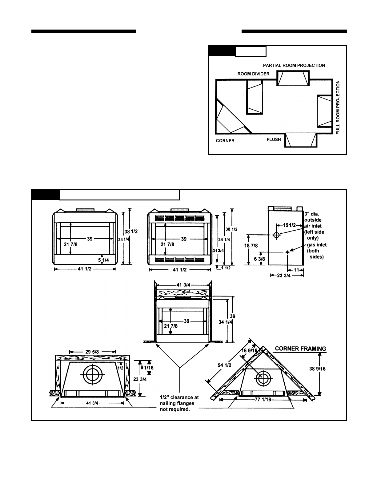
Figure 1 shows some of the many ways your fireplace
may be installed. Consider the traffic pattern in your
room and the location of doors and windows. A corner
location may be best where space is limited.
Your fireplace weighs no more than some of your fine
furniture. If the fireplace is located near a load bearing
wall, additional supports to the foundation will not be
necessary. HEAVY FACINGS SUCH AS BRICK,
STONE, ETC., MAY REQUIRE ADDITIONAL FOUNDATION SUPPORT.
ALTHOUGH THIS UNIT MAY BE INSTALLED ON
COMBUSTIBLE SURFACES, IT MUST NOT BE
INSTALLED ON CARPET OR VINYL.
Figure 2
Fireplace and Framing Dimensions (inches)
Figure 1 Locations
4
OUTSIDE AIR KIT AND GLASS DOOR
ACCESSORIES
A fireplace needs a steady supply of air in order to draw
properly. Many houses and apartments which are well
sealed lack sufficient air for normal operation. IN SUCH
HOUSES, IT IS RECOMMENDED THAT A COMBUSTION
AIR KIT BE INSTALLED. A combus tion air kit will improve
the efficiency of any fireplace, especially if used in
conjunction with glass doors, because it allows you to use
outside air for combustion instead of heated room air.
Installing the fireplace on an outside wall will simplify the
installation of the combustion air kit and reduce the amount
of necessary duct work. Install the air kit according to the
separate instal lation instructions packed with it. If an air kit
is to be installed, IT MUST BE INSTALLED AT THE TIME
THE FIREPLACE IS INSTALLED, before its enclosure is
finished.
The fireplace includes an integral barometric damper. The
control lever is located on the left side behind the mesh
screen.
GAS LINE
If you plan to install a gas line, it must be installed at the
time of framing the fireplace. The gas line must be installed
in accordance with local codes. See p.12 for installation
instructions.
DRAFTS
The location for the fireplace should be away from objects
such as frequently opened doors and central heat air outlets
and inlets th at will create drafts and possibly hamper the
normal flow of air into the fire.
LOCATING THE AREA WHERE
FLUE PIPE WILL PASS THROUGH
THE CEILING AND THE ROOF
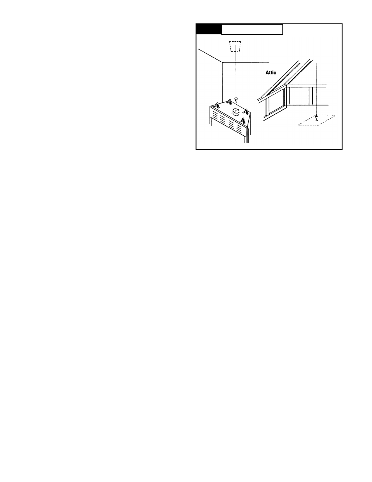
It is very important that you determine where the flue
(chimney) will go through the ceiling and roof. Check the
structure of yo ur home to see that the location you have
chosen will make installation as easy as pos sible. Using a
plumb bob, hold the string from the ceiling and drop it,
moving the string until the plumb bob is in the center of the
flue collar opening. See figure 3. Mark the spot on the
ceiling. You may wish to drive a nail through the ceiling at
this spot. Then go into the attic and find the nail. Using the
plumb bob with the ceiling nail as the center point of the
flue, mark the center of the area on the roof through which
the flue will pass. This is to see if it is possible to cut your
opening for the flue in both the ceiling and roof without
cutting either roof rafters or ceiling joists. A location that
requires cutting the least number of joists and rafters will
simplify the installation and reduce the cost. The structural
integrity of a home's floor, walls and ceiling roof must be
maintained. It is not recommended to cut roof trusses.
Figure 3 Use of the Plumb Bob
FIREBOX AND CHIMNEY SYSTEM
CLEARANCES
The fireplace may be placed directly on a combustible floor,
against a combustible wall at marked clearances, or on a
raised wooden platform.
If the fireplace is to be installed on a raised platform, the
platform must be a continuous level surface.
The fireplace must be secured in place so it cannot shift
positions. The nailing flanges on the sides of the firebox
make securing the firebox to the frame quick and easy. The
nailing flanges were designed to allow the installation of 1/2"
wallboard or ply wood flush with the face of the fireplace.
Only the header (see figure 4) may rest on the standoffs on
top of the firebox.
Combustible materials may not cover any part of the black
metal surrounding the firebox opening. See figure 4.
Do not install the firebox over vinyl floors or carpet.
Combustible floors in front and to the sides of the firebox
opening must be protected by a non-combustible hearth
extension as shown in figure 4.
CHIMNEY OUTLET
Thought should be given to the proposed location of the
chimney outlet on the roof. Objects such as trees, adjacent
buildings or embankments that are too close to the chimney
can create air circulation problems during windy weather
that could affect the way the fireplace draws air.
After careful consideration, choose the location for your
fireplace to achieve the simplest installation for maximum
efficiency.
5
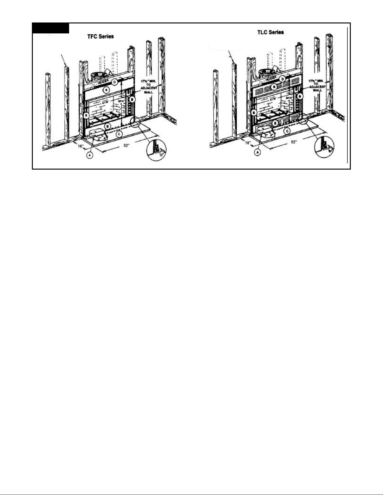
Figure 4
Framing Members
THE CAUTIONS BELOW RELATE TO LOCATIONS ON
FIGURE 4.
A. The hearth safety strip must be used under the crack
between the fireplace and the hearth extension when the
fireplace is installed on a combustible floor. Seal the
crack with a non-combustible material such as mortar,
grout, etc.
B. COMBUSTIBLE MATERIALS MUST NOT OVERLAP
THE SURFACE OF THE BLACK FRONT FACE
PANELS. COMBUSTIBLES MAY BE INSTALLED
OVER THE SIDE NAIL FLANGES UP TO THE EDGE
OF THE FRONT FACE SURFACE.
? DO NOT BLOCK HEAT CIRCULATING AIR INLETS
OR OUTLETS. DOING SO MAY RESULT IN A
POTENTIAL FIRE HAZARD.
C. If the floor in front of the fireplace is combustible, either a
raised or floor-level protective hearth extension must be
constructed. For TFC39 only, a raised hearth extension
may be flush with the fireplace hearth. To construct a
raised hearth extension with louvered models, the
fireplace must rest on a raised platform. A raised hearth
extension must be a minimum of 16" x 52" and be
constructed of materials with an R-factor equal to or
greater than 1.20. A hearth extension installed directly on
the floor must be a minimum of 16" x 52" and be
constructed of materials with an R-factor equal to or
greater than .80. If combustible materials are used to
construct the hearth extension, they must not touch the
black surface of the fireplace. The same material that is
used to protect the top of the hearth extension must be
placed between the combustible and the black face of
the fireplace. The hearth extension must be fastened to
the floor to prevent shifting and the gap between the
fireplace and the hearth extension must be sealed with a
noncombustible material if a metal safety strip is not
used. These materials (listed below) may be used for a
wall shield as well.
D. The framing header may rest on top of the standoffs.
E. The minimum distance from the fireplace opening to an
adjacent combustible wall is 17½". The minimum
distance to an adjacent combustible wall may be reduced
to 12" when an approved wall shield is used on the wall.
The wall shield must be 40" x 40" and be constructed of
a noncombustible, inorganic material having a thermal
Framing Members
resistance of R = 1.49.
Determining the R-Values
The hearth extension must be constructed of noncombustible materials which have a total thermal resistance
(R factor) equal to or greater than .80 for floor level hearth
extensions or 1.20 for raised hearth extensions and be a
minimum size of 16" x 52". Choose the desired materials
and obtain the K value at 75° mean temperature. The C
value and the R value may be calculated with the following
formulas:
K = Thermal conductivity. K = BTUs-ins./hrs.-ft.2-0F
T = thickness C= Thermal conductance
R = Thermal resistance K/T = C; 1/C = R
Example: 3/4" Marble with 3/8" Micore
Determine the R value for each material used as follows:
Marble:K/T= 11/.75=14.66.
1/C = 1/14.66 = 0.068 (R factor)
Micore 300: K/T = .458/.375 = 1.22.
1/C = 1/1.22=0.82 (R factor)
After the R value is obtained on each material in this hearth,
add the R values to obtain total thermal resistance (R).
Total R factor = 0.068 + 0.82=0.89
The total must be equal to or greater than specified above.
Typical materials: Micore 300 has a K of .458; Micore 230
has a K of .43; Micore 180 has a K of .34; Ceraboard has a
K of .34; common brick has a K of 5; cement mortar has a K
of 5; marble has a K of 11; limestone has a K of 6.5; tile has
a K of 12; slate has a K of 21; Wonder Board has a K value
of 3.2.
MICORE NC 180-300, manufactured by U.S. GYPSUM
CORPORATION
CONWED SPEC 300, manufactured by CONWED
CORPORATION
CERA FORM TYPE 106R board, manufactured by
JOHNS-MANVlLLE.
WONDER BOARD, manufactured by GOLD BOND
BUILDING PRODUCTS.
6
 Loading...