

TEMCO FIREPLACE PRODUCTS, Inc.
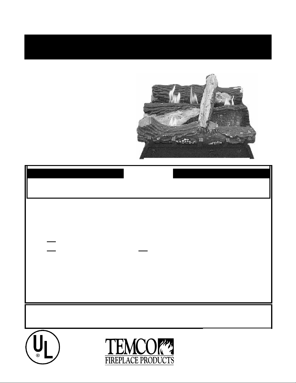
Installation and Operating Instructions for Gas Log Heaters
Models PS24MN, PS24MP
Models ending with “N” use natural gas; models ending with “P” use propane (LP) gas.
This appliance operates as an
unvented room heater certified under
ANSI Z21.11.2-2000 when fitted to a
solid fuel burning masonry or factory
built fireplace with the flue damper
closed. It also operates as a
decorative appliance under ANSI
Z21.60a-2000.CGA 2.26a-2000, when
fitted to a solid fuel burning masonry
or factory built fireplace with the flue
damper open. State or local codes
may only allow operation of this
appliance in a vented configuration.
WARNING
If the information in this manual is not followed exactly, a fire or explosion may result
FOR YOUR SAFETY
• Do not store or use gasoline or other flammable vapors and liquids in the vicinity
of this or any other appliance.
WHAT TO DO IF YOU SMELL GAS
• Do not try to light any appliance.
• Do not touch any electric switch; do not use any phone in your building.
• Immediately call your gas supplier from a neighbor's phone. Follow the gas
supplier’s instructions.
• If you cannot reach your gas supplier, call the fire department.
• Installation and service must be performed by a qualified installer, service agency
or the gas supplier.
This is an unvented gas-fired heater. It uses air (oxygen) from the room in which it is
installed. Provisions for adequate combustion and ventilation air must be provided.
GAS FIRED
UNVENTED
ROOM HEATERS
LISTED
5L24
PATENT NO. US 6,390.808 B1
P.O. Box 1349 Manchester, TN 37349
P.O. Box 1148 Perris, CA 92572
1773 Parque Industrial Cachanilla
Mexicali, B.C. 21600
REV. 10/30/02 10:05 AM 76780M
CONTENTS
Important Information ......................................................................................................................................................................Page 3,4
Provision for Adequate Combustion and Ventilation Air ....................................................................................................................4
Installation
Unpacking ..................................................................................................................................................................................................6
Fireplace preparation ................................................................................................................................................................................6
Location ......................................................................................................................................................................................................6
Clearances .................................................................................................................................................................................................6
Gas connection ..........................................................................................................................................................................................7
Piping Chart ...............................................................................................................................................................................................8
Gas pressure check ..................................................................................................................................................................................9
Log positioning ........................................................................................................................................................................................10
Fireplace screen ......................................................................................................................................................................................10
Decorative volcanic ash .........................................................................................................................................................................10
Unit operation
To turn off gas to appliance ...................................................................................................................................................................11
Managing heat output .............................................................................................................................................................................13
Flame check ............................................................................................................................................................................................12
Maintenance ...................................................................................................................................................................................................13
Troubleshooting ............................................................................................................................................................................................14
Repair Parts ....................................................................................................................................................................................................15
Parts List .........................................................................................................................................................................................................15
Warranty Information ...................................................................................................................................................................................16
Installation and Startup Checklist .....................................................................................................................................................17, 18
Warranty Registration ..................................................................................................................................................................................19
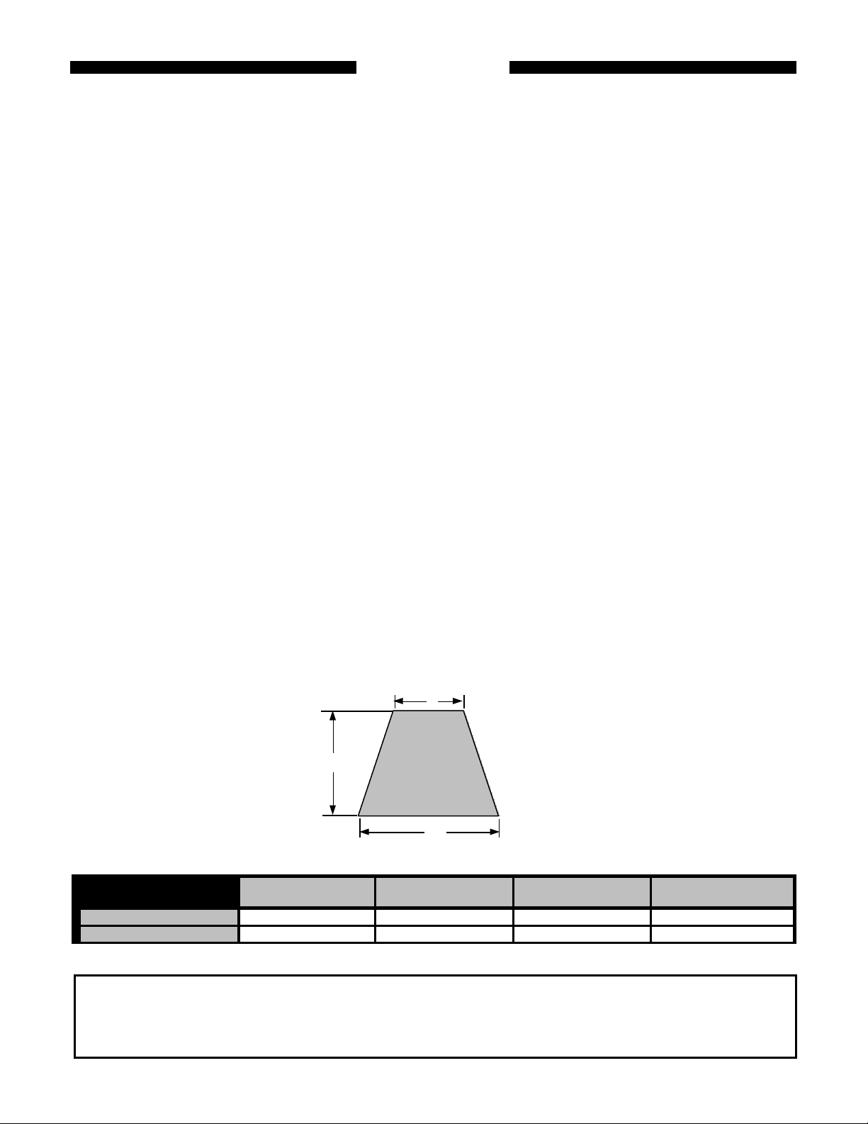
M INIMUM DIMENSIONS FOR EXISTING SOLID FUEL BURNING FIREPLACES.
B
OPENING HEIGHT = H
C
A
HEARTH SIZE TABLE Opening Height
(H)
PS24MN 18" 30" 21" 15"
PS24MP 18" 30" 21" 15"
This appliance may be installed in an aftermarket, permanently located, manufactured (mobile) home, where not
prohibited by local codes.
This appliance is only for use with the type of gas indicated on the rating plate. This appliance is not convertible for
use wi th other gases.
Front Width
(A)
Rear Width
(B)
Depth
(C)
2
IMPORTANT INFORMATION
INSTALLER: P lease leave these instructions with the owner.
OWNER: P lease retain these instructions for future reference.
WARNING: ANY CHANGE TO THIS HEATER OR ITS
CONTROLS CAN BE DANGEROUS.
IMPORTANT: READ THESE INSTRUCTIONS CAREFULLY
BEFORE INSTALLING.
NOTES
• Due to high temperatures, the appliance should be
located out of traffic and away from furniture and
draperies.
• Installation and repair should be done by an
experienced and qualified service person or gas
appliance installer.
• The appliance must be inspected before use and at
least annually by a professional service person. More
frequent cleaning may be required due to excessive lint
from carpeting, bedding material, dust and pet hair, etc.
It is important that the control compartment, burners
and circulating air passageways of the appliance be
kept clean. Refer to instructions on Page 13.
• DO NOT place clothing or other flammable material on
or near the appliance.
• This appliance must only be used with pressures at the inlet
as shown in Table 1, page 10. Failure to check and
document these pressures may void the warranty.
• The installation must conform with local codes or, in the
absence of local codes, with the NATIONAL FUEL GAS
CODE, ANSI Z223, latest edition. If you cannot reference
these codes, DO NOT attempt to install this unit.
• Any safety screen or guard removed for servicing an
appliance must be replaced prior to operating the
heater.
• The appliance and its appliance main gas valve must be
disconnected from the gas supply piping system during any
pressure testing of that system at test pressures in excess
of 1/2 PSIG (3.5 kpa).
• The appliance must be isolated from the gas supply piping
system by closing its equipment shut-off valve during any
testing of the gas supply piping system at test pressures
equal to or less than 1/2 PSIG.
• DO NOT use this heater in recreational vehicles, bedrooms
or bathrooms.
• If this is the ONLY gas appliance, we recommend a
minimum 200 pound cylinder with a fill gauge. Use of a 100
pound cylinder is not recommended. Other household gas
appliances may require the tank size to be larger. Do not
operate the vent-free heater if the fuel level in the propane
tank is below 1/4 full.
• DO NOT use this heater if any part of it has been
submerged under water. Immediately call a qualified
technician to inspect the appliance and replace any part of
the control system and any gas control which has been
under water.
• Any outside air ducts in the fireplace shall be permanently
closed at the time of appliance installation.
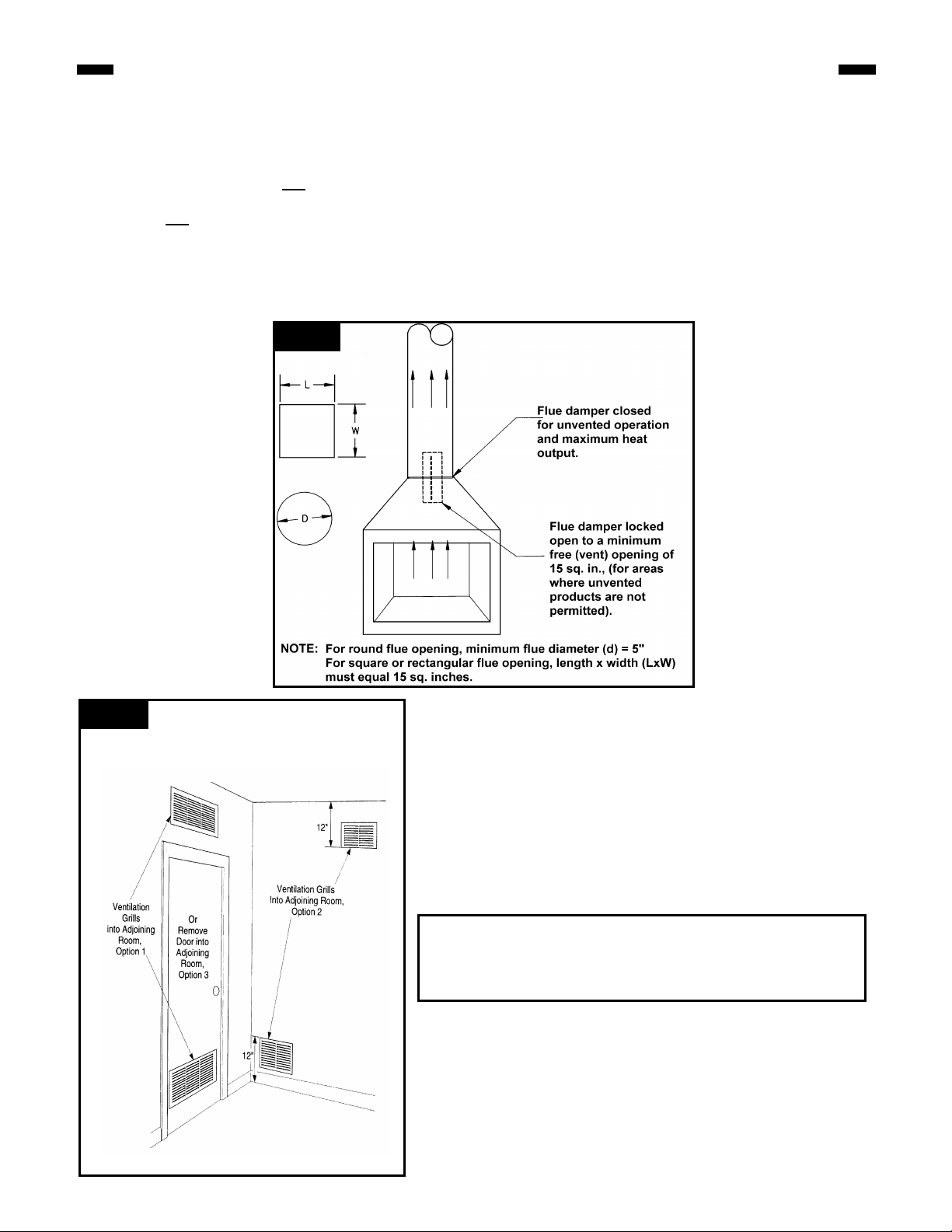
• Check local, state or city codes to determine if unvented
heaters are permitted. If unvented heaters are not
permitted, the fireplace chimney damper must be fixed
at a minimum free (vent) opening area of 15 sq. ins.
This must be accomplished by a clamp or screw on the
chimney damper to stop at the minimum vent area. The
fireplace must also have a minimum free (vent) opening
of 15 sq. ins., (see figure 1).
• This appliance may be installed in an after-market*
manufactured "mobile" home where not prohibited by state
or local codes.
• *After-market: Completion of sale, not for purpose of re-
sale from the manufacturer.
• OUTSIDE AIR DAMPER OR ASH DUMP (IF PRESENT)
MUST BE CLOSED AND SEALED.
• Young children should be carefully supervised when
WARNING: Do not allow fans to blow directly into the
fireplace. Avoid any drafts that alter burner flame
patterns to prevent property damage.
WARNING: Do not use a blower insert, heat
exchanger insert or other accessory not approved for
use with this heater.
WARNING: During manufacturing, fabricating and
shipping, various components of this appliance are
treated with certain oils, films or bonding agents.
These chemicals are not harmful but may produce
annoying smoke and smells as they are burned off
during the initial operation of the appliance, possibly
causing headaches and eye/lung irritation. This is a
normal and temporary occurrence.
WARNING: This appliance is for installation only in a
solid-fuel burning masonry or UL 127 factory-built
fireplace or in a listed ventless firebox enclosure. It
has been designed certified for these installations.
Exception: DO NOT install this appliance in a factorybuilt fireplace that includes instructions stating it has
not been tested or should not be used with unvented
gas logs.
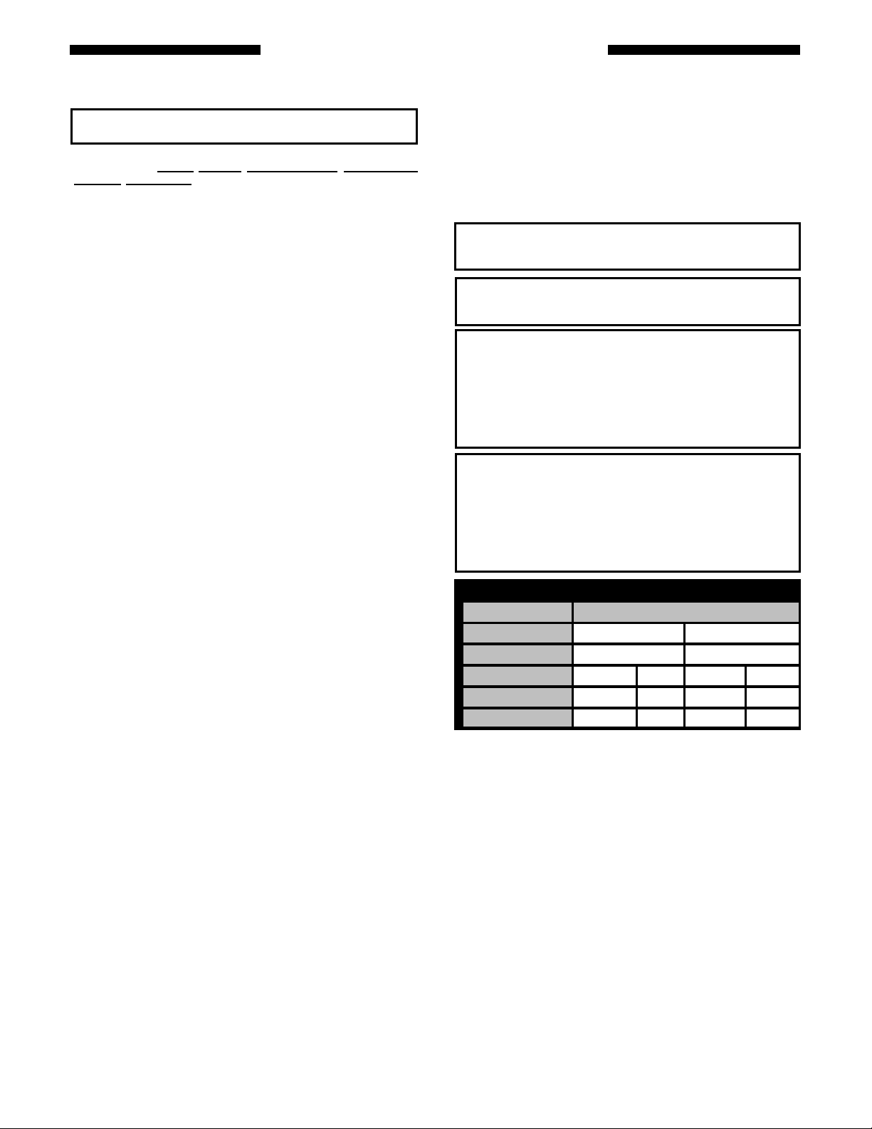
PS24 SERIES BTU / HR INPUT
GAS BURNER OPERATION
REAR BURNER
FRONT & REAR
HIGH LOW HIGH LOW
ONLY
NATURAL 40,000 22,000 25,500 19,000
LP (PROPANE) 40,000 24,000 25,500 19,000
they are in the same room as the appliance.
• An unvented room heater having an input rating of more
than 10,000 btu per hour shall not be installed in a
bedroom or a bathroom.
FOR INSTALLATION OF HIGH ALTITUDE
When installing this fireplace at an elevation above 2,000 feet
(in the United States), it may be necessary to decrease the
input ratin g by changing the existing burner orifice to a smaller
size. Input should be reduced four percent (4%) for each 1,000
feet above sea level, unless the heating value of the gas has
been reduced, in which case this general rule will not apply. to
identify the proper orifice size, check with the local gas utility.
Consult your local gas utility for assistance in determining the
proper orifice for your location.
Ref. No. Description
3
PROVISIONS FOR ADEQUATE COMBUSTION AND VENTILATION AIR
WARNING: This heater shall not be installed in a
confined space or unusually tight construction unless
provisions are provided for adequate combustion
ventilation air.
The National Fuel Gas Code, ANSI Z223.1 defines a
confined space as a space whose volume is less
than 50 cubic feet per 1,000 Btu per hour (4.8m3
per kw) of the aggregate input rating of all
appliances installed in that space and an
unconfined space as a space whose volume is not
less than 50 cubic feet per 1,000 Btu per hour (4.8
m3 per kw) of the aggregate input rating of all
appliances installed in that space. Rooms
communicating directly with the space in which
the appliances are installed, through ope nings not
furnished with doors, are considered a part of the
Today's homes are built more energy efficient than ever.
New materials, increased insulation and new construction
methods help reduce heat loss in homes. Home owners
weather strip and caulk around windows and doors to keep
the cold air out and the warm air in. During heating months,
home owners want their homes as airtight as possible.
While it is good to make your home energy efficient, you
need fresh air. All fuel-burning appliances need fresh air for
proper combustion.
SUPPLYING ADEQUATE VENTILATION
This appliance must be installed in an unconfined space.
The following information will help you classify yo ur space
and provide adequate ventilation for complete combustion.
An Unconfined Space has a minimum volume of 50 cubic
feet for each 1000 BTU/Hr input rating of all appliances in
the space. (4.8 m3 per kw), (cubic feet equals length x width
x height of space).
A Confined Space has a volume of less than 50 cubic feet
for each 1000 BTU/Hr input rating of all appliances in the
space, (4.8 m3 per kw), (cubic feet equals length x width x
height of space).
DETERMINING IF YOU HAVE A CONFINED OR
UNCONFINED SPACE.
Use this worksheet to determine if you have a confined or
unconfined space.
Space: Includes the room in which you will install heater
plus any adjoining rooms with doorless passageways or
ventilation grills between the rooms.
1. Determine the volume of the space (length x width x
height).
? Length x Width x Height = _____cu. ft. (volume of space)
? Example: Space size 25 ft. (length) x 25 ft. (width) x 8 ft.
(ceiling height) = 5,000 cu. ft. (volume of space)
? If additional ventilation from adjoining room(s) is supplied
with grills or doorless openings, add the volume of these
rooms to compute the total volume of the applicable
space.
2. Divide the space volume by 50 cubic feet to determine
the maximum BTU/Hr the space can support.
? ________(volume of space) ÷ 50 cu. ft. = (Maximum
BTU/Hr the space can support.
? Example: 5,000 cu. ft. (volume of space) ÷ 50 cu. ft. =
100 or 100,000 (maximum BTU/Hr the space can
support)
3. Add the BTU/Hr of all gas burning appliances in the
space.
Gas range ________________BTU/Hr
Vented gas heater __________BTU/Hr
Gas fireplace logs ___________BTU/Hr
Other gas appliances* + ______BTU/Hr
Total = _____BTU/Hr
Example: Gas range 60,000 BTU/Hr
Vent-free logs +29,000 BTU/Hr
Total =89,000 BTU/Hr
? *Do not include direct-vent gas appliances. Direct-vent
draws combustion air from the outdoors and vents to the
outdoors.
4. Compare the maximum BTU/Hr the space can support
with the actual amount of BTU/Hr used.
? __________ BTU/Hr (maximum the space can support)
? __________ BTU/Hr (actual amount of BTU/Hr used)
Example: 100,000 BTU/Hr (maximum the space can
support) 89,000 BTU/Hr (actual amount of BTU/Hr used)
The space in the above example is an unconfined space
because the actual BTU/Hr used is less than the maximum
BTU/Hr the space can support. If the space had been
confined, your options would be as follows:
A. Rework worksheet, adding the space of an adjoining
room. If the extra space provides an unconfined space,
remove door to adjoining room or add ventilation grills
between rooms. See Ventilation Air From Inside
Building.
B. Install a lower BTU/Hr heater, if lower BTU/Hr size
makes room unconfined.
CONVERTING CONFINED SPACE TO UNCONFINED
SPACE.
Additional volume to convert a confined to an unconfined
space could come from an adjoining space. When using an
adjoining spac e, you can provide two permanent openings:
one within 12" of the ceiling and one within 12" of the floor
on the wall connecting the two spaces (see options 1 and 2,
figure 2), or remove the door into the adjoining room.
VENTILATION AIR FROM OUTDOORS FOR
UNUSUALLY TIGHT CONSTRUCTION.
WARNING: If the area in which the heater may be
operated is smaller than that defined as an unconfined
space or if the building is of unusually tight
construction, provide adequate combustion and
ventilation by one of the methods described in the
National Fuel Gas Code, ANSI Z223.1/NFPA 54, Section
5.3 or applicable codes.
4
PROVISIONS FOR ADEQUATE COMBUSTION AND VENTILATION AIR
Unusually tight construction is defined as construction
where:
a. walls and ceilings exposed to the outside atmosphere
have a continuous water vapor retarder with a rating of
one perm (6 x 10.11 kg per pa-sec-m2) or less with
openings gasketed or sealed and
b. weather stripping has been added on openable windows
and doors and
c. caulking or sealants are applied to areas such as joints
around window and door frames, between sole plates
and floors, between wall-ceiling joints, between wall
panels, at penetrations for plumbing, electrical and gas
lines and at ot her openings.
Figure
If your home meets all of the three criteria above, you must
provide additional fresh air.
You may provide two permanent openings: one within 12"
of the ceiling and one within 12" of the floor. Connect these
items directly to the outdoors or spaces open to the
outdoors. These spaces include attics and crawl spaces.
Follow the National Fuel Gas Code NFPA 54/ANSI Z223.1,
Section 5.3, Air for Combustion and Ventilation for required
size of ventilation grills or ducts.
IMPORTANT: Do not provide openings for inlet or outlet air
into attic if attic has a thermostat-controlled power vent.
Heated air entering the attic will activate the power vent.
Figure 2 Ventilation Air from Inside
WARNING: Air openings that provide fresh air from an adjoining
unconfined space shall not be blocked or obstructed in any way.
Installation of unit should allow a minimum of 2" clearance from
any part of the heater to any of the ventilation openings.
5
INSTALLATION
UNPACKING
Open the carton and remove the logs and the chassis.
Remove each of the logs by gripping at either end of the log
while avoidin g any undue pressure.
The carton for each model contains the following: grate/
burner assembly, front,middle and rear logs, top twig, 2
screws, 2 brackets and a bag of volcanic ash.
FIREPLACE PREPARATION
The fireplace needs to be prepared before installing the
unit:
A. Turn off the gas supply if the gas line has been run to the
fireplace.
B. WARNING: Before installing in a solid fuel burning
fireplace, the chimney flue and firebox must be
cleaned of soot, creosote, ashes and loose paint by a
qualified chimney cleaner.
? Note: If your fireplace has been cleaned using chemi-
cals or solvents, these products may have been
absorbed into the fireplace hearth and walls and will be
burned off during the initial break-in period.
C. Any outside air ducts and/or ash dumps in the fireplace
shall be permanently closed and sealed at the time of
appliance installation. This will prevent drafts from
disturbing the flames and interfering with complete
combustion of the gas fuel.
LOCATION
When gas logs are to be installed in a fireplace, inspect the
area surrounding it for possible air drafts that may affect the
flames and possibly cause sooting. Such drafts may be
caused by a ceiling fan near the fireplace, a hot air furnace
register or an open door. When burning the logs, carefully
observe the effect of possible drafts on the flames and take
appropriate measures to eliminate them. For example, the
ceiling fan may be cut off, the hot air register closed, etc.
Centrally locate the gas logs in the fireplace deep enough
into the firepit to accomplish an adequate draft (if use as a
vented appliance is planned). Ensure that the grate’s front
feet sit inside the front edge of the fireplace. Be sure
fireplace meets minimum fireplace dimensions.
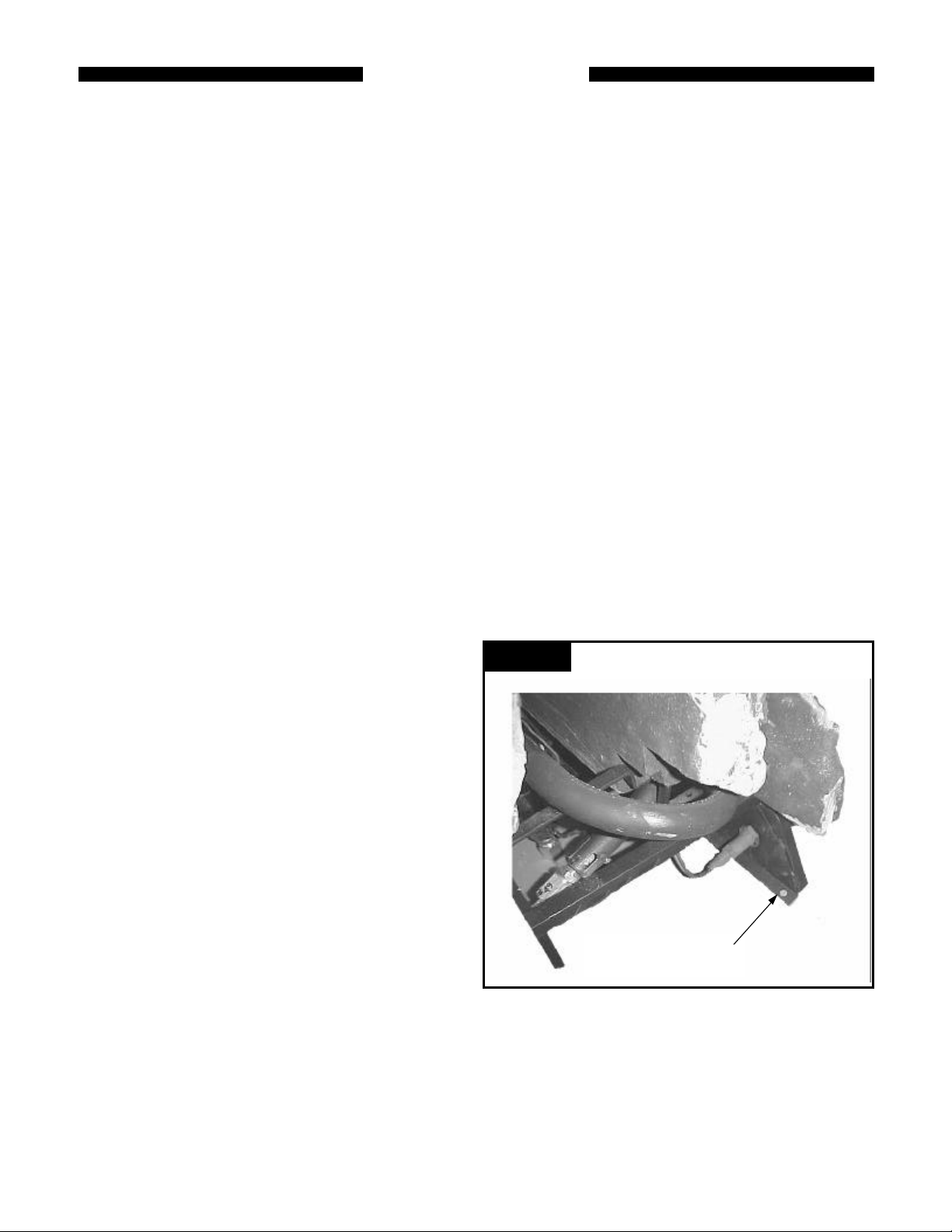
To avoid any movement of the unit during operation,
screw the chassis to the floor of the fireplace using the
screws provided. Failure to do so could cause gas
leaks.
Holes are provided just behind the front grate legs, and
should be used for securement of the log set. After locating
the chassis correctly in the fireplace, mark the hole
positions on the fireplace floor. Drill two 1/8” diameter holes
approximately 1/2" deep.
Use the two screws to secure the chassis to the fireplace
floor, (see figure 3).
is inadvertently closed.
Clearances for Unvented Installation in existing
fireplaces, (jurisdiction permitting)
1. Sidewall Clearances: Clearances from the side of the
fireplace opening to any combustible wall should not be
less than 2". (see figure 4A and 4B).
2. Ceiling Clearances: The ceiling height should not be
less than 62" from the fireplace hearth. (see figure 4A).
3. Mantel Clearances: The use of a canopy* is optional
depending on mantel clearances to the fireplace opening
and projection profile. (see figure 4C and 4D).
? NOTE: Mantel clearances may differ for each vent-free
firebox. Refer to the firebox installation instructions for
clearances.
A. Mantel profile: The minimum distance above the
fireplace opening to combustible material projecting 11/2 ” (tile moldings, breast boards, etc.) is 12-1/2".
? Combustible material projecting 6" (a mantel shelf, for
example) requires a minimum clearance of 19" above
the fireplace opening. Required clearance varies with
the amount of projection, (see figure 4C).
? The mantel profile must fall within the cross -section
shown in figure 4C or 4D.
B. Heat resistant material: Any heat resistant material
suitable for a continuous operating temperature of
120°C (248°F) must cover the wall surface directly
above the fireplace openin g and extend the full width
of the fireplace opening for a distance of 10" above
the opening. (see figure 4C).
Figure 3
CHASSIS SECUREMENT
LOCATION.
CLEARANCES
NOTE: The following instructions regarding installation
clearances and the use and installation of a canopy apply to
use of the appliances as an unvented space heater in
permitting jurisdictions. When installed as a vented
decorative gas appliance, the clearances noted below and
the use of a heat -deflecting canopy are not required.
However, it is recommended that these instructions be
followed even when the appliance will be used as a vented
decorative appli ance in case local codes change to allow
unvented space heaters or in the event that the flue damper

Figure 4A:
Minimum Clearance to Wall & Ceiling
62”
Figure 4C:
MANTEL CLEARANCES (SINGLE OR MULTI- SIDED OPENING FIREPLACES)
Figure 4B:
2”
Side Clearances and Projection
FIREPLACE
HEARTH
LEVEL
GAS CONNECTION
CHECK GAS TYPE. Use only the gas type indicated on the
heater's rating plate. If the gas type indicated on the plate
is not yo ur type of gas supply, DO NOT INSTALL. Contact
your dealer for the proper model.
WARNING
DANGER OF PROPERTY DAMAGE,
BODILY INJURY OR DEATH.
MAKE SURE THE HEATER IS EQUIPPED TO
OPERATE ON THE TYPE OF GAS AVAILABLE.
MODELS DESIGNATED AS NATURAL GAS ARE TO
BE USED WITH NATURAL GAS ONLY. HEATERS
DESIGNATED FOR USE WITH LIQUEFIED
PETROLEUM (L.P.) GAS HAVE ORIFICES SIZED
FOR COMMERCIALLY PURE PROPANE GAS.
THEY CANNOT BE USED WITH BUTANE OR A
MIXTURE OF BUTANE AND PROPANE.
GAS PIPING. The gas supply line must be of an adequate
size to handle the BTU/HR requirements and length of the
run for the unit being installed.
Determine the minimum pipe size from the piping size chart
on page 9. The normal gas connection at this appliance is
1/2" NPT made at the left of the unit.
Always use an an external regulator for all LP installations
to reduce the supply tank pressure to a maximum of 14"
Figure 4D:
WC. This is in addition to the regulator fitted to the heater.
All piping must comply with local codes and ordinances or with
the National Fuel Gas Code (ANSI Z223.1), whichever applies.
GAS CONNECTION. If installation is for L.P. gas, have L.
P. installer use two-stage regulation and make all
connections from storage tank to heater. Refer to the
National Fuel Gas Code for the proper supply tank size with
the Btu's/Hr requirements. If this is the ONLY gas
appliance, we recommend a minimum 200 pound cylinder
with a fill gauge. Use of a 100 pound cylinder is not
recommended. Other household gas appliances may
require the tank size to be larger.
Use pipe wrenches when making the connection to the
valve to prevent turning or damage to gas valve.
Connection between the manual shutoff valve and the gas
valve can be made with an CSA design certified flexible
connector if allowed by local codes. A drip leg (sediment
trap) must be installed, (see figure 5). Tighten all joints
securely.
CAUTION: Failure to install a drip leg (sediment trap)
may result in improper combustion that will produce
soot. Reference Sections 3.7 and 5.5.7 and Figure 5.5.7
of the National Fuel Gas Code for guidance.
WARNING: Connecting directly to an unregulated
LP tank can cause an explosion.
7

Figure 5
PIPED GAS SUPPLY
LESS THAN 6 FEET
IF USING FLEXIBLE CHECK
LOCAL CODES FOR SPECIFIC
REQUIREMENTS
GAS
VALV
All bends in metallic tubing should be smooth, elbows are
recommended.
CAUTION: Shut off the main gas supply before removing end
cap to prevent gas from filling the work area. Test for gas
leakage when installation is complete.
Under no circumstances should internally zinc alloy coated piping be used. According to the LP-Gas Code and
National Fuel Gas Code - If galvanized piping is used, it must be EXTERNALLY coated only! Galvanized water pipe
used for gas installations will result in reduced gas pressure and gas leaks.
8

GAS LINE PIPE SIZING
NOTE: To determine the size of the branch gas line from the main gas line to the fireplace, enter the
tables below (for iron pipe or copper tubing) using the distance from the gas meter or second
stage regulator to the furthest appliance on the gas system. Select a pipe or tube diameter which
has enough capacity to meet the maximum input requirement of the fireplace. Regardless, do not
use less than 1/2" diameter for the branch line. For any distances required longer than sho wn in
NOTE: There may be a local gas utility requirement specifying a minimum diameter for gas piping. All units require a 1/2 inch pipe connection at the
gas valve.
Length
Pipe Natural Propane Natural Propane Natural Propane Natural Propane Natural Propane
100' 38 59 79 122 150 235 305 474 460 717
WARNING: Use only internally tinned copper tubing. If correct copper tubing is not used, tubing can deteriorate
and develop gas leaks.
GAS PRESSURE CHECK
Check the inlet pressure to the appliance to ensure that it is
as shown in Table 1. Also check the incoming gas
pressure where the field installed gas line connects to the
gas logs.
Gas Inlet Pressure Natural Propane
Regulator Pressure 4.5 ins. WC 10 ins. WC
*Minimum inlet supply pressure for the purpose of input adjustment
The manifold pressure is controlled by the gas valve and
should be checked at the pressure test point located near
the outlet end of the combination control.
The pressure should be checked with the appliance burning
on high (highest setting) and all other appliances turned on.
One mus t then read the manometer and if pressures are
not 10.0” W.C. for LP or 4.5” W.C. for Natural gas the inlet
pressure must be adjusted or increased until the proper
pressures are attained. If these pressures are greater than
10.2” W.C. for LP or 4.7” W.C. for Natural gas, contact your
these tables, refer to the National Fuel Gas Code.
Cubic Feet per Hour based on 0.3" W.C. Pressure Drop
Specific Gravity for Natural Gas - 0.6 (1000 BTU/Cubic Foot)
Specific Gravity for Propane Gas - 1.6 (2550 BTU/Cubic Foot)
NOMINAL INCHES FOR IRON PIPE SIZES (1,000s BTU/Hr)
of 1/2" D 3/4" D 1" D 1¼" D 1½" D
20' 92 143 190 296 350 546 730 1135 1100 1711
30' 73 115 152 237 285 444 590 918 890 1385
40' 63 97 130 202 245 380 500 778 760 1183
50' 56 87 115 179 215 334 440 683 670 1043
60' 50 79 105 163 196 304 400 622 610 949
70' 46 71 96 151 180 280 370 576 560 872
90' 40 61 84 130 160 250 320 497 490 763
Outside Diameter Copper Tubing, Type L (1,000s BTU/Hr)
Tubing
Length
Feet
1/2"
0.43
10 110 206 348 536
20 76 141 239 368
30 61 114 192 296
40 52 97 164 256
50 46 86 146 224
60 42 78 132 203
80 36 67 113 174
100 32 59 100 154
Table 1
Max. 10.5 ins. WC 13 ins. WC
Normal 7.0 ins. WC 11 ins. WC
Min.* 5.5 ins. WC 10.8 ins. WC
CAPACITY OF PIPING
5/8"
0.545
gas supplier before operating the appliance.
After measuring the pressure, replace the test point plug
and check for leaks.
CAUTION: If the appliance's operating pressures are
not checked and adjusted, improper combustion may
result in soot being produced. Record the results of
the gas pressure check on the appropriate documents.
TESTING THE GAS PIPING. Test all piping for leaks.
When checking gas piping to the heater with gas pressure
less than 1/2 PSI, shut off manual gas valve for the heater.
If gas piping is to be checked with the pressure at or above
1/2 PSI, the heater and manual shut off valve must be
disconnected during testing to prevent damage to the
regulator on the unit. (SEE WARNING).
To ensure that the gas lines and connections do not have
any leaks, a pressure test should be performed. Only a
qualified installer should perform the pressure test to
ensure that the unit is not damaged by high pressures!
WARNING: Be sure that the gas type indicated on
the gas log rating plate concurs with the gas
system in your building.
3/4"
0.666
7/8"
0.785
9

WARNING
DANGER OF PROPERTY DAMAGE,
BODILY INJURY OR DEATH.
NEVER USE A MATCH OR OPEN FLAME TO TEST FOR
LEAKS. NEVER EXCEED SPECIFIED PRESSURES FOR
TESTING. HIGH PRESSURES MAY DAMAGE THE
APPLIANCE REGULATOR WHICH WOULD REQUIRE
REPLACEMENT. LIQUID PETROLEUM (L.P.) IS HEAVIER
THAN AIR AND IT WILL SETTLE IN ANY LOW AREA,
INCLUDING OPEN DEPRESSIONS AND IT WILL REMAIN
THERE UNLESS AREA IS VENTILATED.
NEVER ATTEMPT START-UP OF UNIT BEFORE
THOROUGHLY VENTILATING AREA.
If you connect natural gas to an LP gas unit, you may be
unable to ignite the pilot. If the pilot does ignite, the front
burner flame on the low setting will be bright blue but only
1/4” to 1/2” long and most likely lifting off the burner ports. If
this is the case, turn the unit off immediately and contact the
dealer wher e the unit was purchased.
If you connect LP gas to a natural gas unit, the front
burner flame on the low setting will be about 6” - 8” long. On
the medium and high setting, the front burner flames wi ll be
bright yellow and about 10” in length. Turn the unit off
immediately! If the unit is allowed to run in this condition,
substantial amounts of soot will be generated and emitted
into the house. contact the dealer where the unit was
purchased.
POSITIONING LOGS
1.Unpack and identify the four (4) logs by referring to Figures
6A, 6B and 6C.
2.Position back log into “V” log retainers ensuring that back
grate uprights are positioned in log notches.
3.Position front log with front grate bars fitting into log notches.
Log must fit down onto grate bars. (No gap under log).
4.Position middle log so notches in log fit snugly onto log
retaining bars. NOTE: Pin on left hand side of grate prevents
log from moving forward which would create flame
impingement from the yellow flame burner.
5. Position log retaining clip parallel with back edge of
middle log. Push pointed end of clip into log and fasten
clip to bar with screw provided. NOTE: This clip
maintains upright position of middle log to optimize
glowing ember front surface. (See clip location in Figure
6A).
When you have completed these steps, compare log
positions with Figure 6A. The logs must be positioned as
illustrated.
The top twig may be positioned as shown in either Figure
6B or Figure 6C.
The top twig must be placed in the notches provided on top
of the rear and center logs. The front of the top twig is to
rest of the large knot on the front log.
Caution: Proper location is critical. When positioning the
log set, make sure that the logs do not interfere with the
sides of the fireplace before securing the chassis.
FIREPLACE SCREEN
A fireplace screen must be in place when the appliance
is operating and unless other provisions for combustion air
are made, the screen must have openings for the
introduction of combustion air.
DECORATIVE VOLCANIC ASH
The volcanic ash from the bag provided should be sprinkled
Figure 6A
ash on burner, pilot or logs.
Figure 6B
WARNING: Failure to position the parts in
accordance with this diagram o r failure to use only
parts specifically approved with this heater may
result in property damage or personal injury. See
instruction manual for further information.
Figure 6C
WARNING: Failure to position the parts in
accordance with this diagram or failure to use only
parts specifically approved with this heater may
result in property damage or personal injury. See
instruction manual for further information.
10
around the base of the logset DO NOT place
any material, including volcanic
LOG POSITIONING - TOP VIEW
(ALTERNATE)
TWIG TOP POSITIONING - TOP VIEW
LOG
RETAINING
CLIP

Figure 7
OFF
FOR YOUR SAFETY READ BEFORE LIGHTING
WARNING: If you do not follow these instructions exactly, a fire or explosion may result
causing property damage, personal injury or loss of life.
A. This appliance has a pilot which must be lighted by hand. When
lighting the pilot, follow these instructions exactly.
B. BEFORE OPERATION smell all around the appliance area for
gas. Be sure to smell next to the floor
because some gas is heavier than air
and will settle on the floor.
WHAT TO DO IF YOU SMELL GAS:
• Do not try to light any appliance.
• Do not touch any electrical switch; do
not use any telephone in your building.
Figure 8
PIEZO
• Immediately call your gas supplier from a neighbor's telephone.
LIGHTING INSTRUCTIONS
1. STOP! Read “FOR YOUR SAFETY READ BEFORE LIGHTING”
before proceeding.
2. Refer to figure 9. To turn off the gas
supply, depress the knob slightly and turn
clockwise to the OFF
position.
3. Wait five (5) minutes to clear out any gas. If
you then smell gas, STOP! follow “B”, in the
safety information above. If you don’t smell
gas, go on to the next step.
4. Refer to figure 10. Locate the pilot. It is in the center of the back
burner.
5. Refer to figure 11. Push in the control knob and turn
counterclockwise to the PILOT position.
Hold the control knob in for a few
seconds
6. While still holding in the control knob,
press the ignitor push -button several
times. This will cause a spark at the pilot
which will ignite the pilot gas.
Refer to figure 11. Hold the contro l knob for 20 seconds to prevent the
flame failure detector from shutting off the gas while its probe is
Figure 9
Figure 10
• Follow the gas supplier's instructions.
• If you cannot reach your gas supplier, call the fire department.
C. Use only your hand to push in or turn the gas control knob. Never
use tools. If the knob will not push in or turn by hand, don't try to
repair it. Call a qualified service technician. Force or attempted
repair may cause a fire or an explosion.
E. Do not use this appliance if any part of it has been under water.
Immediately call a qualified service technician to inspect the
appliance and to replace any part of the control system or gas
control which has been under water.
Release the control knob. If the knob does not pop up when
released, stop and immediately call your service technician.
If the pilot will not stay lit after several tries, turn the gas
control knob to OFF and call your service technician or gas
supplier.
When the pilot remains lit, turn gas knob
counterclockwise to the HIGH position.
Depress the knob slightly and turn
counterclockwise to the setting you
prefer.
The front burner may be turned on
or off. Turn knob located on right
hand side of the control panel to
“ON” or “OFF” position. Do not
leave in an intermediate position.
This appliance is fitted with a
transient pilot burner for the sole
purpose of safe, momentary ignition of the main burner in
conjunction with the piezo ignitor. When in operation with the
main burner it contributes to the base heat release and is
turned off by turning the control knob to the OFF position.
The control knob should not be left at the ignition setting
after the pilot has been ignited.
Figure 11
TO TURN OFF GAS TO THE APPLIANCE
Depress the control knob slightly and turn it Clockwise to the OFF position. Refer to Figure 9.

IMPORTANT SAFEGUARDS
Although your gas logs are very realistic in
appearance it is not a real wood-burning fireplace and
must be used for burning rej ected material.
To avoid irreparable damage to the appliance or personal
injury; matches, paper, garbage or any other material
must not be placed or thrown on top of the logs or into the
flames.
To avoid personal injury, do not touch hot surfaces
when the appliance is operating.
Touch only the piezo button and control knob. Avoid
contact with the front screen, canopy or any other part
which will be very hot.
Always ensure that the fireplace screen is in place
when the appliance is operating.
Close supervision is necessary when the appliance is
being operated near children.
Do not use to cook food.
If this is the ONLY gas appliance, we recommend a
minimum 200 pound cylinder with a fill gauge. Use of a
100 pound cylinder is not recommended. Other household
gas appliances may require the tank size to be larger. Do
MATCH LIGHTING
If the pilot cannot be ignited with the piezo, it can be
manually lit with the use of a match and lighter rod.
1. Place the match in the holder and light. With the right
hand, depress and turn the control knob
counterclockwise to the PILOT position. Hold in
not operate the vent free fireplace if the fuel level in the
propane tank is below 1/4 full.
WARNING: The glowing ember base and all the logs
are manufactured from bonded ceramic fiber. This
is a commonly used material in industry worldwide.
In the event of the logs and base being removed,
care should be taken not to damage the bonded
material.
Intentional misuse of, or deliberately fragmenting,
the material could lead to inhaling fibers and be
injurious to health. Insure the logs are properly
This appliance is intended to be used only for
supplemental heat. Do not use it routinely as a primary
heat source. Continuous operation could produce
excessive humidity depending on construction
characteristics and outdoor temperatures (below 200F)
Over time, this could cause condensation to form and
damage wall structures and exterior paint. Do not use this
product duri ng building construction. Dust, debris, paint
2. Take the lighter rod and lighted match and ignite the
pilot.
3. Continue to hold the control knob for an additional 20
seconds to ensure pilot is maintained.
4. Proceed with step 8 in lighting instructions on page 11.
FLAME CHECK
A periodic visual check of the flames should be made. The
pilot flame should always be present when the appliance is
in operation. See figure 22.
In normal operation (at full rate for approximately 15 minutes) the following flame appearance should be observed:
Front Blue Flame Burner: The flame should burn blue
with absolute minimal to no yellow flames visible. Height of
flame should be approximately 3” on high.
Figure 21
Figure 23
Rear Yellow Flame Burner: The flame should be yellow in
color and should extend 6 to 8 inches above the large front
logs.
Typical flame shape as seen in Figure 22.
NOTE: For your safety, the appliance is equipped with an
oxygen depletion system. The system senses the oxygen in
the atmosphere and switches off the gas supply in case the
level of oxygen falls below a safe level. It must not be
altered in any way.
Figure 22
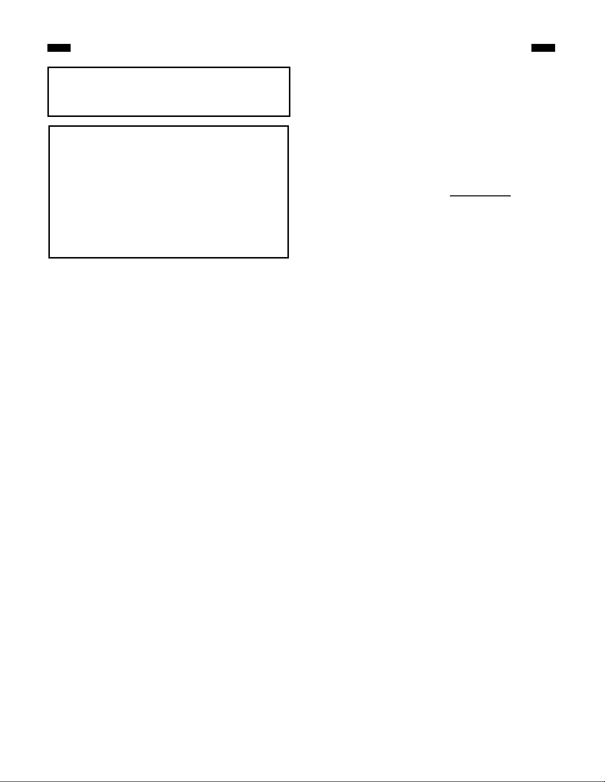
AIR SHUTTER SETTINGS - DIM “A”
“A
MODEL BLUE FLAME
FRONT BURNER
PS24MN
PS24MP .437 .250
12
.250 CLOSED
YELLOW FLAME
REAR BURNER

MANAGING HEAT OUTPUT
The heat output from the appliance can be controlled by the
position of the flue damper on vented fireplaces.
The damper setting should be fully closed for maximum
heat output, partially closed for less heat output and fully
open for minimum heat output.
The appliance may be used in a working solid fuel burning
fireplace with the fuel damper closed only if unvented
appliances are permitted by local state and city codes. It
may also be operated as a decorative appliance whose
The heat output from the appliance when operated as a vent -free heater may be controlled by adjusting the main
gas valve and by turning the front (blue flame) burner on or off. Reference lighting instructions on page, and chart
on page 3. showing inputs at all the settings.
The main gas valve may be adjusted anywhere between high and low to give the desired combination of flame
aesthetics and heat output. The blue flame front burner control must be turned fully to either the “ON” or “OFF”
position.
prime function lies in the aesthetic effect of the flames when
installed in a solid fuel burning fireplace with the flue
damper open. If unvented heaters are not permitted, the
fireplace vent damper must be locked at a minimum free
(vent) area of 15 sq. ins.
Whenever the appliance is operated with the fireplace's
flue damper closed, glass doors - if present - must be
open and the outside air damper and the ash dump (if
the fireplace is equipped with either one) must be
closed.
MAINTENANCE
CLEANING
CAUTION: Before cleaning or moving logs or other parts of
the unit, be sure to read the section on important
safeguards.
Cleaning should be done before the logs are used each
year and after long periods of non-use. Professional
servicing is recommended.
All cleaning should be carried out when the appliance is
cold.
Only limited cleaning will be required under normal use.
Dusting the front grate or the control knob panel may be
required occasionally. Do not use any cleaning fluids to
clean the logs or any other part of the appliance.
If the flames show any unusual shapes or behavior, or if the
burner(s) fail to ignite properly, then the burner holes may
require cleaning. If this occurs contact your nearest dealer
to get the appliance serviced.
Alternatively, the appliance can be cleaned by removing the
logs. Handle the logs gently so as not to damage them.
Always lift each log by holding it carefully at each end.
After the logs are removed allowing access to the burner
area, use a vacuum cleaner to carefully remove dust and
loose particles from the base, logs and from around the
burner. Gloves are recommended when handling the logs.
Use extreme caution in clearing around the pilot (ODS).
The pilot should not be moved or altered from the original
factory setting (Pilot to burner preset location). The burner
should not be removed or taken out of it’s locked and
secure position (proper location of burners are critical).
Lack of proper maintenance may void warranty.
13

14
TROUBLESHOOTING
With proper installation and maintenance, your new gas fireplace should provide years of trouble-free service. If you do
experience a problem, refer to the trouble shooting guide below. This guide will assist you or a qualified servi ce person in the
diagnosis of problems and the corrective action to be taken. Any safety screen or guard removed for servicing an appliance
must be replaced prior to operating the appliance. Use only a qualified service person when making repairs.
SYMPTOM POSSIBLE CAUSE CORRECTIVE ACTION
1. Pilot will not light
2. Pilot will not stay lit
3. Main burner will not light
• Air in the gas line
• Low gas pressure
• Gas supply turned off
• Blockage in gas line
• ODS pilot orifice is clogged
• Control knob not in pilot position
• Control knob not pressed in while in
pilot position
Ignitor did not spark:
• Ignitor electrode positioned wrong
• Ignitor electrode broken
• Ignitor cable pinched or broken
• Partially clogged ODS pilot orifice
• Ignitor cable not connected to ignitor
• Corrosion of thermocouple contact
• Bad gas valve
• Control knob not pressed in long
enough
• Thermocouple connection loose at
gas control or damaged
• Pilot flame not touching the
thermocouple
• Low gas supply pressure
• Burner orifice clogged
• Control knob not in ON position
• Purge gas lines and repeat ignition operation
• Check gas pressure
• Turn on gas supply
• Check gas passage way
• Call a qualified person
• Turn control knob to pilot position
• Press in control knob while in pilot position
• Correct electrode position
• Replace assembly
• Free ignitor cable, if damaged replace it
• Contact qualified service person or your gas
• Connect cable to ignitor
company
• Clean thermocouple contact
• Replace gas valve
• After pilot lights, keep control knob pressed in
for 60 seconds
• Tighten connection finger tight + 1/4 turn or
replace thermocouple or replace ODS pilot
assembly
• Contact a qualified service person
• Contact your gas supplier
• Clean burner orifice
• Turn control knob to ON position
4. Heater shuts off on ODS
Repair and replacement work should only be done by a
qualified service technician.
• Not enough fresh air is available
• Low gas pressure
• ODS pilot partially lit
SERVICING
Always shut off the gas supply and make sure the
appliance is cool before beginning any service operation.
Always check for gas leaks after servicing.
• Open window
• Contact your gas company
• Contact a qualified service person

REPAIR PARTS
Always include the correct name, part number, model
number and serial number of the appliance when ordering
service parts. Refer to the parts list below.
Contact your dealer before warranty work is performed.
Use manufacturer's authorized parts only. If you desire to
communicate with the factory, write to Customer Service at:
REPLACEMENT PARTS
Ref.
No. Description
1 GRATE ASSEMBLY 76512 76512 1
2 LOG - SUPPORT 76511 76511 2
3 LOG RETAINER CLIP 76517 76517 1
4 PILOT BRACKET 76513 76513 1
5 YELLOW FLAME BURNER 76719 76719 1
6 BLUE FLAME BURNER 76720 76720 1
7 PILOT 73312 73311 1
8 TUBE - PILOT 76784 76784 1
9 GAS VALVE 76721 76722 1
10 REGULATOR SCP. 74557 73333 1
11 REGULATOR BRACKET 76754 76754 1
12 IGNITOR W/NUT (PIEZO) 65180 65180 1
13 WIRE IGNITOR (AD COM MON) 74017 74017 1
14 MANIFOLD TUBE/SPLIT NUT 76519 76519 1
15 MANIFOLD TUBE/SPLIT NUT 76520 76520 1
16 INJECTOR #43 (NATURA L) 76775 —— 1
17 INJECTOR #49 (NATURA L) 76771 —— 1
18 INJECTOR #56 (PROPANE ) —— 76776 1
19 INJECTOR #1.45 (PROPANE) —— 76774 1
20 ON/OFF VALVE 76718 76718 1
21 CONTROL KNOB 76525 76525 2
22 3/8 PIPE TO 3/8 COMPRESSION
CONNECTOR
23 BRACKET, CAST TEE 76514 76514 1
24 3/8” TEE 71134 71134 1
25 LOCKSET 3/16” PILOT FITTING 71076 71076 1
27 SUPPLY TUBE 76805 76805 1
— LAVA GRAVEL ASSY 76255 76255 1
— EMBER COALS 74511 74511 1
— 24” LOG KIT PL24 PL24 1
28 FRONT LOG 24” 75974 75974 1
29 MIDDLE LOG 24” 75973 75973 1
30 REAR LOG 24” 75972 75972 1
31 TWIG (24” OR 28”) 76398 76398 1
— 28” LOG KIT PL28 PL28 1
— FRONT LOG 28” 76839 76839 1
— MIDDLE LOG 28” 76840 76840 1
— REAR LOG 28” 76894 76894 1
31 TWIG (24” OR 28”) 73698 73698 1
PS24MN PS24MP Qty
PCOA055 PCOA055 3
30
29
TEMCO FIREPLACE PRODUCTS, INC.
P.O. Box 1349 Manchester, TN 37349
TEMCO FIREPLACE PRODUCTS, INC.
P.O. Box 1148 Perris, CA 92572
TEMCO FIREPLACE PRODUCTS, INC.
1773 Parque Industrial Cachanilla
Mexicali, B.C. 21600
28
Figure 24
31
15

Limited Warranty
TEMCO Vent-Free Gas Fireplaces
This warranty is limited to TEMCO Vent-Free Gas Logs & Fireplaces (henceforth, Product) manufactured by TEMCO Fireplace
Products, Inc. (henceforth, TEMCO).
ONE YEAR WARRANTY
TEMCO warrants all components of the Product to be free of defects in materials and workmanship for a period of one year from the
date of installation, with the exception of the warranty on logs and ember base. If, by the sole determination of TEMCO, any
component covered under this warranty is found to be defective, TEMCO will, at its option, repair or replace the defective component
at no charge and will pay labor cost incurred as specified in the current TEMCO Labor Allowance Schedule, 71313. If TEMCO
determines replacement or repair is not economically practical, TEMCO will, at its option, refund the purchase price of the Product.
Date of installation and purchase price must be verified by acceptable proof of purchase prior to warranty action.
This warranty covers only parts and labor as provided above. In no case shall TEMCO be responsible for materials,
components or construction which are not manufactured or supplied by TEMCO, or the labor necessary to install, repair or remove
such materials, components or construction.
FIVE YEAR WARRANTY
TEMCO warrants the ceramic fiber and refractory components and burners originally packed with the product to be free of defects in
material and workmanship for a period of five (5) years from the date of installation, with the exception of breakage. If any ceramic
components or refractory components are broken, such breakage must be reported as a Warranty Claim at the time of installation.
Breakage claims arising after the initial installation will not be covered under any part of this warranty. Periodic maintenance must
have been performed.
QUALIFICATIONS
For the above warranties to apply:
The Product must be installed by a qualified installer; strictly in accordance with TEMCO installation instructions,
and in compliance with local codes and ordinances. The logs must be placed strictly in accordance with the arrangement
described in the installation instructions.
The Product must be operated and maintained according to the instructions furnished. Alteration of the Product in any way
is prohibited and voids any and all warranties. Removal of the data plate alters the Product and voids the warranty.
The installer must have completed the Installation and Startup Checklist, a copy of which must be submitted along
with proof of purchase, to obtain prior approval for warranty repair or replacement and to affect a warranty claim. The
Checklist is found on pages 17 and 18 of this manual.
The limited warranty applies only to the original owner of the Product or the original owner of the dwelling in which the Product
was installed. Use of any parts other than genuine factory provided replacement parts shall void this warranty.
Limitations
TEMCO is not responsible for any incidental or consequential damages caused by possible defects in the Product. The
duration of any implied warranty with respect to the Product is limited to the duration of the foregoing warranties.
Some states and provinces do not allow exclusion of incidental or consequential damages or limits on the duration of implied
warranties, so these li mitations may not apply to you.
Warranty Fulfillment
Claims require specific agreement and consent from TEMCO Technical Services prior to performing any warranty
repair or replacement. TEMCO reserves the right to investigate any and all warranty claims. The appliance must not be
removed prior to such investigation other than on direction from TEMCO.
Please provide the following information when communicating with TEMCO Technical Services, its Dealers or Distributors
regarding service under this warranty.
Model Number:_______________________________ Serial Number:_____________________________________
Date of Installation:______/______/_______ Purchased From:_____________________________________________
TEMCO reserves the right to decide on the method of settlement (if any). This limited warranty is given in lieu of any other expresse d
or implied warranty, and supersedes all other TEMCO Product warranties.

TEMCO GAS LOGS & FIREPLACES
INSTALLATION AND STARTUP CHECKLIST
Customer Copy
NOTE: TEMCO gas logs and fireplaces require installation by a qualified gas appliance installer. A copy of this checklist must be
submitted, along with proof of purchase, when applying to Technical Services for prior written approval of warranty repair or replacement.
All Vent-Free Gas Fireplaces and Logs
Read and understand installation instructions before attempting instal lation.
Assure that the model to be installed is of the CORRECT FUEL TYPE. Check markings on the shipping container (Model#s
ending in “N” are natural gas products; model#s ending in “P” are LP gas products.), tags on the burner assembly, and
color of the ODS safety pilot tube.
(Aluminum for natural gas; brass for LP gas)
Notes: REGULATORS ARE NOT FIELD-ADJUSTABLE. ANY ATTEMPT TO ADJUST VOIDS THIS WARRANTY.
In order to ensure adequate combustion air, make sure that the model being installed has the appropriate heating
capacity for the unconfined space available. Allow a minimum of 50 cubic feet of unconfined space per 1000 BTU’s for all
gas appliances.
Assure that gas line size is adequate for the model’s input rating (BTU’s per hour), the length of run form the meter or second
stage regulator to the farthest gas appliance, and other gas appliances on the system. A drip leg or sediment trap is required.
LP models require a minimum tank size of 120 gallons water capacity and two stage regulation.
Assure that installation meets local codes and ordinances.
Assure that there are no fans or blowers in the fireplace area.
Check for leaks before lighting.
Using a manometer, verify proper gas pressure at the manifold with unit at maximum setting and other appliances
operating.
inlet pressure:__________ (ins. wc) manifold pressure:__________ (ins. wc)
Verify proper ignition of ODS and front and rear burners, as well as proper appearance of flames.
Verify that ceramic fibe r and refractory components are properly positioned and secure. (Rear burner must not contact
logs.)
Verify adequate clearance to mantels and other combustibles.
Demonstrate correct operation of the product to the consumer. Note: LP models must not be operated if fuel tank is less than
1/4 full.
Observe the consumer operating the product properly.
Explain and demonstrate proper periodic maintenance.
Explain that operation with logs positioned other than as described in the manual voids the warranty and will cause poor
combustion and sooting.
Verify the consumer’s understanding that warranty service work that is not pre-approved by the manufacturer’s Technical
Service Department (other than routine maintenance) may not qualify for reimbursement.
Answer any questions the consumer may have about TEMCO vent-free products.
Vent-Free Gas Logs Only
Verify that the fireplace in which the logs are to be installed is either a solid-fuel burning fireplace (either factory-built or
masonry) with a working flue system connected to it or an approved vent -free firebox.
Verify that the fireplace has been thoroughly cleaned by a professional chimney sweep. If solvents have been used to clean
the hearth, they must be allowed to evaporate before proceeding with installation.
Check firebox dimensions for adequate height, width, and depth.
Verify that the grate assembly is attached to the firebox floor.
Verify that any ash dump or outside air inlets are permanently sealed to avoid drafts within the firebox.
Verify that no additional logs, ornaments, or non-approved blower devices have been added.
Repair any broken or damaged logs prior to operation.
Check mantel clearances and verify installation of canopy if necessary.
Glass doors must be removed or opened completely during operation of logs.
Please sign below that checklist has been completed and understood. DATE INSTALLED ______/______/______
Installer Phone Consumer Phone

TEMCO GAS LOGS & FIREPLACES
INSTALLATION AND STARTUP CHECKLIST
Installer’s Copy
NOTE: TEMCO gas logs and fireplaces require installation by a qualified gas appliance installer. A copy of this checklist must be
submitted, along with proof of purchase, when applying to Technical Services for prior written approval of warranty repair or replacement.
All Vent-Free Gas Fireplaces and Logs
Read and understand installation instructions before attemptin g installation.
Assure that the model to be installed is of the CORRECT FUEL TYPE. Check markings on the shipping container (Model#s
ending in “N” are natural gas products; model#s ending in “P” are LP gas products.), tags on the burner assembly, and
color of the ODS safety pilot tube.
(Aluminum for natural gas; brass for LP gas)
Notes: REGULATORS ARE NOT FIELD-ADJUSTABLE. ANY ATTEMPT TO ADJUST VOIDS THIS WARRANTY.
In order to ensure adequate combustion air, make sure that the model being ins talled has the appropriate heating
capacity for the unconfined space available. Allow a minimum of 50 cubic feet of unconfined space per 1000 BTU’s for all
gas appliances.
Assure that gas line size is adequate for the model’s input rating (BTU’s per hour), the length of run form the meter or second
stage regulator to the farthest gas appliance, and other gas appliances on the system. A drip leg or sediment trap is required.
LP models require a minimum tank size of 120 gallons water capacity and two stage regulation.
Assure that installation meets local codes and ordinances.
Assure that there are no fans or blowers in the fireplace area.
Check for leaks before lighting.
Using a manometer, verify proper gas pressure at the manifold with unit at maximum setting and other appliances
operating.
inlet pressure:__________ (ins. wc) manifold pressure:__________ (ins. wc)
Verify proper ignition of ODS and front and rear burners, as well as proper appearance of flames.
Verify that ceramic fiber and refractory components are properly positioned and secure. (Rear burner must not contact
logs.)
Verify adequate clearance to mantels and other combustibles.
Demonstrate correct operation of the product to the consumer. Note: LP models must not be operated if fuel tank is less than
1/4 full.
Observe the consumer operating the product properly.
Explain and demonstrate proper periodic maintenance.
Explain that operation with logs positioned other than as described in the manual voids the warranty and will cause poor
combustion and sooting.
Verify the consumer’s understanding that warranty service work that is not pre-approved by the manufacturer’s Technical
Service Department (other than routine maintenance) may not qualify for reimbursement.
Answer any questions the consumer may have about TEMCO vent-free products.
Vent-Free Gas Logs Only
Verify that the fireplace in which the logs are to be installed is either a solid-fuel burning fireplace (either factory-built or
masonry) with a working flue system connected to it or an approved vent -free firebox.
Verify that the fireplace has been thoroughly cleaned by a professional chimney sweep. If solvents have been used to clean
the hearth, they must be allowed to evaporate before proceeding with installation.
Check firebox dimensions for adequate height, width, and depth.
Verify that the grate assembly is attached to the firebox floor.
Verify that any ash dump or outside air inlets are permanently sealed to avoid drafts within the firebox.
Verify that no additional logs, ornaments, or non-approved blower devices have been added.
Repair any broken or damaged logs prior to operation.
Check mantel clearances and verify installation of canopy if necessary.
Glass doors must be removed or opened completely during operation of logs.
Please sign below that checklist has been completed and understood. DATE INSTALLED ______/______/______
Installer Phone Consumer Phone

CUSTOMER COPY
Model # __________________________________________ Serial
#_________________________________________
I certify that I have followed all codes and regulations and adhered to the TEMCO installation instructions. I have
completed the proper installation and startup checklist.
Installers Signature Print Installer’s Name
Purchaser
Address
Phone
Retailer
Address
Phone
Date of Purchase
WARRANTY REGISTRATION
Please Answer the Following Questions (Check Box):
1. Type of Home Single Family Duplex Apt. Mobile Home
Cabin/Vacation
2. Installed in (Room) Living Family Great Rec Bedroom
Other
3. Other Choices Considered Vented Decorative Gas Logs/Fireplace
Woodburning Fireplace Gas Insert Woodburning Insert
Direct-Vent gas Fireplace/Logs
4. Why Did You Choose Vent-Free? (Ra nk in Order of Importance: 1-6)
___Efficiency ___Zone/supplemental heating ___Stand-by-heat
- - - - - - - - - - - - - - - - - - - - - - - - - - - - - - - - - - - - - - - - - - - - - - - - - - - - - - - - - - - - - - - - - - - - - - - - - - - - - - - - - - - - - - -
PLEASE CUT ALONG DOTTED LINE
To register your warranty, please provide the information indicated on this form and mail it to:
TEMCO Fireplace Products, Inc.
301 Perimeter Park Drive
Suite 227
Nashville, TN 37211
Model # __________________________________________ Serial
#_________________________________________
I certify that I have followed all codes and regulations and adhered to the TEMCO installation instructions. I have
completed the proper installation and startup checklist.
Installers Signature Print Installer’s Name
Purchaser
Address
Phone
Retailer
Address
Phone
Date of Purchase
WARRANTY REGISTRATION
Please Answer the Following Questions (Check Box):
1. Type of Home Single Family Duplex Apt. Mobile Home
Cabin/Vacation
2. Installed in (Room) Living Family Great Rec Bedroom
Other
3. Other Choices Considered Vented Decorat ive Gas Logs/Fireplace
Woodburning Fireplace Gas Insert Woodburning Insert
Direct-Vent gas Fireplace/Logs
4. Why Did You Choose Vent-Free? (Rank in Order of Importance: 1-6)
___Efficiency ___Zone/supplemental heating ___Stand-by-heat
 Loading...