

Temco DV1000N/P, DV1200N/P, DV1400N/P, DV1000N, DV1000P Installation And Operating Manual
...
INSTALLER / CONSUMER
C US
SAFETY INFORMATION
PLEASE READ THIS MANUAL
BEFORE INSTALLING AND
USING APPLIANCE
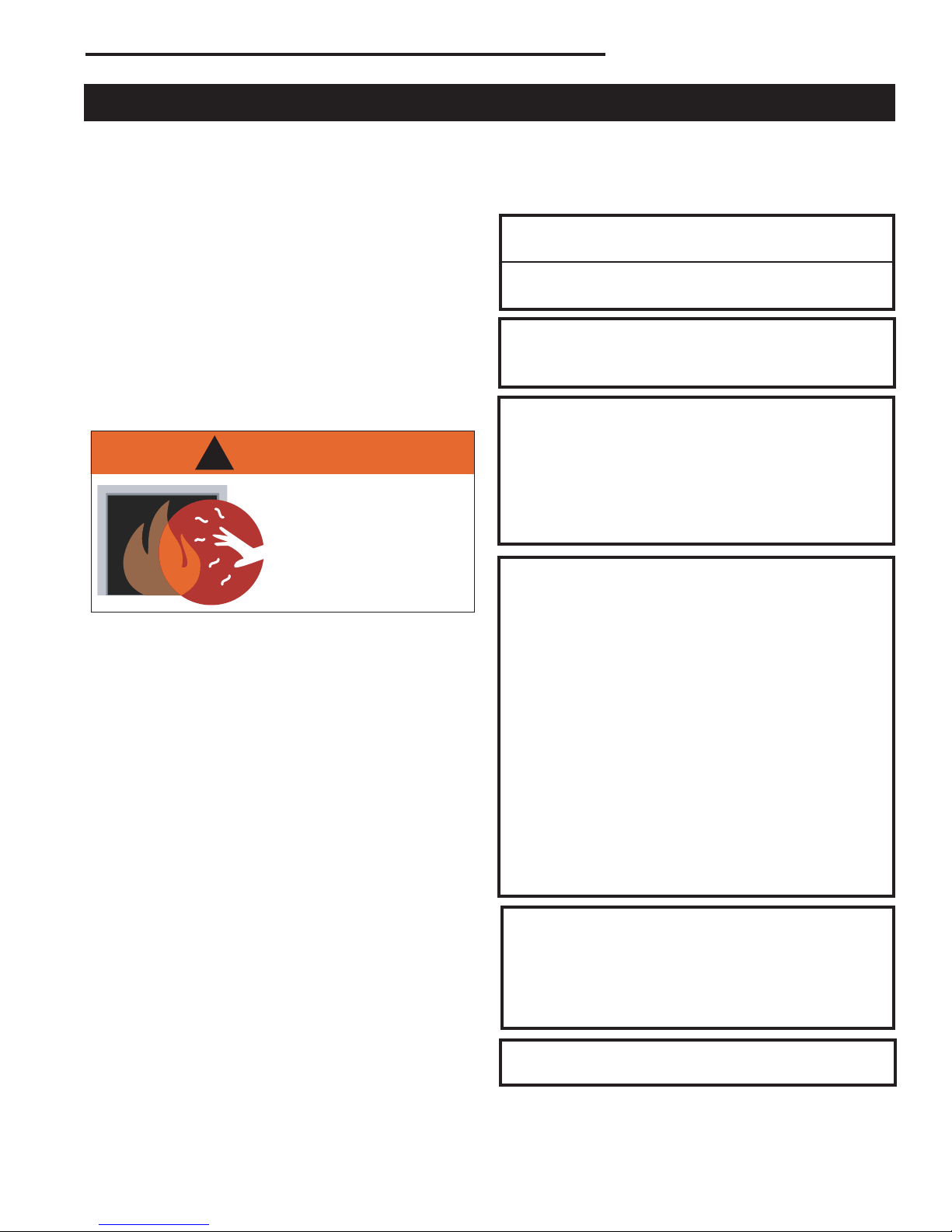
WARNING!
IF THE INFORMATION IN THIS
MANUAL IS NOT FOLLOWED
EXACTLY, A FIRE OR EXPLO
SION MAY RESULT CAUSING
PROPERTY DAMAGE, PERSONAL INJURY OR LOSS OF LIFE.
FOR YOUR SAFETY
Installation and service must
be performed by a qualified
installer, service agency or the
gas supplier.
WHAT TO DO IF YOU SMELL GAS:
• Do not try to light any appliance.
• Do not touch any electric switch; do not
use any phone in your building.
• Immediately call your gas supplier from
your neighbor’s phone. Follow the gas
suppliers instructions.
• If you cannot reach your gas supplier
call the fire department.
-
Direct Vent Zero Clearance
Gas Fireplace Heater
Models:
DV1000N/P, DV1200N/P, DV1400N/P
DO NOT STORE OR USE GASOLINE OR OTHER FLAMMABLE
VAPORS AND LIQUIDS IN THE
VICINITY OF THIS OR ANY OTHER APPLIANCE.
WARNING: Improper installation, adjustment, alteration, service or maintenance can cause injury or property
damage. Refer to this manual. For
assistance or additional information,
consult a qualified installer, service
agency or the gas supplier.
U.S. Patents: 5,669,374; 5,562,088; 6,138,667;
Can. Patent: 2,139,684
Homeowner’s Installation and
Operating Manual
INSTALLER: Leave this manual with the appliance.
CONSUMER: Retain this manual for future reference.
76657 5/08 Rev. 31

Temco DV1000/1200/1400 Series
Table of Contents
PLEASE READ THE INSTALLATION & OPERATING INSTRUCTIONS BEFORE USING APPLIANCE.
Thank you and congratulations on your purchase of a Temco Fireplace Products fireplace.
While we have written these instructions as accurately and thoroughly as possible, they may not cover every system,
variation or contingency. Also, questions of interpretation may arise. For more information, solutions to particular problems or clarifications, contact your local distributor or the manufacturer. See the unit rating plate for whom to contact.
IMPORTANT: Read all instructions and warnings carefully before starting installation. Failure to follow these
instructions may result in a possible fire hazard and will void the warranty.
Installation & Operating Instructions
General Information, Warnings, Cautions ............................................................. 3
Requirements for the Commonwealth of Massachusetts ...................................... 4
Fireplace Dimensions ............................................................................................
Locating Your Fireplace ......................................................................................... 6
Framing & Finishing ..............................................................................................
Clearance to Combustibles ................................................................................... 7
Combustible Sidewall Clearance .......................................................................... 7
Mantels ..................................................................................................................
Surround Material .................................................................................................. 7
Gas Specifications
Gas Inlet and Manifold Pressures ......................................................................... 8
Gas Line Installation .............................................................................................. 8
General Venting Information
General Venting .................................................................................................... 9
General Venting Information - Termination Location ...........................................
Termination Clearances .......................................................................................11
Sidewall (General)Venting Information ................................................................ 12
Flex Venting
Sidewall (Horizontal) Venting .............................................................................. 13
Flex Vent Offsets .................................................................................................
Flex Vent Through the Roof (Vertical) Applications ............................................. 15
VSK7 Vertical Flex Vent Kit Installation ............................................................... 15
TDV Series Direct Vent System Installation ........................................................
Sidewall (Horizontal) Venting, General ............................................................... 16
Through the Roof (Vertical) Venting ....................................................................
Elbows & Offsets - General ................................................................................ 17
Sidewall (Horizontal) Venting Information ........................................................... 17
Venting Components ...........................................................................................
Operating Instructions
Glass Door Removal Procedure .........................................................................
Glass Cleaning .................................................................................................... 24
Louvre Installation ............................................................................................... 24
Log Installation ....................................................................................................
Thermostatic Fan Kit - Optional........................................................................... 26
Electrical Services ...............................................................................................
Speed Control Switch .......................................................................................... 26
Millivolt System .................................................................................................... 26
Burner ON/OFF ...................................................................................................
Managing Heat Output ........................................................................................ 27
Fan Operation .....................................................................................................
Flame Characteristics .......................................................................................... 27
Lighting & Operating Instructions ........................................................................ 28
Troubleshooting ...................................................................................................
Maintenance
Unit Adjustment ...................................................................................................
Maintenance ........................................................................................................ 32
Replacement Parts ........................................................................................................ 35
Servicing ..............................................................................................................
Warranty .......................................................................................................................... 36
Installation and Startup Checklist ................................................................................. 37
Warranty Registration ................................................................................................... 39
................................................................................................. 8
......................................................................................................... 12
2
4
6
7
10
13
16
17
20
24
25
26
26
27
29
32
35
76657
Temco DV1000/1200/1400 Series
�
Installation & Operating Instructions
This gas appliance should be installed by a qualified
installer in accordance with local building codes and with
current CSA-B149.1 Installation codes for Gas Burning
Appliances and Equipment. For U.S.A Installations follow
local codes and/or the current National Fuel Gas Code.
ANSI Z223.1/NFPA 54.
FOR SAFE INSTALLATION AND OPERATION PLEASE
NOTE THE FOLLOWING:
1 . This fireplace gives off high temperatures and should be
located out of high traffic areas and away from furniture and
draperies.
2. Children and adults should be alerted to the hazards of the
high surface temperatures of this fireplace and should stay
away to avoid burns or ignition of clothing.
3. CAUTION: Due to high glass surface temperature chil-
dren should be carefully supervised when in the same
room as fireplace.
4. Under no circumstances should this fireplace be modified.
Parts removed for servicing should be replaced prior to
operating this fireplace again.
5. Installation and any repairs to this fireplace must be per
formed by a qualified installer, service agency or gas sup
plier. A professional service person should be contacted to
inspect this fireplace annually. Make it a practice to have
all of your gas fireplaces checked annually. More frequent
cleaning may be required due to excess lint and dust from
carpeting, bedding material, etc.
6. Control compartments, burners and air passages in this fireplace should be kept clean and free of dust and lint. Make
sure the gas valve and pilot light are turned off before you
attempt to clean this fireplace.
7. The venting system (chimney) of this fireplace should be
checked at least once a year and if needed your venting
system should be cleaned.
8. Keep the area around your fireplace clear of combustible
materials, gasoline and other flammable vapor and liquids.
This fireplace should not be used as a drying rack for clothing, nor should Christmas stocking or decorations be hung
in the area of it.
9. Under no circumstances should any solid fuels (wood, coal,
paper or cardboard etc.) be used in this fireplace.
10. For safe operation, the glass door must be closed.
11. Do not use this heater if any part has been under water.
Immediately call a qualified service technician to inspect the
heater and to replace any part of the control system and any
gas control which has been under water.
76657
12. Do not operate appliance unless completely installed as per
installation instructions.
13. This appliance may be used in a bedroom installation. Install
in accordance with local building codes and regulations.
14. Never use your fireplace as a cooking device.
DV1000 / DV1200 / DV1400
Certified To
ANSI Z21.88-2005 / CSA 2.33-2005 / UL 307B
Vented Gas Fireplace Heater
WARNING: Check with your electronics manufac
turer before installing a television or other electronic device above this fireplace.
This appliance may be installed in an aftermarket
permanently located, manufactured home or mobile home, where not prohibited by local codes.
This appliance is only for use with the type of gas
indi-cated on the rating plate. This appliance is
not convertible for use with other gases, unless a
certified kit is used.
IMPORTANT:
PLEASE READ THE FOLLOWING CAREFULLY
Remove any plastic from trim parts before turning the
fireplace ON.
It is normal for fireplaces fabricated of steel to give off
-
-
some expansion and/or contraction noises during the
start up or cool down cycle. Similar noises are found
with your furnace heat exchanger or car engine. It
is not unusual for your gas fireplace to give off some
odor the first time it is burned. This is due to the
manufacturing process.
Please ensure that your room is well ventilated
-open all windows.
It is recommended that you burn your fireplace for at
least four (4) hours the first time you use it. If the optional fan kit has been installed, place the fan switch
in the “OFF” position during this time.
The embers supplied with your fireplace are
made from a high grade rock wool and should be
handled carefully. Wash your hands immediately
after touching to avoid irritation. The embers
must be placed correctly in order to function
properly.
WARNING: When purging the gas line, the glass
front must be removed.
-
3

Temco DV1000/1200/1400 Series
Installation & Operating Instructions
Requirements for the Commonwealth of
Massachusetts
All gas fitting and installation of this heater shall only be
done by a licensed gas fitter or licensed plumber.
For all side wall horizontally vented gas fueled
equipment installed in every dwelling, building or
structure used in whole or in part for residential
purposes, including those owned or operated by the
Commonwealth and where the side wall exhaust vent
termination is less than seven (7) feet above finished
grade in the area of the venting, including but not limited
to decks and porches, the following requirements shall
be satisfied:
Installation of Carbon Monoxide Detectors
At the time of installation of the side wall horizontal
vented gas fueled equipment, the installing plumber
or gas fitter shall observe that a hard wired carbon
monoxide detector with an alarm is installed on each
additional level of the dwelling, building or structure
served by the side wall horizontally vented gas fueled
equipment. It shall be the responsibility of the property
owner to secure the services of qualified licensed
professionals for the installation of hard wired carbon
monoxide detectors.
In the event that the side wall horizontally vented gas
fueled equipment is installed in a crawl space or an
attic, the hard wired carbon monoxide detector with
alarm and battery back-up may be installed on the next
adjacent floor level.
In the event that the requirements of this subdivision
can not be met at the time of completion of installation,
the owner shall have a period of thirty (30) days
to comply with the above requirements; provided,
however, that during said thirty (30) day period, a
battery operated carbon monoxide detector with an
alarm shall be installed.
Approved Carbon Monoxide Detectors
Each carbon monoxide detector as required in
accordance with the above provisions shall comply with
NFPA 720 and ANSI/UL 2034 listed and IAS certified.
Signage
A metal or plastic identification plate shall be
permanently mounted to the exterior of the building at
a minimum height of eight (8) feet above grade directly
in line with the exhaust vent terminal for the horizontally
vented gas fueled heating appliance or equipment. The
sign shall read, in print size no less than one-half (1/2)
inch in size, “GAS VENT DIRECTLY BELOW, KEEP
CLEAR OF ALL OBSTRUCTIONS”.
4
Inspection
The state or local gas inspector of the side wall
horizontally vented gas fueled equipment shall not
approve the installation unless, upon inspection, the
inspector observes carbon monoxide detectors and
signage installed in accordance with the provisions of
248 CMR 5.08(2)(a)1 through 4.
Exemptions
The following equipment is exempt from 248 CMR
5.08(2)(a)1 through 4:
• The equipment listed in Chapter 10 entitled
“Equipment Not Required To Be Vented” in the most
current edition of NFPA 54 as adopted by the Board;
and
• Product Approved side wall horizontally vented gas
fueled equipment installed in a room or structure
separate from the dwelling, building or structure
used in whole or in part for residential purposes.
MANUFACTURER REQUIREMENTS
Gas Equipment Venting System Provided
When the manufacturer of Product Approved side
wall horizontally vented gas equipment provides a
venting system design or venting system components
with the equipment, the instructions provided by the
manufacturer for installation of the equipment and the
venting system shall include:
• Detailed instructions for the installation of the venting
system design or the venting system components;
and
• A complete parts list for the venting system design or
venting system.
Gas Equipment Venting System NOT Provided
When the manufacturer of a Product Approved side
wall horizontally vented gas fueled equipment does
not provide the parts for venting the flue gases, but
identifies “special venting systems”, the following
requirements shall be satisfied by the manufacturer:
• The referenced “special venting system” instructions
shall be included with the appliance or equipment
installation instructions; and
• The “special venting systems” shall be Product
Approved by the Board, and the instructions for
that system shall include a parts list and detailed
installation instructions.
A copy of all installation instructions for all Product
Approved side wall horizontally vented gas fueled
equipment, all venting instructions, all parts lists
for venting instructions, and/or all venting design
instructions shall remain with the appliance or
equipment at the completion of the installation.
76657
S - Rough Opening Width
Rough
Opening
Height
Rough
Opening
Depth
A
C
L
4" (102 mm) Dia.
7" (178 mm) Dia.
1/2" (13 mm)
Q
Q
P
T
I
J
R
B
K
L
M
N
C
H
E
F
G
K
L
M
N
O
D
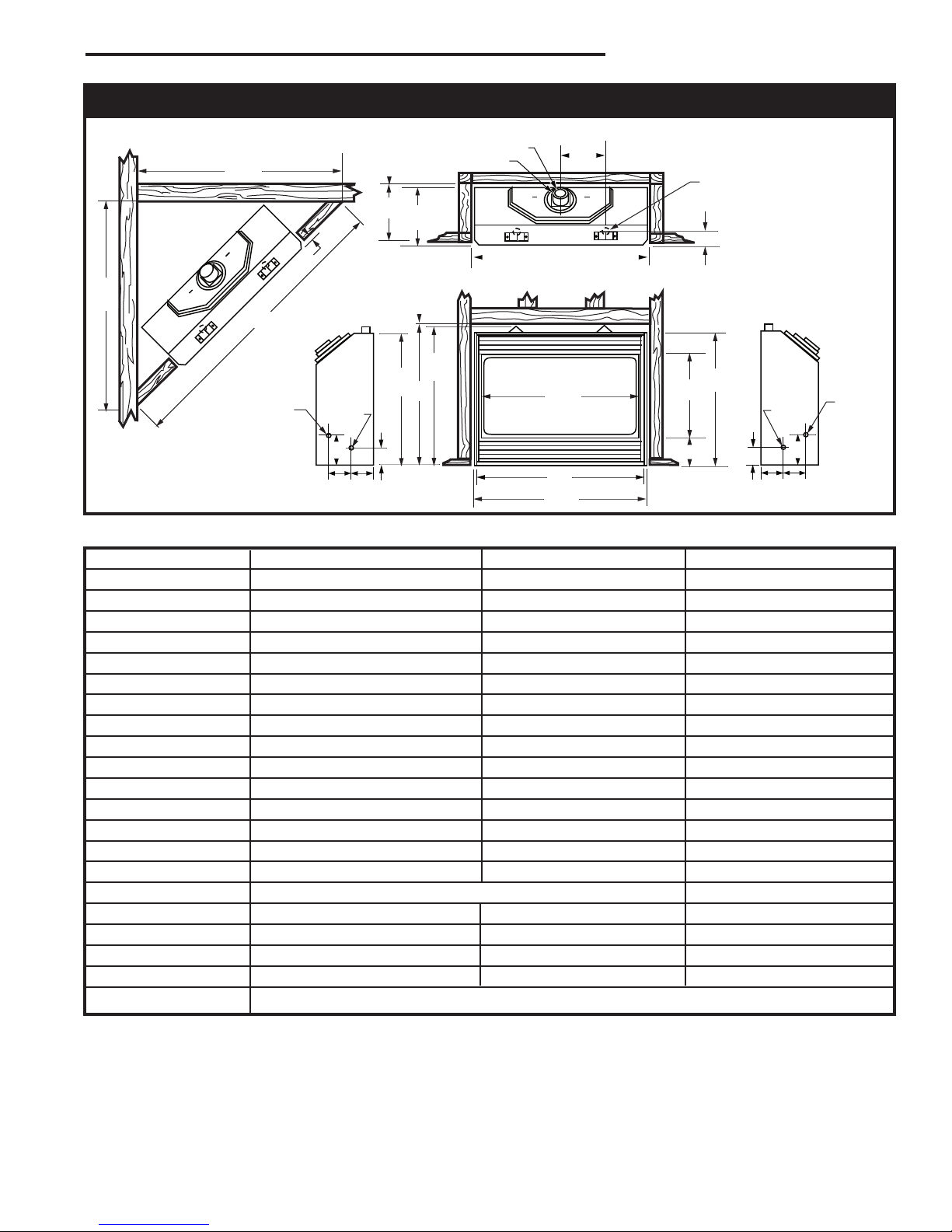
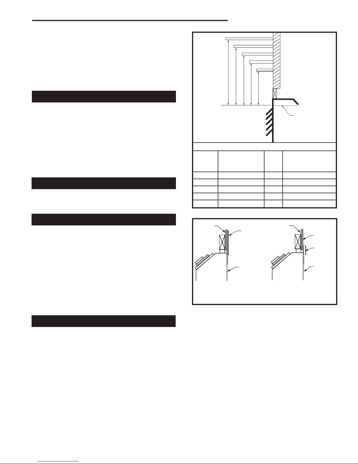
Fireplace Dimensions
Temco DV1000/1200/1400 Series
Bottom Gas Line Access
Gas Line
Access
NOTE: Flex pipe dimaeters are
4” for inner pipe and 7” for outer
pipe.
Fig. 1 Fireplace specifications and framing dimensions.
J Box
Access
J Box
Access
Gas
Line
Access
Ref. DV1000 DV1200 DV1400
A 34
B 28
C 31
D 29
E 16
F 5
G 27
H 32
I 13
J 13
K 1
L 5
M 3
N 3
O 3” (76mm) 3” (76mm) 3” (76mm)
P 63
Q 44
R 30
S 34
T Refer to Figure 3 or 4 for Rough Opening Depth
¹⁄₄” (870mm) 35¹³⁄₁₆” (190mm) 41³⁄₄” (1061mm)
³⁄₈” (721mm) 33” (838mm) 33” (838mm0
¹⁄₈” (791mm) 32⁹⁄₁₆” (827mm) 38³⁄₄” (984mm)
⁷⁄₈” (759mm) 34¹⁄₂” (876mm) 34¹⁄₂” (876mm)
³⁄₄” (426mm) 21³⁄₈” (543mm) 21³⁄₈” (543mm0
³⁄₄” (146mm) 6¹⁄₄” (159mm) 6¹⁄₄” (159mm)
¹⁄₂” (699mm) 32” (813mm) 32” (813mm)
³⁄₄” (832mm) 34¹⁄₄” (870mm) 40¹⁄₄” (1022mm)
¹⁄₈” (333mm) 14¹⁄₄” (362mm) 14¹⁄₄” (362mm)
³⁄₈” (340mm) 13³⁄₈” (340mm) 13³⁄₈” (340mm)
⁵⁄₈” (41mm) 1⁵⁄₈” (41mm) 1⁵⁄₈” (41mm)
¹⁄₈” (130mm) 5⁵⁄₈” (143mm) 5⁵⁄₈” (143mm)
³⁄₄” (95mm) 4¹⁄₂” (114mm) 4¹⁄₂” (114mm)
³⁄₄” (95mm) 4¹⁄₂” (114mm) 4¹⁄₂” (114mm)
Framing Dimensions
⁵⁄₃₂” (1604mm) 64²⁹⁄₃₂” (1633mm) 71³⁄₁₆” (1808mm)
¹¹⁄₁₆” (1135mm) 45⁷⁄₈” (1165mm) 50⁵⁄₁₆” (1295mm)
¹⁄₈” (765mm) 34³⁄₄” (883mm) 34³⁄₄” (883mm)
¹⁄₂” (876mm) 36” (914mm) 42” (1067mm)
76657
5
Temco DV1000/1200/1400 Series
X
A
B
C
10³⁄₄"
(273mm)
Min.
D
Y
E
A
B
C
D
F
Y
B
X
X
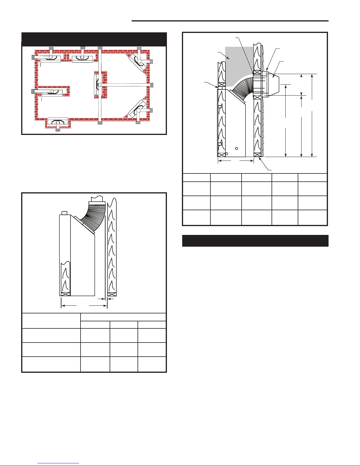
Locating Your Fireplace
LU584-1
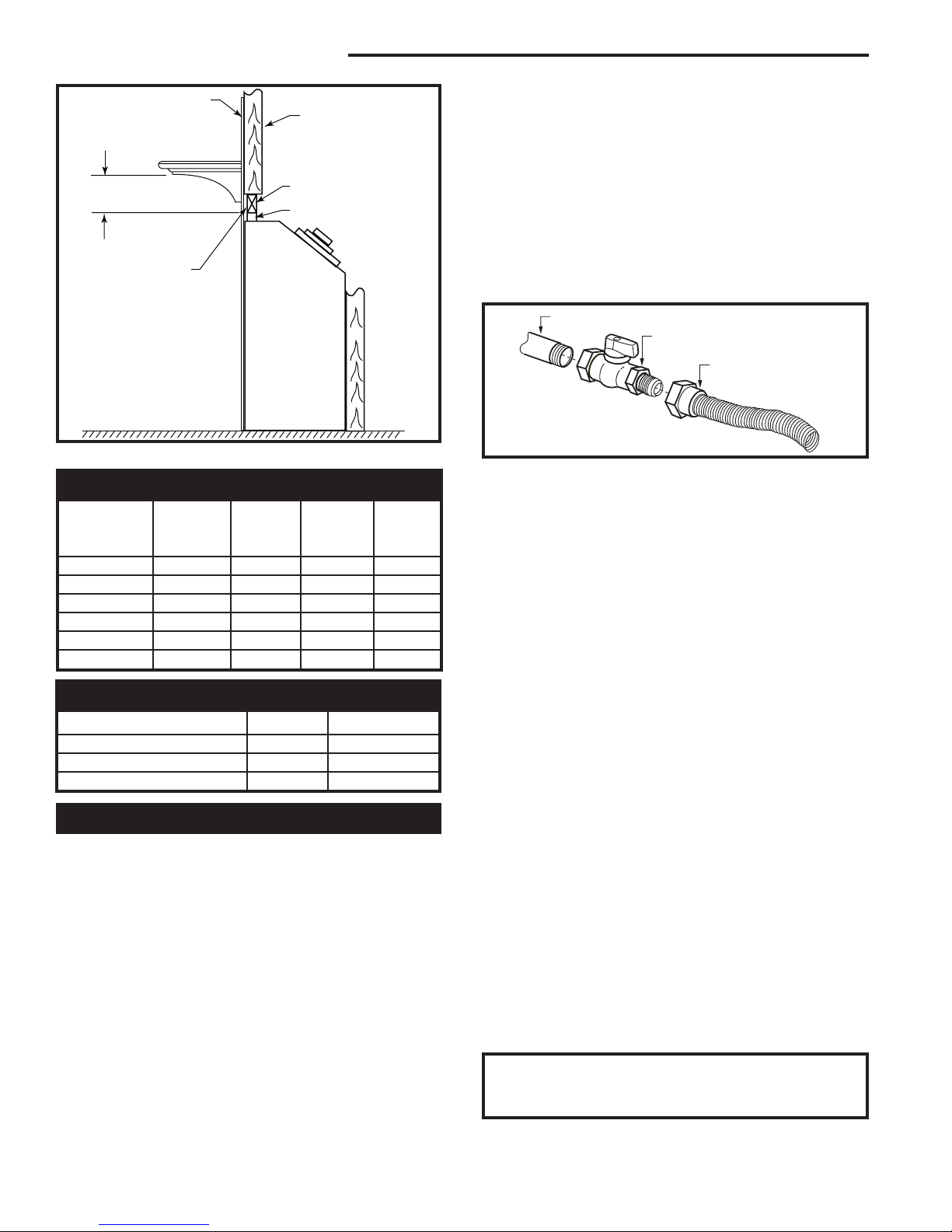
Fig. 2 Locate gas fireplace.
A) Flat on wall B) Cross Corner C) As an Island
D) As a room divider E) Flat on wall corner F) Exterior wall
Island installation is possible as long as the horizontal portion of the
vent system does not exceed maximum recommended horizontal run
as outlined in the venting chart on Page 10. When you install your
fireplace as in position ‘B’, ‘D’ or ‘E’, (Fig. 2) a minimum of 1” (25mm)
clearance must be maintained from the perpendicular wall and the
front of the appliance.
Firestop/Wall Sleeve
VEF (Vinyl Siding)
Combustible
Construction
Allowed
Standoff
T176
or BEF (Brick)
Extension flange
Vent Terminal
2 x 4 or 2 x 6 Framing
Model A B C D
DV1000 15³⁄₈” Min. 30¹⁄₈” 25³⁄₈” 36¹⁄₈”
(391mm) (765mm) (645mm) (918mm)
DV1200 16¹⁄₂” Min. 34³⁄₄” 30” 40³⁄₄”
(419mm) (883mm) (762mm) (1035mm)
DV1400 16¹⁄₂” Min. 40³⁄₄” 36” 46³⁄₄”
(419mm) (1035mm) (914mm) (1188mm)
Fig. 4 Minimum framing dimensions with horizontal venting.
1” (25 mm)
Minimum Air Space
T175
Clearance to Combustible Materials
Vent “X”
System Used DV1000 DV1200 DV1400
TEMCO 4/7 Flex 17¹⁄₂” 18¹⁄₂” 19¹⁄₂”
(445 mm) (470 mm) (495 mm)
TEMCO 4/7 Rigid 18¹⁄₂” 19¹⁄₂” 19¹⁄₂”
(470 mm) (495 mm) (495 mm)
Duravent 4/6-5/8 GS 17¹⁄₂” 18¹⁄₂” 18¹⁄₂”
(445 mm) (470 mm) (470 mm)
Fig. 3 Minimum framing depths with vertical takeoff.
6
Framing and Finishing
1. Choose a fireplace location and frame in accordance
with the fireplace dimensions specified on Page 3 of
this manual. When using a surround, the fireplace
must be flush to the wall. Also, allowances must
be made for drywall, tile or any other facing used
around the unit.
2. When the appliance is installed directly on carpeting,
tile or other combustible material other than wood
flooring, the appliance shall be installed on a metal
or wood platform.
3. Pull out the nail tabs which are located on each side
of the fireplace. Move the fireplace into position and
secure to the floor with screws or nails through the
holes provided in the bottom flanges of the side cas
ing. After checking unit for squareness, secure top of
fireplace to the framing with screws or nails using the
nailing tabs provided.
4. Cold climate installation recommendation: when
installing this fireplace against a non-insulated exterior wall or chase, it is recommended that the outer
walls be insulated to conform to applicable insulation
codes. Drywall should be installed around the unit to
prevent insulation from contacting the body.
Note: Never let vapor barrier contact the outer
case of this fireplace or venting.
-
76657
5. Drywall can be extended flush on the bottom, top
A B C D E
V
W
X
Y
Z
Fireplace
and to the outermost part of the sides of the fireplace.
6. Noncombustible materials such as brick and tile
can be extended across the face of the fireplace. If
brass trim kit is going to be installed, brick and tile
will have to be installed flush with the front of this
appliance.
Clearance to Combustibles
Top of unit to ceiling* ................................36” (914 mm)
Front of unit to combustibles ....................36” (914 mm)
Appliance
Top (from standoffs) .................................0” (0mm)
Bottom ......................................................0” (0mm)
Side (from standoffs) .................................0” (0mm)
Back (from standoffs) ................................0” (0mm)
Top of Elbow ...........................................2” (51mm)
* Ceiling height is the minimum height of the room ceiling in front of
the fireplace measured from the top front edge of the fireplace.
Combustible Sidewall Clearance
The perpendicular combustible sidewall or mantel support leg (surround) clearance is 1³⁄₄” (45mm) from the
edge of the recessed door opening.
Mantels
The height that a combustible mantel is fitted above the
fireplace is dependent on the depth of the mantel.
For the correct mounting height and widths, refer to
Figure 5.
Noncombustible mantels and legs may be installed at
any height and width around the appliance. When using
paint or lacquer, it must be heat resistant to prevent
discoloration.
WARNING: Combustible objects must not be placed
on a noncombustible mantel unless the noncombustible
mantel meets the minimum height and width requirements for a combustible mantel.
Temco DV1000/1200/1400 Series
Top of Louvre
Opening
T177
Mantel Chart
Mantel Shelf Mantel from Top
Ref. or Breast Plate Ref. of Louvre Opening
Depth
V 10” (254 mm) A 14” (356 mm)
W 8” (203 mm) B 12” (305 mm)
X 6” (152 mm) C 10” (254 mm)
Y 4” (101 mm) D 8” (203 mm)
Z 2” (51 mm) E 6” (152 mm)
Fig. 5 combustible mantel minimum installation.
Drywall
Tile, Marble, etc.
Fireplace
Front
Noncombustible Facing
Material Overlap of Front Face
Fig. 6 Surround material options.
Drywall
Flush Face Installation
(Recommended when
installing optional trim
surround kits)
Tile,
Marble,
etc.
Optional
Surround
Kits
Fireplace
Front
T178
Surround Material
When using materials around the face of the fireplace,
these materials must be suitable to withstand the temperatures which they will encounter. Also these materials must not extend out in front of the face of the unit, in
effect recessing the unit.
If the material used for surround is not flush with the
face of the unit, then the optional surround kits will not
fit properly.
It is recommended that any material used to surround
the face of the fireplace be noncombustible (i.e. ceramic tile, brick, natural stone, etc.). Combustible materials
such as drywall, are permissible.
76657
Materials such as cultured marble or other synthetic
materials are not recommended as they may discolor,
warp or create odor as a result of exposure to the temperatures of the front of the fireplace.
7
Temco DV1000/1200/1400 Series
Combustible Material
2 x 4 Stud
Minimum Height from
Top Opening to Mantel
Combustible Material
Above Standoff
Optional Hearth
Fig. 7 Gas fireplace installation.
2 x 4 Header
Standoff
T179
Gas Specifications
Max. Min.
Gas Input Input
Model Fuel Control BTU/h BTU/h
DV1000N Natural Hi/Lo 18,500 12,500
DV1000P Propane Hi/Lo 18,500 12,500
DV1200N Natural Hi/Lo 20,000 13,000
DV1200P Propane Hi/Lo 20,000 13,000
DV1400N Natural Hi/Lo 22,000 15,000
DV1400P Propane Hi/Lo 22,000 15,000
Gas Inlet and Manifold Pressures
Natural LP (Propane)
Minimum Inlet Pressure 4.5” w.c. 10.8” w.c.
Maximum Inlet Pressure 14.0” w.c. 14.0” w.c.
Manifold Pressure 3.5” w.c. 10.0” w.c.
Gas Line Installation
This gas appliance should be installed by a qualified installer in accordance with local building codes and with
current CSA-B149.1 installation codes for Gas Burning
Appliances and Equipment in Canada and the National
Fuel Gas Code ANSI Z223.1/NFPA 54 in the U.S.A.*
1. The gas pipeline can be brought in through the bot
tom or the right or the left side of the appliance. A
hole is provided at all locations to allow for the gas
pipe installation and testing of any gas connection.
2. The gas control inlet is 3/8” NPT. Typical installation
layout for rigid pipe is shown on Page 8.
NOTE: All models are equipped with a flex tube
with a shut off valve having a 1/2” NPT inlet. The
flex line with shut off is shipped in the control valve compartment. Using two wrenches,
-
tighten the flexible tube at the shut off valve and
at the gas control.
3. When using a flex connector,* use only approved
fittings. When a union is installed, provide easy
access in it’s placement for servicing. Refer to gas
specification for pressure details and ratings.
4. When a vertical section of gas pipe is required for
the installation, a condensation trap is needed. In
Canada see CSA - B149.1 for code details. See the
National Fuel Gas Code ANSI Z223.1/NFPA 54 in
the USA.
1/2” Gas Supply
1/2” NPT x 1/2” Flare Shut-off Valve
1/2” Flex Line
(from valve)
FP297a
Fig. 8 Typical gas supply installation.
5. For natural gas, a minimum of 3/8” iron pipe with
a gas supply pressure of 4.5” w.c. (from the gas
meter). Consult with local gas utility and ANSI223.1/
NFPA 54 if any questions arise concerning pipe
sizes.
6. Turn the gas supply to ‘ON’ and check for leaks. DO
NOT USE OPEN FLAME FOR THIS PURPOSE.
Use an approved leak testing solution.
7. The appliance and its appliance main gas valve
must be disconnected from the gas supply piping
system during any pressure testing of that system at
test pressures in excess of 1/2psig (3.5 KPa).
8. The appliance must be isolated from the gas supply piping system by closing its equipment shut off
valve during any pressure testing of the gas supply
piping system at test pressures equal to or less than
1/2psig (3.5KPa).
NOTE: The gas line connection may be made of 3/8”
minimum rigid pipe, 3/8” minimum copper pipe or an approved flex connector. Since some municipalities have
additional local codes, it is always best to consult your
local authorities and the current CSA-B149.1 installation code in Canada or National Fuel Gas Code ANSI
Z223.1/NFPA 54 in the U.S.A.
*Adhere to the following installation requirements in the State of Massachusetts:
• The installer must be a licensed plumber or gas fitter.
• Flex connectors must be Massachusetts approved, cannot
exceed 36” (914 mm) in length, must be a minimum 1/2” dia., and
may not penetrate a wall.
IMPORTANT: Always check for gas leaks with a
soap and water solution. Do not use open flame
for leak testing.
8
76657

General Venting
Temco DV1000/1200/1400 Series
When locating the vent termination, the minimum vent
clearances must be observed. (Page 10, Fig. 9)
NOTE: Local codes may require different clearances.
It is recommended that the termination not be located
within 24” (305mm) of garden sheds, fences, decks,
utility buildings or other obstructions.
Do not locate termination cap where excessive snow or
ice build up may occur. Be sure to check vent termination area after snow falls and clear to prevent accidental
blockage of venting system. When using snow blowers,
make sure snow is not directed towards vent termination area.
This appliance has a “special vent system”. Check
with local codes or in the absence of same, with CSA
B149.1 installation codes in Canada, or the current
National Fuel Gas Code ANSI Z223.1/NFPA 54 in the
USA, regarding special vent termination clearances.
These fireplaces are certified for use with four types of
venting systems
1. Temco 4” x 7” dia. flex vent.
2. Temco TDV series 4” x 7” dia. rigid vent.
3. Simpson Dura-Vent GS series 4” x 6⁵⁄₈” dia. vent.
4. Security Secure Vent series 4” x 6⁵⁄₈” dia. vent.
Review general venting information in this manual, and
information packed with the venting prior to starting the
installation of the fireplace.
• Termination shall not be recessed into a wall or siding.
• Horizontal sections must maintain a minimum 1/4”
rise per linear foot of horizontal run.
• Combustible clearances from any horizontal vent
pipe area must be 2” (51 mm) from top of vent, and
1” (25 mm) from sides and bottom.
• Clearance to combustibles from vertical pipe surface
is 1” (25 mm).
76657
9
Temco DV1000/1200/1400 Series
V
V
V
V
V
V
V
X
X
X
D
E
B
B
B
C
B
M
B
A
J
K
F
L
VENT TERMINATION AIR SUPPLY INLET
AREA WHERE TERMINAL IS NOT PERMITTED
H
I
Fixed
Closed
Fixed
Closed
Operabl
e
Operable
Fixed
Closed
V
B
INSIDE
CORNER DETAIL
V
A
G
V
N
N
V
V
G
G
A
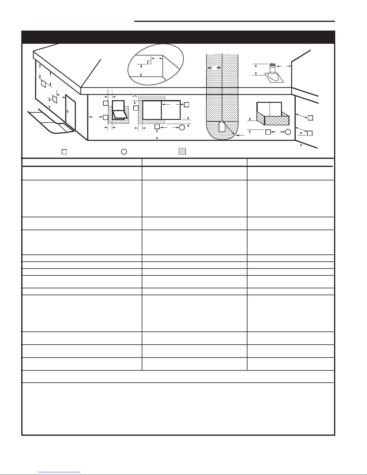
General Venting Information - Termination Location
Canadian Installations1 US Installations
A = Clearance above grade, veranda, porch, 12” (30 cm) 12” (30 cm)
deck, or balcony
B = Clearance to window or door that may be 6” (15 cm) for appliances 6” (15 cm) for appliances
opened < 10,000Btuh (3kW), 12” (30 cm) < 10,000 Btuh (3kW), 9”
for appliances > 10,000 Btuh (3kW) and (23 cm) for appliances > 10,000
< 100,000 Btuh (30kW), 36” (91 cm) Btuh (3kW) and < 50,000 Btuh
for appliances > 100,000 Btuh (30kW) (15kW), 12” (30 cm) for
appliances > 50,000 Btuh (15kW)
C = Clearance to permanently closed window 12” (305 mm) recommended to 12” (305 mm) recommended to
prevent window condensation prevent window condensation
D = Vertical clearance to ventilated soffit located
above the terminal within a horizontal 18” (458 mm) 18” (458 mm)
distance of 2 feet (610mm) from the center
line of the terminal
E = Clearance to unventilated soffit 12” (305 mm) 12” (305 mm)
F = Clearance to outside corner see next page see next page
G = Clearance to inside corner (see next page) see next page see next page
H = Clearance to each inside of center line 3’ (91 cm) within a height of 15’ 3’ (91 cm) within a height of 15’
extended above meter/regulator assembly above the meter/regulator assembly above the meter/regulator assy
I = Clearance to service regulator vent outlet 3’ (91 cm) 3’ (91 cm)
J = Clearance to nonmechanical air supply inlet 6” (15 cm) for appliances < 10,000 6” (15 cm) for appliances
to building or the combustion air inlet to any Btuh (3kW), 12” (30 cm) for < 10,000 Btuh (3kW), 9”
other appliances appliances > 10,000 Btuh (3kW) and < (23 cm) for appliances > 10,000
100,000 Btuh (30kW), 36” (91 cm) Btuh (3kW) and < 50,000 Btuh
for appliances > 100,000 Btuh (30kW) (15kW), 12” (30 cm) for
appliances > 50,000 Btuh (15kW)
K = Clearance to a mechanical air supply inlet 6’ (1.83 m) 3’ (91 cm) above if within 10’
(3 m) horizontally
L = Clearance above paved sidewalk or paved 7’ (2.13 m)† 7’ (2.13 m)†
driveway located on public property
M = Clearance under veranda, porch, deck or 12” (30 cm)‡ 12” (30 cm)‡
balcony
N = Clearance above a roof shall extend a minimum of 24” (610 mm) above the highest point when it passes through the roof
surface, and any other obstruction within a horizontal distance of 18” (450 mm).
1 In accordance with the current CSA-B149 Installation Codes
2 In accordance with the current ANSI Z223.1/NFPA 54 National Fuel Gas Codes
† A vent shall not terminate directly above a sidewalk or paved driveway which is located between two single family dwellings and serves both dwell ings
‡ only permitted if veranda, porch, deck or balcony is fully open on a minimum 2 sides beneath the floor:
NOTE: 1. Local codes or regulations may require different clearances.
2. The special venting system used on Direct Vent Fireplaces are certified as part of the appliance, with clearances tested and approved by the
listing agency.
3. CFM Corporation assumes no responsibility for the improper performance of the appliance when the venting system does not
meet these requirements.
Fig. 9 Vent termination clearances.
10
2
76657
2" (51mm)
1" (25mm)
1"
(25mm)
0
5'
46"
(1168mm)
33¹⁄₂"
(851mm)
10'
15'
25'
30'
32'
0 3
'
5' 10'
15'
Outside Corner
Inside Corner
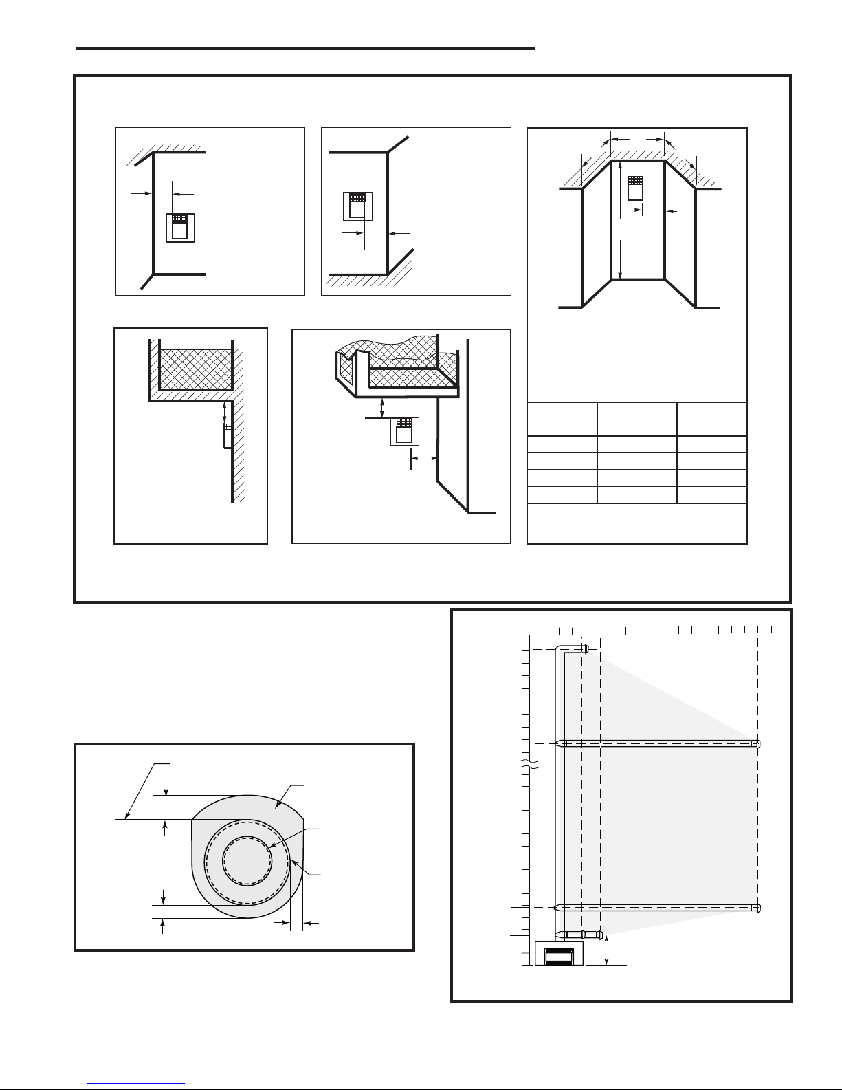
Termination Clearances
Termination clearances for buildings with combustible and noncombustible exteriors.
G =
Combustible
6" (152 mm)
Noncombustible
2" (51 mm)
F =
Combustible
6" (152 mm)
Noncombustible
2" (51 mm)
G
Balcony with no side wall
M =
Combustible &
Noncombustible
12" (305 mm)
M
Balcony with perpendicular side wall
M = 24" (610 mm)
P = 20” (508 mm)
M
F
Alcove Applications*
C
D
C
E
V
V
Combustible &
Noncombustible
V
V
V
E = Min. 6” (152 mm) for
non-vinyl sidewalls
Min. 12” (305 mm) for
vinyl sidewalls
O = 8’ (2.4 m) Min.
O
P
*NOTE: Termination in an alcove space (spaces open only on one side and with an overhang) is permitted with the dimensions
specified for vinyl or non-vinyl siding and soffits. 1. There must be a 3’ (914 mm) minimum between termination caps. 2. All
mechanical air intakes within 10’ (1 m) of a termination cap must be a minimum of 3’ (914 mm) below the termination cap. 3. All
gravity air intakes within 3’ (914 mm) of a termination cap must be a minimum of 1’ (305 mm) below the termination cap.
Fig. 10 Termination clearances.
NOTE: Use only venting systems and components
as certified with the appliance. Use of uncertified vent
systems or components will void the warranty and may
compromise the operation of the fireplace, its systems,
and components as certified with the appliance.
Top of Vent
Combustibles
NOT Allowed in
Shaded Area
4” Dia. Flue
Temco DV1000/1200/1400 Series
No.
of Caps D
1 3’ (914 mm) 2 x D
2 6’ (1.8 m) 1 x D
3 9’ (2.7 m) 2/3 x D
4 12’ (3.7 m) 1/2 x D
D
= # of Termination caps x 3
Min.
C
= (2 / # termination caps) x D
Max.
C
Min.
Max.
Actual
Actual
Actual
Actual
Actual
584-15
Fig. 11 Vent clearances.
76657
7” Dia. Intake
Vent
T181
* Min. Refer to Chart on Page 6
Fig. 12 Venting graph.
A vent guard should be
used whenever the termination is lower than the speci-
*
fied minimum or as per local
codes
T180
11
Temco DV1000/1200/1400 Series
MILL-PAC
MILL-PAC
H
12
x
33"
(838mm)
Minimu
m
53" (1346mm)
Maximum
28' (8.5m)
2' (610mm)
Minimum
B
12" (305mm)
Minimum
A
10' (3m)
Minimum
If length "B" is increased,
length "A" must be decrease
d
by a corresponding amount
10³⁄₄”
(273 mm)
Vent Opening for Combustible Wall
9³⁄₄”
(248 mm)
5⁷⁄₈”
(149 mm)
4⁷⁄₈”
(124 mm)
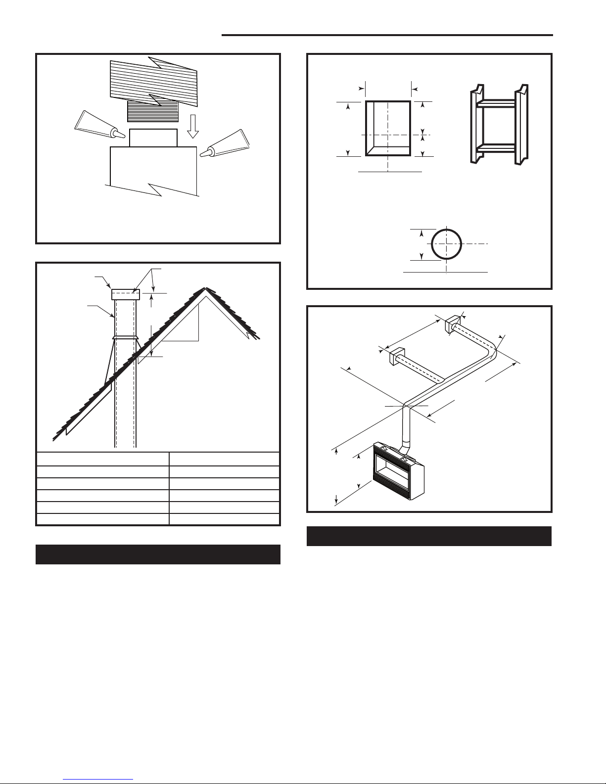
NOTE: Apply sealant “Mill-Pac” to inner pipe and “Mill-Pac” or high
temperature silicone sealant to outer pipe. Sealant should be applied at every joint in the vent system including at the fireplace and
at the vent terminal.
T182
Fig. 13 Apply sealant at every joint in vent system.
Vent Cap
Gas Vent
Lowest Discharge Opening
Roof Pitch X/12
H (Min.) - Minimum height
from roof to lowest discharge
opening
T183
Roof Pitch H (Min.)
Flat to 6/12 12” (305 mm)
6/12 to 7/12 15” (381 mm)
Over 7/12 to 8/12 18” (457 mm)
Over 8/12 to 16/12 24” (610 mm)
Over 16/12 to 21/12 36” (914 mm)
Fig. 14 Vertical termination location.
Fireplace Hearth
Opening for Noncombustible Wall
8” Dia.
(203 mm)
Min.
Fireplace Hearth
Fig. 15 Locate vent opening on wall.
A vent guard should be used
whenever the termination is
lower than the specified minimum or as per local codes.
Fig. 16 Horizontal vent run.
Flex Venting
Framing Detail
Rnd.
VO584-100
T184
Sidewall (General) Venting Information
Figures 15 and 16 show examples of horizontal termination arrangements using two 90° elbows (Rigid Vent).
NOTE:
1. A maximum of two 90° elbows are permitted.
2. A minimum of 10’ (3 m) vertical from base of unit is
required if two 90° elbows are used.
3. Minimum distance between elbows is 2’ (610 mm).
4. Determine the permitted range of horizontal termination arrangement by using chart above and
deducting 3’ (914 mm) from the maximum horizontal
distance for the second 90° elbow.
12
• Flex vent shall use the spacer springs as included
every foot to ensure proper vent operation.
• The 4” x 7” flex system may be used for all sidewall
applications and vertical venting up to 35’ (10.7 m).
• Flex shall be properly supported so there are no
sags in the system. Supports must be used at least
every 24” (610 mm) on horizontal section and every
36” (914 mm) on vertical. Wire or metal stripping
may be used to support the venting.
• For 4” x 7” flex, the 7” flex has an outside diameter
of 7¹⁄₂” (191 mm) and if installed in a chase the inside diameter of the chase should be 9¹⁄₂” (241 mm)
minimum.
76657
 Loading...