

Temco 36CDVXRRN, 36CDVXTRN Installation Instructions And Homeowner's Manual
INSTALLER/CONSUMER
D
E
S
I
G
N
�
C
E
R
T
I
F
I
E
D
CER TIF IED
SAFETY INFORMATION
PLEASE READ THIS MANUAL
BEFORE INSTALLING AND
USING APPLIANCE
WARNING!
IF THE INFORMATION IN THIS
MANUAL IS NOT FOLLOWED
EXACTLY, A FIRE OR EXPLOSION MAY RESULT CAUSING
PROPERTY DAMAGE, PERSONAL INJURY OR LOSS OF
LIFE.
FOR YOUR SAFETY
Installation and service must
be performed by a qualified
installer, service agency or
the gas supplier.
WHAT TO DO IF YOU SMELL GAS:
• Do not try to light any appliance.
• Do not touch any electric switch;
do not use any phone in your
building.
• Immediately call your gas
supplier from your neighbor’s
phone. Follow the gas suppliers
instructions.
• If you cannot reach your gas
supplier call the fire department.
Builder Direct Vent
Models:
36CDVXRRN (Rear Vent)
36CDVXTRN (Top Vent)
Installation Instructions and
DO NOT STORE OR USE
GASOLINE OR OTHER
FLAMMABLE VAPORS AND
LIQUIDS IN THE VICINITY OF
THIS OR ANY OTHER
APPLIANCE.
Homeowner’s Manual
INSTALLER: Leave this manual with the appliance.
CONSUMER: Retain this manual for future reference.
20012253 4/07 Rev. 1

CDVX Series Direct Vent Gas Fireplace
Table of Contents
PLEASE READ THE INSTALLATION & OPERATING INSTRUCTIONS
BEFORE USING APPLIANCE.
Thank you and congratulations on your purchase of a CFM Corporation fireplace.
IMPORTANT: Read all instructions and warnings carefully before starting installation.
Failure to follow these instructions fully may result in a possible fire hazard and will void the warranty.
Installation & Operating Instructions
Important Curing/Burning Instructions .................................................................................................3
Fireplace Dimensions ..........................................................................................................................4
Locating Your Fireplace .......................................................................................................................6
Clearance to Combustibles .................................................................................................................
Mantels .............................................................................................................................................6
Hearth .............................................................................................................................................
Framing and Finishing .........................................................................................................................7
Hood Installation ..................................................................................................................................7
Final Finishing .....................................................................................................................................
Gas Specifications ...............................................................................................................................8
Gas Inlet and Manifold Pressures .......................................................................................................
High Elevations ....................................................................................................................................8
Gas Line Installation ............................................................................................................................8
Remote ON/OFF Switch ......................................................................................................................
120V Electrical Hook Up ......................................................................................................................
General Venting Information
General Venting ...................................................................................................................................9
General Venting Information-Termination Location ...........................................................................10
General Information Assembling Vent Pipes .....................................................................................11
36CDVXR Venting - How to Use the Vent Graph ..............................................................................
Rear Wall Venting Applications & Installation (Exterior outside wall 7” - 20” from rear of unit) ..........12
Rear Wall Vent Installation - Flex Vent PIpe ......................................................................................
Rear Wall Vent Application (Exterior outside wall 13” - 20” from rear of unit) ....................................15
Rear Wall Vent Application (Exterior outside wall 20” - 32” from rear of unit) ....................................
Vertical Sidewall Applications & Installation .......................................................................................16
Below Grade Installation ....................................................................................................................18
Vertical Through-the-Roof Applications & Installation ........................................................................
36CDVXT Vertical Venting - How to Use the Vent Graph ..................................................................21
36CDVXT Top Vent Baffle .................................................................................................................
Vertical Sidewall Applications & Installation .......................................................................................22
Below Grade Installation ....................................................................................................................24
Vertical Through-the-Roof Applications & Installation ........................................................................
Venting Components .........................................................................................................................27
Operating Instructions
Glass Information ..............................................................................................................................28
Louvre Removal ................................................................................................................................
Window Frame Assembly Removal ...................................................................................................28
Glass Cleaning ..................................................................................................................................28
Logs ...........................................................................................................................................
Ember Material and Lava Rock Placement .......................................................................................29
Flame & Temperature Adjustment .....................................................................................................
Flame Characteristics ........................................................................................................................29
Lighting and Operating Instructions ...................................................................................................30
Troubleshooting .................................................................................................................................
Fuel Conversion Instructions .............................................................................................................33
Maintenance
Cleaning the Standing Pilot Control System ......................................................................................35
Replacement Parts ...................................................................................................................................36
Optional Accessories ................................................................................................................................38
Warranty .......................................................................................................................................................39
Energuide ....................................................................................................................................................40
6
7
7
8
8
9
12
14
15
19
21
25
28
29
29
32
2
20012253
CDVX Series Direct Vent Gas Fireplace
Installation & Operating Instructions
This gas appliance should be installed by a qualified
installer, preferably NFI or WETT (Canada) certified,
in accordance with local building codes and with
current CSA-B149.1 Installation codes for Gas Burning
Appliances and Equipment. For USA Installations follow
local codes and/or the current National Fuel Gas Code.
ANSI Z223.1/NFPA 54.
In the Commonwealth of Massachusetts, all gas fitting
and installation of this heater shall only be done by a
licensed gas fitter or licensed plumber.
FOR SAFE INSTALLATION AND OPERATION PLEASE
NOTE THE FOLLOWING:
1. This fireplace gives off high temperatures and should
be located out of high traffic areas and away from
furniture and draperies.
2. Children and adults should be alerted to the hazards
of high surface temperatures of this fireplace and
should stay away to avoid burns or ignition of clothing.
3. CAUTION: Due to high glass surface temperature
children should be carefully supervised when in
the same room as fireplace.
4. Under no circumstances should this fireplace be
modified. Parts removed for servicing should be
replaced prior to operating this fireplace again.
5. Installation and any repairs to this fireplace must be
performed by a qualified installer, service agency or
gas supplier. A professional service person should be
contacted to inspect this fireplace annually. Make it
a practice to have all of your gas fireplaces checked
annually. More frequent cleaning may be required
due to excess lint and dust from carpeting, bedding
material, etc.
6. Control compartments, burners and air passages in
this fireplace should be kept clean and free of dust
and lint. Make sure the gas valve and pilot light are
turned off before you attempt to clean this fireplace.
7. The venting system (chimney) of this fireplace should
be checked at least once a year and if needed your
venting system should be cleaned.
8. Keep the area around your fireplace clear of combustible materials, gasoline and other flammable vapor
and liquids. This fireplace should not be used as a
drying rack for clothing, nor should Christmas stockings or decorations be hung on or around the fireplace.
9. Under no circumstances should any solid fuels
(wood, coal, paper or cardboard etc.) be used in this
fireplace.
10. The flow of combustion and ventilation air must not
be obstructed in any way.
11. When fireplace is installed directly on carpeting, vinyl
tile or any combustible material other than wood, the
fireplace must be installed on a metal or wood panel
extending the full width and depth of the fireplace.
20012253
12. This fireplace requires adequate ventilation and
combustion air to operate properly.
13. This fireplace must not be connected to a chimney
flue serving a separate solid fuel burning fireplace.
14. When the fireplace is not in use it is recommended
that the gas valve be left in the OFF position.
15. These units have been approved for bedroom use.
WARNING: Check with your electronics manufacturer
before installing a television or other electronic device above this fireplace.
36CDVXR / 36CDVXT
Certified To
ANSI Z21.88-2005 / CSA 2.33-2005
Vented Gas Fireplace Heaters
Proposition 65 Warning: Fuels used in gas, wood-
burning or oil fired appliances, and the products of
combustion of such fuels, contain chemicals known to
the State of California to cause cancer, birth defects
and other reproductive harm.
California Health & Safety Code Sec. 25249.6
IMPORTANT:
PLEASE REVIEW THE FOLLOWING CAREFULLY
Remove any plastic from trim parts before turning the
fireplace ON.
It is normal for fireplaces fabricated of steel to give off
some expansion and/or contraction noises during the
start up or cool down cycle. Similar noises are found
with your furnace heat exchanger or car engine.
It is not unusual for your gas fireplace to give off some
odor the first time it is burned. This is due to the curing of
the paint and any undetected oil from the manufacturing
process.
Please ensure that your room is well ventilated open all windows.
It is recommended that you burn your fireplace for at
least ten (10) hours the first time you use it. If the optional
fan kit has been installed, place the fan switch in the
“OFF” position during this time.
This appliance may be installed in an aftermarket
permanently located, manufactured home or mobile
home, where not prohibited by local codes.
This appliance is only for use with the type of gas indicated
on the rating plate. This appliance is not convertible for
use with other gases, unless a certified kit is used.
The CDVXR has been approved for mobile home
installations.
3
CDVX Series Direct Vent Gas Fireplace
O
F
X - Minimum Rough
Opening Width
Minimum
Rough
Opening
Height
Minimum
Rough
Opening
Depth
U
U
V
T
W
G
I
H
J
E
A
Y
B
K
L
Q
Gas Line
Access
Gas Line
Access
Low Voltage
Electrical
Access
Electrical
Access
D
C
L
Centerline of
7" Collar
N
Low
Voltage
Access
P
R
S
C
M
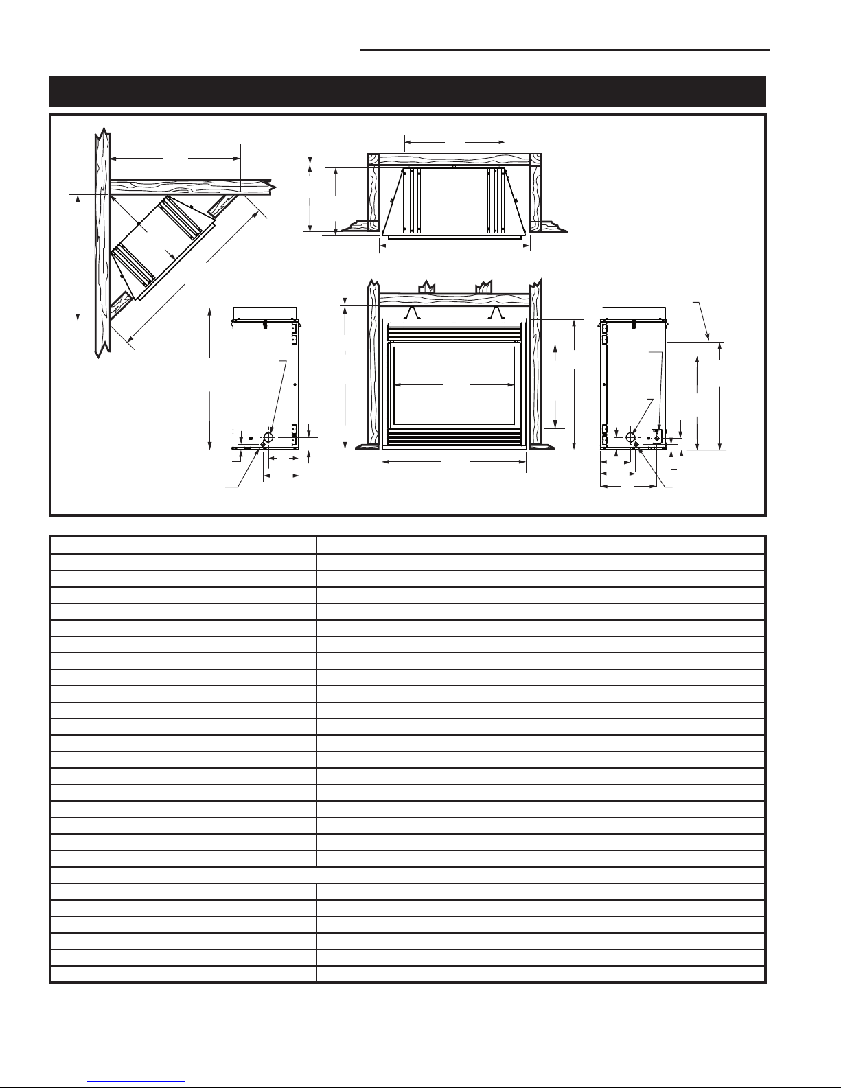
Fireplace Dimensions - Rear Vent
*
*
*
*
Fig. 1 Fireplace specifications and framing dimensions.
Ref. 36CDVXR
A 35¹⁄₄” (895 mm)
B 34³⁄₄” (883 mm)
C 32¹⁄₈” (816 mm)
D 33” (838 mm)
E 21¹⁄₈” (537 mm)
F 16⁵⁄₈” (422 mm)
G 25” (635 mm)
H 18¹⁄₂” (470 mm)
I 22” (559 mm)
J 3¹⁄₄” (83 mm)
K 2⁷⁄₈” (73 mm)
L 1³⁄₈” (35 mm)
M 14” (356 mm)
N 8¹⁄₂” (216 mm)
O 7³⁄₈” (187 mm)
P 1³⁄₈” (35 mm)
Q 3¹⁄₄” (83 mm)
R 7³⁄₈” (187 mm)
S 8¹⁄₂” (216 mm)
Framing Dimensions If using Rigid 45° with Starter Pipe
T* 68¹⁄₄“ (1734 mm) 58³⁄₈” (1483 mm)
U* 48¹⁄₄“ (1226 mm) 41³⁄₈” (1051 mm)
V* 34¹⁄₈” (867 mm) 29¹⁄₈” (740 mm)
W 17¹⁄₈” (435 mm)
X 36¹⁄₄” (921 mm)
Y 35” (889 mm)
* Must be adhered to if using 7TCD45KT Flex Vent Kit
4
20012253
CDVX Series Direct Vent Gas Fireplace
O
F
X - Minimum Rough
Opening Width
Minimum
Rough
Opening
Height
Minimum
Rough
Opening
Depth
U
U
V
T
W
G
J
E
A
Y
B
K
L
Q
Gas Line
Access
Gas Line
Access
Low Voltage
Electrical
Access
Electrical
Access
D
N
Low
Voltage
Access
P
R
S
C
M
H
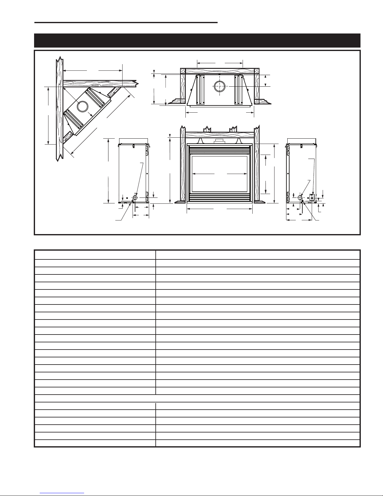
Fireplace Dimensions - Top Vent
Fig. 2 Fireplace specifications and framing dimensions.
Ref. 36CDVXT
A 35¹⁄₄” (895 mm)
B 34³⁄₄” (883 mm)
C 32¹⁄₈” (816 mm)
D 33” (838 mm)
E 21¹⁄₈” (537 mm)
F 16⁵⁄₈” (422 mm)
G 25” (635 mm)
H 8” (203 mm)
J 3¹⁄₄” (83 mm)
K 2⁷⁄₈” (73 mm)
L 1³⁄₈” (35 mm)
M 14” (356 mm)
N 8¹⁄₂” (216 mm)
O 7³⁄₈” (187 mm)
P 1³⁄₈” (35 mm)
Q 3¹⁄₄” (83 mm)
R 7³⁄₈” (187 mm)
S 8¹⁄₂” (216 mm)
Framing Dimensions
T 58³⁄₈“ (1483 mm)
U 41³⁄₈“ (1051 mm)
V 29¹⁄₈” (740 mm)
W 17¹⁄₈” (435 mm)
X 36¹⁄₄” (921 mm)
Y 35” (889 mm)
20012253
5
CDVX Series Direct Vent Gas Fireplace
J
F
G
H
I
Mantel
Leg
O
N
M
L
K
A B C D E
V
W
X
Y
Z
Fireplace
Y
E
A
B
C
D
F
Y
B
X
X
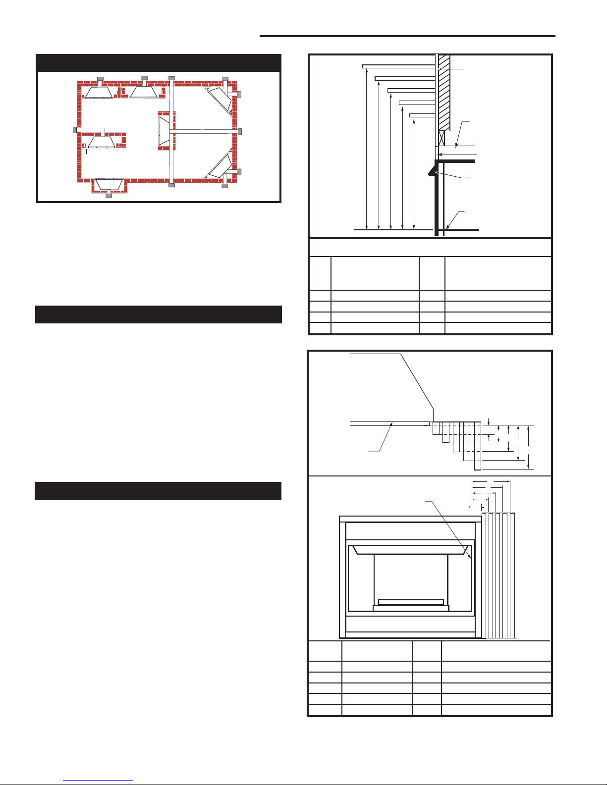
Locating Your Fireplace
LU584-R
Fig. 3 Locate gas fireplace.
A) Flat on wall B) Cross corner C) **Island
D) Room divider E) Flat on wall corner F) Chase installation
Y) Refer to “Clearance to Combustibles” Section
NOTE: (Fig. 3)
** Island (C) and Room Divider (D) installation is possible as
long as the horizontal portion of the vent system (X) does not
exceed 20’ (6 m) with a minimum vertical of 4’ (122 cm). See
details in Venting Section.
Clearance to Combustibles
Top of Unit to Ceiling ............................... 36” (914 mm)
Front of Unit to Combustibles .................. 36” (914 mm)
Appliance
Top .......................................................... 0” (0 mm)
Bottom ..................................................... 0” (0 mm)
Side ......................................................... 0” (0 mm)
Back ........................................................ 0” (0 mm)
Venting
Concentric sections of DV Vent
Top, bottom & sides .............................. 1” (25 mm)
NOTE: Hood must be permanently installed with
three (3) sheet metal screws supplied in fireplace.
(Refer to hood installation in this manual.)
Finish Wall
Standoff
Noncombustible
Material
Hood
Top of Combustion
Chamber
CFM146
Mantel Chart
Mantel Shelf or Mantel from Top of
Ref. Breast Plate Depth Ref. Combustion Chamber
V 10” (254 mm) A 17” (432 mm)
W 8” (203 mm) B 15” (381 mm)
X 6” (152 mm) C 13” (330 mm)
Y 4” (101 mm) D 11” (279 mm)
Z 2” (51 mm) E 9” (229 mm)
Fig. 4a Combustible mantel minimum installation.
Black
Surround
Face
CFM164a
Mantels
The height that a combustible mantel is fitted above the
fireplace is dependent on the depth of the mantel. This
also applies to the distance between the mantel leg (if
fitted) and the fireplace.
For the correct mounting height and widths refer to
Figs. 4a and 4b, and the following Mantel Charts.
The fitting of a bay window trim kit does not effect
the distances and reference points referred to in the
diagram and chart.
Noncombustible mantels and legs may be installed at
any height and width around the appliance.
When using paint or lacquer to finish the mantel, such
paint or lacquer must be heat resistant to prevent
discoloration.
6
Side of
Combustion Chamber
CFM170
Mantel Mantel Leg FromSide
Ref. Leg Depth Ref. of Comb. Opening
F 10” (254 mm) K 11¹⁄₂” (292 mm)
G 8” (203 mm) L 9
¹⁄₂” (241 mm)
H 6” (152 mm) M 7¹⁄₂” (191 mm)
I 4” (101 mm) N 5
¹⁄₂” (140 mm)
J 2” (51 mm) O 3¹⁄₂” (89 mm)
Fig. 4b Combustible mantel leg minimum installation.
20012253
CDVX Series Direct Vent Gas Fireplace
A
B
Hearth
A hearth is not mandatory but is recommended for
aesthetic purposes. We recommend a noncombustible
hearth which projects out 12” (305 mm) or more from
Flange Drywall
Position Depth
A 1/2” / 13 mm
B 5/8” / 16 mm
Flange Location for Desired
Drywall Depth at Stud Wall
the front of the fireplace.
Cold climate installation recommendation:
When installing this unit against a
non-insulated exterior wall or chase,
it is mandatory that the outer walls
be insulated to conform to applicable
insulation codes.
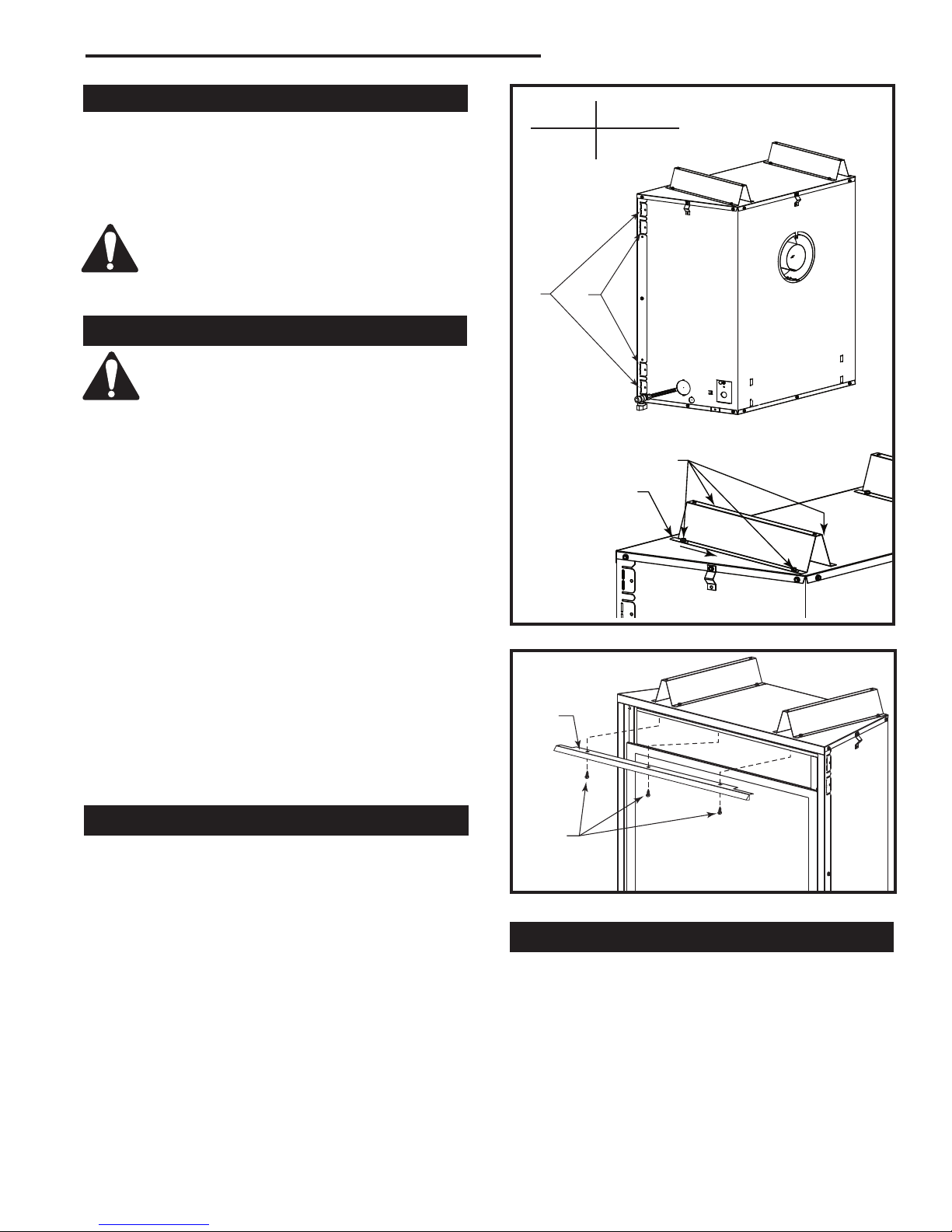
Framing and Finishing
Check fireplace to make sure it is levelled
and properly positioned.
To mount the appliance:
1. Choose the location.
2. This unit comes with four (4) flanges pre-mounted
Standoff Location for Desired Finish Wall Depth at
Header
Screws
on both sides of the fireplace to allow two different
drywall thicknesses to be used. Flange “A” is for 1/2”
Tabs
drywall while flange “B” is for 5/8” drywall.
3. Bend the desired flanges out 90° on both sides of
the fireplace. Slide the fireplace into the framed
opening until the flanges contact the front surfaces
of the framing. Level the unit and secure it firmly in
place.
4. The standoffs are adjustable for different drywall
thicknesses. The unit is shipped from the factory at
Fig. 5 Nailing flanges and standoffs.
1/2” (13 mm). Loosen the four (4) screws securing
each standoff to the top of the fireplace. Slide the
standoff back. Tighten the screws. This yields a 5/8”
(16 mm) thick drywall space. Removing the standoff
Hood
and having the tabs on the standoff face the rear of
the unit yields a 3/4” (19 mm) drywall space. (Fig. 5)
NOTE: Drywall must stop at standoffs and not touch
top of unit.
Sheet
Hood Installation
Metal
Screws
CAUTION: Hood MUST be permanently installed.
1. Remove top louvre. Carefully remove hood from
inside top louvre opening.
2. Remove three (3) sheet metal screws in bottom
flange of fireplace surround top.
Fig. 6 Secure hood to fireplace with sheet metal screws.
Final Finishing
3. Install the hood by aligning the three holes in bottom
flange of fireplace surround top. (Fig. 6)
4. Secure hood to bottom flange of fireplace surround
top using three screws removed in Step 2. (Fig. 6)
5. Carefully remove protectors under the relief plates
on top of the firebox.
Noncombustible materials such as brick or tile may be
extended over the edges of the face of the fireplace.
DO NOT cover any vent or grille panels.
If a Trim Kit is going to be installed on the fireplace, the
brick or tile will have to be installed flush with the edges
of the fireplace.
6. Replace top louvre.
FP1603
FP1603a
FP1609
20012253
7
CDVX Series Direct Vent Gas Fireplace
TP
TH
TP
TH
Gas Specifications
Max. Min.
Input Input
Model Fuel Gas Control BTU/h BTU/h
36CDVXRRN Nat Millivolt 21,000 14,700
36CDVXRRP* Prop Millivolt 21,000 15,750
36CDVXTRN Nat Millivolt 21,000 14,700
36CDVXTRP* Prop Millivolt 21,000 15,750
*Using conversion kit
Gas Inlet and Manifold Pressures
Natural LP (Propane)
Inlet Minimum 5.5” w.c. 11.0” w.c.
Inlet Maximum 14.0” w.c. 14.0” w.c.
Manifold Pressure 3.5” w.c. 10.0” w.c.
High Elevations
Input ratings are shown in BTU per hour and are
certified without deration for elevations up to
4,500 feet (1,370 m) above sea level.
For elevations above 4,500 feet (1,370 m) in USA,
installations must be in accordance with the current ANSI Z223.1/NFPA 54 and/or local codes having jurisdiction.
In Canada, please consult provincial and/or local
authorities having jurisdiction for installations at
elevations above 4,500 feet (1,370 m).
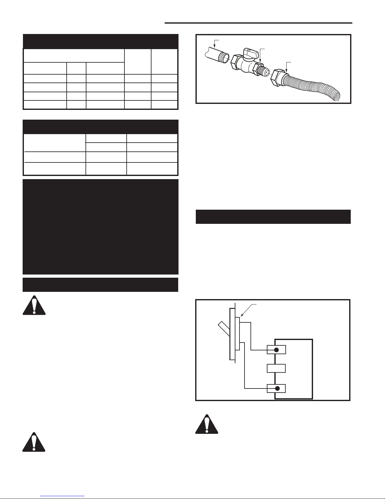
Gas Line Installation
When purging the gas lines, the front window frame assembly must be removed.
The gas pipeline can be brought in through the rear
of the appliance as well as the bottom. Knockouts are
provided on the bottom behind the valve to allow for the
gas pipe installation and testing of any gas connection.
It is most convenient to bring the gas line in from the
rear right side of the valve as this allows fan installation
or removal without disconnecting the gas line.
The gas line connection can be made with properly
tinned 3/8” copper tubing, 3/8” rigid pipe or an approved flex connector. Since some municipalities have
additional local codes, it is always best to consult your
local authority and the National Fuel Gas Code, ANSI
Z223.1/NFPA 54 in the USA or the CSA-B149.1 installation code.
Always check for gas leaks with a mild
soap and water solution. Do not use an
open flame for leak testing.
1/2” Gas Supply
1/2” NPT x 1/2” Flare Shutoff Valve
3/8” Flex Line
(From Valve)
FP297A
Fig. 7 Typical gas supply installation.
The gas control is equipped with a captured screw type
pressure test point, therefore it is not necessary to provide a 1/8” test point up stream of the control.
When using copper or flex connector use only approved
fittings. Always provide a union when using black iron
pipe so the gas line can be easily disconnected for
burner or fan servicing. See gas specification for pressure details and ratings.
The fireplace valve must not be subjected to any test
pressures exceeding 1/2 psi. Isolate or disconnect this
and any other gas appliance control from the gas line
when pressure testing.
Remote ON/OFF Switch
Installation
1. Carefully unwrap the remote wire that is attached to
the valve. There are two 1/2” (13 mm) knockouts,
one on each side of the outer casing.
2. Remove the knockout desired and insert the plastic
snap bushing on the remote wire in the 1/2” hole.
Feed the remote wire through the outer casing.
3. Attach the wire to an ON/OFF switch and install the
switch into the receptacle box. (Fig. 8)
Remote ON/OFF Switch
or Thermostat
or Remote Control
Gas
Control
Valve
FP1224
Fig. 8 Remote switch wiring diagram.
Do not wire the remote ON/OFF wall switch
for the gas fireplace to the 120 volt power
supply.
8
20012253
CDVX Series Direct Vent Gas Fireplace
OUTSIDE
INSIDE
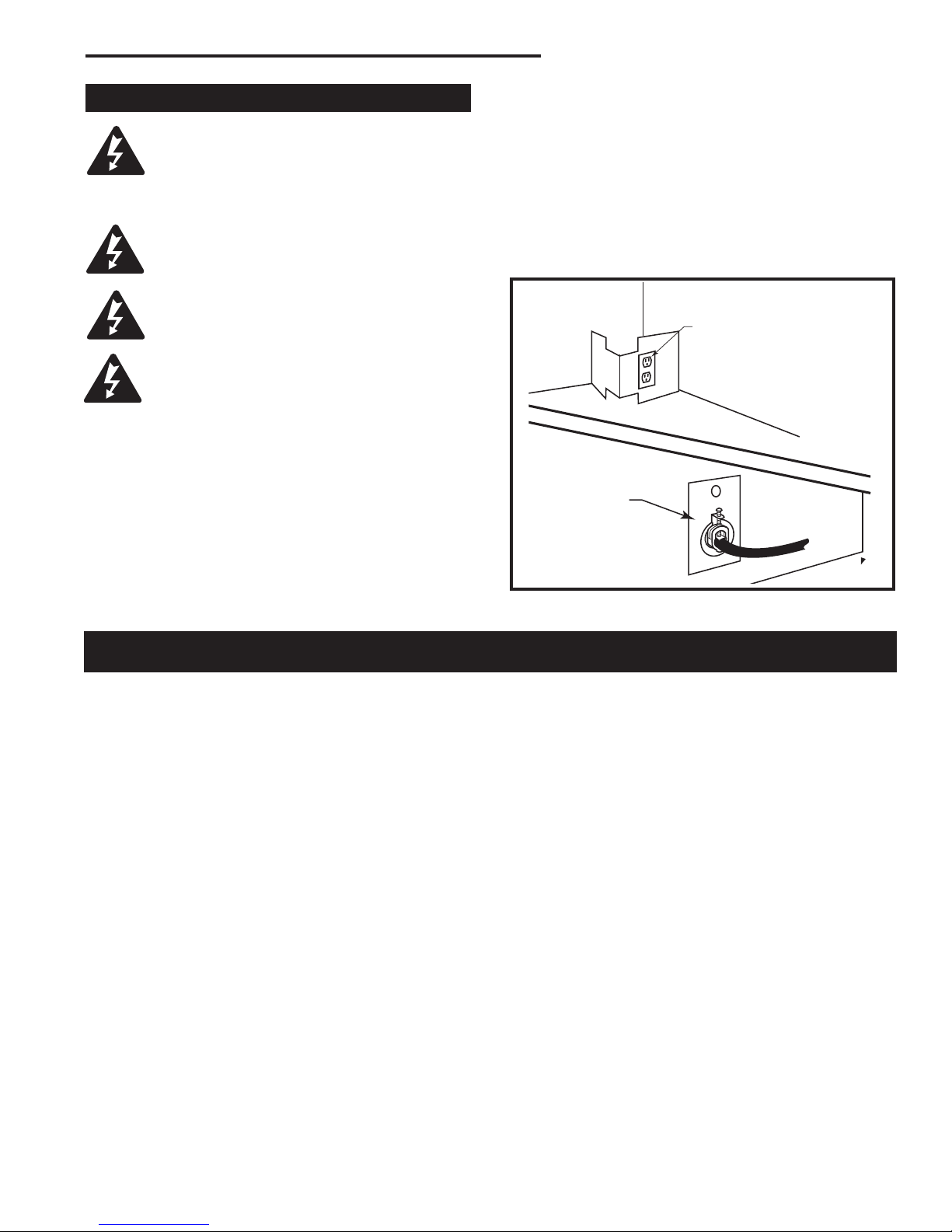
120V Electrical Hook Up
The fireplace, when installed, must be
electrically connected and grounded in
accordance with local codes or, in the absence of local codes, with the current CSA
C22.1 Canadian Electrical Code.
For USA installations follow local codes
and the national electrical code ANSI/
NFPA No. 70.
It is strongly suggested that wiring of the
Electrical Junction Box be carried out by a
licensed electrician.
Ensure that the power to the supply line
has been disconnected before commencing this procedure.
The electrical junction box has been fitted standard on
this model to allow for the easy connection of an optional fan kit.
To connect the electric box to the house electrical sup
ply follow the steps below.
1. Unscrew the retaining screw holding the electric
cover to the outside of the unit. (Fig. 9)
2. Remove the knockout from the electric cover plate.
3. Insert the wire connector through the hole in the
electric cover plate and secure.
4. Insert the house wire through the connector on the
cover plate.
5. Secure the wires from the receptacle to the incoming
line.
6. The receptacle has four wires connected to it. The
receptacle is set up for a split system. The top plug
of the receptacle is wired separately from the bottom
one.
7. Green is ground. White is neutral, Black and red are
line voltage to each plug on the receptacle.
Electric Receptacle
-
Fig. 9 Electric receptacle.
Electric Receptacle
Cover Plate
FP1597
General Venting
Your fireplace is approved to be vented either through
the side wall, or vertically through the roof.
• Only CFM Corporation venting components specifi-
cally approved and labelled for this fireplace may be
used.
• Vent terminations shall not be recessed into a wall or
siding.
• Horizontal venting which incorporates the twist lock
pipe must be installed on a level plane without an
inclining or declining slope.
• Horizontal venting which incorporates the use of flex
venting shall have an inclining slope from the unit of
1” (25 mm) per 24” (610 mm).
There must not be any obstruction such as bushes,
garden sheds, fences, decks or utility buildings within
24” (610mm) from the front of the termination hood.
Do not locate termination hood where excessive snow
or ice build up may occur. Be sure to check vent termination area after snow falls, and clear to prevent accidental blockage of venting system. When using snow
blowers, make sure snow is not directed towards vent
termination area.
Location of Vent Termination
It is imperative the vent termination be located observing the minimum clearances as shown on the next
page.
*Check with local codes or in absence of same with
CSAB149.1 Installation Codes (1991) for Canada or follow the current National Fuel Gas Code, ANSI Z223.1/
NFPA 54 for installations in the USA.
20012253
9
CDVX Series Direct Vent Gas Fireplace
V
V
V
V
V
V
V
X
X
X
D
E
B
B
B
C
B
M
B
A
J
K
F
L
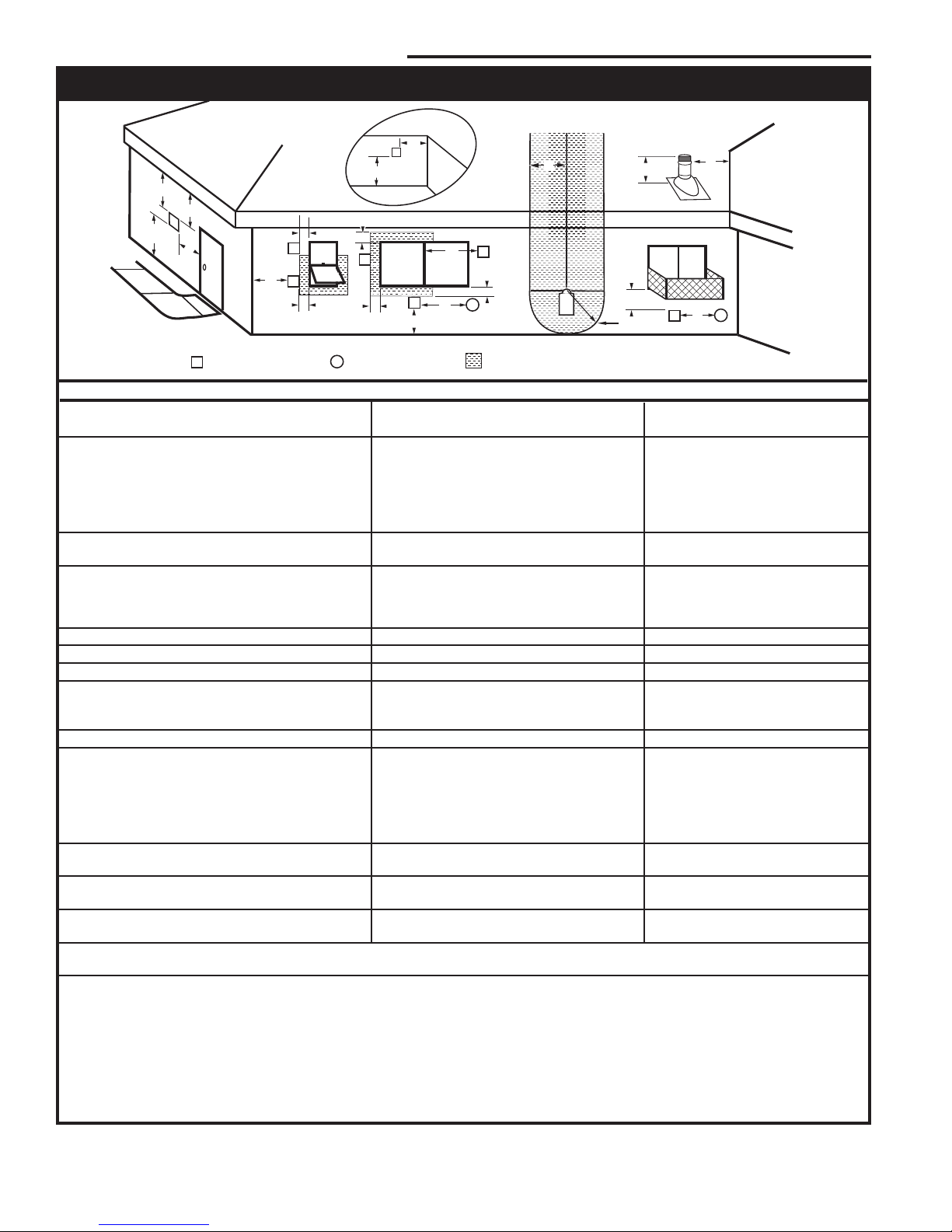
VENT TERMINATION AIR SUPPLY INLET
AREA WHERE TERMINAL IS NOT PERMITTED
H
I
Operable
Operable
Fixed
Closed
V
B
INSIDE
CORNER DETAIL
V
A
G
N
N
CFM145a
General Venting Information - Termination Location
Canadian Installations1 US Installations
2
A = Clearance above grade, veranda, porch, 12” (30cm) 12” (30cm)
deck, or balcony
B = Clearance to window or door that may be 6” (15cm) for appliances 6” (15cm) for appliances
opened < 10,000Btuh (3kW), 12” (30cm) < 10,000 Btuh (3kW), 9”
for appliances > 10,000 Btuh (3kW) and (23cm) for appliances > 10,000
< 100,000 Btuh (30kW), 36” (91cm) Btuh (3kW) and < 50,000 Btuh
for appliances > 100,000 Btuh (30kW) (15kW), 12” (30cm) for
appliances > 50,000 Btuh (15kW)
C = Clearance to permanently closed window 12” (305mm) recommended to 12” (305mm) recommended to
prevent window condensation prevent window condensation
D = Vertical clearance to ventilated soffit located
above the terminal within a horizontal 18” (458mm) 18” (458mm)
distance of 2’ (610mm) from the center
line of the terminal
E = Clearance to unventilated soffit 12” (305mm) 12” (305mm)
F = Clearance to outside corner see next page see next page
G = Clearance to inside corner (see next page) see next page see next page
H = Clearance to each inside of center line 3’ (91cm) within a height of 15’ (5m) 3’ (91cm) within a height of 15’
extended above meter/regulator assembly above the meter/regulator assembly (5m) above the meter/regulator
assy
I = Clearance to service regulator vent outlet 3’ (91cm) 3’ (91cm)
J = Clearance to nonmechanical air supply inlet 6” (15cm) for appliances < 10,000 6” (15cm) for appliances
to building or the combustion air inlet to any Btuh (3kW), 12” (30cm) for < 10,000 Btuh (3kW), 9”
other appliances appliances > 10,000 Btuh (3kW) and (23cm) for appliances > 10,000
< 100,000 Btuh (30kW), 36” (91cm) Btuh (3kW) and < 50,000 Btuh
for appliances > 100,000 Btuh (30kW) (15kW), 12” (30cm) for
appliances > 50,000 Btuh (15kW)
K = Clearance to a mechanical air supply inlet 6’ (1.83m) 3’ (91cm) above if within 10
feet (3m) horizontally
L = Clearance above paved sidewalk or paved 7’ (2.13m)† 7’ (2.13m)†
driveway located on public property
M = Clearance under veranda, porch, deck or 12” (30cm)‡ 12” (30cm)‡
balcony
N = Clearance above a roof shall extend a minimum of 24” (610mm) above the highest point when it passes through the roof
surface, and any other obstruction within a horizontal distance of 18” (450mm).
1 In accordance with the current CSA-B149 Installation Codes
2 In accordance with the current ANSI Z223.1/NFPA 54 National Fuel Gas Codes
† A vent shall not terminate directly above a sidewalk or paved driveway which is located between two single family dwellings and
serves both dwellings
‡ only permitted if veranda, porch, deck or balcony is fully open on a minimum 2 sides beneath the floor:
NOTE: 1. Local codes or regulations may require different clearances.
2. The special venting system used on Direct Vent Fireplaces are certified as part of the appliance, with clearances tested and
approved by the listing agency.
3. CFM Corporation assumes no responsibility for the improper performance of the appliance when the venting system does not
meet these requirements.
Fig. 10 Vent termination locations.
10
20012253
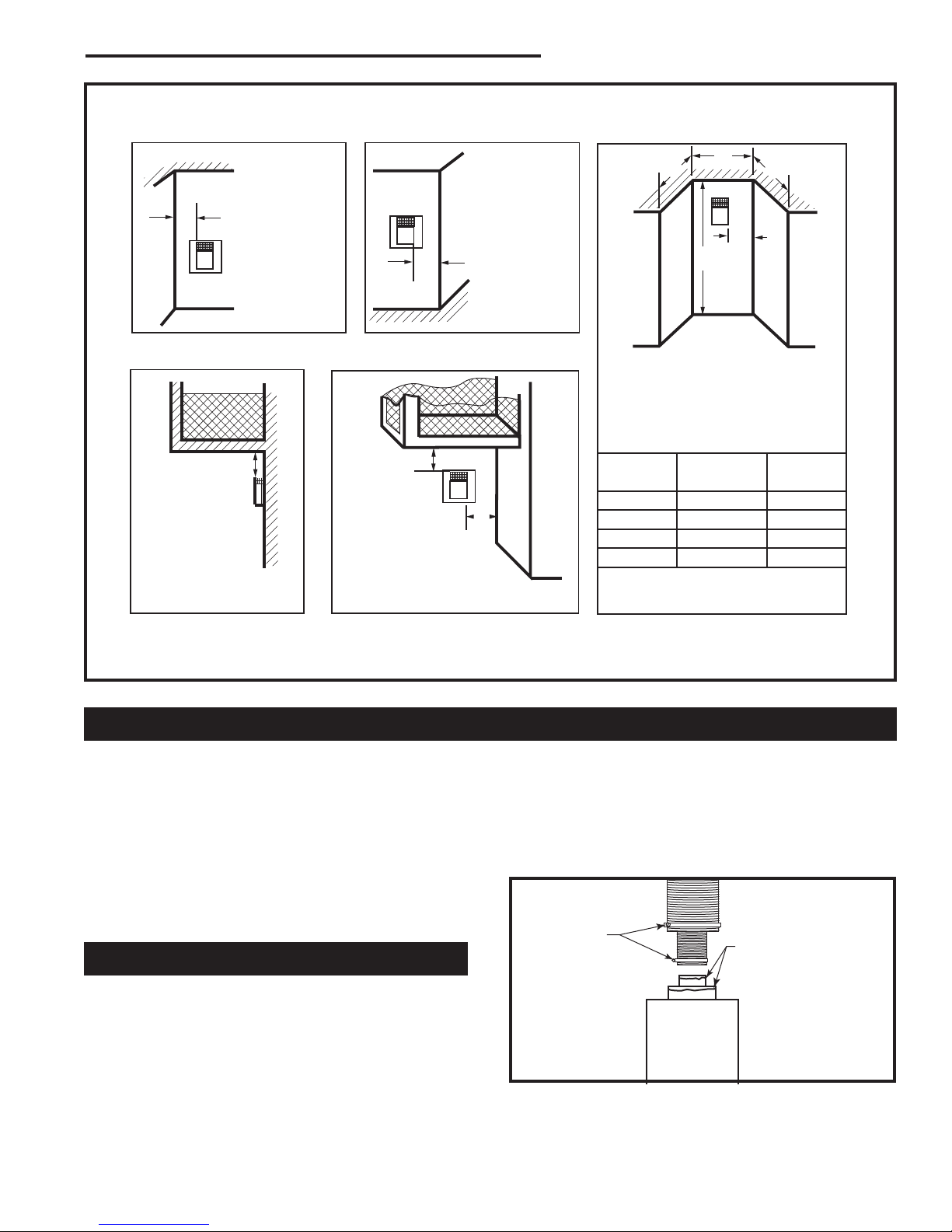
Outside Corner
Inside Corner
Termination Clearances
Termination clearances for buildings with combustible and noncombustible exteriors.
G =
Combustible
6" (152 mm)
Noncombustible
2" (51 mm)
F =
Combustible
6" (152 mm)
Noncombustible
2" (51 mm)
G
Balcony with no side wall
M =
Combustible &
Noncombustible
12" (305 mm)
M
Balcony with perpendicular side wall
M = 24" (610 mm)
P = 20” (508 mm)
M
F
Alcove Applications*
C
D
C
E
V
V
Combustible &
Noncombustible
V
V
V
E = Min. 6” (152 mm) for
non-vinyl sidewalls
Min. 12” (305 mm) for
vinyl sidewalls
O = 8’ (2.4 m) Min.
O
P
*NOTE: Termination in an alcove space (spaces open only on one side and with an overhang) is permitted with the dimensions
specified for vinyl or non-vinyl siding and soffits. 1. There must be a 3’ (914 mm) minimum between termination caps. 2. All
mechanical air intakes within 10’ (1 m) of a termination cap must be a minimum of 3’ (914 mm) below the termination cap. 3. All
gravity air intakes within 3’ (914 mm) of a termination cap must be a minimum of 1’ (305 mm) below the termination cap.
Fig. 11 Termination clearances.
Canadian Installations:
General Information Assembling Vent Pipes
Venting system must be installed in accordance with the
current CSA-B149.1 installation code.
USA Installations:
The venting system must conform with local codes and/
or the current National Fuel Gas code ANSI Z223.1/
NFPA 54.
Only venting components manufactured by CFM Corporation can be used in Direct Vent systems.
Flex Vent Pipes
Before joining the flex vent pipe to the unit, apply a
bead of high temperature sealant* (provided) to the 4”
pipe exiting the fireplace. Secure flex vent pipe in place
with a hose clamp (provided).
*Be sure the flex pipe overlaps at least 1” (25 mm) onto
the collars of the fireplace and termination. If the termination has an internal bead, be sure to overlap and
secure 1” (25 mm) past the bead.
20012253
CDVX Series Direct Vent Gas Fireplace
No.
of Caps D
1 3’ (914 mm) 2 x D
2 6’ (1.8 m) 1 x D
3 9’ (2.7 m) 2/3 x D
4 12’ (3.7 m) 1/2 x D
D
= # of Termination caps x 3
Min.
C
= (2 / # termination caps) x D
Max.
* Be sure the vent is actually crushed before proceeding. Apply a tug to be sure the vent will not slip off the
collars.
Repeat process with 7” flex vent pipe. The same procedure must be performed on the vent side.
Hose Clamp
Fig. 12 Apply high temperature sealant to 4” and 7” pipes.
C
Min.
Apply High Tempera
ture Sealant
Max.
Actual
Actual
Actual
Actual
Actual
584-15
-
FP1471a
11
CDVX Series Direct Vent Gas Fireplace
3
4
5
6
7
8
9
10
11
12
13
14
15
16
17
18
19
20
21
22
23
24
25
26
27
28
29
30
3 4 5 6 7 8 9 10 11 12 13 14 15 16 17 18 19 20
eg: A
eg: B
Twist Lock Pipes
When using CFM Corporation twist-lock pipe, it is not
necessary to use sealant on the joints. The only areas
of the venting system that need to be sealed with high
temperature silicone sealant are the sliding joint of any
telescopic vent section used in the system.
To join the twist lock pipes together, simply align the
beads of the male end with the grooves of the female
end, then while bringing the pipe together, twist the pipe
until the flange on the female end contacts the external
flange on the male end. It is recommended that you
secure the joints with three (3) sheet metal screws,
however this is not mandatory with twist lock pipe.
To make it easier to assemble the joints we suggest
putting a lubricant (Vaseline or similar) on the male end
of the twist lock pipe prior to assembly.
Male End Female End
Vertical dimension from the floor of the unit
to the center of the horizontal vent pipe
Screw Holes
Fig. 13 Twist-lock pipe joints.
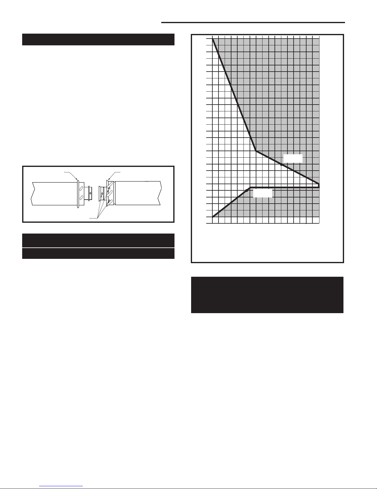
36CDVXR Venting
How to Use the Vent Graph
The vent chart should be read in conjunction with the
following vent installation instructions to determine the
relationship of the vertical and horizontal dimensions of
the vent system.
1. Determine the height of the center of the horizontal
vent pipe exiting through the outer wall. Using this
dimension on the Sidewall Vent Graph (Fig. 14)
locate the point intersecting with slanted graph line.
2. From the point of this intersection, draw a vertical
line to the bottom of the graph.
3. Select the indicated dimension, and position the
fireplace in accordance with same.
Example A:
If the vertical dimension from the floor of the
fireplace is 11’ (3.4 m) the horizontal run to the face
of the outer wall must not exceed 14’ (4.3 m).
Example B:
If the vertical dimension from the floor of the unit is
7’ (2.14 m), the horizontal run to the face of the outer
wall must not exceed 8¹⁄₂’ (2.6 m).
12
TWL100
Horizontal dimension from the outside face of the
wall to the center of the fireplace vent flange
Sidewall vent graph showing the relationship between vertical
and horizontal dimensions for a Direct Vent flue system.
Fig. 14 Sidewall venting graph. (Dimensions in feet)
Rear Wall Venting Applications
* Exterior Outside Wall
7” (178 mm) to 20” (508 mm)
From Rear of Unit *
With this application, the following rigid pipe kits may be
used:
7” to 13” (178 - 330 mm) to outside wall: 7TCRVT
13” to 20” (330 - 305 mm) to outside wall: 7TCRVT1320
45° elbow with 20” (508 mm) Starter for corner applications
When installed as a rear vent unit this appliance may be
vented directly to a termination located on the rear wall
behind the appliance.
• Only CFM Corporation venting components are
approved to be used in these applications. (Refer to
“Venting Components” listed for different installation
requirements)
• The maximum straight out the back horizontal
distance between the rear of the appliance and
the outside face of the rear wall is 20” (508 mm).
The minimum is 7” (178 mm). (Fig. 15)
20012253
 Loading...