

Temco 33RDVN, 36RDVN, 39RDVN Installation And Owner's Manual
INSTALLER/CONSUMER
CER TIF IED
D
E
S
I
G
N
C
E
R
T
I
F
I
E
D
SAFETY INFORMATION
PLEASE READ THIS MANUAL
BEFORE INSTALLING AND
USING APPLIANCE
WARNING!
IF THE INFORMATION IN THIS
MANUAL IS NOT FOLLOWED
EXACTLY, A FIRE OR
EXPLOSION MAY RESULT
CAUSING PROPERTY DAMAGE,
PERSONAL INJURY OR LOSS
OF LIFE.
FOR YOUR SAFETY
Installation and service must
be performed by a qualified
installer, service agency or the
gas supplier.
WHAT TO DO IF YOU SMELL GAS:
• Do not try to light any appliance.
• Do not touch any electric switch;
do not use any phone in your
building.
• Immediately call your gas
supplier from your neighbor’s
phone. Follow the gas suppliers
instructions.
• If you cannot reach your gas
supplier call the fire department.
DO NOT STORE OR USE
GASOLINE OR OTHER
FLAMMABLE VAPORS AND
LIQUIDS IN THE VICINITY OF
THIS OR ANY OTHER
APPLIANCE.
WARNING: Improper installation,
adjustment, alteration, service or
maintenance can cause injury or
property damage. Refer to this
manual. For assistance or additional
information, consult a qualified
installer, service agency or the gas
supplier.
Builder Rear Vent Direct
Vent Zero Clearance Gas
Fireplace Heater
Models: 33RDVN, 36RDVN,
39RDVN
Installation Instructions and
Homeowner’s Manual
INSTALLER: Leave this manual with the appliance.
CONSUMER: Retain this manual for future reference.
20007628 5/08 Rev. 8

RDVN Series Direct Vent Gas Fireplace
Table of Contents
PLEASE READ THE INSTALLATION & OPERATING INSTRUCTIONS BEFORE USING THIS APPLIANCE.
Thank you and congratulations on your purchase of a CFM Corporation fireplace.
IMPORTANT: Read all instructions and warnings carefully before starting installation.
Failure to follow these instructions may result in a possible fire hazard and will void the warranty.
Installation & Operating Instructions
General Information, Warnings, Cautions ............................................................................................3
Requirements for the Commonwealth of Massachusetts ....................................................................4
Fireplace Dimensions ..........................................................................................................................
Locating Your Fireplace .......................................................................................................................6
Clearance to Combustibles .................................................................................................................
Mantels .............................................................................................................................................6
Hearth .............................................................................................................................................7
Framing & Finishing .............................................................................................................................
Final Finishing .....................................................................................................................................7
Gas Specifications ...............................................................................................................................
Gas Inlet and Manifold Pressures .......................................................................................................7
High Elevations ....................................................................................................................................7
Gas Line Installation ............................................................................................................................
Remote Switch Installation ..................................................................................................................8
Alternate Switch Location ....................................................................................................................
EB-1 Electrical Box ..............................................................................................................................9
General Venting Information
General Venting .................................................................................................................................
General Venting Information-Termination Location ..........................................................................11
General Information on Assembling Vent Pipes ................................................................................
Flex Vent Pipes ..................................................................................................................................12
Twist Lock Pipes ................................................................................................................................13
How to Use the Vent Graph ...............................................................................................................
Rear Wall Vent Application & Installation ...........................................................................................13
Vertical Sidewall Applications & Installation .......................................................................................
Below Grade Installations.. ................................................................................................................19
Vertical Through-the-Roof Applications & Installation ........................................................................20
Venting Components .........................................................................................................................
Operating Instructions
Glass Information ..............................................................................................................................
Louvre Removal ................................................................................................................................23
Window Frame Assembly Removal ...................................................................................................23
Glass Cleaning ..................................................................................................................................
Installation of Logs, Lava Rock & Ember Material ............................................................................24
Flame & Temperature Adjustment .....................................................................................................
Flame Characteristics ........................................................................................................................25
Lighting & Operating Instructions ......................................................................................................26
Troubleshooting .................................................................................................................................
Fuel Conversion Instructions .............................................................................................................30
Maintenance
Unit Adjustment .................................................................................................................................33
Maintenance ......................................................................................................................................33
Replacement Parts ........................................................................................................................................36
Optional Accessories
Fan Kits ...........................................................................................................................................
Wiring Instructions .............................................................................................................................39
Ceramic Refractory Kits .....................................................................................................................39
Decorative Bay Windows ...................................................................................................................39
Bay Window Screen ..........................................................................................................................40
Remote Controls ................................................................................................................................40
Warranty .........................................................................................................................................................44
Installation and Startup Checklist ...............................................................................................................45
Warranty Registration
...................................................................................................................................48
5
6
7
7
8
9
10
12
13
15
22
23
23
25
27
38
2
20007628
RDVN Series Direct Vent Gas Fireplace
�
Installation & Operating Instructions
This gas fireplace should be installed by a qualified installer,
preferably NFI or WETT (Canada) certified, in accordance with
local building codes and with current CSA-B149.1 Installation
codes for Gas Burning Appliances and Equipment. For USA
Installations follow local codes and/or the current National Fuel
Gas Code. ANSI Z223.1/NFPA 54.
FOR SAFE INSTALLATION AND OPERATION PLEASE NOTE
THE FOLLOWING:
1 . This fireplace gives off high temperatures and should be
located out of high traffic areas and away from furniture and
draperies.
2. Children and adults should be alerted to the hazards of the
high surface temperatures of this fireplace and should stay
away to avoid burns or ignition of clothing.
3. CAUTION: Due to high glass surface temperature chil-
dren should be carefully supervised when in the same
room as fireplace.
4. Under no circumstances should this fireplace be modified.
Parts removed for servicing should be replaced prior to
operating this fireplace again.
5. Installation and any repairs to this fireplace must be per
formed by a qualified installer, service agency or gas sup
plier. A professional service person should be contacted to
inspect the fireplace annually. More frequent cleaning may
be required due to excess lint and dust from carpeting, bedding material, etc.
6. Control compartments, burners and air passages in this fire
place should be kept clean and free of dust and lint. Make
sure that the gas valve and pilot light are turned off before
you attempt to clean this fireplace.
7. The venting system (chimney) of this fireplace should be
checked at least once a year and if needed your venting
system should be cleaned.
8. Keep the area around your fireplace clear of combustible
materials, gasoline and other flammable vapour and liquids.
This fireplace should not be used as a dry-ing rack for cloth
ing, nor should Christmas stockings or decorations be hung
on or around the fireplace.
9. Under no circumstances should any solid fuels (wood, coal,
paper or cardboard etc.) be used in this fireplace.
10. The flow of combustion and ventilation air must not be ob
structed in any way.
11. When the fireplace is installed directly on carpeting, vinyl tile
or any combustible material other than wood, this fireplace
must be installed on a metal or wood panel extending the
full width and depth of the fireplace.
12. This fireplace requires adequate ventilation and combustion
air to operate properly.
-
-
-
13. This fireplace must not be connected to a chimney flue
serving a separate solid fuel burning fireplace.
14. When the fireplace is not in use it is recommended that the
gas control valve be left in the OFF position.
15. These units have been approved for bedroom use.
33RDVN / 36RDVN / 39RDVN
Certified To
ANSI Z21.88-2005 / CSA 2.33-2005 / UL307B
Vented Gas Fireplace Heaters
WARNING: Check with your electronics manufacturer
before installing a television or other electronic device above this fireplace.
This appliance may be installed in an aftermarket
permanently located, manufactured home or mobile
home, where not prohibited by local codes.
This appliance is only for use with the type of gas
indicated on the rating plate. This appliance is not
convertible for use with other gases, unless a certified
kit is used.
IMPORTANT:
PLEASE REVIEW THE FOLLOWING CAREFULLY
Remove any plastic from from parts before turning the fireplace ON.
It is normal for fireplaces fabricated of steel to give off some
expansion and/or contraction noises during the start up or
cool down cycle. Similar noises are found with your furnace
heat exchanger or car engine.
It is not unusual for your gas fireplace to give off some odor
the first time it is burned. This is due to the curing of the paint
and any undetected oil from the manufacturing process.
Please ensure that your room is well ventilated-open all
windows.
It is recommended that you burn your fireplace for at least ten
four (4) hours the first time you use it. If the optional fan kit
has been installed, place the fan switch in the “OFF” position
during this time.
Proposition 65 Warning: Fuels used in gas, woodburning or oil fired appliances, and the products of
combustion of such fuels, contain chemicals known to
-
the State of California to cause cancer, birth defects
and other reproductive harm.
California Health & Safety Code Sec. 25249.6
20007628
3

RDVN Series Direct Vent Gas Fireplace
Installation & Operating Instructions
Requirements for the Commonwealth of
Massachusetts
All gas fitting and installation of this heater shall only be
done by a licensed gas fitter or licensed plumber.
For all side wall horizontally vented gas fueled
equipment installed in every dwelling, building or
structure used in whole or in part for residential
purposes, including those owned or operated by the
Commonwealth and where the side wall exhaust vent
termination is less than seven (7) feet above finished
grade in the area of the venting, including but not limited
to decks and porches, the following requirements shall
be satisfied:
Installation of Carbon Monoxide Detectors
At the time of installation of the side wall horizontal
vented gas fueled equipment, the installing plumber
or gas fitter shall observe that a hard wired carbon
monoxide detector with an alarm is installed on each
additional level of the dwelling, building or structure
served by the side wall horizontally vented gas fueled
equipment. It shall be the responsibility of the property
owner to secure the services of qualified licensed
professionals for the installation of hard wired carbon
monoxide detectors.
In the event that the side wall horizontally vented gas
fueled equipment is installed in a crawl space or an
attic, the hard wired carbon monoxide detector with
alarm and battery back-up may be installed on the next
adjacent floor level.
In the event that the requirements of this subdivision
can not be met at the time of completion of installation,
the owner shall have a period of thirty (30) days
to comply with the above requirements; provided,
however, that during said thirty (30) day period, a
battery operated carbon monoxide detector with an
alarm shall be installed.
Approved Carbon Monoxide Detectors
Each carbon monoxide detector as required in
accordance with the above provisions shall comply with
NFPA 720 and ANSI/UL 2034 listed and IAS certified.
Signage
A metal or plastic identification plate shall be
permanently mounted to the exterior of the building at
a minimum height of eight (8) feet above grade directly
in line with the exhaust vent terminal for the horizontally
vented gas fueled heating appliance or equipment. The
sign shall read, in print size no less than one-half (1/2)
inch in size, “GAS VENT DIRECTLY BELOW, KEEP
CLEAR OF ALL OBSTRUCTIONS”.
Inspection
The state or local gas inspector of the side wall
horizontally vented gas fueled equipment shall not
approve the installation unless, upon inspection, the
inspector observes carbon monoxide detectors and
signage installed in accordance with the provisions of
248 CMR 5.08(2)(a)1 through 4.
Exemptions
The following equipment is exempt from 248 CMR
5.08(2)(a)1 through 4:
• The equipment listed in Chapter 10 entitled
“Equipment Not Required To Be Vented” in the most
current edition of NFPA 54 as adopted by the Board;
and
• Product Approved side wall horizontally vented gas
fueled equipment installed in a room or structure
separate from the dwelling, building or structure
used in whole or in part for residential purposes.
MANUFACTURER REQUIREMENTS
Gas Equipment Venting System Provided
When the manufacturer of Product Approved side
wall horizontally vented gas equipment provides a
venting system design or venting system components
with the equipment, the instructions provided by the
manufacturer for installation of the equipment and the
venting system shall include:
• Detailed instructions for the installation of the venting
system design or the venting system components;
and
• A complete parts list for the venting system design or
venting system.
Gas Equipment Venting System NOT Provided
When the manufacturer of a Product Approved side
wall horizontally vented gas fueled equipment does
not provide the parts for venting the flue gases, but
identifies “special venting systems”, the following
requirements shall be satisfied by the manufacturer:
• The referenced “special venting system” instructions
shall be included with the appliance or equipment
installation instructions; and
• The “special venting systems” shall be Product
Approved by the Board, and the instructions for
that system shall include a parts list and detailed
installation instructions.
A copy of all installation instructions for all Product
Approved side wall horizontally vented gas fueled
equipment, all venting instructions, all parts lists
for venting instructions, and/or all venting design
instructions shall remain with the appliance or
equipment at the completion of the installation.
4
20007628
RDVN Series Direct Vent Gas Fireplace
F
O - Rough Opening Width
Rough
Opening
Height
Rough
Opening
Depth
S
S
R
Q
P
E
I
H
J
D
A
C
N
B
K
L
G
M
J
Gas Line
Access
Gas Line
Access
Low
Voltage
Electrical
Access
Electrical
Access
C
L
Centerline of
7" Collar
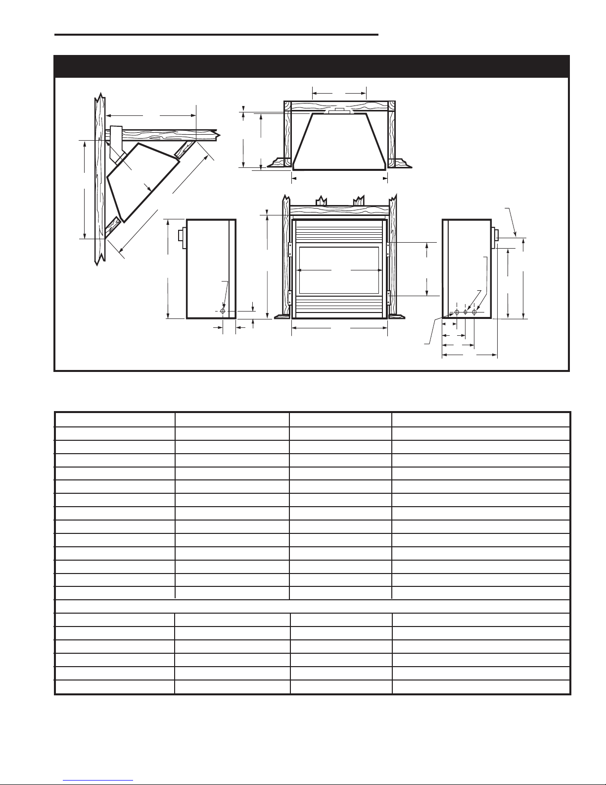
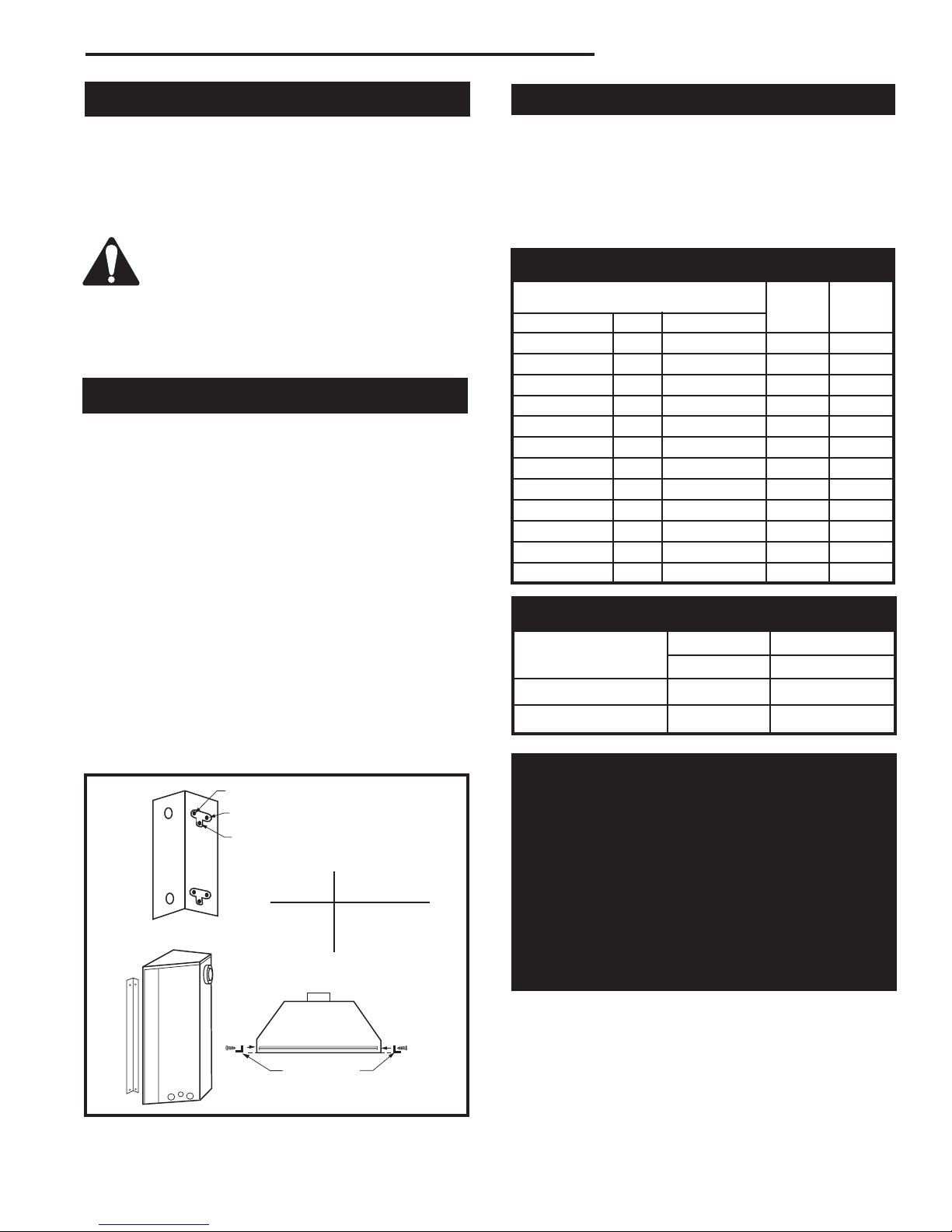
Fireplace Dimensions
7628
Fig. 1 Fireplace specifications and framing dimensions.
Ref. 33RDVN 36RDVN 39RDVN
A 33” (838 mm) 36” (914 mm) 39” (991 mm)
B 28
⁷⁄₈” (733 mm) 34¹⁄₄” (870 mm) 34¹⁄₄” (870 mm)
C 31” (787 mm) 33” (838 mm) 36” (914 mm)
D 16
³⁄₈” (416 mm) 21” (533 mm) 21” (533 mm)
E 22” (559 mm) 24” (610 mm) 24” (610 mm)
F 11
G 14
H 20
I 23
J 5” (127 mm) 6
K 7
L 8
M 1
Framing Dimensions
N 29” (737 mm) 35” (889 mm) 35” (889 mm)
O 33
P 12” (305 mm) 16
Q 51” (1295 mm) 58
R 25
S 36” (914 mm) 41
¹⁄₂” (292 mm) 16” (406 mm) 16” (406 mm)
³⁄₄” (375 mm) 19” (483 mm) 19” (483 mm)
¹⁄₄” (515 mm) 23⁷⁄₈” (606 mm) 23⁷⁄₈” (606 mm)
³⁄₄” (603 mm) 27¹⁄₂” (699 mm) 27³⁄₈” (695 mm)
³⁄₄” (171 mm) 6¹⁄₄” (159 mm)
¹⁄₂” (191 mm) 10” (254 mm) 8³⁄₈” (213 mm)
¹⁄₂” (216 mm) 13¹⁄₂” (343 mm) 12¹⁄₂” (318 mm)
⁷⁄₈” (18 mm) 1⁷⁄₈” (18 mm) 1⁷⁄₈” (18 mm)
¹⁄₂” (851 mm) 36¹⁄₂” (927 mm) 39¹⁄₂” (1003 mm)
¹⁄₂” (419 mm) 16¹⁄₂” (419 mm)
⁷⁄₈“ (1495 mm) 62¹⁄₄” (1581 mm)
¹⁄₂” (648 mm) 29⁷⁄₈” (748 mm) 31¹⁄₈” (790 mm)
⁵⁄₈” (1057 mm) 44” (1118 mm)
20007628
5
RDVN Series Direct Vent Gas Fireplace
Y
E
A
B
C
D
F
Y
B
X
X
A B C D E
V
W
X
Y
Z
Fireplace
J
F
G
H
I
Mantel
Leg
O
N
M
L
K
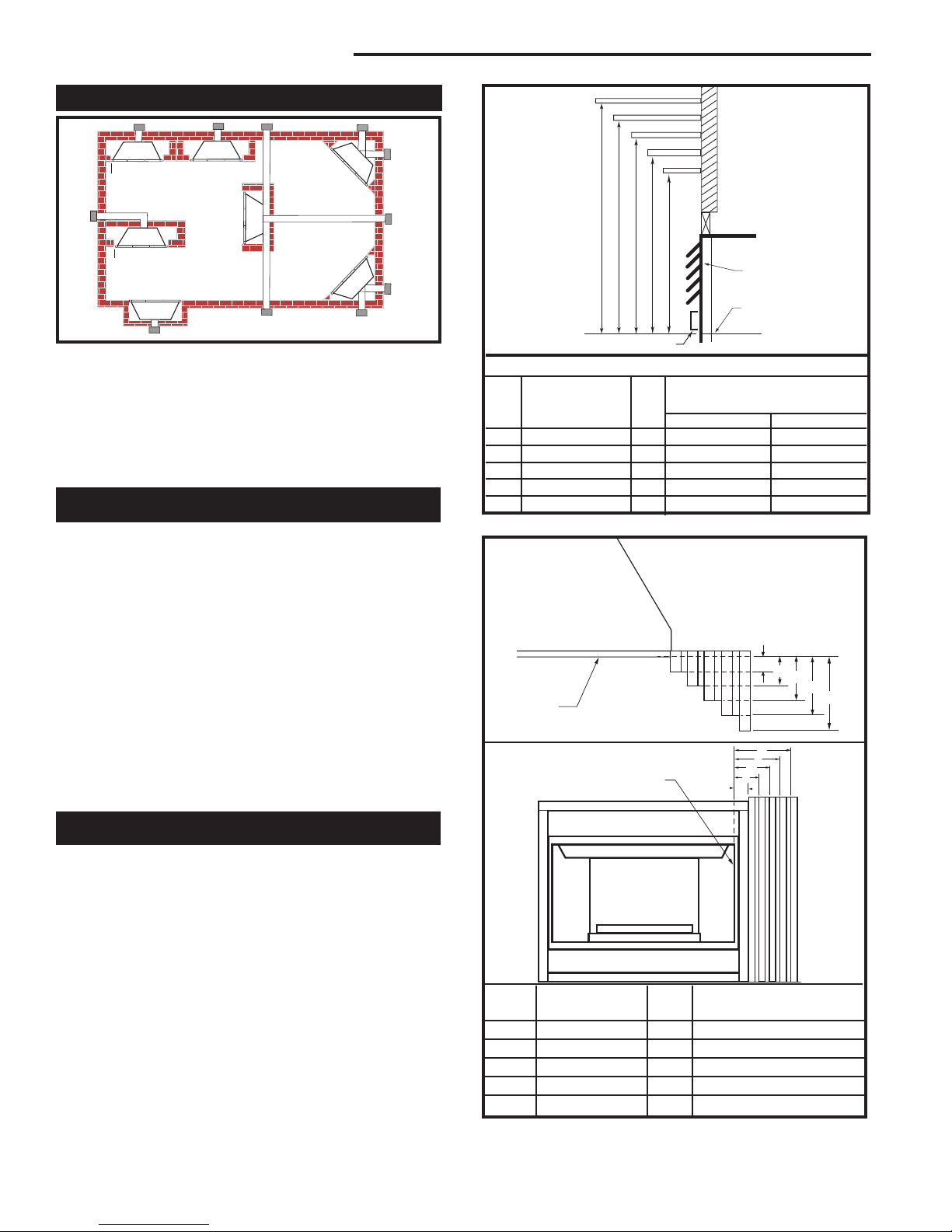
Locating Your Fireplace
LU584-T
Fig. 2 Locate gas fireplace.
A - Flat on wall B - Cross corner C - **Island
D - Room divider E - Flat on wall corner F - Chase installation
Y - Refer to “Clearance to Combustibles” Section
Note (Fig. 2):
** Island (C) and Room Divider (D) installation is possible as
long as the horizontal portion of the vent system (X) does not
exceed 20’ (6m). See details in manual Venting Section.
Clearance to Combustibles
Top of Unit to Ceiling ............................... 36” (914 mm)
Front of Unit to Combustibles .................. 36” (914 mm)
Appliance
Top .......................................................... 0” (0 mm)
Bottom ..................................................... 0” (0 mm)
Side ......................................................... 0” (0 mm)
Back ........................................................ 0” (0 mm)
Venting
Concentric sections of DV Vent
Top, bottom & sides .............................. 1” (25 mm)
Rear Vent Applications
Top ........................................................ 2” (51 mm)
Sides and Bottom .................................. 1” (25 mm)
Flex Vent .................................................. 7/8” (22 mm)
Top Louvre
Assembly
Top of Combustion
Chamber
Bottom of Door Trim
CFM146
Mantel Chart
Mantel Shelf Mantel from Top
Ref. or Breast Plate Ref. of Combustion Chamber
Depth 36/39/RDVN 33RDVN
V 10” (254 mm) A 19” (483 mm) 17” (432 mm)
W 8” (203 mm) B 17” (432 mm) 15” (381 mm)
X 6” (152 mm) C 15” (381 mm) 13” (330 mm)
Y 4” (101 mm) D 13” (330 mm) 11” (279 mm)
Z 2” (50 mm) E 11” (279 mm) 9” (229 mm)
Fig. 3a Combustible mantel minimum installation.
Black
Surround
Face
Side of
Combustion Chamber
Mantels
The height that a combustible mantel is fitted above the
fireplace is dependent on the depth of the mantel. This
also applies to the distance between the mantel leg (if
fitted) and the fireplace.
For the correct mounting height and widths refer to
Figures 3a and 3b.
The fitting of a bay window trim kit does not effect
the distances and reference points referred to in the
diagram and chart.
Noncombustible mantels and legs may be installed at
any height and width around the appliance.
When using paint or lacquer to finish the mantel, such
paint or lacquer must be heat resistant to prevent
discoloration.
6
CFM170
Mantel Mantel Leg from Side
Ref. Leg Depth Ref. of Comb. Opening
F 10” (254 mm) K 11¹⁄₂” (292 mm)
G 8” (203 mm) L 9¹⁄₂” (241 mm)
H 6” (152 mm) M 7¹⁄₂” (191 mm)
I 4” (101 mm) N 5¹⁄₂” (140 mm)
J 2” (51 mm) O 3¹⁄₂” (89 mm)
Fig. 3b Combustible mantel leg minimum installation.
20007628
RDVN Series Direct Vent Gas Fireplace
C
A
B
Hearth
A hearth is not mandatory but is recommended for
aesthetic purposes. We recommend a noncombustible
hearth which projects out 12” (305 mm) or more from
the front of the fireplace.
Cold climate installation recommendation:
When installing this unit against a
non-insulated exterior wall or chase,
it is mandatory that the outer walls
be insulated to conform to applicable
insulation codes.
NOTE: Never allow vapor barrier to contact the
outer casing of this fireplace or venting.
Framing and Finishing
1. Choose the unit location.
2. Place the unit into position and secure it to the floor
with 1¹⁄₂” (38 mm) screws, or nails. The holes to
secure the unit to the floor are located just behind
the access door grille on the left and right side of the
unit.
3. Frame in the fireplace with a header across the top.
It is important to allow for the finished wall face when
setting the depth of the frame.
4. Attach the fireplace to the frame using the adjust
able frame drywall strips (located behind the access
door for shipping). Preset the depth to suit the facing
material of the wall. The strips are adjustable to 1/2”
(13 mm), 5/8” (16 mm) or 3/4” (19 mm). (Fig. 4)
5. Screw through the slotted holes in the drywall strip
and into the pre-drilled holes in the fireplace side.
Measure from the face of the fireplace to the face of
the drywall strip to confirm the final depth.
-
Final Finishing
Noncombustible materials such as brick or tile may be
extended over the edges of the face of the appliance.
DO NOT cover any vent or grille panels.
If a Trim Kit is going to be installed on the fireplace, the
brick or tile will have to be installed flush with the edges
of the appliance.
Gas Specifications
Max. Min.
Input Input
Model Fuel Gas Control BTU/h BTU/h
33RDVN Nat Millivolt 18,000 13,000
33RDVP Prop Millivolt 18,000 13,000
33RDVDSN Nat 120 V 18,000 n/a
33RDVDSP Prop 120 V 18,000 n/a
36RDVN Nat Millivolt 20,000 13,000
36RDVP Prop Millivolt 20,000 13,000
36RDVDSN Nat 120 V 20,000 n/a
36RDVDSP Prop 120 V 20,000 n/a
39RDVN Nat Millivolt 22,000 15,000
39RDVP Prop Millivolt 22,000 15,000
39RDVDSN Nat 120 V 22,000 n/a
39RDVDSP Prop 120 V 22,000 n/a
Gas Inlet and Manifold Pressures
Natural LP (Propane)
Inlet Minimum 4.5” w.c. 10.8” w.c.
Inlet Maximum 14.0” w.c. 14.0” w.c.
Manifold Pressure 3.5” w.c. 10.0” w.c.
High Elevations
Adjustable Drywall Strip
(Nailing Flange)
Screw Drywall
Position Depths
Fig. 4 Nailing flanges.
A 1/2” / 13mm
B 5/8” / 16mm
C 3/4” / 19mm
Adjustable
1/2”, 5/8” &
3/4” Spacing
20007628
Input ratings are shown in BTU per hour and are
certified without deration for elevations up to
4,500 feet (1,370 m) above sea level.
For elevations above 4,500 feet (1,370 m) in USA,
installations must be in accordance with the current ANSI Z223.1/NFPA 54 and/or local codes having jurisdiction.
In Canada, please consult provincial and/or local
authorities having jurisdiction for installations at
elevations above 4,500 feet (1,370 m).
FP1023
7
RDVN Series Direct Vent Gas Fireplace
Gas Line Installation
When purging gas line, the front window
frame assembly must be removed.
1. The gas pipeline can be brought in through the rear
of the fireplace as well as the bottom. Knockouts are
provided on the bottom behind the valve to allow for
the gas pipe installation and testing of any gas connection. It is most convenient to bring the gas line in
from the rear right side of the valve as this allows fan
installation or removal without disconnecting the gas
line.
The gas line connection can be made with properly
tinned 3/8” copper tubing, 3/8” rigid pipe or an approved flex connector. Since some municipalities
have additional local codes, it is always best to con
sult your local authority and the National Fuel Gas
Code, ANSI Z223.1/NFPA 54 in the USA or the CSAB149.1 installation codes.
*Adhere to the following installation requirements in the State
of Massachusetts:
• The installer must be a licensed plumber or gas fitter.
• Flex connectors must be Massachusetts approved, cannot
exceed 36” (914mm) in length, must be a minimum 1/2”
dia. and may not penetrate a wall.
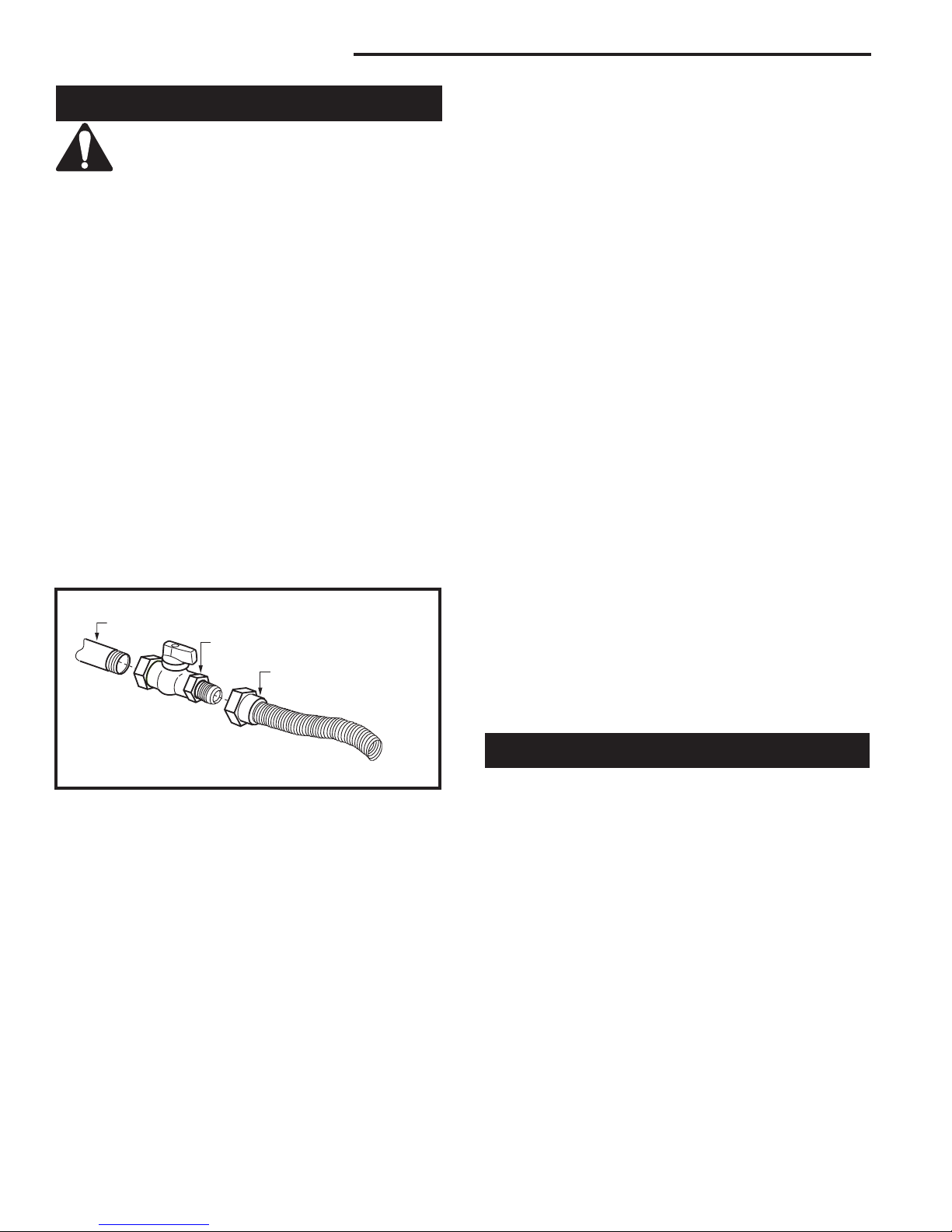
1/2” Gas Supply
1/2” NPT X 1/2” Flare Shut-off Valve
3/8” Flex line
(from valve)
5. For natural gas, a minimum of 3/8” iron pipe with a
gas supply pressure of 4.5” w.c. (from the gas meter). Consult with local gas utility and ANSI Z223.1/
NFPA 54 if any questions arise concerning pipe
sizes.
6. Turn the gas supply to ‘ON’ and check for leaks. DO
NOT USE OPEN FLAME FOR THIS PURPOSE.
Use an approved leak testing solution.
7. The appliance and its appliance main gas valve
must be disconnected from the gas supply piping
system during any pressure testing of that system at
test pressures in excess of 1/2 psig (3.5KPa).
8. This appliance must be isolated from the gas supply
piping system by closing its equipment shut off valve
during any pressure testing of the gas supply piping
system at test pressures equal to 1/2 psig (3.5KPa).
Always check for gas leaks with a mild soap and
water solution. Do not use an open flame for leak
testing.
The gas control is equipped with a captured screw type
pressure test point, therefore it is not necessary to provide a 1/8” test point up stream of the control.
When using copper or flex connector use only approved
fittings. Always provide a union when using black iron
pipe so that the gas line can be easily disconnected for
burner or fan servicing. Refer to the gas specifications
for pressure details and ratings.
The fireplace valve must not be subjected to any test
pressures exceeding 1/2 psi. Isolate or disconnect this
or any other gas appliance control from the gas line
when pressure testing.
FP297A
Fig. 5 Typical gas supply installation.
2. The gas control inlet is 3/8” NPT typical installation
layout for rigid pipe is shown in Figure 5.
NOTE: All models are equipped with a flex tube
with a shut off valve having a 1/2” NPT inlet. The
flex line with shut off is shipped in the control
valve compartment. Using two wrenches, tighten
the flexible tube at the shut off valve and at the
gas control
3. When using a flex connector,* use only approved fit
tings. When a union is installed, provide easy access
in its placement for servicing. Refer to gas specification for pressure details and ratings.
4. When a vertical section of gas pipe is required for
the installation, a condensation trap is needed. In
Canada see CSA-B149.1 for code details. See the
National Fuel Gas Code ANSI Z223.1/NFPA 54 in
the USA.
8
Remote ON/OFF Switch
Installation:
1. Thread the wiring through holes on the end panels
of appliance. Take care not to cut wire or insulation
on metal edges. Route the wire to a conveniently
located receptacle box.
2. Attach the wire to the ON/OFF switch and install the
switch into the receptacle box.
3. Connect the other ends of the wire to the gas control
valve. (Fig. 6)
-
20007628
RDVN Series Direct Vent Gas Fireplace
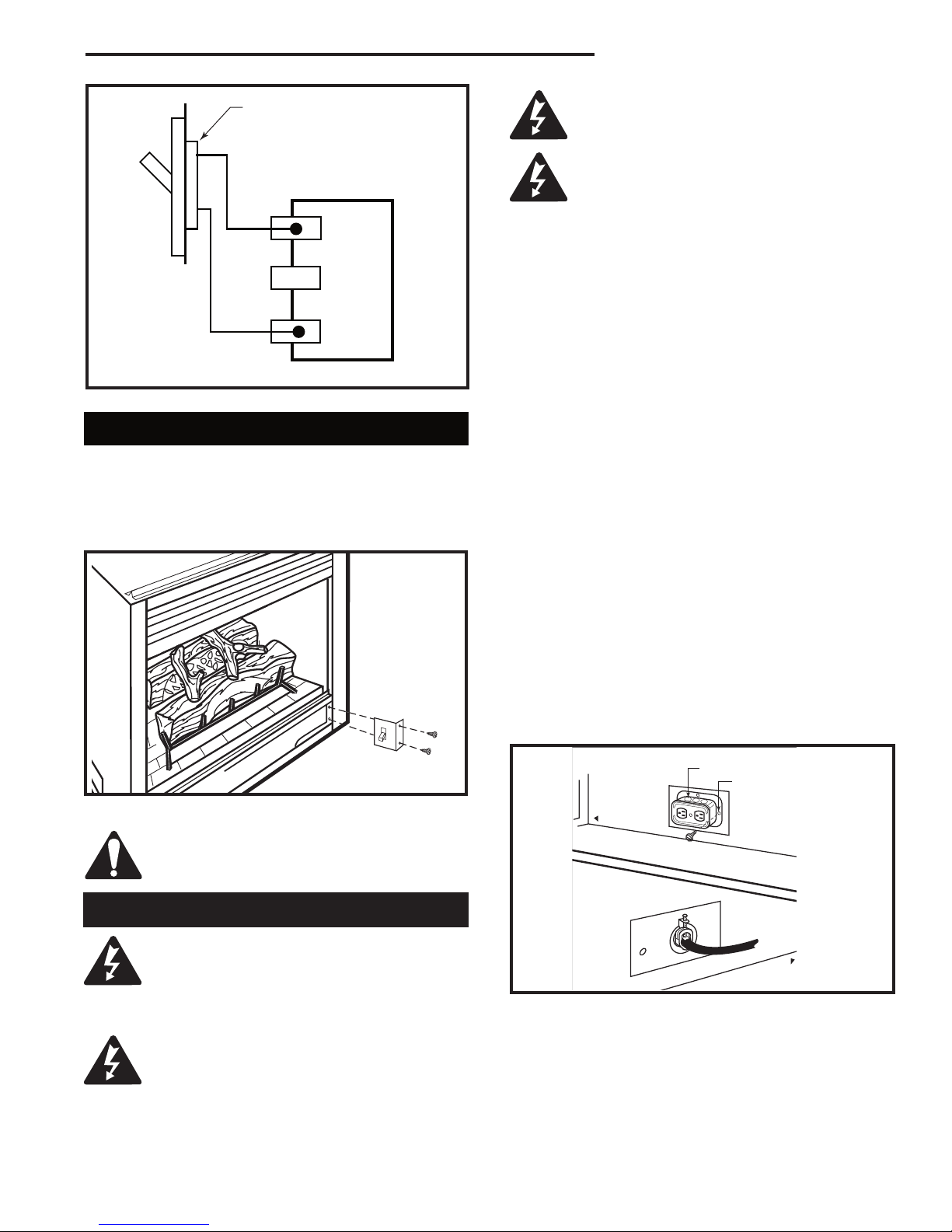
OUTSIDE
FRONT OF UNIT
INSIDE
FRONT OF UNIT
TP
TH
TP
TH
Remote ON/OFF
Switch or Thermostat or
Remote Control
Gas
Control
Valve
FP1224
Fig. 6 Remote switch wiring diagram.
Alternate Switch Location
The remote switch can be installed on the front/side of
the access door. Simply mount the switch to the bracket
provided and screw the bracket to either side of the
frame, lining up the screws with the pre-punched holes.
(Fig. 7)
It is strongly suggested that the wiring of
the EB-1 Electrical Junction Box be carried
out by a licensed electrician.
Ensure that the power to the supply line
has been disconnected before commencing this procedure.
The EB-1 Electrical junction box has been fitted standard on this model to allow for the easy connection of an
optional fan kit.
To connect the EB-1 box to the house electrical supply
follow the steps below.
1. Unscrew retaining screw from EB-1 base plate (Fig.
8) and remove the EB-1 assembly from the appliance.
2. Remove the front cover of the EB box.
3. Remove the plug socket assembly from the EB-1
box.
4. Feed the supply line in through the EB-1 opening in
the side of the appliance and then through the back
of the EB-1 assembly. (Fig. 8)
5. Connect the black wire of the power supply line to
the brass screw (polarized) of the socket assembly.
6. Connect the white wire of the power line to the
chrome screw of the socket assembly.
7. Connect the ground wire of the supply line to the
green screw of the socket assembly.
8. Refit the socket assembly back into the electrical
box and replace the cover plate. Secure the cable
with the clamp on the outside of the EB-1 base
plate and refit the EB-1 assembly to the unit with the
screw removed in step 1.
Fig. 7 Alternate switch location.
Do not wire the remote ON/OFF wall
switch for the gas fireplace to the 120 volt
power supply.
EB-1 Electrical Box
The fireplace, when installed, must be
electrically connected and grounded in
accordance with local codes or, in the ab-
20007628
sence of local codes, with the current CSA
C22.1 Canadian Electrical Code.
For USA installations follow local codes
and the national electrical code ANSI/
NFPA No. 70.
T256
Electrical Box
Retaining Screw
FP580
Fig. 8 EB-1 receptacle.
9

RDVN Series Direct Vent Gas Fireplace
General Venting
Your fireplace is approved to be vented either through
the side wall, or vertical through the roof.
• Only CFM Corporation venting components specifically approved and labelled for this fireplace
may be used.
• Venting terminals shall not be recessed into a wall or
siding.
• Horizontal venting which incorporates the twist lock
pipe must be installed on a level plane without an
inclining or declining slope.
• Horizontal venting which incorporates the use of flex
venting shall have an inclining slope from the unit of
1” (25 mm) per 24” (610 mm).
There must not be any obstruction such as bushes,
garden sheds, fences, decks or utility buildings within
24” from the front of the termination hood.
Do not locate termination hood where excessive snow
or ice build up may occur. Be sure to check vent termination area after snow falls, and clear to prevent accidental blockage of venting system. When using snow
blowers, make sure snow is not directed towards vent
termination area.
Location of Vent Termination
It is imperative the vent termination be located observing the minimum clearances as shown on the following
page.
10
20007628
RDVN Series Direct Vent Gas Fireplace
V
V
V
V
V
V
V
X
X
X
D
E
B
B
B
C
B
M
B
A
J
K
F
L
VENT TERMINATION AIR SUPPLY INLET
AREA WHERE TERMINAL IS NOT PERMITTED
H
I
Operable
Operable
Fixed
Closed
V
B
INSIDE
CORNER DETAIL
V
A
G
N
N
CFM145a
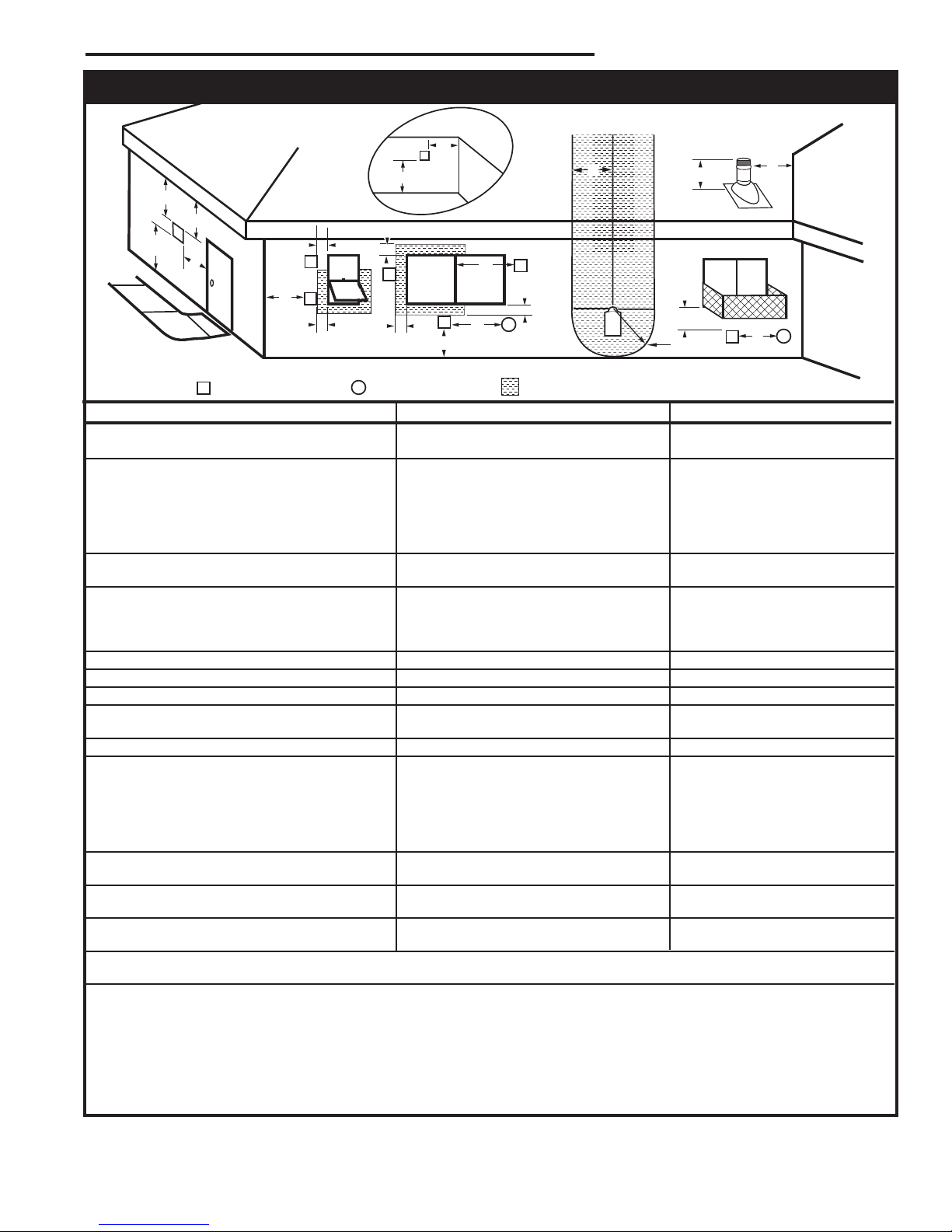
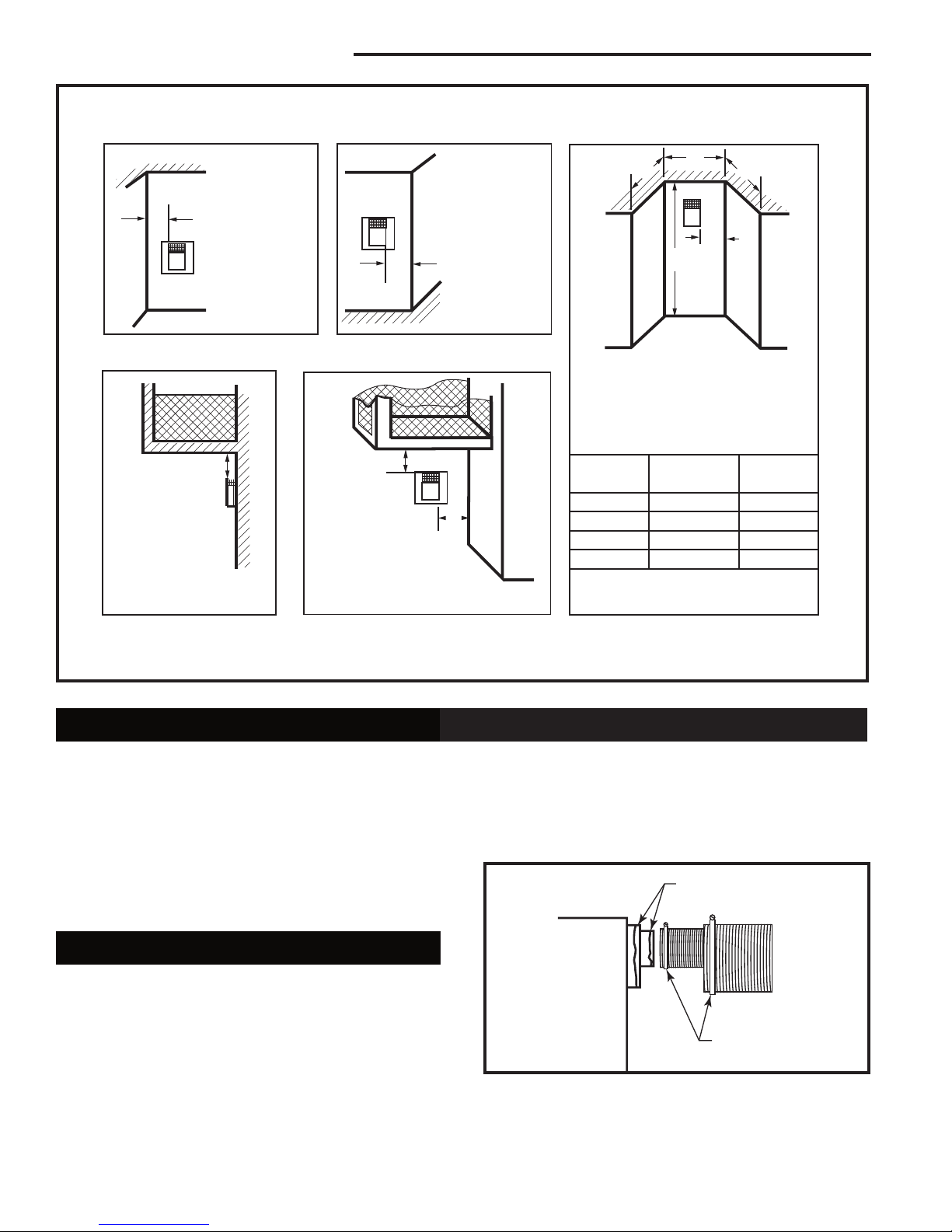
General Venting Information - Termination Location
Canadian Installations1 US Installations
A = Clearance above grade, veranda, porch, 12” (30cm) 12” (30cm)
deck, or balcony
B = Clearance to window or door that may be 6” (15cm) for appliances 6” (15cm) for appliances
opened < 10,000Btuh (3kW), 12” (30cm) < 10,000 Btuh (3kW), 9”
for appliances > 10,000 Btuh (3kW) and (23cm) for appliances > 10,000
< 100,000 Btuh (30kW), 36” (91cm) Btuh (3kW) and < 50,000 Btuh
for appliances > 100,000 Btuh (30kW) (15kW), 12” (30cm) for
appliances > 50,000 Btuh (15kW)
C = Clearance to permanently closed window 12” (305mm) recommended to 12” (305mm) recommended to
prevent window condensation prevent window condensation
D = Vertical clearance to ventilated soffit located
above the terminal within a horizontal 18” (458mm) 18” (458mm)
distance of 2 feet (610mm) from the center
line of the terminal
E = Clearance to unventilated soffit 12” (305mm) 12” (305mm)
F = Clearance to outside corner see next page see next page
G = Clearance to inside corner (see next page) see next page see next page
H = Clearance to each inside of center line 3’ (91cm) within a height of 15’ 3’ (91cm) within a height of 15’
extended above meter/regulator assembly above the meter/regulator assembly above the meter/regulator assy
I = Clearance to service regulator vent outlet 3’ (91cm) 3’ (91cm)
J = Clearance to nonmechanical air supply inlet 6” (15cm) for appliances < 10,000 6” (15cm) for appliances
to building or the combustion air inlet to any Btuh (3kW), 12” (30cm) for < 10,000 Btuh (3kW), 9”
other appliances appliances > 10,000 Btuh (3kW) and < (23cm) for appliances > 10,000
100,000 Btuh (30kW), 36” (91cm) Btuh (3kW) and < 50,000 Btuh
for appliances > 100,000 Btuh (30kW) (15kW), 12” (30cm) for
appliances > 50,000 Btuh (15kW)
K = Clearance to a mechanical air supply inlet 6’ (1.83m) 3’ (91cm) above if within 10’
(3m) horizontally
L = Clearance above paved sidewalk or paved 7’ (2.13m)† 7’ (2.13m)†
driveway located on public property
M = Clearance under veranda, porch, deck or 12” (30cm)‡ 12” (30cm)‡
balcony
N = Clearance above a roof shall extend a minimum of 24” (610mm) above the highest point when it passes through the roof
surface, and any other obstruction within a horizontal distance of 18” (450mm).
1 In accordance with the current CSA-B149 Installation Codes
2 In accordance with the current ANSI Z223.1/NFPA 54 National Fuel Gas Codes
† A vent shall not terminate directly above a sidewalk or paved driveway which is located between two single family dwellings and serves both dwell ings
‡ only permitted if veranda, porch, deck or balcony is fully open on a minimum 2 sides beneath the floor:
NOTE: 1. Local codes or regulations may require different clearances.
2. The special venting system used on Direct Vent Fireplaces are certified as part of the appliance, with clearances tested and approved by the
listing agency.
3. CFM Corporation assumes no responsibility for the improper performance of the appliance when the venting system does not
meet these requirements.
Fig. 9 Vent termination clearances.
20007628
2
11
RDVN Series Direct Vent Gas Fireplace
Outside Corner
Inside Corner
Termination Clearances
Termination clearances for buildings with combustible and noncombustible exteriors.
G =
Combustible
6" (152 mm)
Noncombustible
2" (51 mm)
F =
Combustible
6" (152 mm)
Noncombustible
2" (51 mm)
G
Balcony with no side wall
M =
Combustible &
Noncombustible
12" (305 mm)
M
Balcony with perpendicular side wall
M = 24" (610 mm)
P = 20” (508 mm)
M
F
Alcove Applications*
C
D
C
E
V
V
Combustible &
Noncombustible
V
V
V
E = Min. 6” (152 mm) for
non-vinyl sidewalls
Min. 12” (305 mm) for
vinyl sidewalls
O = 8’ (2.4 m) Min.
O
P
*NOTE: Termination in an alcove space (spaces open only on one side and with an overhang) is permitted with the dimensions
specified for vinyl or non-vinyl siding and soffits. 1. There must be a 3’ (914 mm) minimum between termination caps. 2. All
mechanical air intakes within 10’ (1 m) of a termination cap must be a minimum of 3’ (914 mm) below the termination cap. 3. All
gravity air intakes within 3’ (914 mm) of a termination cap must be a minimum of 1’ (305 mm) below the termination cap.
Fig. 9 Termination clearances.
Canadian Installations:
The venting system must be installed in accordance
with the current CSA-B149 .1 installation code.
USA Installations:
The venting system must conform with local codes and/
or the current National Fuel Gas code ANSI Z223.1/
NFPA 54.
General Information on Assembling Vent Pipes
* Be sure the vent is actually crushed before proceeding. Apply a tug to be sure the vent will not slip off the
collars.
Repeat process with 7” flex vent pipe. The same procedure must be performed on the vent side.
Only venting components manufactured by CFM Corporation can be used in Direct Vent systems.
Flex Vent Pipes
Before joining the flex vent pipe to the unit, apply a
bead of high temperature sealant* (provided) to the 4”
pipe exiting the fireplace. Secure flex vent pipe in place
with a hose clamp (provided).
*Be sure the flex pipe overlaps at least 1” (25 mm) onto
the collars of the fireplace and termination. If the termination has an internal bead, be sure to overlap and
secure 1” (25 mm) past the bead.
12
Fig. 10 Apply high temperature sealant to 4” and 7” pipes.
No.
of Caps D
1 3’ (914 mm) 2 x D
2 6’ (1.8 m) 1 x D
3 9’ (2.7 m) 2/3 x D
4 12’ (3.7 m) 1/2 x D
D
= # of Termination caps x 3
Min.
C
= (2 / # termination caps) x D
Max.
Min.
Hose Clamp
C
Apply High Temperature
Sealant
Max.
Actual
Actual
Actual
Actual
Actual
584-15
FP1471
20007628
Twist Lock Pipes
3
4
5
6
7
8
9
10
11
12
13
14
15
16
17
18
19
20
21
22
23
24
25
26
27
28
29
30
3 4 5 6 7 8 9 10 11 12 13 14 15 16 17 18 19 20
eg: A
eg: B
When using CFM Corporation twist-lock pipe it is not
necessary to use sealant on the joints. The only areas
of the venting system that need to be sealed with high
temperature silicone sealant are the collars on the
fireplace and termination, and the sliding joint of any
telescopic vent section used in the system.
To join the twist lock pipes together, simply align the
beads of the male end with the grooves of the female
end, then while bringing the ends together, twist the
pipe until the flange on the female end contacts the
external flange on the male end. It is recommended that
you secure the joints with three (3) sheet metal screws,
however this is not mandatory with twist lock pipe.
To make it easier to assemble the joints we suggest
putting a lubricant (Vaseline or similar) on the male end
of the twist lock pipe prior to assembly.
RDVN Series Direct Vent Gas Fireplace
Vertical dimension from the floor of the fireplace to
the center of the horizontal vent pipe
Male End
Screw Holes
Fig. 11 Twist-lock pipe joints.
Female End
TWL100
Horizontal dimension from the outside face of the wall to
the center of the fireplace vent flange
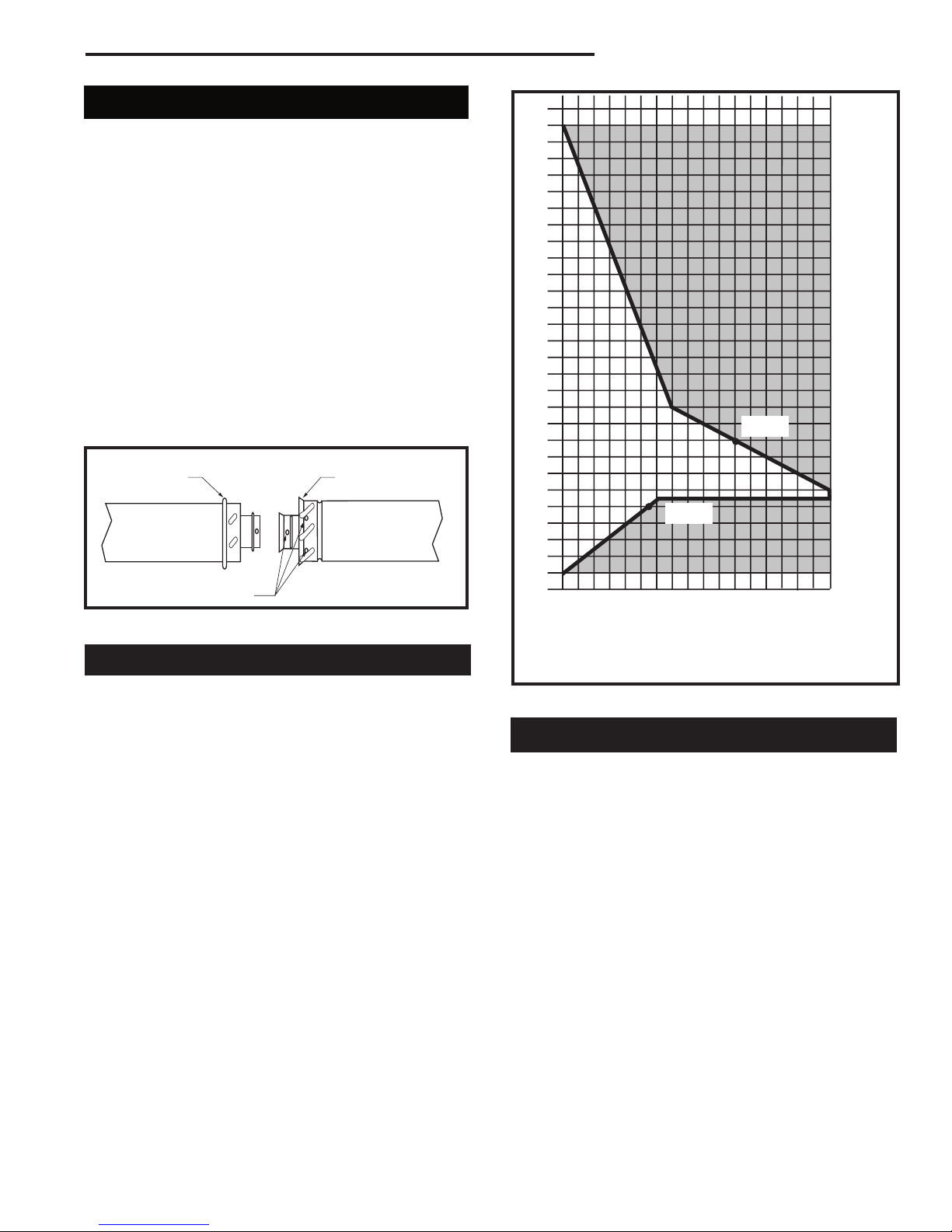
How to Use the Vent Graph
The vent chart should be read in conjunction with the
Sidewall vent graph showing the relationship between vertical
and horizontal dimensions for a Direct Vent flue system.
Fig. 12 Sidewall venting graph. (Dimensions in feet)
following vent installation instructions to determine the
relationship of the vertical and horizontal dimensions of
the vent system.
1. Determine the height of the center of the horizontal
vent pipe exiting through the outer wall. Using this
dimension on the Sidewall Vent Graph (Fig. 12),
locate the point intersecting with the slanted graph
line.
2. From the point of this intersection, draw a vertical
line to the bottom of the graph.
3. Select the indicated dimension, and position the
fireplace in accordance with same.
Example A:
If the vertical dimension from the floor of the fireplace
is 11’ (3.4 m) the horizontal run to the face of the outer
wall must not exceed 14’ (4.3 m).
Example B:
If the vertical dimension from the floor of the unit is 7’
(2.14 m), the horizontal run to the face of the outer wall
must not exceed 8¹⁄₂’ (2.6 m).
20007628
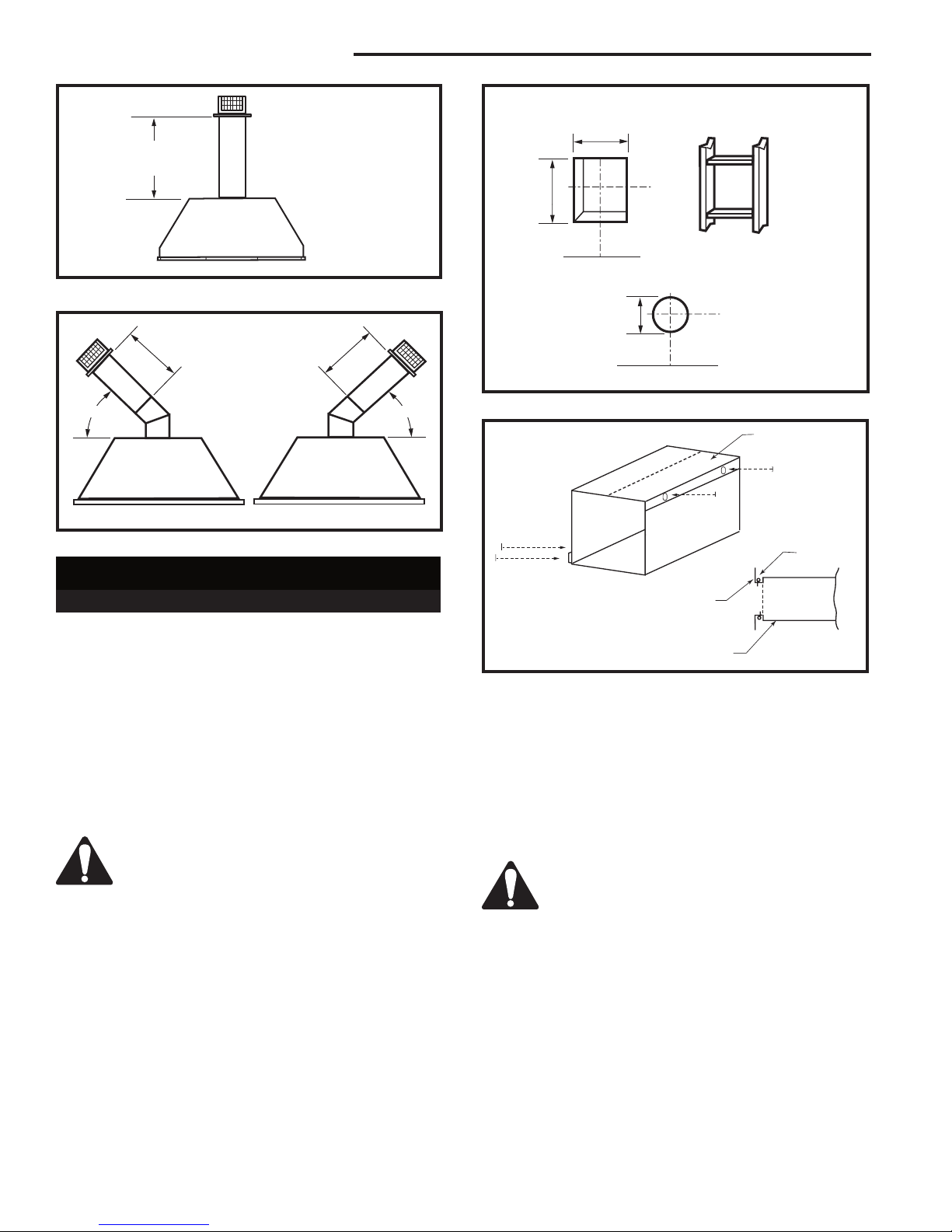
Rear Wall Vent Application
When installed as a rear vent unit this appliance may be
vented directly to a termination located on the rear wall
behind the appliance.
• Only CFM Corporation venting components are
approved to be used in these applications (See
‘Venting Components’ listed for different installation
requirements).
• The maximum horizontal distance between the rear
of the appliance (or end of the transition elbow in a
corner application) and the outside face of the rear
wall is 20” (508 mm). (Fig. 13, 14)
• Only one 45° elbow is allowed in these installations.
• Minimum clearances between vent pipe and com-
bustible materials are as follows:
Top - 2” (51 mm)
Sides - 1” (25 mm)
Bottom - 1” (25 mm)
13
RDVN Series Direct Vent Gas Fireplace
20 "
(5 0 8 m m )
Ma x .
20 "
(5 0 8 m m )
Ma x .
20” (508 mm)
Max.
Rear Vent Top View
10³⁄₈"
(265 mm)
Vent Opening for Combustible Wall
9³⁄₈"
(240 mm)
Framing
Detail
DVR584-600
Fig. 13 Rear vent application, no elbows.
45°
Rear Vent Top View, Corner Installation
Fig. 14 Rear vent application, one 45° elbow.
45°
FP836
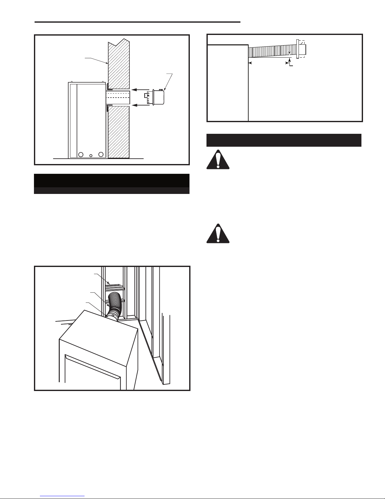
Rear Wall Vent Installation
Twist Lock Pipe
Step 1
Locate and cut the vent opening in the wall. For combustible walls first frame in opening. (Fig. 15)
NOTE: When using flex vent, the opening will have to
be measured according to the 1/2” (13 mm) rise in 12”
(305 mm) vertical run.
Combustible Walls:
Cut a 10³⁄₈”H x 9³⁄₈” W (265 x 240
mm) hole through the exterior wall and frame as shown.
(Fig. 15)
Noncombustible Walls:
Hole opening should be 7¹⁄₂”
(191mm) diameter.
Zero clearance sleeve is only required for
combustible walls.
Step 2
Measure wall thickness and cut zero clearance sleeve
parts to proper length (Maximum 12” / 305 mm). Assemble sleeve to its maximum opening (10³⁄₈” x 9³₈”)
and attach to firestop assembly. (Fig. 16)
Step 3
Measure the horizontal length requirement for the venting including a 2” (51 mm) overlap, i.e. from the elbow
to the outside wall face plus 2” (51 mm). (Fig. 14)
Fireplace Hearth
Opening for Noncombustible Wall
7¹⁄₂" Dia.
(190 mm)
Fireplace Hearth
Fig. 15 Locate vent opening on wall.
Adjustable Zero Clear-
ance Sleeve
#8 Screws (2)
Adjustable Zero Clearance Sleeve
Fig. 16 Adjustable zero clearance sleeve.
Rnd.
Firestop
VO584-100
Max. Length 12”
(305mm)
#8 Screws (2)
#8 Screws
(2)
ZCS101
Step 4
Install the 4” (102 mm) vent to the appliance collar and
secure with 3 sheet metal screws. Install the 7” (178
mm) vent pipe to the appliance collar and secure with 3
sheet metal screws. It is not necessary to seal this connection. If a 45° elbow is being used attach the elbow
to the appliance in the same manner then attach the
venting to the elbow.
It is critical that there is no downward
slope away from the appliance when connecting the vent or elbow.
Step 5
Guide the venting through the vent hole as you place
the appliance in its installed position. Guide the 4” (102
mm) and 7” (178 mm) collar of the vent termination into
the outer ends of the venting. Do not force the termination. If the vent pipes do not align with the termination,
remove and realign the venting at the appliance flue
collars. (Fig. 17) Attach the termination to the wall as
outlined in the instruction sheet supplied with the termination.
14
20007628
Finished
1" (25mm)
24" (610mm)
Wall
Vent
Termination
RDVN Series Direct Vent Gas Fireplace
(Minimum 1” (25mm) rise)
FP1472
Fig. 19 There must be a 1” rise in 24” length.
Vertical Sidewall Applications
FP1005
Fig. 17 Side view of final unit location.
Rear Wall Vent Installation -
Flex Vent Pipe
Follow Steps 1 and 2 on Page 13.
Step 3
Install the 4” (102 mm) flex vent pipe to the appliance
collars described in “General Information Assembling
Vent Pipes”, Page 12. If the installation requires a 45°
angle, grasp the vent pipe close to the appliance collar
and bend to 45°. DO NOT exceed 45°. (Fig. 18)
Install the 7” vent pipe in the same manner as Step 2.
Termination
Flex Section
Appliance Collars
Since it is very important that the venting system maintain its balance between
the combustion air intake and the flue
gas exhaust, certain limitations as to vent
configurations apply and must be strictly
adhered to.
The Vent Graph shows the relationship between vertical and horizontal side wall venting and will help to
determine the various dimensions allowable.
Minimum clearance between vent pipes
and combustible materials is 1”(25 mm)
on top, bottom and sides unless otherwise
noted.
When vent termination exits through foundations less
than 20” (508 mm ) below siding outcrop, the vent pipe
must flush up with the siding. It is always best to locate
the fireplace in such a way that minimizes the number
of offsets and horizontal vent length.
The horizontal vent run refers to the total length of vent
pipe from the flue collar of the fireplace to the face of
the outer wall.
Horizontal plane means no vertical rise exists on this
portion of the vent assembly.
Fig. 18 Grasp the vent pipe close to the collar and bend to
45° angle. Do not exceed 45°.
NOTE: There must be a 1” (25 mm) rise in a 24” (610
mm) length of flex vent.
Step 4
Assemble the flex vent to the collars on the termination
as you did on the appliance.
20007628
FP1473
• The maximum horizontal vent run is 20 ft. (6.1 m)
when the vertical vent rise is 7¹⁄₂ ft. (2.3 m). (Fig. 20)
• The maximum number of 90° elbows per side wall
installation is three (3).
• If a 90° elbow is used in the horizontal vent run
(level height maintained) the maximum horizontal
vent length is reduced by 36” (914 mm). (Fig. 21)
This does not apply if the 90° elbows are used to
increase or redirect a vertical rise. (Fig. 22)
Example: According to the chart the maximum horizontal vent length in a system with a 7.5’ (2.3 m) vertical rise is 20’ (6 m) and if a 90° elbow is required in
the horizontal vent it must be reduced to 17’ (5.2 m).
In Figure 21 Dimension A plus B must not be greater
than 17’ (5.2 m).
15
 Loading...