

Tema Telecomunicazioni DIAL-112 Technical Installation Manual
TEMA TELECOMUNICAZIONI S.r.l.
Telecommunications - Electronics
DIAL-112
GSM Gateway Voice Interface
for ISDN BRI
TECHNICAL – INSTALLATION MANUAL
PRELIMINARY DOCUMENTATION
Version HW 1.0 - Version SW 1.11
Made in Italy by TEMA TELECOMUNICAZIONI S.r.l.
Recommendations
1. Use only original spare parts and consumables supplied by Tema Telecomunicazioni Srl for this equipment. The company shall
not be held responsible for any damage caused by the use of materials that they have not supplied.
2. The device has been carefully manufactured and tested. In any case, the product is not recommended for use in situations in
which incorrect operating may result in damage to persons and/or property.
3. We recommend that you carefully read all this manual before starting to use the device.
4. Do not expose the device to sunlight and protect it from sources of heat, dust, humidity and chemical agents.
5. This manual is the property of Tema Telecomunicazioni Srl and any duplication and reproduction, even partial, as well as
storage on any type of media is forbidden without written permission from Tema Telecomunicazioni Srl.
Revision Date Revision reason Prepared Checked/Approved
6 14/07/2010 Update GBC,MM FL
MAS-DIAL112-REV06EN Page 1 of 35
TEMA TELECOMUNICAZIONI SRL
La sottoscritta società : TEMA TELECOMUNICAZIONI SRL
con sede in : Via C. Girardengo, 1/4 - 20161 MILANO
dichiara che il prodotto:
Codici:
è stato costruito in conformità alle seguenti normative:
SICUREZZA EN 60950-1
EMC EN 55022
EN 55024
EN 61000-6-1
EN 61000-6-3
RADIO ETSI EN 301 511 V.9.0.2 Radio Spectrum - Global System for Mobile
TERMINALE DI TBR 3 - Integrated Services Digital Network (ISDN); Attachment
TELECOMUNICAZIONE requirements for terminal equipment to connect to an ISDN using
ISDN basic access.
Inoltre il prodotto sopra menzionato soddisfa i requisiti essenziali delle seguenti direttive:
• Direttiva LVD 73/23/EEC (Low Voltage Directive)
• Direttiva EMC 89/336/EEC – 92/31/ECC
• Direttiva 99/05/EC per apparati di Radio e Telecomunicazioni
MILANO, 11 Novembre 2008 TEMA TELECOMUNICAZIONI SRL
Duilio Pontillo
GSM Gateway Interface DIAL-112
DICHIARAZIONE DI CONFORMITÀ CE
DECLARATION OF CONFORMITY CE
Interfaccia GSM Gateway voce – GSM Gateway
DIAL-112 nelle versioni 1-2 SIM
Communications GSM900/1800
ETSI EN 300 607-1 Digital Cellular telecommunications system
ETSI EN 301 419-1, ETSI 300 342 Radio equipment and systems
EN 301 489-1 V1.6.1, EN 301 489-7 V1.3.1
MAS-DIAL112-REV06EN Page 2 of 35

TEMA TELECOMUNICAZIONI SRL
GSM Gateway Interface DIAL-112
I.
IMPORTANT INFORMATIONS REGARDING THE RECOVERY AND RECYCLING OF THIS
ELECTRONIC DEVICE
The crossed-out wheeled bin symbol below indicates that this electronic equipment is intended to be
disposed in a separate collection and not in an unsorted municipal waste, in order to provide for the
treatment of WEEE (Waste Electrical and Electronic Equipment) using best available recovery and recycling
techniques.
Specific treatment for WEEE is indispensable in order to avoid the dispersion of pollutants and other
hazardous substances into the waste stream, while recycling leads to reduction of disposal of waste and the
negative impacts on environment and human health. That is, priority is given to reuse of WEEE in its
components, subassemblies and consumables.
As the final holder, the user has an important role in contributing to reuse, recycling and other forms of
recovery of WEEE and is responsible to return this waste in the collection facilities set up by EC Member
Stases and to fulfill other duties in compliance with Directive 2002/96/EC and local laws.
MAS-DIAL112-REV06EN Page 3 of 35

TEMA TELECOMUNICAZIONI SRL
PAGE
GSM Gateway Interface DIAL-112
TABLE OF CONTENTS
1. INTRODUCTION OF GATEWAY DIAL-112.............................................................................. 6
2. CHARACTERISTICS OF DIAL-112 .......................................................................................... 7
3. PARTS COMPRISING THE SYSTEM (PACKING LIST).......................................................... 8
4. TECHNICAL SPECIFICATIONS ............................................................................................... 8
5. DESCRIPTION OF THE DEVICE .............................................................................................. 9
5.1. F
5.2. R
RONT VIEW
EAR VIEW
.............................................................................................................................................. 9
............................................................................................................................................... 9
6. INSTALLATION AND DIAGNOSTICS .................................................................................... 10
6.1. I
NSTALLATION OF THE
6.2. C
ONNECTION MODES
6.3. O
PERATIONAL AND DIAGNOSTIC INDICATORS
6.4. D
IAGNOSTICS
6.5. PC
CONNECTION
LEDS................................................................................................................................ 12
DIAL-112
UNIT
....................................................................................................... 10
............................................................................................................................... 10
.............................................................................................. 12
..................................................................................................................................... 13
7. SERVICES............................................................................................................................... 17
7.1. O
UTBOUND CALL GATEWAY
7.2. I
NBOUND CALL GATEWAY
7.3. T
ABLE OF NUMBERS AND PREFIXES
7.3.1. O
7.3.2. I
7.3.3. C
7.3.4. CLI
7.4. DISA
7.4.1. DISA
7.4.2. DISA
7.4.3. A
7.5. S
MART CALLBACK SERVICE
7.6. SMS
7.7. C
ALLBACK FOR THE INCOMING CALLS
7.8. A
LARM CONTACT DIALER
7.9. R
ELAY CONTACTS REMOTELY OPERATED
7.10. M
7.11. M
UTGOING CALLS
NCOMING CALLS
RITERIA FOR THE USE OF THE
PRESENTATION SERVICE ASSOCIATED TO THE INDIVIDUAL PREFIXES OR NUMBERS
SERVICE
CALLBACK SERVICE
ODULE ACCESS FOR LOCAL PROGRAMMING VIA
ODULE ACCESS FOR REMOTE PROGRAMMING VIA
........................................................................................................................................ 19
SERVICE AS GENERAL SETTING
SERVICE ASSOCIATED TO THE INDIVIDUAL PREFIXES OR NUMBERS
UTOMATIC ROUTING SERVICE
...................................................................................................................... 17
.......................................................................................................................... 18
........................................................................................................... 18
...................................................................................................................... 18
........................................................................................................................ 18
SIM
CARDS INSERTED IN THE
GSM
MODULES
................................ 18
..................... 19
.......................................................................................... 19
......................................... 19
.................................................................................................... 19
....................................................................................................................... 19
......................................................................................................................... 20
........................................................................................................ 20
.......................................................................................................................... 20
................................................................................................... 20
DTMF........................................................................ 20
GSM....................................................................... 20
8. PC PROGRAMMING............................................................................................................... 21
8.1. G
ENERAL CONFIGURATION
8.2. GSM
8.3. P
8.4. A
8.5. P
CONFIGURATION
REFIX AND NUMBERS
LARMS
.................................................................................................................................................. 27
8.4.1. D
REPAID SETTINGS
IALER FOR ALARM CONTACTS
............................................................................................................................. 24
............................................................................................................................. 25
.................................................................................................................................. 27
9. PRINTING AND SAVING SYSTEM CONFIGURATION ......................................................... 30
9.1. "P
RINT TO FILE" OF THE SYSTEM CONFIGURATION
9.2. C
ONFIGURATION FILE SAVING FUNCTION
9.3. R
ESTORE FUNCTION FROM BACKUP FILE
9.4. R
ESET OF THE CONFIGURATION PARAMETERS TO FACTORY DEFAULTS
MAS-DIAL112-REV06EN Page 4 of 35
....................................................................................................................... 22
.................................................................................................... 27
...................................................................................... 30
.................................................................................................... 30
.................................................................................................... 30
......................................................... 30

TEMA TELECOMUNICAZIONI SRL
GSM Gateway Interface DIAL-112
10. REMOTE PROGRAMMING................................................................................................ 31
10.1. L
10.2. R
10.2.1. T
10.2.2. R
10.2.3. N
OCAL PROGRAMMING (FROM A DIRECT
EMOTE PROGRAMMING
ABLES OF ADJUSTABLE PARAMETERS VIA REMOTE/LOCAL PHONE
ELAY DRIVE FOR REMOTE CONTROL
UMBER AND PREFIX VIA
..................................................................................................................... 32
SMS ............................................................................................... 34
ISDN
CONNECTION
...................................................................................... 34
) ................................................................. 31
............................................. 32
MAS-DIAL112-REV06EN Page 5 of 35

TEMA TELECOMUNICAZIONI SRL
GSM Gateway Interface DIAL-112
1. INTRODUCTION OF GATEWAY DIAL-112
DIAL-112 is a device that redirects voice telephone calls over the GSM network allowing a
significant reduction in the cost of calls to mobile telephones by, for example, negotiating corporate
contracts. DIAL-112 gateway is available with 1 or 2 GSM modules (1-2 SIM). In this manual, will
be described the 2 GSM modules version. Users of the 1 GSM module version will not be able to
use the features available on the second GSM line.
The unit has a NT port for ISDN attach and double GSM module. Using DIAL-112 as the default
output interface for all calls directed to one or more telephone prefixes selected by internal
exchange (or mobile network prefixes) is obtained to address to the GSM network all the calls
coming by the two channels of the fixed line directed to mobile phones: DIAL-112 uses the GSM
modules to contact the user of mobile network and connect it inside the caller internal extension of
PBX. This will exploit the greater convenience of GSM network than fixed calls to mobiles.
If the PBX is provided with advanced routing functionality (LCR - Least Cost Routing) it is possible
to configure the relevant table (ARS - Automatic Route Select table) in a way that DIAL-112 is
chosen as the default output line for calls directed to one or more mobile GSM numbers,
depending on their prefixes. If the PBX has no LCR function, a dial code for the DIAL-112
connection can be prefixed to the telephone number normally called, so as to use DIAL-112 as an
outbound gateway. Moreover, DIAL-112 has an internal LCR mechanism that allows the selection
of the GSM module to use depending on the prefix of the called number.
For incoming calls, i.e. for calls to the SIM number of the built-in GSM module, DIAL-101A redials
the calls downstream the PBX, forwarding the caller identity (CLI). It is also possible to use
advanced features for calling management as the Smart callback function: in the case of an
internal PBX’s extension has placed a call attempt failed to a mobile phone, any request by the
called mobile phone will be transferred automatically from DIAL-112 into the PBX, and then directly
to the person who had originated the first call.
The unit connects directly to an ISDN BRI free PBX’s urban line attack (ISDN BRI T0). It can also
be used in processes where there is no access to the public telephone network (i.e. sites and
places decentralized). Calls to the GSM network does not pass from the basis of the fixed network,
thus leaving these possible resources always available for any incoming calls to the company. In
fact it is like to add two more lines in the PBX, used, for example, only to dial GSM network
numbers.
DIAL-112 can perform additional functions as two alarm contacts inputs: it is possible to be notified
via SMS (customizable) after alarm activation.
DIAL-112 is easy to install and connects to the programming PC via an USB port. For the
programming is not necessary to install any software, just a normal terminal emulation software
(such as HyperTerminal™ for Windows®), and its installation is very simple and quick and requires
no special knowledge.
DIAL-112 can also be programmed with DTMF tones, locally reaching the ISDN attack of PBX or
remotely via GSM.
MAS-DIAL112-REV06EN Page 6 of 35

TEMA TELECOMUNICAZIONI SRL
GSM Gateway Interface DIAL-112
2. CHARACTERISTICS OF DIAL-112
DIAL-112 main features are
• 1-2 bult-in GSM quad-band (850/900/1800/1900 MHz) engines
• Compatible with 1.8V to 3V SIM CARD
• DISA service for PBX’s direct internal selection
• T0 BRI Euro-ISDN Point-to-Point or Point-to-Multipoint Connection
• USB Connection for PC programming, without dedicated software
• Programmable via local phone or remotely, via DTMF tones
• Loudness setting in TX/RX independently on both GSM channels
• Flexible and optimized management of the system’s SIM cards
• LED indications of system status
• Save / restore of all system parameters in / from a file backup archive
• System configuration file saving on a plain text file for archive or verify
Services for outbound calls (converted from the wired line network to GSM)
DIAL-112 allows making direct calls to cellular telephones using the GSM network, which is
more cost-effective than calling from a wired line. Moreover:
• Call by call conversation timeout with time recharge option
• Table for inhibiting outbound calls to complete unwanted numbers or to unwanted prefixes,
possibility to inhibite all the outbound calls, so all inbound calls will be privileged.
• Possibility of SIM identity hiding of the GSM modules to the called number
• Possibility of counting minutes of traffic for outgoing calls, with the possible blocking of
outgoing calls following to the end of credit or sending SMS text alerts
• Access to the module for local programming via DTMF
Services for inbound calls (converted from GSM to wired line)
DIAL-112 receives calls from the GSM network and reroutes them to the PBX (or telephone) in
wired line ISDN mode. Moreover:
• Possibility of rejecting all incoming calls or anonymous incoming calls
Table for inhibiting unwanted callers (rejecting incoming calls)
•
• Sending the caller-ID (CLI) to the downstream ISDN device
• No timeout on incoming calls
• Access to the remote programming via DTMF
Additional functions
• Smart callback: for the automated diversion of the call back to the PBX’s internal
extension (outgoing calls)
• SMS callback
receive a SMS with predefined text
• GSM module selection: depending on the chosen B channel of the ISDN BRI line
• Alarm contacts: 2 contacts of external input for Alarm / Remote Notification service via
SMS
• Output contacts: 2 internal relays contact for remote control of low power devices, in
impulse or stable mode (future implementation)
• CLI-based automatic routing service: Service to automatically route the caller based on
his CLI to an internal extension target
: similar to the previous service, the caller that have not reply or is busy will
MAS-DIAL112-REV06EN Page 7 of 35
TEMA TELECOMUNICAZIONI SRL
GSM Gateway Interface DIAL-112
3. PARTS COMPRISING THE SYSTEM (PACKING LIST)
DIAL-112 system consists of the following parts:
A DIAL-112 device
•
• An external power supply with 12VDC – 1A output
• Two external antennas with 2.5 meter cables
• An ISDN Plug/Plug RJ-45
• An USB cable type A/B for PC programming
A CDROM with technical manual (this manual) and the driver for the virtual USB serial port
•
• Wall raw plugs and a pair of screws for the raw plugs
4. TECHNICAL SPECIFICATIONS
GSM section
GSM modules Built-in, Quad-Band (850/900/1800/1900MHz)
Type of GSM network GSM, Phase II
SIM Card Plug-in, 3V, 1.8V small
Transmission power Max. 2W / 900MHz - 1W / 1800MHz
Receiver sensitivity > -100dBm
Antenna / frequency 50 , 900/1800MHz
Antenna cable length 2.5 mt, with FME-F connectors
ISDN section
Sync-NT port TE port to the NT-BRI side only for synchronism
TE-Pbx port NT port to the PBX side
ISDN protocols Euro-ISDN
Connection Point-to-point or point-to-multipoint
Available services CLIP, CLIR
Dial tone 425Hz, configurable cadency
Generals
Provided power supply Input 230VAC, 50Hz, 12VA, Output 12VDC, 1A
Max relays capacity 30 VAC, 200 mA
Inputs capturing for reading a clean contact
Operating temperature 0°C ÷ +45°C
Relative umidity up to 95% non condensing
Weight 1500 gr packaged
Dimensions H43 x W130 x D185 mm
MAS-DIAL112-REV06EN Page 8 of 35
TEMA TELECOMUNICAZIONI SRL
BRI SIDE ONLY
GSM Gateway Interface DIAL-112
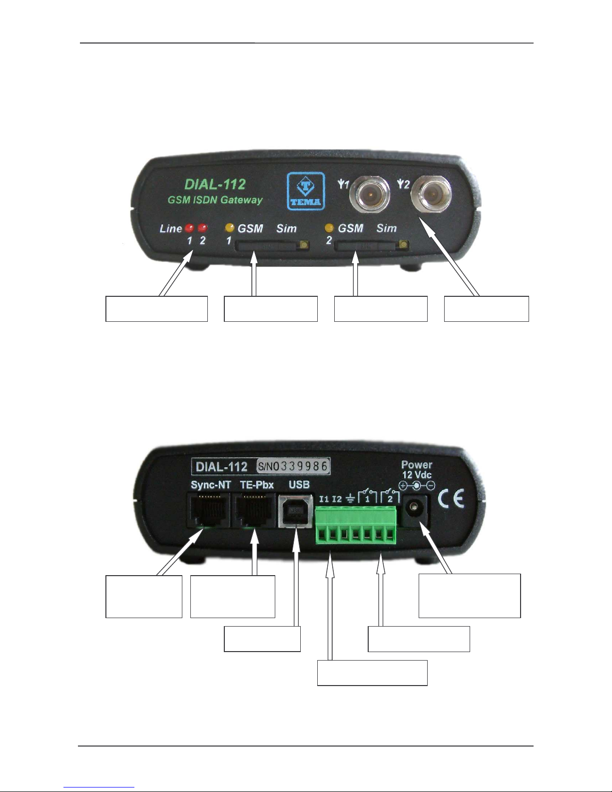
5. DESCRIPTION OF THE DEVICE
5.1. Front view
ISDN LINES 1-2
STATUS
5.2. Rear view
TE PORT TO THE
NT-
FOR
SYNCHRONISM
NT PORT TO THE
SIM CARD SLOT
PBX SIDE
USB SERIAL
CONNECTOR
SIM CARD SLOT
1
1-2 EXTERNAL CONTACTS
2
1-2 RELAYS OUTPUTS
ANTENNA
CONNECTORS
POWER
PLUG
MAS-DIAL112-REV06EN Page 9 of 35

TEMA TELECOMUNICAZIONI SRL
GSM Gateway Interface DIAL-112
6. INSTALLATION AND DIAGNOSTICS
DIAL-112 has two GSM modules that require 2 SIM cards from the telephone operators to work.
The procedure for registering the SIM card on the wireless network when the device is turned on is
automatic and identical to that of a normal GSM telephone.
6.1. Installation of the DIAL-112 unit
In addition to resting on table, a desktop or shelf, the DIAL-112 unit can be wall-mounted, using the
appropriate slots located on its rear panel.
To do that proceed as follows:
• Attach the DIAL-112 to the wall, with the antennas connectors facing upwards.
• Manually screw the antennas connectors (do not use a wrench).
• Connect the ISDN cable from the “TE-Pbx” port to the ISDN port of your PBX (or to a self-
powered ISDN phone).
• For each GSM module, insert the SIM card.
To insert the SIM card into DIAL-112, use a small screwdriver or pen point to press the
centre of the yellow button on the front slot with the SIM holder. Remove the holder and
insert the SIM with the gold contacts facing upwards. Note that there is only one correct
way to place the SIM in the holder. Now, carefully align the holder in the slot and insert it
until it stops in its operating position.
Note
To avoid damaging DIAL-112 or the SIM card, make sure the unit is disconnected from its
power supply before inserting or removing the SIM card.
Important tips for proper operation
We recommend disabling the PIN code request, voice mail, all call diversions (such as
when busy, absent or not available) and call notifications on the SIM card before inserting
the SIM in the DIAL-112, using a normal GSM device with keypad.
• Connect the power supply cord.
6.2. Connection modes
ISDN is a digital system in which communications between various devices must be synchronized
with a common clock. Some PBX (including Alcatel, Ericsson, Philips, Selta, Siemens) can not
tolerate a lack of synchronization between different TE ports.
If you use a PBX with these characteristics is necessary to connect an output of NT at "Sync-NT"
input of DIAL-112 in order to keep the DIAL-112 clock synchronized with other present devices on
NT ports. To connect, use a cable with only 2 connection wires inside (only the RX to the device).
In the diagrams on the following pages are presented several solutions for connecting where are
highlighted the connections and the possible source of signal synchronization.
For the sole purpose of synchronization, DIAL-112 must be connected to a normal NT port, in
order to receive the same clock that the NT port sends to the PBX and on which the PBX
synchronizes (showed in the images with a dotted line).
MAS-DIAL112-REV06EN Page 10 of 35
TEMA TELECOMUNICAZIONI SRL
DIAL
-
112
TE
TE
Extensions
Network
GSM Gateway Interface DIAL-112
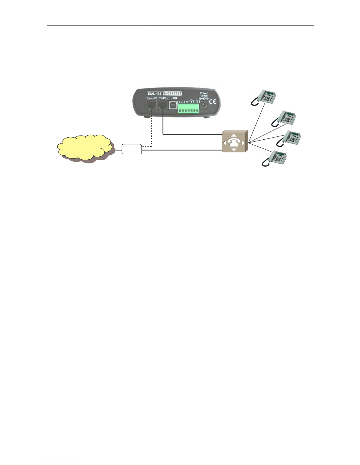
Connecting device as NT (ending) and synchronization from NT port
This method of connection requires that DIAL-112 is related to an external ISDN line (ISDN port
TE) of the PBX: in other words, DIAL-112 has the same role of a new NT port. From the
perspective of the PBX, there is no difference between the external lines available, and between
one or more BRI lines existing and the new BRI attack system offered by the DIAL-112 that goes to
be installed.
PO
ISDN
(BUS T0)
NT
1 BRI ISDN
BUS T0
BUS T0
Internal
PBX
From the "Sync-NT" connector, DIAL-112 is limited to receive the clock synchronism therefore
does not affect in any way traffic between the NT and the PBX. Please note that the ISDN system
provides the Point-Point and Point-Multipoint variants. To function properly, DIAL-112 must be
configured in the same way as the TE port of the PBX connected to it, and set appropriate fields on
the form PTMP PTP in the “General Parameters” mask of the configuration of the device.
Nota 1 If there are multiple ports in the installation, use the sync one of the existing ones that is
configured as Point-to-point, in order of priority from the following:
1. derive synchronization from a port with Point-to-point setup, on which the disabling of level 1 of
the Protocol ISDN does not happen;
2. derive synchronization from a port with Point-to-point setup, configuring the PBX maintaining
always-on the level 1 on this line;
3. If no described above link type is available, obtain the synchronization from the port that made
the most traffic. This will reduce the chance that the port turns off wasting synchronization while
other lines (and their ports) are active.
Nota 2 If more DIAL-112 are connected to the PBX, make sure that all are synchronized to the
same NT port or S0 bus of the plant. If the customer has NT port (for example, has a PRI) and no
S0 free output to use any of DIAL-112 to synchronize the others (take in parallel the central wires
of the TE-PBX port of the first device and connect them to the Sync NT port of the others).
MAS-DIAL112-REV06EN Page 11 of 35
 Loading...