

Tema Telecomunicazioni AA-500-IP, AA-540C, AA-542, AA-542C, AA-545 Technical And Installation Manual
...
Revision
Date Revision reason
Prepared
Checked/Approved
9 13/10/2016 Update MM, DP DP
MAS-AA540-REV09 Page 1 of 60
AA-
500
-IP
Intercom-Doorphone VoIP SIP / PoE
Smart Surface Series
AA-540 4 buttons unit
AA-506K additional keyboard module
AA-506P additional 8 buttons module
AA-506R additional index module
AA-542 2 buttons unit
AA-545 4 buttons and keyboard
AA-546 4 buttons and keyboard and RFID
AA-5xxC IP camera Version
TECHNICAL MANUAL – INSTALLATION
PRELIMINARY DOCUMENTATION
HW version 1.0 - SW version 1.08
Recommendations
1. Use only original spare parts and consumables supplied by Tema Telecomunicazioni Srl for this equipment. The company shall not be
held responsible for any damage caused by the use of materials that they have not supplied.
2. The device has been carefully manufactured and tested. In any case, the product is not recommended for use in situations in which
incorrect operating may result in damage to persons and/or property.
3. We recommend that you carefully read all this manual before starting to use the device.
4. Do not expose the device to sunlight and protect it from sources of heat, dust, humidity and chemical agents.
5. This manual is the property of Tema Telecomunicazioni Srl and any duplication and reproduction, even partial, as well as storage on
any type of media is forbidden without written permission from Tema Telecomunicazioni Srl.
TEMA TELECOMUNICAZIONI S.r.l.
Telecommunications - Electronics

TEMA TELECOMUNICAZIONI SRL
Doorphone AA-540
MAS-AA540-REV09 Page 2 of 60
We, TEMA TELECOMUNICAZIONI SRL Via C. Girardengo, 1/4 - 20161 MILANO
declare under our sole responsibility that the product:
product name Cito telefono - IP SIP VoIP PoE - Doorphone
trade name TEMA TELECOMUNICAZIONI Srl
type or model AA-540, AA-540C, AA-542, AA-542C, AA-545, AA-545C, AA-546, AA-546C
and accessories AA-506P, AA-506KA, AA-506KB, AA-506KC, AA-506R
to which this declaration relates is in conformity with the essential requirements and other
relevant requirements of the R&TTE Directive ( 1999/5/EC, 2006/95/EC, 2004/108/EC ).
The product is in conformity with the followings standards and/or other normative documents:
HEALT & SAFETY EN 60950-1:2006
+A11:2009
+A1:2010
+A12:2011
EMC EN 55022:2010
EN 55024:2010
EN 61000-3-2:2006
EN 61000-3-3 :2008
MILANO, 01 October 2015 TEMA TELECOMUNICAZIONI SRL
D. Pontillo
DICHIARAZIONE DI CONFORMITÀ CE
DECLARATION OF CONFORMITY CE
TEMA TELECOMUNICAZIONI SRL
Doorphone AA-540
MAS-AA540-REV09 Page 3 of 60
I. IMPORTANT INFORMATIONS REGARDING THE RECOVERY AND RECYCLING OF THIS
ELECTRONIC DEVICE
The crossed-out wheeled bin symbol below indicates that this electronic equipment is intended to be disposed in a
separate collection and not in an unsorted municipal waste, in order to provide for the treatment of WEEE (Waste
Electrical and Electronic Equipment) using best available recovery and recycling techniques.
Specific treatment for WEEE is indispensable in order to avoid the dispersion of pollutants and other hazardous
substances into the waste stream, while recycling leads to reduction of disposal of waste and the negative impacts
on environment and human health. That is, priority is given to reuse of WEEE in its components, subassemblies
and consumables.
As the final holder, the user has an important role in contributing to reuse, recycling and other forms of recovery of
WEEE and is responsible to return this waste in the collection facilities set up by EC Member Stases and to fulfill
other duties in compliance with Directive 2002/96/EC and local laws.

TEMA TELECOMUNICAZIONI SRL
Doorphone AA-540
MAS-AA540-REV09 Page 4 of 60
1. OVERVIEW .................................................................................................................................................. 6
2. MAIN FEATURES ....................................................................................................................................... 7
3. PARTS COMPRISING THE SYSTEM (PACKING LIST) ........................................................................ 8
3.1. C
ROSS-REFERENCE TABLE OF FEATURES / SERVICES OF THE VARIOUS MODELS
...................................................... 10
4. TECHNICAL SPECIFICATIONS ............................................................................................................. 12
5. OPERATION .............................................................................................................................................. 14
5.1. B
UTTONS AND NUMERIC KEYPAD EXPANSIONS
.................................................................................................... 14
5.2. P
OSSIBILITY OF OPENING ELECTRIC LOCKS BY ENTERING A PASSCODE
................................................................... 15
5.3. D
EVICE DIAGRAM
............................................................................................................................................. 16
6. OPERATING MODES............................................................................................................................... 17
6.1. DAY / NIGHT / INTERVAL
MODES
................................................................................................................... 17
6.2. A
DDITIONAL FEATURES OF THE KEYPAD EXPANSION
............................................................................................. 17
6.3. RELAYS
CONTROL WITH ACCESS CODES
........................................................................................................... 18
6.4. C
ALLS GENERATED FROM
AA-540 ..................................................................................................................... 18
6.5. C
ALLS TO
AA-540 ........................................................................................................................................... 19
6.6. A
CQUISITION OF EXTERNAL CONTACTS FOR SPECIAL APPLICATIONS
....................................................................... 19
6.7. M
ULTICAST STREAMING AUDIO
.......................................................................................................................... 20
6.8. RFID
READER FOR ACCESS CONTROL
................................................................................................................ 21
7. COMMANDS AND CODES FOR THE INTERNAL OPERATOR......................................................... 22
7.1. S
IGNALING LED AND
AA-540
FRONT PANEL DESCRIPTION
.................................................................................... 23
8. INSTALLATION OF THE DEVICE .......................................................................................................... 24
8.1. W
ALL MOUNTING OF THE SYSTEM
...................................................................................................................... 24
8.2. I
NSERTING OR REPLACING THE NAMES ASSOCIATED WITH THE BUTTONS
................................................................ 25
8.3. CONNECTIONS ............................................................................................................................................ 26
8.3.1. C
ONNECTION OF THE BASE SYSTEM
AA-540 .......................................................................................... 26
8.3.2. C
ONNECTING THE SYSTEM EXPANSION
AA-506P
AND
AA-506K .............................................................. 27
8.3.3. C
ONNECTING THE SYSTEM EXPANSION
AA-506R.................................................................................... 28
8.4. D
ESCRIPTION OF THE TERMINAL BLOCKS OF RELAYS
............................................................................................ 29
8.5. D
ESCRIPTION AND EXAMPLES OF OPERATION MODES WITH THE INTERNAL RELAYS, CONNECTIONS
............................ 30
8.5.1. CASE 1 –
DRIVE OF TWO ELECTRIC LOCKS WITH SYSTEM POWERED
......................................................... 30
8.5.2. CASE 2 –
DRIVE OF TWO ELECTRIC LOCKS, SYSTEM POE POWERED, ONE POWER SUPPLY
.......................... 31
8.5.3. CASE 3 –
DRIVE OF TWO ELECTRIC LOCKS WITH SYSTEM POWERED WITH 3 DIFFERENT POWER SUPPLIES
..... 32
8.5.4. CASE 4 –
DRIVE OF TWO ELECTRIC LOCKS, SYSTEM POE POWERED, TWO SEPARATE POWER SUPPLIES
....... 33
8.5.5. CASE 5 –
DRIVE OF AN ELECTRIC LOCK AND AN OPENING BUZZER
............................................................ 34
8.5.6. I
NPUT CONNECTION FOR ACQUISITION OF EXTERNAL CONTACTS
................................................................ 35
8.5.7. C
ONNECTION BETWEEN BASE UNIT AND EXPANSIONS
.............................................................................. 36
9. PROGRAMMING ...................................................................................................................................... 38
9.1. P
REPARING FOR PROGRAMMING SYSTEM PARAMETERS
....................................................................................... 38
9.2. A
CCESS TO PROGRAMMING AND RESET ADDRESS AND PASSWORD
........................................................................ 40
9.3. N
ETWORK PARAMETERS
................................................................................................................................... 41
9.4. SIP
PARAMETERS
............................................................................................................................................ 42
9.5. G
ENERAL PARAMETERS
.................................................................................................................................... 43
9.6. S
ET OF THE OPERATING MODE
.......................................................................................................................... 45
9.7. R
ELAY AND INPUT SETTINGS
............................................................................................................................. 46
9.8. C
AMERA
......................................................................................................................................................... 48
9.9. C
ALL BUTTONS
................................................................................................................................................ 49
9.10. M
ESSAGES MANAGEMENT
........................................................................................................................... 51
9.11. RFID
MANAGEMENT
................................................................................................................................... 53
9.12. C
ALLS REPORT
........................................................................................................................................... 54
10. MAINTENANCE ........................................................................................................................................ 55
10.1. S
YSTEM
.................................................................................................................................................... 55
10.2. L
OGIN CREDENTIALS
................................................................................................................................... 56
10.3. D
IAGNOSTIC LOG
........................................................................................................................................ 56
11. PRESENTATION AND USE OF THE PROGRAM "AA Video Console" .......................................... 57
11.1. P
RESENTATION
.......................................................................................................................................... 57
11.2. S
OFTWARE CONFIGURATION FOR
SIP S
ERVER MODE
..................................................................................... 58

TEMA TELECOMUNICAZIONI SRL
Doorphone AA-540
MAS-AA540-REV09 Page 5 of 60
11.3. S
OFTWARE CONFIGURATION FOR PEER-TO-PEER MODE
................................................................................. 59
TEMA TELECOMUNICAZIONI SRL
Doorphone AA-540
MAS-AA540-REV09 Page 6 of 60
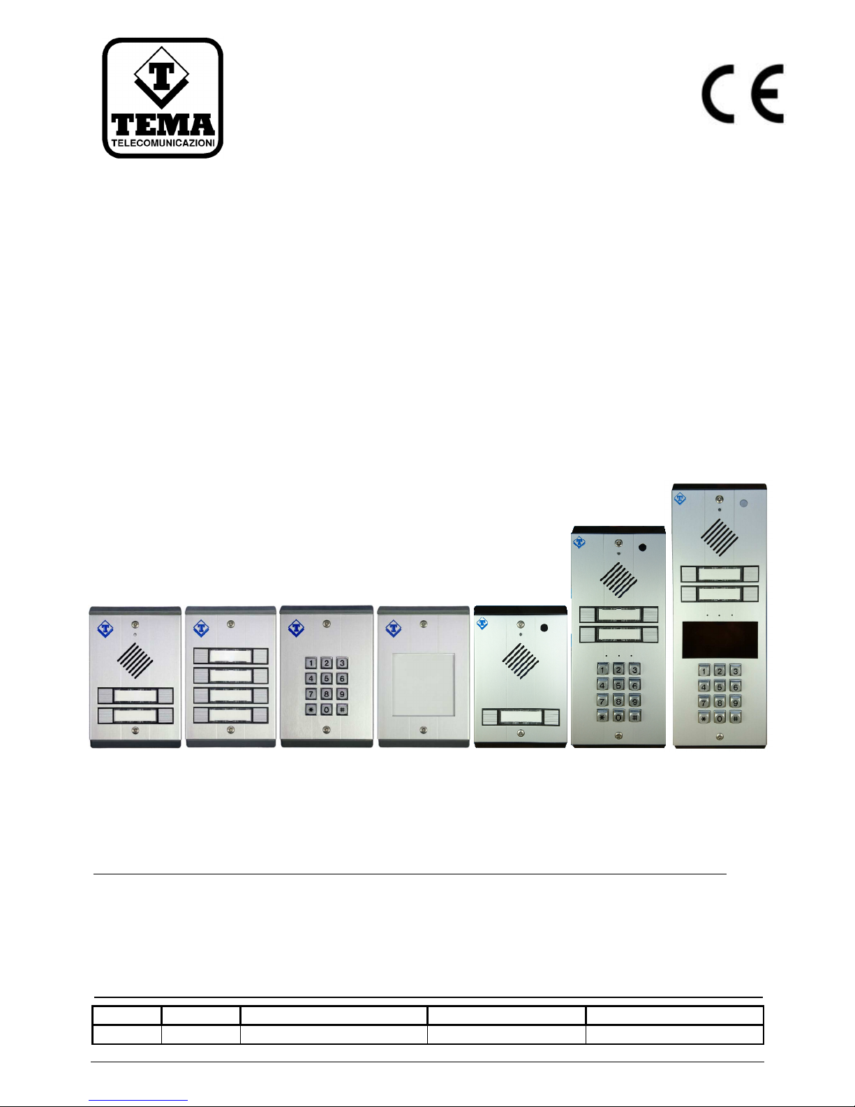
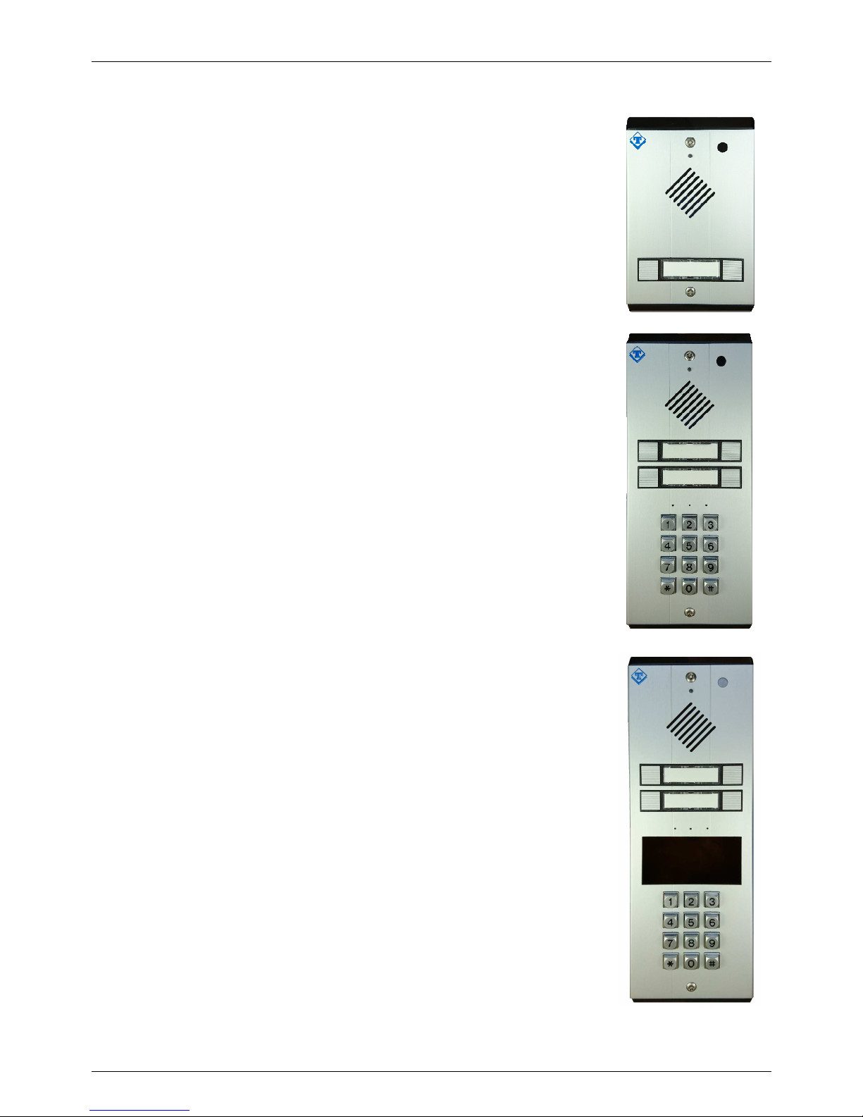
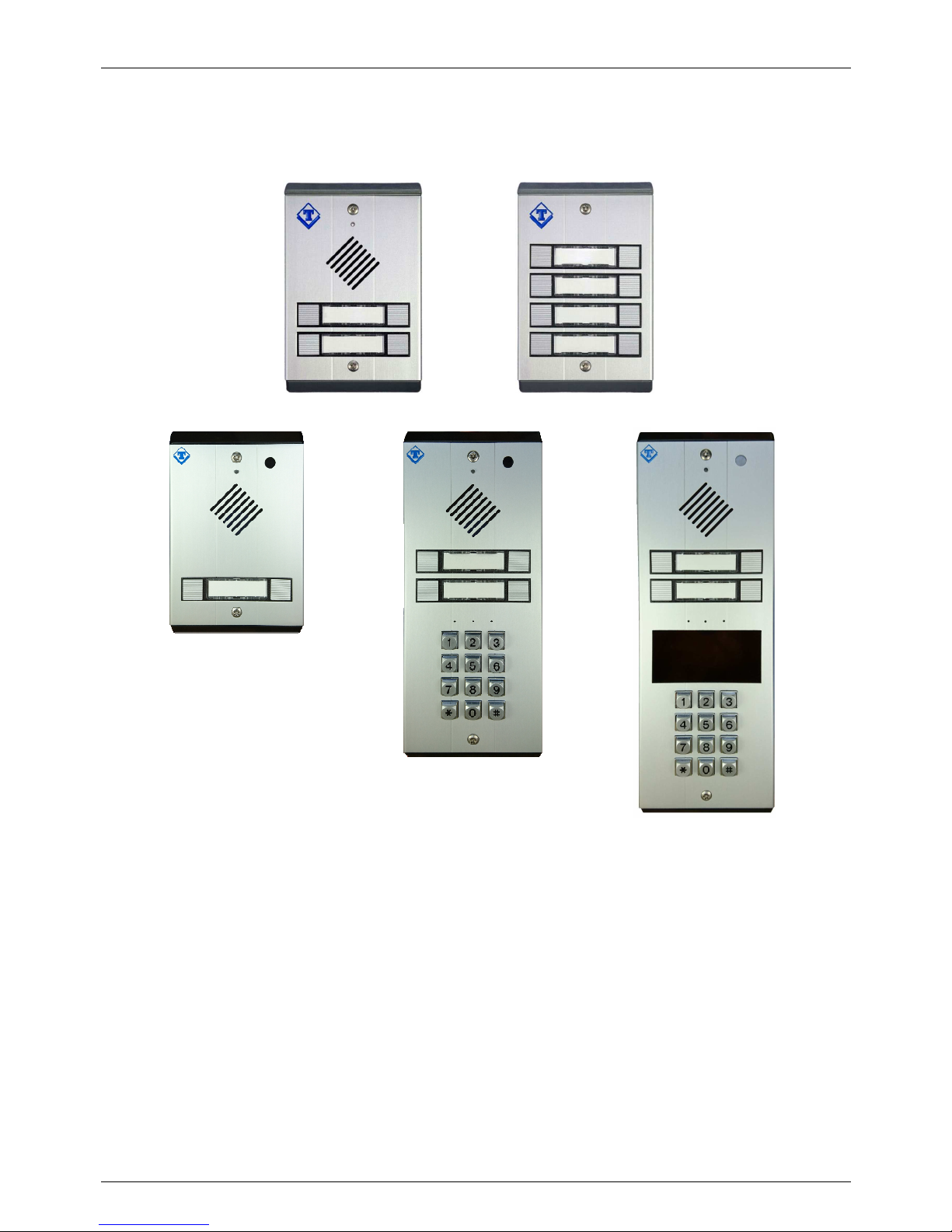
1. OVERVIEW
The AA-540 is a Doorphone that can be connected to any VoIP SIP PBX, as a SIP extension, with the possibility of
power either through dedicated external power adapter, or through PoE on the LAN. Alternatively it is possible to
be used in a Peer-to-Peer connection and allows the opening of one or two electric locks (two integrated relays).
AA-540 AA-506P AA-506K AA-506R AA-542 AA-545 AA-546
AA-540 is installed for example on a gate for external control and when a visitor presses one of the buttons to show
up, make a VoIP phone call to the number of the operator, allowing audio communication. Once it is established
that the visitor must enter into the company, the operator may open directly from his phone, with a DTMF tones
code, the electric gate or pedestrian gate.
AA-540 can be programmed with a web interface reachable from any PC connected to the corporate LAN, using a
common web browser by typing the IP address of the device.
In addition, thanks to the integrated color camera (version AA-540C), it is possible to see the visitor directly to the
operator's internal IP video phone or on the screen of his PC with a standard internet browser, ensuring the
maximum security of the framed area.
AA-542 is a non expandable reduced button unit version
AA-545 is a non expandable unit version with embedded keyboard
AA-546 is a non expandable unit version with embedded keyboard and RFID mudule
Parts of the AA-500-IP serie; AA-38 transparent rain shield, AA-519-T1, AA-519-T5, AA-519-T6 aluminium rain
shields and AA-39AL power adapter. Each rain shield module is intended to protect a single module and to be used
joined side by side to protect base unit plus expansions modules.
AA-38 AA-39 AA-519-T1 AA-519-T5 AA-519-T6 AA-39AL

TEMA TELECOMUNICAZIONI SRL
Doorphone AA-540
MAS-AA540-REV09 Page 7 of 60
2. MAIN FEATURES
Generals
•
Make a phone call after the press of a button on the device
•
Programming via Web interface with password protection
•
Operation modes Day / Night / Interval (with manual or automatic mode) for different numbers of call
destination
•
Two door opener relays for possibility of activation of a second electric lock, for example to make the
distinction between pedestrian gate and driveway gate
•
Up to 6 programmable codes (3 for each relay associated with electric lock) to drive the relay directly from
the door without the intervention of the operator
•
Setting the operation mode Day / Night / Interval via telephone or in automatic (time slots), retention of the
settings also after a power failure
•
Backlight of the key label holder and integrated internal anti-humidity heating system
•
Great versatility and ease of use and programming
•
Hands-free talking with high audio quality
•
Possibility to upgrade the software / firmware via LAN
•
Possibility to acquire up to 3 external contacts to the system and warning service with dedicated messages
•
Possibility to receive and send RTP MULTICAST audio streaming, for paging announce, up to 5 receive
priority leves
•
Possibility to activate a second SIP account, used for “Night ringer” group
•
Possibility to protect the audio connection for incoming calls with a code (monitor)
•
“Push-to-talk” function, using any input
•
“Opendoor” function, using any input
•
Possibility to play a prerecorded announcement message, with a telephone code or using any input
•
Models with optional RFID wireless cards and TAG reader for access control, actibity log
•
RFID control table also usable for access control via keyboard
VoIP IP LAN section
•
Integration with the local LAN, 100 BaseT Ethernet port with RJ45 connector
•
SIP-based VoIP connection in either SIP Proxy Server or Peer-to-Peer mode, PoE (Power over Ethernet)
possibility
•
Up to 2 programmable numbers are available by each button, with possibility of supervisor and call cycles;
ability to associate a SIP extension number or an IP address, according to the connection mode SIP Proxy
Server or Peer-to-Peer
Integrated color camera (version AA-5xxC only)
•
Integrated color camera
•
Video Streaming over IP phone with video support, or on a PC using a web browser, or using the supplied
software "AA Video Console”
•
Image storing: snap photos when the call button is pressed by the visitor, with the possibility of sending the
same email in real time
TEMA TELECOMUNICAZIONI SRL
Doorphone AA-540
MAS-AA540-REV09 Page 8 of 60
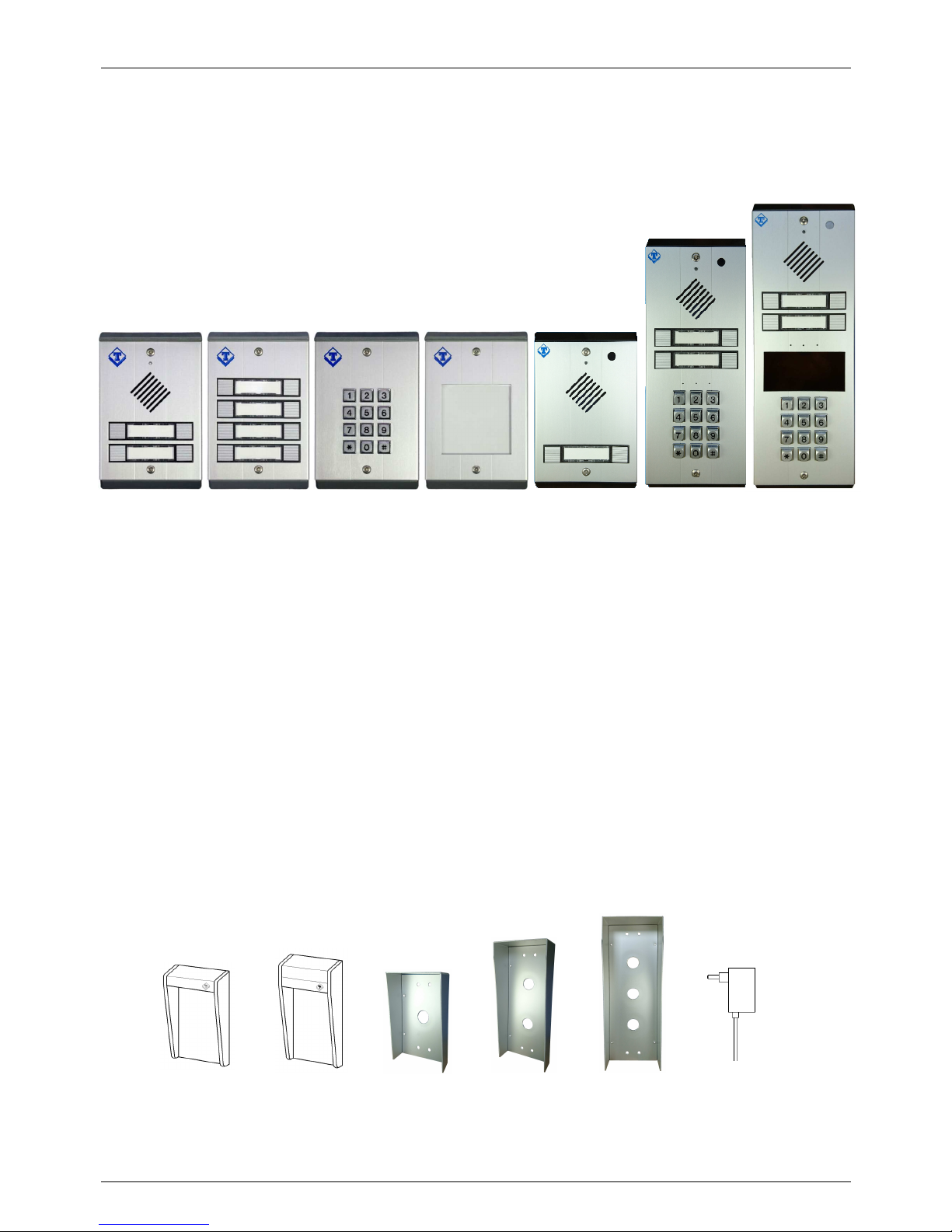
3. PARTS COMPRISING THE SYSTEM (PACKING LIST)
The AA-540 system consists of the parts included in the following list:
• An AA-540 device (external unit with 4 buttons)
• Four anchors and four screws for wall mounting
• A special key for the front panel screws
• A foam seal to be interposed between the back of the system and the wall
• A set of die cut labels with extractor for label holders
• A CD-ROM with documentation and technical manual
• A drilling sheet
The AA-506P expansion consists of the parts included in the following list:
• An AA-506P module (8 push buttons)
• Cable for connection to the base unit AA-540
• Four anchors and four screws for wall mounting
• A special key for the front panel screws
• A foam seal to be interposed between the back of the system and the wall
• A set of die cut labels with extractor for label holders
• A drilling sheet
The AA-506K expansion consists of the parts included in the following list:
• An AA-506K module (full numeric keypad)
• Cable for connection to the base unit AA-540
• Four anchors and four screws for wall mounting
• A special key for the front panel screws
• A foam seal to be interposed between the back of the system and the wall
• A drilling sheet
The AA-506R expansion consists of the parts included in the following list:
• An AA-506R module (Legend)
• Four anchors and four screws for wall mounting
• A special key for the front panel screws
• A foam seal to be interposed between the back of the system and the wall
• One die cut label for the index legend (already inserted in the system)
• A drilling sheet
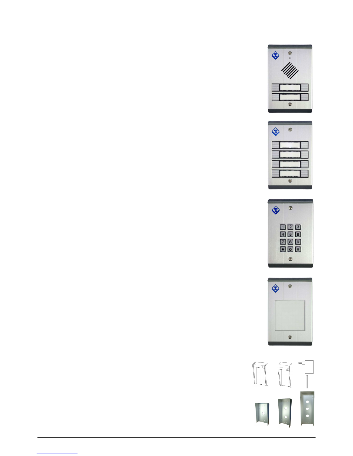
It is possible to add also the following accessories:
• AA-38 Transparent rain shield (AA-39 only on request)
• AA-519-T1 Short size aluminium rain shield
• AA-519-T5 Mid size aluminium rain shield
• AA-519-T6 Long size aluminium rain shield
• AA-39AL Power supply adapter
• Plastic enclosure Kit colors (AA-509BK Black, AA-509YE Yellow,
AA-509GR Grey, AA-509RD Red)
TEMA TELECOMUNICAZIONI SRL
Doorphone AA-540
MAS-AA540-REV09 Page 9 of 60
The AA-542 system consists of the parts included in the following list:
• An AA-542 device (external unit, 2 buttons)
• Four anchors and four screws for wall mounting
• A special key for the front panel screws
• A foam seal to be interposed between the back of the system and the wall
• A set of die cut labels with extractor for label holders
• A CD-ROM with documentation and technical manual
• A drilling sheet
The AA-545 system consists of the parts included in the following list:
• An AA-545 device (external unit, 4 buttons, keyboard)
• Four anchors and four screws for wall mounting
• A special key for the front panel screws
• A foam seal to be interposed between the back of the system and the wall
• A set of die cut labels with extractor for label holders
• A CD-ROM with documentation and technical manual
• A drilling sheet
The AA-546 system consists of the parts included in the following list:
• An AA-546 device (external unit, 4 buttons, keyboard, RFID)
• Four anchors and four screws for wall mounting
• A special key for the front panel screws
• A foam seal to be interposed between the back of the system and the wall
• A set of die cut labels with extractor for label holders
• A CD-ROM with documentation and technical manual
• A drilling sheet
TEMA TELECOMUNICAZIONI SRL
Doorphone AA-540
MAS-AA540-REV09 Page 10 of 60
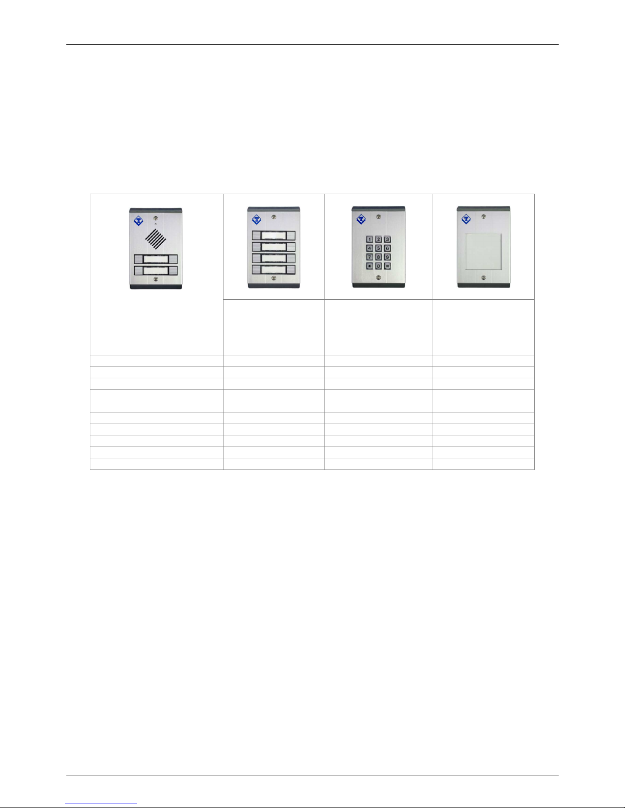
3.1. Cross-reference table of features / services of the various models
At the base model AA-540 only, it is possible to add one expansion module chosen between AA-506P and AA506K while it is possible to add one or more AA-506R modules.
The keyboard module is available in three versions, AA-506KA with plastic keyboard, AA-506KB with metal
keyboard and AA-506KC with metal backlighted keyboard.
The expansions AA-506P or AA-506K are connected and powered directly from the base unit via a supplied cable,
expanding the functions of the base system:
Expansion AA-506P
Expansion AA-506KA
Expansion AA-506KB
Expansion AA-506KC
Expansion AA-506R
Numbers of buttons
8 -- --
Telephone Keypad
-- Yes --
Door openi
ng codes
Yes Yes --
Button matching to the
phone number
Yes Yes (keys from 1 to 9) --
Direct number dialing
-- Yes --
Speed dial
-- Yes --
Possibility of filter/prefixdigits
-- Yes --
Backlighting
Yes Only AA-506KC keys Yes
Label holder
Yes, buttons -- Yes, front area
+
AA-540
TEMA TELECOMUNICAZIONI SRL
Doorphone AA-540
MAS-AA540-REV09 Page 11 of 60
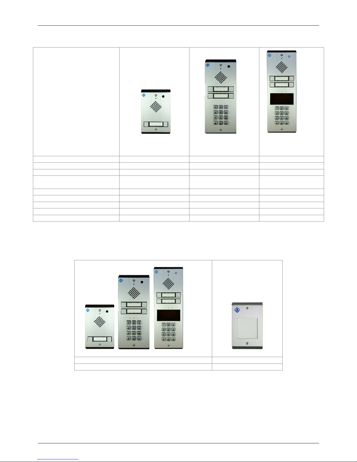
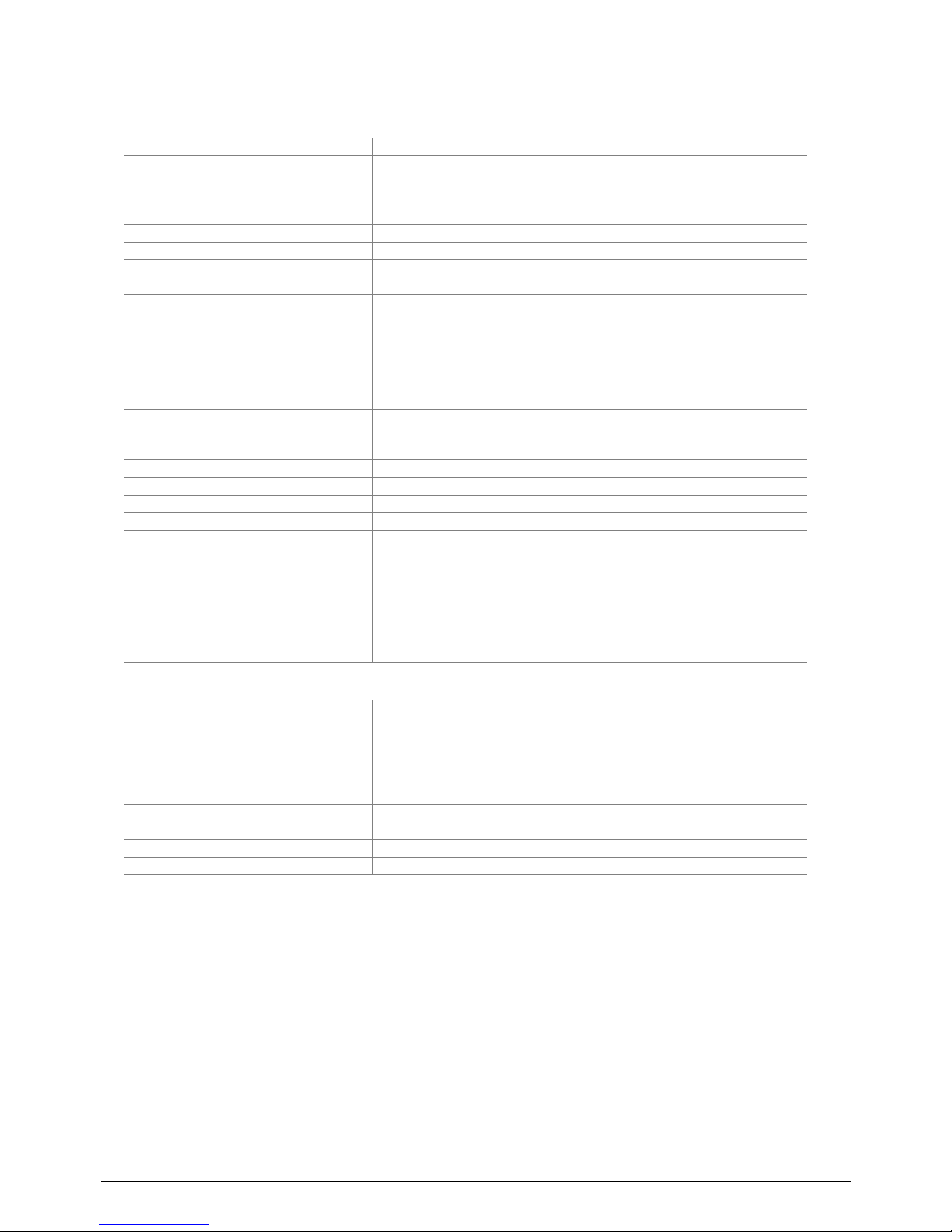
AA-542
AA-545
AA-546
Numbers of buttons
2 4 4
Telephone Keypad
-- Yes Yes
Door opening codes
Yes Yes Yes
Button matching to the
phone number
Yes Yes (keys from 1 to 9) Yes (keys from 1 to 9)
Direct number dialing
--
Yes Yes
Speed dial
--
Yes Yes
Possibility of filter/prefixdigits
--
Yes Yes
Backlighting
Yes Yes + keyboard Yes + keyboard
Label holder
Yes Yes Yes
AA-542, AA-545 e AA-546 models can connect only to one o r more AA-506R expansion module.
There is no way to connect them to expansion keyboard or button modules.
Espansioni AA-506R
Backlighting
Yes
Label holder
Yes
+
+
TEMA TELECOMUNICAZIONI SRL
Doorphone AA-540
MAS-AA540-REV09 Page 12 of 60
4. TECHNICAL SPECIFICATIONS
Generals
Buttons
Buttons with backlighted label holder
Internal heating
Anti-humiditiy internal heating circuit
Audio section
Internal speaker with RMS power 1.3W
Possibility of adding an external speaker, RMS power of 1.3W
and minimum impedance 8Ω.
Insertion type terminals for
cables
Possibility to use cables up to 1.5mm
2
or AWG16
Number of built
-
in relays
2
Max relay contacts load
30V – 2A
Power Supply
12VDC
/ VAC, 9
00mA max
Power Supply expansion mod
ules
They are connected by cable to the
base unit
AA-506P
backlight circuit
max. 140 mA
AC
AA-506P heating circuit max. 310 mAAC
AA-506K backlight circuit max. 020 mAAC
AA-506K heating circuit max. 310 mAAC
AA-506R backlight circuit max. 140 mAAC
AA-506R heating circuit max. 310 mAAC
Material of the container
Corrosion
-
resistant aluminium 9006/1
-
T6 (6060
-
T6)
Buttons body in Mackrolon® Polycarbonate (UL94-V2)
ABS Novodur® heads
Mounting type
Wall mounting
IP grade of protection
IP54
Operating Tempe
rature
From
-20˚C to +50˚C
Relative humidity
95% not
-
condensing
Dimensions and weight
AA-
540
L 101 x H 156 x D
45 mm
- 410g
AA-542 L 101 x H 156 x D 45 mm - 400g
AA-545 L 101 x H 247 x D 45 mm - 650g
AA-546 L 101 x H 293 x D 45 mm - 750g
AA-506P L 101 x H 156 x D 45 mm - 320g
AA-506K L 101 x H 156 x D 45 mm - 390g
AA-506R L 101 x H 156 x D 45 mm - 280g
VoIP
PoE power supply
According to IEEE 802.3af
(only for system powering, not for opening electric lock)
LAN Ethernet LAN 100 BaseT
port
Supported VoIP Protocols
SIP v2
Supported connecting modes
SIP Server or Peer
-to-
Peer
Protocols
IP, TCP, UDP, http, TELNET, SIP, RTP
Bandwidth
300 –
3400 Hz
Audio codec
G711µ, G711a
, G722
Echo soppressor
Yes
MULTICAST
RTP
s
treaming audio
Yes

TEMA TELECOMUNICAZIONI SRL
Doorphone AA-540
MAS-AA540-REV09 Page 13 of 60
Inputs contacts
Insertion type terminals for input
Possibility of use of cables up to 1.5 mm
2
or AWG16
Number of inputs
3 distinct with common
terminal
connector
Type of drive
For each input, acquisition of a voltage
-
free contact for
connection between the individual input and the common point of
the dedicated connector (TB5 pin 3,4,5,6)
Time for change state detection
Closing or opening of the stable external contact for at least 100
milliseconds, any less time trigger will be ignored
Voltage
for
detection state contacts
12VDC max, the system has its
internal
voltage
reference
to
detect contact closure
Current
for
detection state contacts
Max 10 mA, with the closed contact to the common point
Note:
it is not possible to
apply any voltage at the
terminal points dedicated to the acquisition of the inputs
state
(TB5 pin 3,4,5,6), because it will damage the system
Note: the individual inputs (including the common point) are not galvanically isolated from each other
Integrated Camera (only AA-5xxC versions)
Type
Color camera
Video resolution
640 x 480
352 x 288
320 x 240
176 x 144
View angle
70°
Video output
IP Video streaming, H.263, H.263+
, H264

TEMA TELECOMUNICAZIONI SRL
Doorphone AA-540
MAS-AA540-REV09 Page 14 of 60
5. OPERATION
The working unit behaviour in that guide is mainly referred to the AA-540 unit. The same applies to all others
models with the exception of services directly dependent from hardware specific equipements (i.e. camera module,
button numbers or expansion, keyboard, RFID and so on).
When the call button in idle mode is pressed, AA-540 automatically generates a telephone call through the VoIP
PBX. The visitor begins to listen to the speaker of AA-540 the outcome of his request for access, or listen to the
ringing tone and the subsequent reply by the operator that was called.
Optionally, before forwarding the call, it is possible to set a message playing (matched to each key and each
mode), such as "The company is closed, wait for the reply from the operator...".
The operator who asnwers to the visitor can immediately decide to activate the electric lock directly typing the
correct sequence of programmed DTMF digits codes (opening the door), and hang up when finished. When the
user hangs up, AA-540 will return to the idle state recognizing the closing and will be ready for a new access
request.
It is also possible for the operator or other extensions to call the phone number where AA-540 is connected to
reach the Doorphone, to speak with people close to the entrance and to activate the electric lock without waiting for
a visitor call. It is also possible to protect this feature with a connection/listening code.
It is possible to adjust the audio level of AA-540 in order to better adapt to the acoustic characteristics of the area
where it is installed.
With the AA-540C version, which has an integrated color camera, it is possible to see the framed area. The video
of the camera is carried on an IP Stream directly on the corporate LAN using the same LAN cable for connecting
AA-540C. It is possible to see the framed area on an IP phone with video capability or directly to a PC via a
standard browser.
5.1. Buttons and numeric keypad expansions
Adding the AA-506P expansion, it is possible to have 8 extra buttons, to get up to 12 call buttons in total. Adding
instead the AA-506K expansion it is possible to have the telephone keypad that allows some additional services.
There is for example the possibility for the visitor to directly call a phone number, or to call the numbers
(appropriately pre-programmed in the parameters) of the Speed Dial operating mode.
See for example the case of a possible visitor who goes to the entrance of a building site and among the dozens of
companies on the job site must conctat one in particular: just provide a legend in the proximity of the device that
has the instructions and the various numbers to call to get in touch with the person of each company.
The same operation mode may be applicable in public facilities, large buildings and other environments. The calls
(if allowed by the appropriate class of service of the extension number assigned to AA-540 on the PBX) can also be
made to mobile phones or trunks and not only just to the extensions of PBX to which it is connected.
It is also possible to dial only the final part of the number using the operation mode with a root number. In this case
the system prepends to the dialed number on the keypad a pre-programmed prefix. For example, if the root number
is "3" and the user types on the keyboard "14", the system will associate the prefix and dial the number "314". This
service is also found useful to mask the true extension number of the person to contact.
In addition, this field or service may be used to avoid to make calls directly from the system, when equipped with a
AA-516K keypad, engaging the external lines of the connected PBX. In fact, if a visitor will try to make dial
02123456, the system will call 302-123456 preventing the external call.
TEMA TELECOMUNICAZIONI SRL
Doorphone AA-540
MAS-AA540-REV09 Page 15 of 60
The direct dialing mode is NOT an alternative to the speed dialing mode and can both work.
Below is shown the position of the buttons with their logic mapping on systems.
5.2. Possibility of opening electric locks by entering a passcode
It is also possible to allow the access to some employees making them aware of a code (this feature can be
enabled or disabled) so that they can have access without the operator intervention, simply by typing the code in
the right sequence on the keys of the Doorphone.
For example set the code "221441", who knows it will have to press the buttons in the right sequence
2+2+1+4+4+1 of the Doorphone buttons for the opening of the electric lock. This particular feature can be useful in
case of installation of Doorphone, for example, in a doctor's office, a hallway or in all those cases where the public
(not authorized) must call the operator while internal employees can instead have access by using this kind of
authorization. AA-542 can only dispose of buttons 3 and 4 combination codes.
Please note that if the system features the expansion keyboard, the access code must be entered by preceding the
star digit (*). The star digit must be dialed to tell the system that is entered an access code rather than dialing a
number.
It is possible to define codes that only work in Day mode or other only for Night or Interval mode.
AA-540 AA-506P
3
1 2
4
5
7
6
9
8
10
11 12
AA-
545
1
1
2 2
3 3 4 4
AA-
546
3
4
AA-
542
TEMA TELECOMUNICAZIONI SRL
Doorphone AA-540
MAS-AA540-REV09 Page 16 of 60
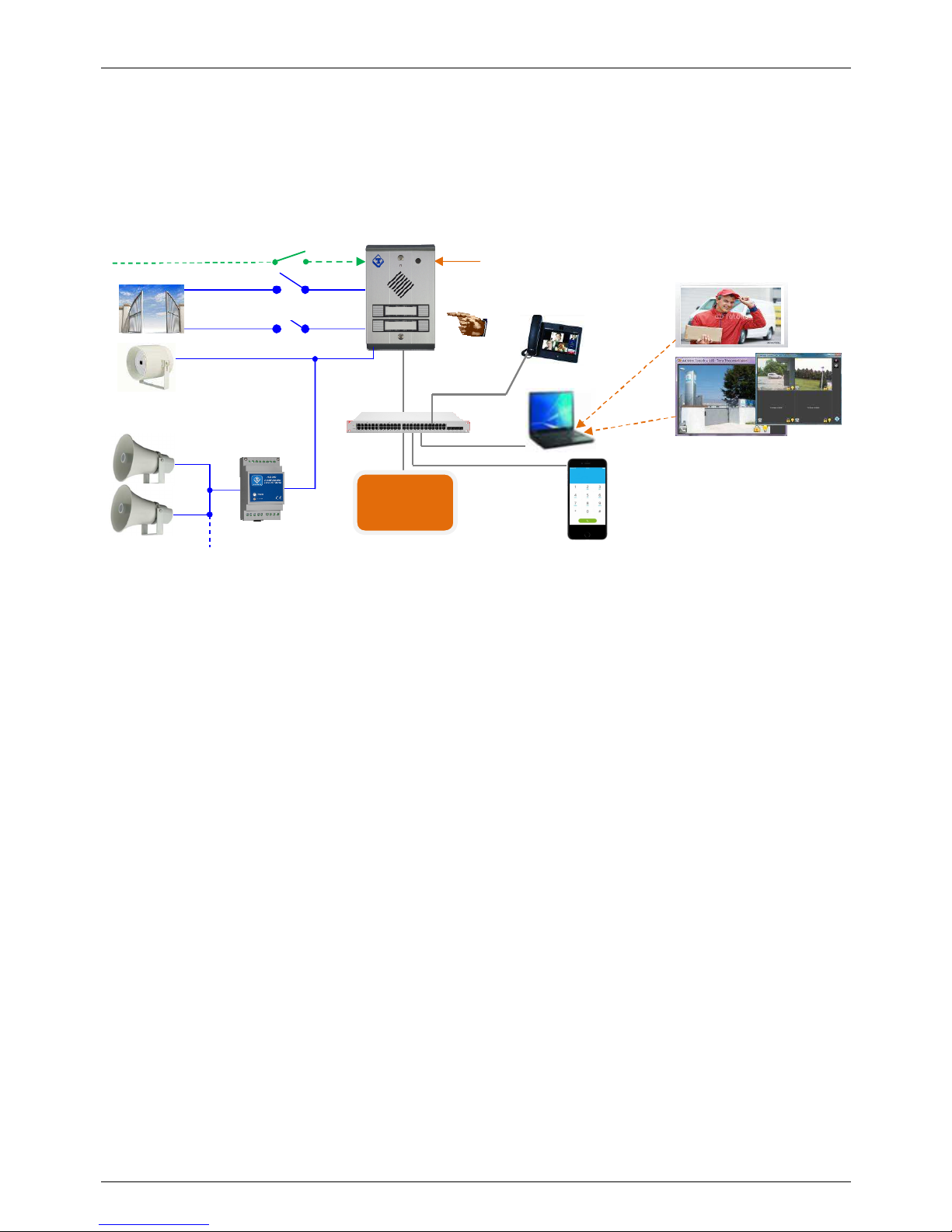
5.3. Device diagram
The AA-540 Doorphone is connected to the PBX via the LAN RJ-45 port. The contacts of relays will be used to
drive an electric door opener and/or a light at the entrance, a gate for pedestrian and/or the driveway gate.
The figure below shows an example of Doorphone connection:
Description of the new features made available by installing AA-540 in the company:
•
The visitor that press one of the Doorphone buttons will be put in contact with the operator who may decide
to open the electric lock from his telephone and give way to access the company. In the same way he may
decide to open the driveway gate to give access to a vehicle.
•
The operator who has been able to monitor the video in the area, can directly operate the two possible
access gates, without waiting for the visitor to press the buttons on the Doorphone.
•
During the Night mode, when the operator is no longer present in the company, the call generated by the
Doorphone can be forwarded to a telephone number of a guardian that could open the gates and let the
visitor to access by acting the relays even remotely (eg. being reached with a call to his mobile phone).
•
The two integrated relays could be used, in another case, one for the gate and the second to activate a
lighting system of the entrance area, to be activated only when there is a transit of persons or vehicles.
Tipical application
User PC
LAN Switch PoE
2 integrated relays
Color IP camera (only AA
-
540C model)
IP videophone
Audio and Video with a
standard “Softphone”
IP PBX
APP for
SmartPhone,
Audio, Video
and remote
commands
Audio
and Video
with TEMA
software
“Videoconsole” for Windows PC,
up to 16 AA-540C access stations
Direct exit for external
speaker 8 Ohm-3W
Exit for
30W
amplifier
(Tema AD301) and
Up to 3 external inputs
Visitor

TEMA TELECOMUNICAZIONI SRL
Doorphone AA-540
MAS-AA540-REV09 Page 17 of 60
6. OPERATING MODES
The system has the label holders combined with the buttons. When a visitor presses one of the buttons, the system
make a call on a PBX extension associated with the pressed button.
The numbers that are called may differ depending on the operating mode in which the system is programmed, Day
- Night mode / Interval mode, (see par. 9.6).
If the system AA-540 is equipped with the 8 buttons expansion the operation described below for the 4 buttons on
the base system remains valid and is extended to additional buttons.
In the case of keyboard expansion, are valid the same informations as stated for the buttons on the base system
while the keyboard allows to dial the desired number, or to handle additional functions described later.
If is used the keyboard in Speed Dial mode, described below, the descriptions of the operating modes listed below
are valid only for the numbers associated with the Speed Dial service.
6.1. DAY / NIGHT / INTERVAL modes
In each of the three possible operating modes, the system makes a call to a number after pressing a button (or call
to two numbers if also the second number is programmed) for a configurable number of times. It is also possible to
specify an additional final number, called the "supervisor", to contact at the end of the previous programmed
attempts. The call is considered successful when the operator answers.
The visitor hears the signalings of the current call preceded by a greeting voice message, when enabled.
If the visitor presses a button again while the call is in progress, the system stops the call and returns to standby.
For the systems with the keyboard expansion you must press the star key (*) to stop the call.
The system can be manually placed in a Day, Night or Interval (the operator will send a special command to the
system), or it can automatically switch to each mode according to a time schedule.
The active mode is stored also when the system is powered off and then reactivated when it will be powered on.
6.2. Additional features of the keypad expansion
If the expansion module AA-506K is installed, the visitor can make a call simply by dialing the desired number if
known by him or presented into an index table placed near the Doorphone (eg the AA-506R expansion), typing it
directly on the keyboard.
The introduced number to dial is considered finished after about two seconds after the last dialed digit by the
visitor. It is possible to speed up the dialing without waiting for the system timeout by pressing the pound key (#) at
the end of the number, in which case the call is made immediately.
The visitor, realizing that has made mistakes in typing can be immediately cancel the entered digits by pressing the
star key (*), the same key has the function to break down if the call is already in progress.
In addition to direct dialing mode, the keypad allows for Speed Dial function, in which it is possible to associate a
number to call to each digit of the keyboard (10 phone numbers associated with the digits from 0 to 9, see par. 9.9),
with the possibility to differentiate between Day, Night and Interval.
According to the system mode, the visitor can then contact one of the 30 numbers entered. The Speed Dial mode
is NOT exclusive but coexist with the possibility of direct dialing with the only exception that it is not possible to
directly dial single digit numbers. Having to select the visitor directly to a single-digit numbers it is not possible to
use the Speed Dial service.
The Speed Dial feature (single digit of the keyboard) behaves as pressing a button on the base system and it is
also adjusted according to the parameter 118 about the operation in Day/Night mode, Day/Night with repeating
calls, or Group mode. In practice, for the user, the keyboard also adds 10 more call buttons.
By directly dialing the number to call on the keyboard, may be possible for the visitor to dial a number that you do
not want to be dialed, or at least reached (eg outside the company). To avoid this possibility it is possible to use a
prefix before the number to be dialed. If the numbers of operators are in the numbering plan of the PBX (internal
extensions), it is sufficient to program the parameter with the first digit of the numbering plan and expose the

TEMA TELECOMUNICAZIONI SRL
Doorphone AA-540
MAS-AA540-REV09 Page 18 of 60
legend for visitors with numbers to reach without the first digit. For example, to call the operator at the extension
number 311 it must be programmed the prefix with a value of 3 and indicate to the caller to dial the number 11.
In the case there is the need that the the visitor must dial external numbers, this parameter may be useful if filled
with the value of a code that instructs the PBX to use a specific trunk group for outgoing governed by the desired
class of service, with restrictions on certain numbers for calls when the PBX allows it (long distance calls, foreign
calls, fee-based services, mobile network, etc.).
In other cases, remember to activate some kind of control on the possible numbers that a general visitor can dial to
prevent unauthorized calls.
AA-540 is equipped with a special table of up to 60 characters that allows to create a filter on the selections made
by the user, in order to allow or reject it, even without the control of the PBX. This table and this service are very
useful for systems equipped with the full keyboard expansion module.
6.3. RELAYS control with access codes
The opening function of the door opener connected to the two relays can be made available to a visitor who is
familiar with the various preset access codes.
The code is made up by the alternating pressure of the buttons of the device: for example, the code "121212" on
the system AA-540 correspond to press the first and the second button in sequence three times. It is possible to set
up to three access codes for each relay, one for the Day mode, one for Night mode and one for the Interval mode
(see par. 9.7). Upon the detection of the correctly inserted code, the corresponding relay will be activated for the
time set in the parameter.
The opening codes for the system based on 4 buttons will obviously consist of combinations of single digits from 1
to 4. If the system is equipped with the AA-506P expansion with 8 additional buttons it is actually possible to use all
the digits excepts zero (1-9).
If the system uses the AA-506K expansion, the opening codes must be typed directly on the keyboard preceded by
the star key (*) to distinguish them from a normal telephone call. The visitor will get access without operator
intervention (for example, useful to service personnel or external assistance, which for work reasons comes out
and returns back frequently in the company).
Relays can be also actuated with any of input signals (for example it is possible to connect an internally installed
push button for exit), see in the “Alarms – Inputs setting” programming mask the “Call” field.
6.4. Calls generated from AA-540
These are the calls that the system generates on the line, triggered by the pressure of the button by a visitor by the
previously described ways.
Who answers the call can speak to the caller for a fixed time set in the general parameters (see. par. 9.5). If the
conversation goes on, warning tones will be played in the phone so that the operator can enter the code “#5” to
extend the call duration.
Also during the conversation, the operator can enter a code to open the door (see. par. 9.5). Once the door was
opened, the conversation may be closed or not, according to the programming of the relay. If it is configured so that
the call is not closed, it will remain active until the timeout expires or, if the operator hangs up, the system will return
immediately in standby mode.

TEMA TELECOMUNICAZIONI SRL
Doorphone AA-540
MAS-AA540-REV09 Page 19 of 60
6.5. Calls to AA-540
Call the system AA-540 from the PBX phones is useful to activate the conversation or issue commands for
example when a visitor is detected near the Doorphone, through a video surveillance system of the gate, or if some
vehicle arrived at the entrance driveway or as announcer to serve certain areas of warehouses without using a
more complex system of public address audio diffusion.
Calling the extension number connected to the AA-540 system, it will answer after a preset time. In conversation
the caller has the same commands described above for incoming calls to trigger the door opening and other
controls such as the change of the operating mode, and more.
It is possible to set the reply of the system by pressing a button of the Doorphone. This service, governed by
general parameters (see. par. 9.5), allows to avoid an undesired conversation in the absence of an interlocutor.
It is also possible to connect the audio of incoming calls only after the user enter an access code, for example if the
device is installed in protected environments.
6.6. Acquisition of external contacts for special applications
AA-540 has the ability to monitor and acquire the status of external 3 contacts to make reports, indipendent from
the normal operation as Doorphone. In the following descriptions of the services associated with the acquisition of
these external contacts, will be used the generic "alarms" word.
For each available input, it is possbile to associate a phone number or an IP address that will be called when the
input is triggered. AA-540 has a maximum of three separate inputs of the acquisition, and then up to three different
numbers. The programming of the inputs is described in par. 9.7. It is possible, for each input, to set the condition
of activation of the same
Normally, the closing of an external contact connected to the corresponding input will start the sequence of
signaling but it is also possible to reverse this logic, so the signaling can be done following the opening of the
contact connected to the input.
AA-540 continuously monitors the status of three contacts and the alarm condition is stored in a non-volatile
memory. As soon as possible it begins to call the person who will have to manage the alarm situation and plays the
message associated with the relative input (see par. 9.10). It is also possible to play a prerecorded message,
reproduced before making the call.
For each input, it is possible to define a code acquisition / acknowledgment of the alarm that the called must type to
inform AA-540 that the alarm has been notified.
If the called number is busy or does not answer, or in any other case in which AA-540 still does not receive the
code acquisition / acknowledgment, at the end of each call attempt AA-540 back to standby and prepares itself for
a new alarm notification.
The number of times that the alarms are notified and the time between one notification attempt and the next one
are programmable for each contact, and the time for which the warning message is played is common to all and is
the time "duration attempt" set in the general parameters (par. 9.5).
At the end of the notification attempts or if during notification AA-540 receives the correct code acquisition /
acknowledgment for the alarm in progress, the signaling of the alarm condition will stop and further notification calls
(for each input) will not be issued.
In order to re-trigger a new notification, it is necessary that the previous alarm condition back to standby. A new
alarm condition of the contact will start the cycle of alert notification again.
In practice: if a contact connected to one of its inputs is closed and it is detected its activation, AA-540 begins to
make calls warning. If the person called by the system reply correctly and insert the silence code, then the
waarning calls will be terminated.
If the contact that had triggered the alert has however remained closed (this obviously depends from the device
that controls the external contact), will NOT be triggered another round of warning! To obtain alerts for this contact
it is necessary for it to come back in standby before reopening and then with a new possible subsequent closure
will be re-detected by the AA-540 system with restoration of telephone notification.
 Loading...