

Page 1
Revision
Date Revision reason
Prepared
Checked/Approved
1 03/04/2018 Update DP FL
MAS-AD301R-REV01EN Page 1 of 12
AD301R
30W Audio Amplifier DIN rail mounting
TECHNICAL MANUAL – INSTALLATION
AD301R - Version HW 1.0 – Version FW 1.0
Made in Italy by TEMA TELECOMUNICAZIONI S.r.l.
Recommendations
1. Use only original spare parts and consumables supplied by Tema Telecomunicazioni Srl for this equipment. The company shall
not be held responsible for any damage caused by the use of materials that they have not supplied.
2. The device has been carefullly manufactured and tested. In any case, the product is not recommended for use in situations in
which incorrect operating may result in damage to persons and/or property.
3. We recommend that you carefully read all this manual before starting to use the device.
4. Do not expose the device to sunlight and protect it from sources of heat, dust, humidity and chemical agents.
5. This manual is the property of Tema Telecomunicazioni Srl and any duplication and reproduction, even partial, as well as
storage on any type of media is forbidden without written permission from Tema Telecomunicazioni Srl.
TEMA TELECOMUNICAZIONI S.r.l.
Telecommunications - Electronics
Page 2

TEMA TELECOMUNICAZIONI SRL
Audio Amplifier AD301R
MAS-AD301R-REV01EN Page 2 of 12
We,
TEMA TELECOMUNICAZIONI SRL Via C. Girardengo, 1/4
- 20161 MILANO
declare under our sole responsibility that the product:
product name AD300
trade name TEMA TELECOMUNICAZIONI Srl
type or model AD301R, AD301, AD302, AD320/30, AD338/M, AD32
and accessories AA-39D1, AA-39D3, AD330/15T, AD330/35T, AD330/40T,
AD332/60T, AD333/30T, AD334/10T, AD335/10T, AD335/20T
to which this declaration relates is in conformity with the essential requirements and other
relevant requirements of the R&TTE Directive (1999/5/EC).
The product is in conformity with the followings standards and/or other normative documents:
HEALT & SAFETY EN 60950-1:2006
+A11:2009
+A1:2010
+A12:2011
EN 62311:2008
EMC ETSI EN 301 489-1 V1.9.2
ETSI EN 301 489-7 V1.3.1
MILANO, 16 July 2015 TEMA TELECOMUNICAZIONI SRL
D. Pontillo
R&TTE DECLARATION OF CONFORMITY (DoC)
Page 3

TEMA TELECOMUNICAZIONI SRL
Audio Amplifier AD301R
MAS-AD301R-REV01EN Page 3 of 12
I. IMPORTANT INFORMATIONS REGARDING THE RECOVERY AND RECYCLING OF THIS
ELECTRONIC DEVICE
The crossed-out wheeled bin symbol below indicates that this electronic equipment is intended to be disposed in a separate collection and not in an unsorted municipal waste, in order to provide for the treatment
of WEEE (Waste Electrical and Electronic Equipment) using best available recovery and recycling techniques.
Specific treatment for WEEE is indispensable in order to avoid the dispersion of pollutants and other hazardous substances into the waste stream, while recycling leads to reduction of disposal of waste and the negative impacts on environment and human health. That is, priority is given to reuse of WEEE in its components,
subassemblies and consumables.
As the final holder, the user has an important role in contributing to reuse, recycling and other forms of recovery of WEEE and is responsible to return this waste in the collection facilities set up by EC Member
States and to fulfill other duties in compliance with Directive 2002/96/EC and local laws.
Page 4

TEMA TELECOMUNICAZIONI SRL
Audio Amplifier AD301R
MAS-AD301R-REV01EN Page 4 of 12
1. PRESENTATION OF THE AD301R AUDIO AMPLIFIER ............................................................. 5
2. MAIN FEATURES.............................................................................................................................. 5
3. PARTS COMPRISING THE SYSTEM (PACKING LIST) .............................................................. 6
4. TECHNICAL SPECIFICATIONS ...................................................................................................... 6
5. OPERATION ...................................................................................................................................... 7
6. DESCRIPTION OF THE CONNECTION TERMINALS.................................................................. 8
7. INSTALLATION EXAMPLES ........................................................................................................... 9
7.1. Basic connection of the speakers ....................................................................................... 9
7.2. Basic connection with 4 horn speakers ............................................................................ 10
7.3. Basic connection with use of the AA-10/PA and AA-11/PA interfaces to send
announcement from telephone/PBX.................................................................................................. 11
7.4. Connection with different power speakers on the 100V speaker line ............................ 12
INDEX PAGE
Page 5

TEMA TELECOMUNICAZIONI SRL
Audio Amplifier AD301R
MAS-AD301R-REV01EN Page 5 of 12
1. PRESENTATION OF THE AD301R AUDIO AMPLIFIER
AD301R is an audio amplifier designed for the audio paging of messages and music. It is housed
in a standard container suitable for DIN rail mounting and has 2 audio inputs and a speaker output.
AD301R is ideal to realize small paging sound systems suitable for announcements in public
places, hotel lounges, health centres, gyms, meeting rooms, etc.
Since it can be powered at 12VDC AD301R can be used in applications in mobility, boats or
wherever there is a 112VDC voltage source as it can be on a vehicle equipped with a normal leadacid battery.
AD301R is designed to guarantee the highest possible reproduction fidelity and is equipped with a
class D final stage amplifier delivering a maximum power of 30Wrms on 4Ω when powered with a
voltage of 16VDC.
The output amplifier is self-protected against the short circuit on the load and its realization with the
class D technology makes it possible to install the system even directly inside an electrical panel,
given the limited heat production.
AD301R can also be used as an additional amplifier to extend the audio range of pre-existing
systems or as an auxiliary amplifier to create a PA Paging System by connecting it to one of the
line outputs of a more performing model.
For example AD301R is equipped with a mixer, DSP, ducking and 2 audio cascade outputs for
connecting other amplifiers, usually two more AD301R.
2. MAIN FEATURES
The main features of AD301R are:
• Extreme simple to install and use.
• Self-resetting thermal protection in case of hard conditions use.
• Self-resetting protection against short-circuit on the load (loudspeaker line).
• Supply voltage between 8V
DC
and 18VDC with possibility of 12VDC battery operation (the de-
vice is equipped with self-resetting internal fuse).
• High quality fidelity sound re production.
• Master volume controls, volume channels and tones realized through trimmer accessible on
the device.
• Tone control realized with 2-band equalizer with +/- 12dB excursion that allows to solve
most of the problems related to acoustics.
• Possibility of stereo input source that will be mixed and played in mono.
• Possibility of use with AD320/30, (optional 100V speaker line transformer) for cases where
speakers/horns are more than 30m away from the amplifier.
• Possibility of migration to more performing systems such as AD301 or AD302 thanks to the
positional compatibility of the connections with screw terminals, no need to re-wire the electrical panel in a different way.
• Immediately ready for use, no configuration jumper to be set.
Page 6

TEMA TELECOMUNICAZIONI SRL
Audio Amplifier AD301R
MAS-AD301R-REV01EN Page 6 of 12
3. PARTS COMPRISING THE SYSTEM (PACKING LIST)
The AD301R system consists of the parts included in the following list:
• One AD301R device (30W audio amplifier)
• One DIN rail segment
• Two anchors and two screws
• A tecnica manual (this one)
4. TECHNICAL SPECIFICATIONS
The following table summarizes the main technical characteristics of the system:
Power supply voltage
min/max
8÷
18VDC
Maximum p
ower consumption
1.3A @ 8V
DC
-
2A @ 12V
DC
/ 2.7A @ 18V
DC
Maximum Power Output
30W
RMS
on 4Ω,
@ 16
VDC
Maximum
speaker lin
e length
30 mt
(4Ω load)
200 mt (100V line with optional AD320/30 transformer)
Maximum
efficiency
82÷
90%
Minimum load impedance
4Ω
Frequency response
80Hz
÷ 15 KHz
with equalizer trimmer in "flat" position
30Hz ÷ 20 KHz with appropriately adjusted equalizer trimmer
S/N ratio Better than
90dB (20Hz
÷ 20 KHz)
Total harmonic distortion
0.05% @ 1W / 1KHz
, (-
68 dB
2nd h
armonic,
-
78 dB
3rd harmonic)
Sensitivity for max power (*)
550mV
RMS
(Trimmer Vol at maximum, Bass and Treble in flat position)
Output voltage
with 100mVpp at the input
about
2Vpp
Voltage
g
ain 26dB
Input impedance
10KΩ
Bass
equalization excursion
+/- 12dB
Treble equalization excursion
+/- 12dB
Mounting
DIN rail
Dimensions and W
eight
W52 x H90 x
D
60 mm (3U DIN), 15
0 gr
Page 7
TEMA TELECOMUNICAZIONI SRL
Audio Amplifier AD301R
MAS-AD301R-REV01EN Page 7 of 12
5. OPERATION
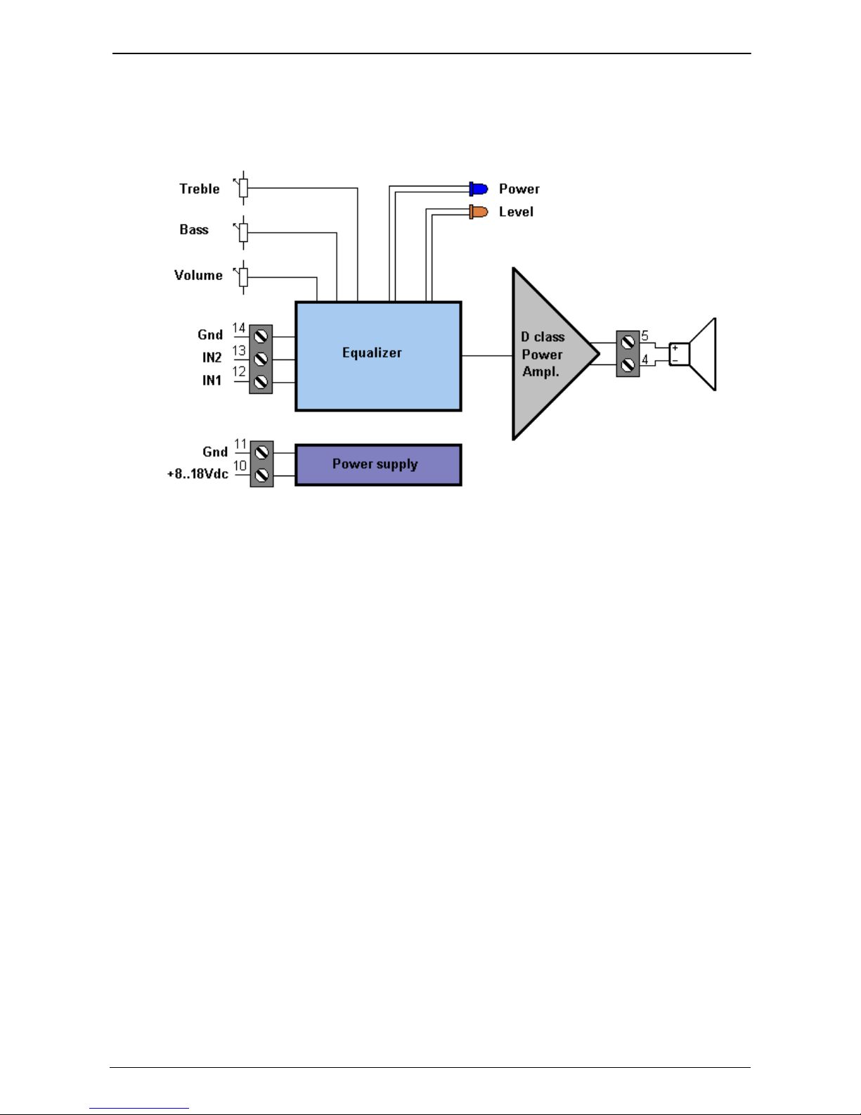
Please refer to the following block diagram of the device to describe the system.
The "Equalizer" block realized with analog technology manages the inputs, the tone controls, the
level signaling on the LED and passing the signals to the final stage of amplification, completely
digital, in D class.
The two signals on the two inputs are mixed together (with a common level control) so that a stereo source can also be correctly distributed.
There are two LEDs, "Power" indicating the powered system and "Level" which provides a visual
indication of the audio signal output to the speakers.
The Level LED flashes following the audio from when the output signal is approximately at -20dB
with respect to the maximum undistorted power (meaning about 10% distortion), it is steady for
signals around the maximum output level (probable 100% distortion).
It is also allowed a tone correction on the input signals to better adapt the audio to the acoustics of
the environment to be sounded.
Finally, the "Power supply" block supplies the internal circuitry correctly.
Page 8
TEMA TELECOMUNICAZIONI SRL
Audio Amplifier AD301R
MAS-AD301R-REV01EN Page 8 of 12
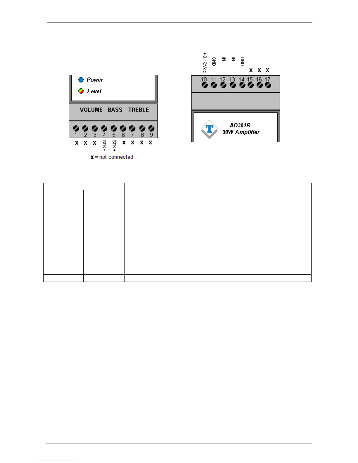
6. DESCRIPTION OF THE CONNECTION TERMINALS
TERMINAL
DESCRIPTION
4 SPK-
Negative speaker line
Usually the black wire of the cable to connect the speakers. *
5 SPK+
Positive speaker line
Usually the red wire of the cable to connect the speakers. *
10 + 8..18 VDC
Positive
power
supply
Positive supply voltage, values between 8 VDC and 18 VDC. **
11 GND
Negative power supply
/
ground
Negative supply voltage.
12 IN1
A
udio
1 input
(L) Input of
the
channel 1.
It is possible to connect a stereo source by connecting the L channel
here. ***
13 IN2
A
udio
2 input
(R) Input of
the channel 2
.
It is possible to connect a stereo source by connecting the R channel
here. ***
14 GND
Audio signal Ground
* Note. When using several speakers on the same line, it is essential to connect them all with the same polarity to avoid phase inversions that attenuate the reproduction of medium-low tones.
** Note. It is advisable to use the AA-39D3 power supply. It is possible to use the AA-39D1 power supply,
obtaining however half the nominal power, which can be compensated by using horn loudspeakers that
have greater efficiency and sound output. Both power supplies are stabilized ensuring absolutely no ripple
voltage that otherwise negatively affect quality sound reproduction.
*** Note. The playback will take place on the only SPK output in mono mode because AD301R will add the
channel L (IN1) and the R channel (IN2) input, ensuring the exact reproduction of the content of the stereo
source.
Page 9
TEMA TELECOMUNICAZIONI SRL
Audio Amplifier AD301R
MAS-AD301R-REV01EN Page 9 of 12
7. INSTALLATION EXAMPLES
7.1. Basic connection of the speakers 30W-4 Ohm
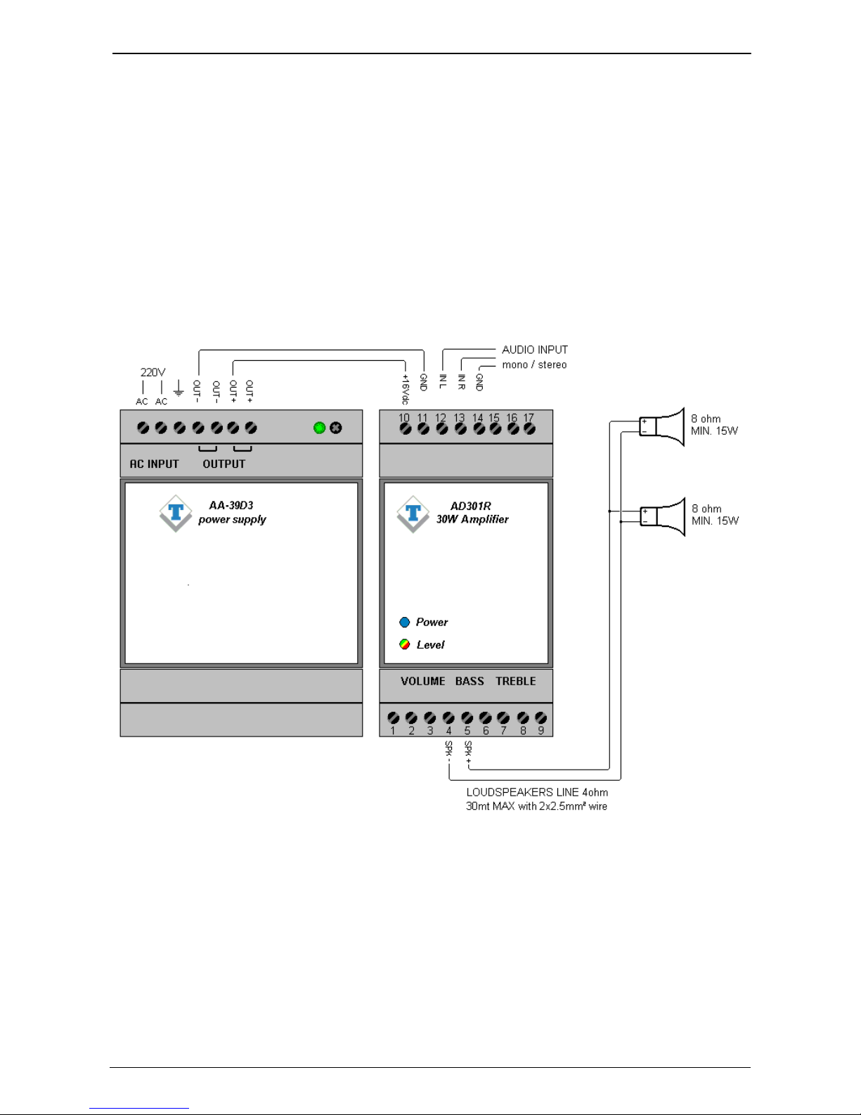
A simple first example of connection is the following.
In this case there are two speakers with 8Ω impedance connected in parallel and in the same
polarity to the SPK outputs of terminals 4 and 5. The system is powered by the AA-39D3 power
supply able to deliver a maximum current of 3.5A at 12VDC.
Note that the connection of the speakers in parallel (could be the model AD333/30T) reduces the
total impedance of the speaker system to 4Ω that however is perfectly suited to the output
impedance of AD301R by being able to take all the available power.
Page 10
TEMA TELECOMUNICAZIONI SRL
Audio Amplifier AD301R
MAS-AD301R-REV01EN Page 10 of 12
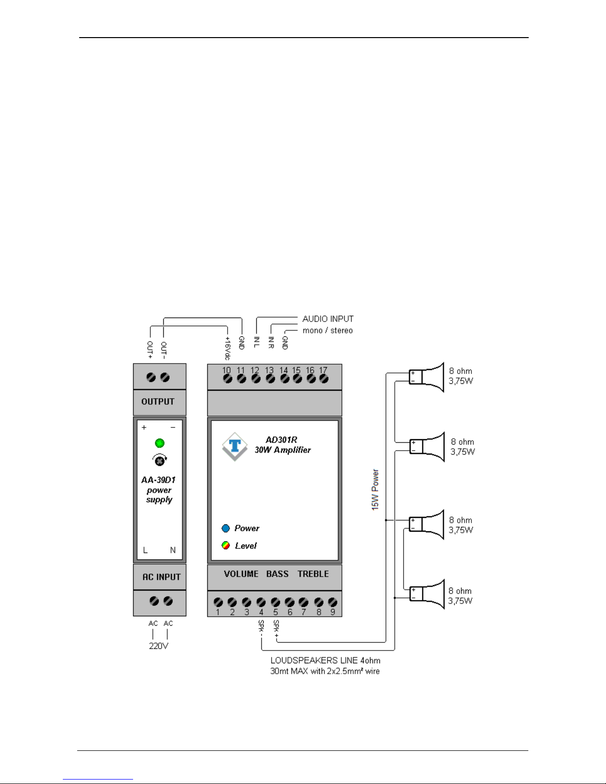
7.2. Basic connection with 4 horn speakers 15W-8 Ohm
It is possible to double the number of speakers compared to the previous example in order to have
a better sound distribution.
However, to comply with the characteristics of the minimum output impedance of the system
(minimum 4Ω) it is necessary to adopt a series/parallel connection of the speakers, it is not
possible to connect them all in parallel.
Keep in mind that if on one side the emitter surface increases (the number of speakers), on the
other the impedance obtained by the new connection mode does not allow to exploit all the power
that can be supplied by the amplifier but only half (in fact the impedance of the connected group
results at 8Ω).
To obtain a higher sound output, it might be advisable to use horn loudspeakers instead of
traditional models. The speakers could be the model AD330/15T.
Being in this case the power obtainable from the system limited to about 15W, it is possible to use
the AA-39D1 power s upply with a maximum current of 1.25A at 12VDC instead of the model AA-
39D3.
Page 11
TEMA TELECOMUNICAZIONI SRL
Audio Amplifier AD301R
MAS-AD301R-REV01EN Page 11 of 12
7.3. Basic connection with use of the AA-10/PA and AA-11/PA interfaces to send
announcement from telephone/PBX
An interesting application can be the use of the TEMA AA-10/PA or AA-11/PA interfaces as the
audio source, allowing to interface a telephone system with the paging sound system.
The simplest case is to connect an analog BCA telephone to the AA-10/PA system and at his
audio output is connected to AD301R. The operator can then spread warning messages in the
served area by the amplification system simply by lifting the phone handset and starting to speak.
Upon re-hooking, the message spreading will be released.
If a PABX is available, AA-10/PA must be connected to an analog trunk. In this case, the interface
will make it possible for all internal appropriately enabled users of the PBX, to spread a warning
message by engaging the line where AA-10/PA is connected and starting to speak. Upon rehooking, the message will be released.
If an internal analog extension of the PABX will be used instead of the analog trunk, the AA-11/PA
interface must be used. The operator can then broadcast warning messages in the area served by
the amplification system simply by calling the extension where the AA-11/PA interface is
connected and starting to speak. AA-11/PA does not generate any warning tone at the beginning
of the message output. When the handset is hung up, the message spread will be terminated after
the acknowledgment by AA-11/PA of the PBX reorder tone. The operator can also decide to
immediately terminate the call to AA-11/PA and then the announcement by dialing a specific
DTMF command.
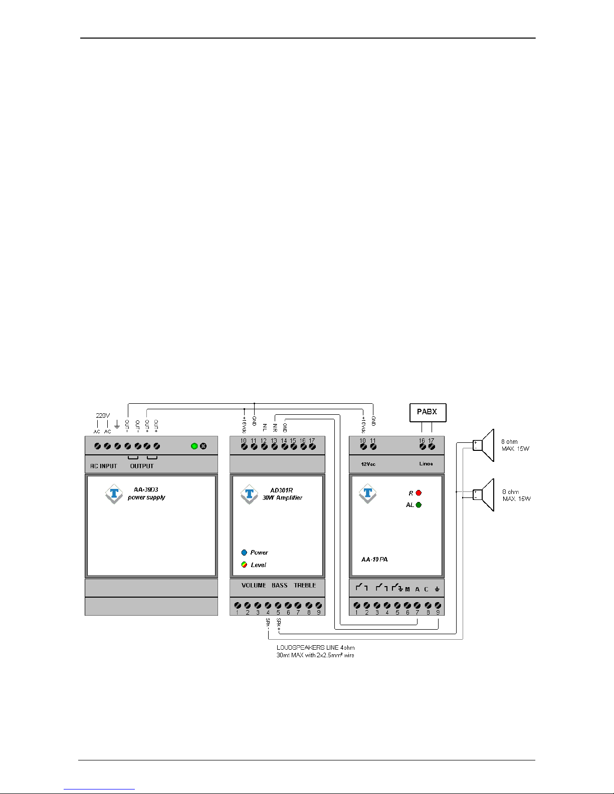
See the following diagram showing a typical AD301R connection with AA-10/PA connected to a
PABX analog trunk:
Page 12
TEMA TELECOMUNICAZIONI SRL
Audio Amplifier AD301R
MAS-AD301R-REV01EN Page 12 of 12
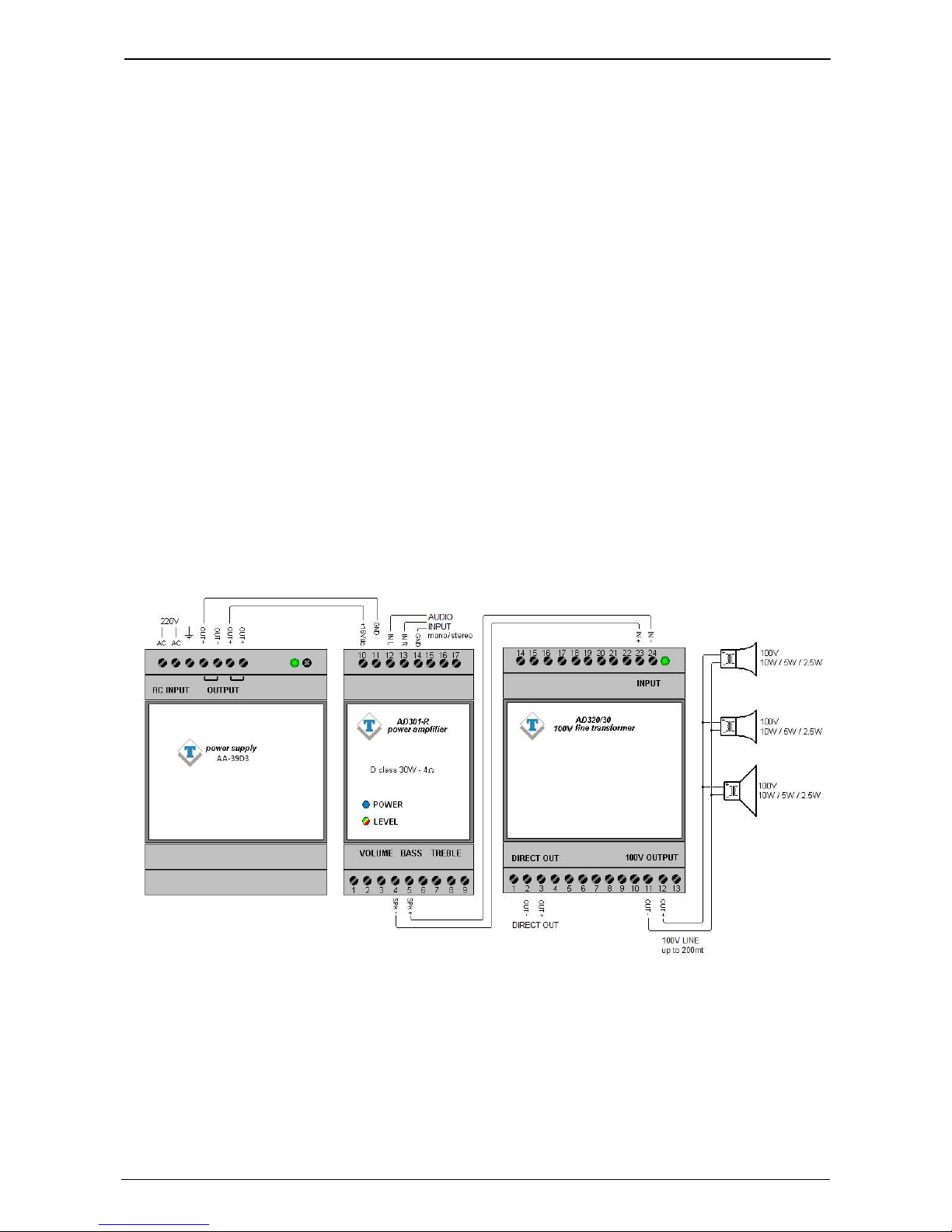
7.4. Connection with different power speakers on the 100V speaker line
This connection example uses the output transformer AD320/30 which allows to exceed the 30mt
limit of cable between the amplifier and the speakers suitable to be connected to the 100V line
such as horn loudspeakers AD330/15T and AD330/40T and the rectangular or round speakers
AD332/60T and AD333/30T.
In this case, the amplifier behaves as if it were a small power plant that supplied the 100V speaker
line.
Individual speakers will then determine how much power to take from the line. By connecting a 5W
speaker to the 100V line will be reached a certain sound intensity, using a 10W speaker will be
more power intensity.
All our loudspeakers are equipped with a commutator/selector or several connection terminals in
order to pick up different power levels from the line and adapt the sound intensity to the area that
has to be sounded.
The important thing is not to exceed the maximum power supplied by the amplifier in order not to
overload it. For example if speakers using the 10W socket are connected, it is not possible to
connect more than 3, but if the 5W socket is used then it is possible to connect up to 6.
It is also possible to use combinations, for example two speakers connected to 10W and two
speakers connected to 5W. Obviously the speakers connected to 5W will produce a lower sound
intensity.
 Loading...