

Page 1
Revision
Date
Revision reason
Prepared
Checked/Approved
4 21/02/2018 Update MM, GBC FL
MAS-AA560-REV04EN Page 1 of 65
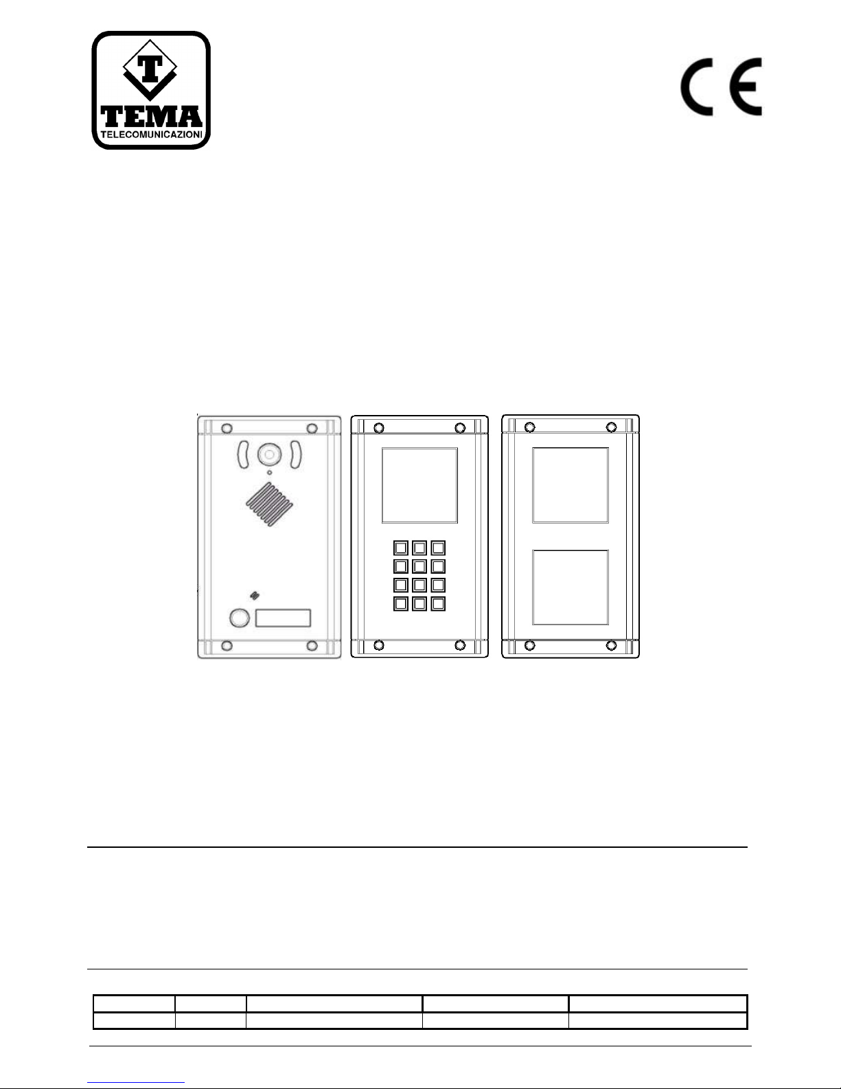
AA-560
VoIP SIP PoE Vandal Proof Stainless Steel
Intercom-Doorphone with 1 button
AA-539K additional keyboard module
AA-539R additional index module
TECHNICAL MANUAL – INSTALLATION
PRELIMINARY DOCUMENTATION
AA-560 System Manual – HW version 1.0 - SW version 1.08
Recommendations
1. Use only original spare parts and consumables supplied by Tema Telecomunicazioni Srl for this equipment. The company shall not be
held responsible for any damage caused by the use of materials that they have not supplied.
2. The device has been carefully manufactured and tested. In any case, the product is not recommended for use in situations in which
incorrect operating may result in damage to persons and/or property.
3. We recommend that you carefully read all this manual before starting to use the device.
4. Do not expose the device to sunlight and protect it from sources of heat, dust, humidity and chemical agents.
5. This manual is the property of Tema Telecomunicazioni Srl and any duplication and reproduction, even partial, as well as storage on
any type of media is forbidden without written permission from Tema Telecomunicazioni Srl.
Telecomunicazioni Srl.
TEMA TELECOMUNICAZIONI S.r.l.
Telecommunications - Electronics
Page 2

TEMA TELECOMUNICAZIONI SRL
Doorphone AA-560
MAS-AA560-REV04EN Page 2 of 65
We, TEMA TELECOMUNICAZIONI SRL Via C. Girardengo, 1/4 - 20161 MILANO
declare under our sole responsibility that the product:
product name Cito telefono - IP SIP VoIP PoE - Doorphone
trade name TEMA TELECOMUNICAZIONI Srl
type or model AA-560, AA-560C
and accessories AA-539K, AA-539R
to which this declaration relates is in conformity with the essential requirements and other
relevant requirements of the R&TTE Directive ( 1999/5/EC, 2006/95/EC, 2004/108/EC ).
The product is in conformity with the followings standards and/or other normative documents:
HEALT & SAFETY EN 60950-1:2006
+A11:2009
+A1:2010
+A12:2011
EMC EN 55022:2010
EN 55024:2010
EN 61000-3-2:2006
EN 61000-3-3 :2008
MILANO, 07 April 2014 TEMA TELECOMUNICAZIONI SRL
D. Pontillo
DECLARATION OF CONFORMITY (DoC)
Page 3
TEMA TELECOMUNICAZIONI SRL
Doorphone AA-560
MAS-AA560-REV04EN Page 3 of 65
I.
IMPORTANT INFORMATIONS REGARDING THE RECOVERY AND RECYCLING OF THIS
ELECTRONIC DEVICE
The crossed-out wheeled bin symbol below indicates that this electronic equipment is intended to be disposed in a
separate collection and not in an unsorted municipal waste, in order to provide for the treatment of WEEE (Waste
Electrical and Electronic Equipment) using best available recovery and recycling techniques.
Specific treatment for WEEE is indispensable in order to avoid the dispersion of pollutants and other hazardous
substances into the waste stream, while recycling leads to reduction of disposal of waste and the negative impacts
on environment and human health. That is, priority is given to reuse of WEEE in its components, subassemblies
and consumables.
As the final holder, the user has an important role in contributing to reuse, recycling and other forms of recovery of
WEEE and is responsible to return this waste in the collection facilities set up by EC Member Stases and to fulfill
other duties in compliance with Directive 2002/96/EC and local laws.
Page 4

TEMA TELECOMUNICAZIONI SRL
Doorphone AA-560
MAS-AA560-REV04EN Page 4 of 65
1. INTRODUCTION .............................................................................................................................. 6
2. MAIN FEATURES ............................................................................................................................ 7
3. PARTS COMPRISING THE SYSTEM (PACKING LIST) .............................................................. 8
3.1. C
ROSS-REFERENCE TABLE OF FEATURES / SERVICES OF THE VARIOUS MODELS
....................................9
4. TECHNICAL SPECIFICATIONS .................................................................................................. 10
5. OPERATION ................................................................................................................................... 12
5.1. N
UMERIC KEYPAD EXPANSIONS
..................................................................................................... 12
5.2. D
EVICE DIAGRAM
......................................................................................................................... 13
6. OPERATING MODES .................................................................................................................... 14
6.1. DAY / NIGHT / INTERVAL
MODES
............................................................................................... 14
6.2. A
DDITIONAL FEATURES OF THE KEYPAD EXPANSION
......................................................................... 14
6.3. RELAYS
CONTROL WITH ACCESS CODES
....................................................................................... 15
6.4. C
ALLS GENERATED FROM
AA-560 ................................................................................................. 15
6.5. C
ALLS TO
AA-560 ....................................................................................................................... 16
6.6. A
CQUISITION OF EXTERNAL CONTACTS FOR SPECIAL APPLICATIONS
................................................... 16
6.7. M
ULTICAST A UDIO STREAMING
...................................................................................................... 17
7. COMMANDS AND CODES FOR THE INTERNAL OPERATOR ............................................... 18
7.1. S
IGNALING LED AND
AA-560
FRONT PANEL DESCRIPTION
................................................................ 19
8. INSTALLATION ............................................................................................................................. 20
8.1. I
NSTALLATION OF SYSTEMS
........................................................................................................... 20
8.2. I
NSERTING OR REPLACING THE NAMES ASSOCIATED WITH THE BUTTONS AND LEGEND LABELS
.............. 23
8.3. CONNECTIONS ........................................................................................................................ 24
8.3.1. C
ONNECTION OF THE BASE SYSTEM
AA-560 ................................................................................... 24
8.3.2. C
ONNECTING THE SYSTEM EXPANSION
AA-539K ............................................................................ 25
8.3.3. C
ONNECTING THE SYSTEM EXPANSION
AA-539R ............................................................................ 26
8.4. D
ESCRIP TION OF THE TERMINAL BLOCKS OF RELAYS
........................................................................ 27
8.5. D
ESCRIP TION AND EXAMPLES OF OPERATION MODES WITH THE INTERNAL RELAYS, CONNECTIONS
........ 28
8.5.1. CASE 1 –
DRIVE OF TWO ELECTRIC LOCKS WITH SYSTEM POWERED
.................................................. 28
8.5.2. CASE 2 –
DRIVE OF TWO ELECTRIC LOCKS, SYSTEM POE POWERED, ONE POWER SUPPLY
.................. 29
8.5.3. CASE 3 –
DRIVE OF TWO ELECTRIC LOCKS WITH SYSTEM POWERED WITH 3 DIFFERENT POWER SUPPLIES
30
8.5.4. CASE 4 –
DRIVE OF TWO ELECTRIC LOCKS, SYSTEM POE POWERED, TWO SEPARATE POWER SUPPLIES
31
8.5.5. CASE 5 –
DRIVE OF AN ELECTRIC LOCK AND AN OPENING BUZZER
..................................................... 32
8.5.6. I
NPUT C ONNECTIONS
.................................................................................................................... 33
8.5.7. C
ONNECTION BETW EEN BASE UNIT AND EXPANSIONS
....................................................................... 34
8.5.8. C
ONNECTING
AA-539R
MODULES IN CASCADE STARTING FROM A
AA-560
BASE MODULE
.................... 35
8.5.9. C
ONNECTING
AA-539R
MODULES IN CASCADE STARTING FROM A
AA-539R
POWERED MODULE
.......... 35
9. PROGRAMMING ........................................................................................................................... 36
9.1. P
REPARING FOR PROGRAMMING SYSTEM PARAMETERS
.................................................................... 36
9.2. A
CCESS TO PROGRAMMING AND RESET ADDRESS AND PASSWORD
.................................................... 38
9.3. N
ETWORK PARAMETERS
............................................................................................................... 39
9.4. SIP
PARAMETERS
........................................................................................................................ 40
9.5. G
ENERAL PARAMETERS
................................................................................................................ 41
9.6. S
ET OF THE OPERATING MODE
....................................................................................................... 43
9.7. R
ELAY AND INPUT SETTINGS
.......................................................................................................... 44
9.8. C
AMERA
..................................................................................................................................... 46
9.9. C
ALL BUTTONS
............................................................................................................................ 47
9.10. M
ESSAGES MANAGEMENT
............................................................................................................. 49
9.11. A
UTOMATIC ANNOUNCEMENTS
...................................................................................................... 51
9.12. RFID
MANAGEMENT
..................................................................................................................... 53
Pag.
Page 5

TEMA TELECOMUNICAZIONI SRL
Doorphone AA-560
MAS-AA560-REV04EN Page 5 of 65
9.13. C
ALLS REPORT
............................................................................................................................ 53
10. MAINTENANCE ............................................................................................................................. 54
10.1. S
YSTEM
...................................................................................................................................... 54
10.2. L
OGIN CREDENTIALS
.................................................................................................................... 55
10.3. D
IAGNOSTIC LOG
......................................................................................................................... 55
11. PRESENTATION AND USE OF THE PROGRAM "AA V
IDEO CONSOLE
" ................................ 56
11.1. P
RESENTATION
............................................................................................................................ 56
11.2. S
OFTW ARE CONFIGURATION FOR
SIP S
ERVER MODE
....................................................................... 57
11.3. S
OFTW ARE CONFIGURATION FOR PEER-TO-PEER MODE
.................................................................. 58
12. INFORMATIONS FOR THE WALL INSTALLATION OF THE SYSTEMS ................................ 59
Page 6
TEMA TELECOMUNICAZIONI SRL
Doorphone AA-560
MAS-AA560-REV04EN Page 6 of 65
1. INTRODUCTION
The AA-560 is a Doorphone that can be connected to any VoIP SIP PBX, as a SIP extension, with the possibility of
power either through dedicated external power adapter, or through PoE on the LAN. Alternatively it is possible to
be used in a Peer-to-Peer connection and allows the opening of one or two electric locks (two integrated relays).
The series AA-560 differs from the AA-550 series for its stainless steel container and is ideal for applications in
civil, industrial and heavy-duty environments.
AA-560 is installed for example on a gate for external control and when a visitor presses the button to show up,
make a VoIP phone call to the number of the operator, allowing audio communication.
In addition, thanks to the integrated color camera with Led lights (version AA-560C), it is possible to see the visitor
directly to the operator's internal IP video phone or on the screen of his PC with a standard internet browser,
ensuring the maximum security of the framed area. Having the possibility to monitor the area with the integrated
camera, AA-560 can be called directly from an extension phone to communicate with any visitor and/or to control
the opening of the controlled gates, without any visitor request for access. Once it is established that the visitor
must enter into the company, the operator may open directly from his phone, with a DTMF tones code, the electric
gate or pedestrian gate.
AA-560 can be programmed with a web interface reachable from any PC connected to the corporate LAN, using a
common web browser by typing the IP address of the device.
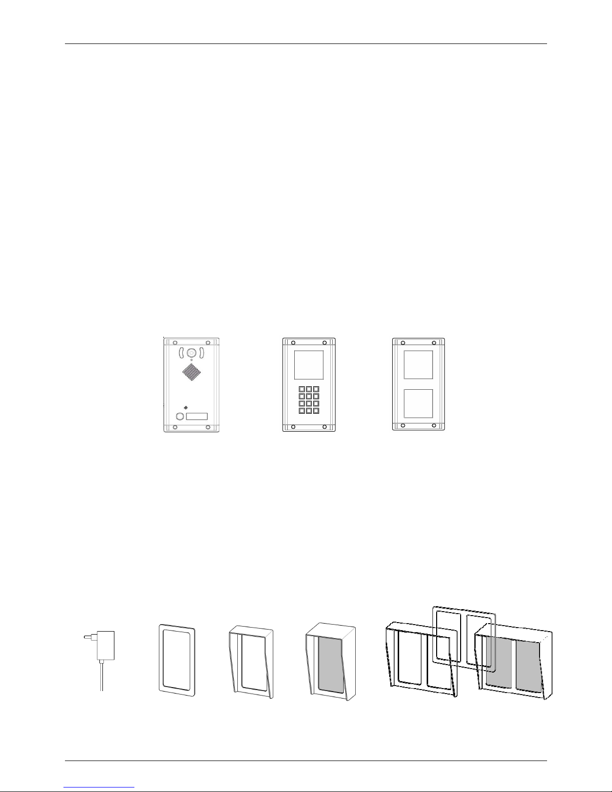
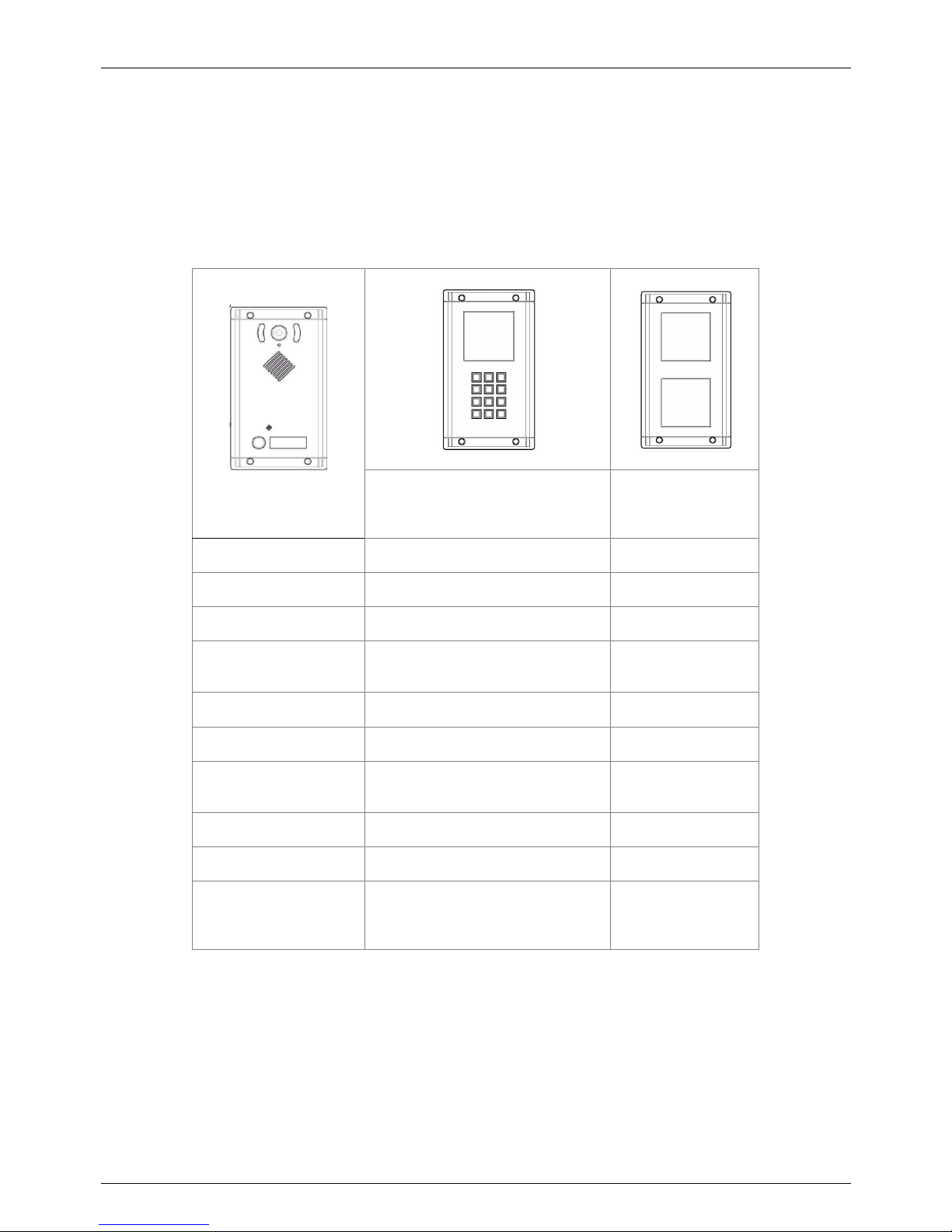
AA-560 AA-539K AA-539R
The units are equipped with one or two relays to control the door opener. The Doorphone can be called directly
from an extension to activate the opening of the controlled gate even without the request for access from an
outside visitor or to be programmed. The base system is available with 1 button. There is an expansion module AA539K with full numerical keyboard and an index window zone, to expand the services offered by the system and
give way to the visitor to directly dial the numbers.
Among the expansions is also available the AA-539R module, which is useful in conjunction with the keypad, with
two wide backlit surface to be used to present to the visitor a complete legend of numbers to dial. AA-539R can
also be used to provide more general informations such as the civic number etc. These modules can be added at
will, depending on the amount of information to be presented to the visitor.
Completing the series of systems: wall frames, rain shields, external wall boxes and a power supply.
AA-39 AA-549-C1 AA-549-T1 AA-549-S1 . . .
Page 7

TEMA TELECOMUNICAZIONI SRL
Doorphone AA-560
MAS-AA560-REV04EN Page 7 of 65
2. MAIN FEATURES
Generals
•
Make a VoIP phone call after the press of a button on the device
•
Programming via Web interface with password protection
•
Operation modes Day / Night / Interval (with manual or automatic mode) for different numbers of call
destination
•
Two door opener relays for possibility of activation of a second electric lock, for example to make the
distinction between pedestrian gate and driveway gate
•
3 optocoupled inputs for signals/events external acquisition
•
Up to 6 programmable codes (3 for each relay associated with electric lock) to drive the relay directly from
the door without the intervention of the operator
•
Setting the operation mode Day / Night / Interval via telephone or in automatic (time slots), retention of the
settings also after a power failure
•
Backlight of the key label holder and integrated internal anti-humidity heating system
•
Great versatility and ease of use and programming
•
Hands-free talking with high audio quality
•
Possibility to upgrade the software via LAN
•
Possibility to acquire up to 6 external contacts to the system and warning service with dedicated messages
•
Possibility of receiving and sending MULTICAST RTP audio streaming, for paging audio announcements, up
to 16 priority levels (in reception) and with different volumes for each channel
•
Possibility to receive and send RTP MULTICAST audio streaming, for paging announce, up to 5 receive
priority leves
•
Possibility to activate a second SIP account, used for “Night ringer” group
•
Possibility to protect the audio connection for incoming calls with a code (monitor)
•
“Push-to-talk” function, using any input
•
“Opendoor” function”, using any input
•
Audio streaming with high quality codecs
•
Possibility of diffusing pre-recorded announcements at pre-established times (up to 5 for each day of the
week)
•
Possibility of diffusing a pre-recorded daily announcement, at a set time or manually controlled, with
programmable interval and repetitions
•
Possibility to play a prerecorded announcement message, with a telephone code or using any input
VoIP IP LAN section
•
Integration with the local LAN, 100 BaseT Ethernet port with RJ45 connector
•
SIP-based VoIP connection in either SIP Proxy Server or Peer-to-Peer mode, PoE (Power over Ethernet)
possibility
•
Up to 2 programmable numbers are available by each button, with possibility of supervisor and call cycles;
ability to associate a SIP extension number or an IP address, according to the connection mode SIP Proxy
Server or Peer-to-Peer
Integrated color camera (only version AA-560C)
•
Integrated color camera
•
Video Streaming over IP phone with video support, or on a PC using a web browser, or using the supplied
software "AA Video Console”
•
Image storing: snap photos when the call button is pressed by the visitor, with the possibility of sending the
same email in real time
Page 8
TEMA TELECOMUNICAZIONI SRL
Doorphone AA-560
MAS-AA560-REV04EN Page 8 of 65
3. PARTS COMPRISING THE SYSTEM (PACKING LIST)
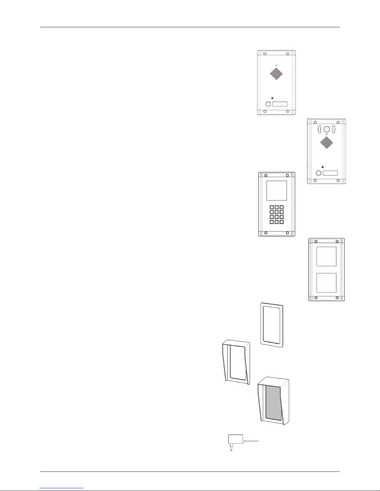
AA-560 system consists of the parts included in the following list:
• An AA-560 device (external unit with 1 buttons)
• A special key for the front panel screws
• A set of die cut labels with extractor for label holders
• A CD-ROM with documentation and technical manual
AA-560C system consists of the parts included in the following list:
• An AA-560C device (external unit with 1 button + camera)
• A special key for the front panel screws
• A set of die cut labels with extractor for label holders
• A CD-ROM with documentation and technical manual
AA-539K expansion consists of the parts included in the following list:
• An AA-539K module (full numeric keypad)
• Cable for connection to the base unit AA-539
• A special key for the front panel screws
AA-539R expansion consists of the parts included in the following list:
• An AA-539R module (Legend)
• A special key for the front panel screws
• One die cut label for the index legend (already inserted in the system)
It is possible to equip the series of systems also with the following accessories:
Frames for wall covering
for one, two or three devices respectively
AA-549-C1, AA-549-C2, AA-549-C3
Frames for wall covering and flush box
for one, two or three devices respectively
AA-549-T1, AA-549-T2, AA-549-T3
Complete box for external wall mounting with
rain shield for one, two or three devices respectively
AA-549-S1, AA-549-S2, AA-549-S3
Power supply adapter AA-39AL
Page 9
TEMA TELECOMUNICAZIONI SRL
Doorphone AA-560
MAS-AA560-REV04EN Page 9 of 65
3.1. Cross-reference table of features / services of the various models
At any base model AA-560 and AA-560C, it is possible to add one expansion module AA-539K while it is possible
to add more AA-539R modules.
The keyboard module is AA-539K with metal backlighted keyboard.
The expansions AA-539K is connected and powered directly from the base unit via a supplied cable, expanding the
functions of the base system:
Expansion
AA-539K
Expansion
AA-539R
Numbers of buttons
-- --
Telephone Keypad
Yes --
Door opening codes
Yes --
Button matching to the
phone number
Yes (keys from 1 to 9) --
Direct number dialing
Yes --
Speed dial
Yes --
Possibility of filter/prefix
digits
Yes --
Backlighting
Yes legend and keyboard Yes
Label holder
-- Yes, front area
Additional front area
for informations with
backlight
Yes Yes
Page 10

TEMA TELECOMUNICAZIONI SRL
Doorphone AA-560
MAS-AA560-REV04EN Page 10 of 65
4. TECHNICAL SPECIFICATIONS
Generals
Buttons
One button with backlighted label holder
Internal heating
Anti-humiditiy internal heating circuit
Audio section
Internal speaker with RMS power 1.3W
Possibility of adding an external speaker, RMS power of 1.3W
and minimum impedance 8Ω.
Insertio
n type terminals for relays
and other
Possibility to use cables up to 1.5mm
2
or AWG16
Number of built
-
in relays
2
Max relay contacts load
Fino a 2A
- 30V
Power Supply
12VDC
/ VAC, 800mA max di assorbimento
Power Supply of additional systems
Powered fr
om the base system using the supplied cable:
AA-539K backlight circuit max. 250 mAAC
AA-539K anti-condensation circuit max. 310 mAAC
AA-539R backlight circuit max. 250 mAAC
AA-539R anti-condensation circuit max. 310 mA
AC
Difference of potential betwe
en 3
power sources that can be
connected to AA-560
(system - relay 1 - relay2)
1500V
Material of the container
INOX steel 316L
Steel button
Mounting type
Flush mounting, wall mounting with accessory AA
-
549-S
IP grade of protection
IP66 (with system cor
rectly installed)
Operating Temperature
From
-20˚C to +50˚C
Relative humidity
95% not
-
condensing
Systems dimensions and weight
AA-
539
L 123 x H 218 x D 14 (+44) mm
- 1100 g
AA-539C L 123 x H 218 x D 14 (+44) mm - 1175 g
AA-539K L 123 x H 218 x D 14 (+44) mm - 1100 g
AA-539R L 123 x H 218 x D 14 (+44) mm - 1100 g
(dimensions of the flush part into the wall)
Accessories for mounting and security of the systems
Dimensions and weight
AA-
549-C1 L 138 x H 230 x D 2 mm
- 070 g
AA-549-C2 L 262 x H 230 x D 2 mm
- 125 g
AA-549-C3 L 386 x H 230 x D 2 mm
- 175 g
AA-549-T1 L 141 x H 231 x D 43 mm
- 240 g
AA-549-T2 L 265 x H 231 x D 43 mm
- 330 g
AA-549-T3 L 389 x H 231 x D 43 mm
- 470 g
AA-549-S1 L 141 x H 231 x D 90 mm
- 0740 g
AA-549-S2 L 265 x H 231 x D 90
mm -
1250 g
AA-549-S3 L 389 x H 231 x D 90 mm
- 1740 g
Page 11
TEMA TELECOMUNICAZIONI SRL
Doorphone AA-560
MAS-AA560-REV04EN Page 11 of 65
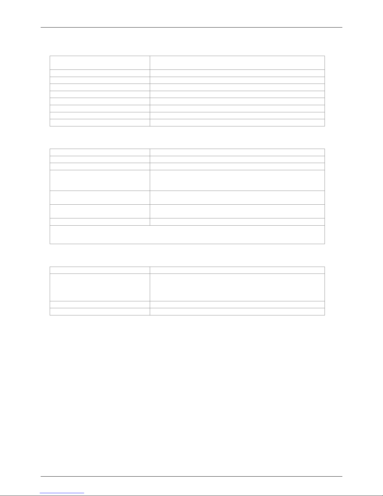
VoIP
PoE power supply
According to IEEE 802.3af
(only for system powering, not for opening electric lock)
LAN Ethernet LAN 100 BaseT port
Supported VoIP Protocols
SIP v2
Supported con
necting modes
SIP Server or Peer
-to-
Peer
Protocols
IP, TCP, UDP, http, TELNET, SIP, RTP
Bandwidth
300 –
3400 Hz
Audio codec
G711µ, G711a, G722,
16-24-32 kHz
Echo soppressor
Yes
MULTICAST
RTP streaming audio
Yes
Inputs contacts
Insertion t
ype terminals for input
Possibility of use of cables up to 1.5 mm
2
or AWG16
Number of inputs
3 distinct with common terminal connector
Number of optoisolated inputs
3 distinct with common terminal connector, 1500V
Type of drive
For each input, acquisiti
on of a voltage
-
free contact for
connection between the individual input and the common point of
the dedicated connector (TB5 pin 3,4,5,6 and TB6)
Time for change state detection
Closing or opening of the stable external contact for at least 100
milliseconds, any less time trigger will be ignored
Voltage for detection state contacts
12VDC max, the system has its internal voltage reference to
detect contact closure
Current for detection state contacts
Max 10 mA, with the closed contact to the common poin
t
Note:
it is not possible to apply any voltage at the terminal points dedicated to the acquisition of the inputs state
(TB5 pin 3,4,5,6 and TB6), because it will damage the system
Note: the individual inputs (including the common point) are not galvanically isolated from each other
Integrated Camera (only AA-560C version)
Type
Color camera
Video resolution
640 x 480
352 x 288
320 x 240
176 x 144
View angle
70°
Video output
IP Video streaming, H.263, H.263+
, H264
Page 12

TEMA TELECOMUNICAZIONI SRL
Doorphone AA-560
MAS-AA560-REV04EN Page 12 of 65
5. OPERATION
When the call button in idle mode is pressed, AA-560 automatically generates a telephone call through the VoIP
PBX. The visitor begins to listen to the speaker of AA-560 the outcome of his request for access, or listen to the
ringing tone and the subsequent reply by the operator that was called.
Optionally, before forwarding the call, it is possible to set a message playing (matched to each key and each
mode), such as "The company is closed, wait for the reply from the operator...".
The operator who asnwers to the visitor can immediately decide to activate the electric lock directly typing the
correct sequence of programmed DTMF digits codes (opening the door), and hang up when finished. When the
user hangs up, AA-560 will return to the idle state recognizing the closing and will be ready for a new access
request.
It is also possible for the operator or other extensions to call the phone number where AA-560 is connected to
reach the Doorphone, to speak with people close to the entrance and to activate the electric lock without waiting for
a visitor call. It is also possible to protect this feature with a connection/listening code.
It is possible to adjust the audio level of AA-560 in order to better adapt to the acoustic characteristics of the area
where it is installed.
With the AA-560C version, which has an integrated color camera, it is possible to see the framed area. The video
of the camera is carried on an IP Stream directly on the corporate LAN using the same LAN cable for connecting
AA-560C. It is possible to see the framed area on an IP phone with video capability or directly to a PC via a
standard browser.
5.1. Numeric keypad expansions
Adding the AA-539K expansion it is possible to have the telephone keypad that allows some additional services .
There is for example the possibility for the visitor to directly call a phone number, or to call the numbers
(appropriately pre-programmed in the parameters) of the Speed Dial operating.
See for example the case of a possible visitor who goes to the entrance of a buildi ng site and among the dozens of
companies on the job site must conctat one in particular: just provide a legend in the proximityy of the device that
has the instructions and the various numbers to call to get in touch with the person of each company.
The same operation mode may be applicable in public facilities, large buildings and other environments. The calls
(if allowed by the appropriate class of service of the extension number assigned to AA-560 on the PBX) can also
be made to mobile phones or trunks and not only just to the extensions of PBX to which it is connected.
It is also possible to dial only the final part of the number using the operation mode with a root number. In this case
the system prepends to the dialed number on the keypad a pre-programmed prefix. For example, if the root
number is "3" and the user types on the keyboard "14", the system will associate the prefix and dial the number
"314". This service is also found useful to mask the true extension number of the person to contact.
In addition, this field or service may be used to avoid to make calls directly from the system, when equipped with a
AA-539K keypad, engaging the external lines of the connected PBX. In fact, if a visitor will try to make dial
02123456, the system will call 302-123456 preventing the external call.
The direct dialing mode is NOT an alternative to the speed dialing mode and can both work.
Page 13
TEMA TELECOMUNICAZIONI SRL
Doorphone AA-560
MAS-AA560-REV04EN Page 13 of 65
5.2. Device diagram
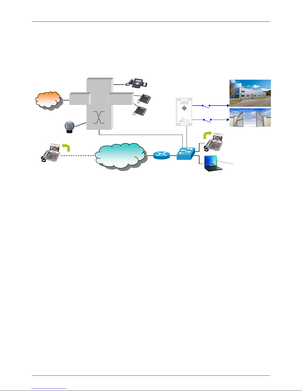
The AA-560 Doorphone is connected to the PBX via the LAN RJ-45 port. The contacts of relays will be used to
drive an electric door opener and/or a light at the entrance, a gate for pedestrian and/or the driveway gate.
The figure below shows an example of Doorphone connection:
Description of the new features made available by installing AA-560 in the company:
•
The visitor that press one of the Doorphone buttons will be put in contact with the operator who may decide
to open the electric lock from his telephone and give way to access the company. In the same way he may
decide to open the driveway gate to give access to a vehicle.
•
The operator who has been able to monitor the video in the area, can directly operate the two possible
access gates, without waiting for the visitor to press the buttons on the Doorphone.
•
During the Night mode, when the operator is no longer present in the company, the call generated by the
Doorphone can be forwarded to a telephone number of a guardian that could open the gates and let the
visitor to access by acting the relays even remotely (eg. being reached with a call to his mobile phone).
•
The two integrated relays could be used, in another case, one for the gate and the second to activate a
lighting system of the entrance area, to be activated only when there is a transit of persons or vehicles.
Extensions
IP
PBX
PO
PSTN
Line
Trunks
General
call
ringer
2
INTEGRATED
RELAYS
INTERNET
LAN
Switch
PoE
Doorphone
VoIP
AA-560
PC
Extensions
SoftPhone
Audio/video
IP
Phone
Gateway
Router
IP Phone
Page 14

TEMA TELECOMUNICAZIONI SRL
Doorphone AA-560
MAS-AA560-REV04EN Page 14 of 65
6. OPERATING MODES
The system has the label holder combined with the button. When a visitor presses the button, the system make a
call on a PBX extension associated with the pressed button.
The numbers that are called may differ depending on the operating mode in which the system is programmed,
Day - Night mode / Interval mode, (see par. 9.6).
In the case of keyboard expansion, are valid the same informations as stated for the buttons on the base system
while the keyboard allows to dial the desired number, or to handle additional functions described later.
If is used the keyboard in Speed Dial mode, described below, the descriptions of the operating modes listed below
are valid only for the numbers associated with the Speed Dial service.
Finally, there are 3 optocoupled inputs whose operation is described below.
6.1. DAY / NIGHT / INTERVAL modes
In each of the three possible operating modes, the system makes a call to a number after pressing a button (or call
to two numbers if also the second number is programmed) for a configurable number of times. It is also possible to
specify an additional final number, called the "supervisor", to contact at the end of the previous programmed
attempts. The call is considered successful when the operator answers.
The visitor hears the signalings of the current call preceded by a greeting voice message, when enabled.
If the visitor presses a button again while the call is in progress, the system stops the call and returns to standby.
For the systems with the keyboard expansion you must press the star key (*) to stop the call.
The system can be manually placed in a Day, Night or Interval (the operator will send a special command to the
system), or it can automatically switch to each mode according to a time schedule.
The active mode is stored also when the system is powered off and then reactivated when it will be powered on.
6.2. Additional features of the keypad expansion
If the expansion module AA-539K is installed, the visitor can make a call simply by dialing the desired number if
known by hi m or made into an index table placed near the Doorphone (eg the AA-539R expansion), typing it
directly on the keyboard.
The introduced numbering is considered finished after about two seconds of entering the last digit by the visitor. It
is possible to speed up the dialing without waiting for the system timeout by pressing the pound key (#) at the end
of the number, in which case the call is made immediately.
The visitor, realizing that has made mistakes in typing can be immediately cancel the entered digits by pressing the
star key (*), the same key has the function to break down if the call already in progress.
In addition to direct dialing mode, the keypad allows for Speed Dial function, in which it is possible to associate a
number to call to each digit of the keyboard (10 phone numbers associated with the digits from 0 to 9, see par. 9.9),
with the possibility to differentiate between Day, Night and Interval.
According to the system mode, the visitor can then contact one of the 30 numbers entered. The Speed Dial mode
is NOT exclusive but coexist with the possibility of direct dialing with the only exception that it is not possible to
directly dial single digit numbers. Having to select the visitor directly to a single-digit numbers it is not possible to
use the Speed Dial service.
The Speed Dial feature (single digit of the keyboard) behaves as pressing a button on the base system and
behaves in effect as pressing a button on the base system with the only difference that it is possible to set only one
number for each selection. In practice, for the user, the keyboard also adds 10 more call buttons.
By directly dialing the number to call on the keyboard, may be possible for the visitor to dial a number that you do
not want to be dialed, or at least reached (eg outside the company). To avoid this possibility it is possible to use a
prefix before the number to be dialed. If the numbers of operators are in the numbering plan of the PBX (internal
extensions), it is sufficient to program the parameter with the first digit of the numbering plan and expose the
Page 15

TEMA TELECOMUNICAZIONI SRL
Doorphone AA-560
MAS-AA560-REV04EN Page 15 of 65
legend for visitors with numbers to reach without the first digit. For example, to call the operator at the extension
number 311 it must be programmed the prefix with a value of 3 and indicate to the caller to dial the number 11.
In the case there is the need that the the visitor must dial external numbers, this parameter may be useful if filled
with the value of a code that instructs the PBX to use a specific trunk group for outgoing governed by the desired
class of service, with restrictions on certain numbers for calls when the PBX allows it (long distance calls, foreign
calls, fee-based services, mobile network, etc.).
In other cases, remember to activate some kind of control on the possible numbers that a general visitor can dial to
prevent unauthorized calls.
AA-560 is equipped with a special table of up to 60 characters that allows to create a filter on the selections made
by the user, in order to allow or reject it, even without the control of the PBX. This table and this service are very
useful for systems equipped with the full keyboard expansion module.
6.3. RELAYS control with access codes
The opening function of the door opener connected to the two relays can be made available to a visitor who is
familiar with the various preset access codes.
Since the system have only one button is advides to use this function only with AA-539K expansion because with
only one button available is possible to obtain a unique code simply composed by a sequence of digit 1 (max 5
digit). If you want to still use the function without the AA-539K expansion, it is possible to assign only one code. In
fact in this case the only values that the code can have are 11, 111, 1111, 11111. It is possible to set up to three
access codes for each relay, one for the Day mode, one for Night mode and one for the Interval mode (see par.
9.7). Upon the detection of the correctly inserted code, the corresponding relay will be activated for the time set in
the parameter.
If instead the system uses the AA- 539K expansion, the opening codes must be typed directly on the keyboard
preceded by the star key (*) to distinguish them from a normal telephone call. The visitor will get access without
operator intervention (for example, useful to service personnel or external assistance, which for work reasons
comes out and log back frequently in the company).
Relays can be also actuated with any of input signals (for example it is possible to connect an internally installed
push button for exit), see in the “Alarms – Inputs setting” programming mask the “Call” field.
6.4. Calls generated from AA-560
These are the calls that the system generates on the line, triggered by the pressure of the button by a visitor by the
previously described ways.
Who answers the call can speak to the caller for a fixed time set in the general parameters (see. par. 9.5). If the
conversation goes on, warning tones will be played in the phone so that the operator can enter the code “#5” to
extend the call duration.
Also during the conversation, the operator can enter a code to open the door (see. par. 9.5). Once the door was
opened, the conversation may be closed or not, according to the programming of the relay. If it is configured so that
the call is not closed, it will remain active until the timeout expires or, if the operator hangs up, the system will return
immediately in standby mode.
Page 16

TEMA TELECOMUNICAZIONI SRL
Doorphone AA-560
MAS-AA560-REV04EN Page 16 of 65
6.5. Calls to AA-560
Call the system AA-560 from the PBX phones is useful to activate the conversation or issue commands for
example when a visitor is detected near the Doorphone, through a video surveillance system of the gate, or if some
vehicle arrived at the entrance driveway or as announcer to serve certain areas of warehouses without using a
more complex system of public address audio diffusion.
Calling the extension number connected to the AA-560 system, it will answer after a preset time. In conversation
the caller has the same commands described above for incoming calls to trigger the door opening and other
controls such as the change of the operating mode, and more.
It is possible to set the reply of the system by pressing a button of the Doorphone. This service, governed by
general parameters (see. par. 9.5), allows to avoid an undesired conversation in the absence of an interlocutor.
It is also possible to connect the audio of incoming calls only after the user enter an access code, for example if the
device is installed in protected environments.
6.6. Acquisition of external contacts for special applications
AA-560 has the ability to monitor and acquire the status of external 6 contacts to make reports (3 optoisolated),
indipendent from the normal operation as Doorphone. In the following descriptions of the services associated with
the acquisition of these external contacts, will be used the generic "alarms" word.
For each available input, it is possbile to associate a phone number or an IP address that will be called when the
input is triggered. AA-560 has a maximum of three separate inputs of the acquisition, and then up to three different
numbers. The programming of the inputs is described in par. 9.7. It is possible, for each input, to set the condition
of activation of the same
Normally, the closing of an external contact connected to the corresponding input will start the sequence of
signaling but it is also possible to reverse this logic, so the signaling can be done following t he opening of the
contact connected to the input.
AA-560 continuously monitors the status of three contacts and the alarm condition is stored in a non-volatile
memory. As soon as possible it begins to call the person who will have to manage the alarm situation and plays the
message associated with the relative input (see par. 9.10). It is also possible to play a prerecorded message,
reproduced before making the call.
For each input, it is possible to define a code acquisition / acknowledgment of the alarm that the called must type to
inform AA-560 that the alarm has been notified.
If the called number is busy or does not answer, or in any other case in which AA-560 still does not receive the
code acquisition / acknowledgment, at the end of each call attempt AA-560 back to standby and prepares itself for
a new alarm notification.
The number of times that the alarms are notified and the ti me between one notification attempt and the next one
are programmable for each contact, and the time for which the warning message is played is common to all and is
the time "duration attempt" set in the general parameters (par. 9.5).
At the end of the notification attempts or if during notification AA-560 receives the correct code acquisition /
acknowledgment for the alarm in progress, the signaling of the alarm condition will stop and further notification calls
(for each input) will not be issued.
In order to re-trigger a new notification, it is necessary that the previous alarm condition back to standby. A new
alarm condition of the contact will start the cycle of alert notification again.
In practice: if a contact connected to one of its inputs is closed and it is detected its activation, AA-560 begins to
make calls warning. If the person called by the system reply correctly and insert the silence code, then the
waarning calls will be terminated.
If the contact that had triggered the alert has however remained closed (this obviously depends from the device
that controls the external contact), will NOT be triggered another round of warning! To obtain alerts for this contact
it is necessary for it to come back in standby before reopening and then with a new possible subsequent closure
will be re-detected by the AA-560 system with restoration of telephone notification.
Page 17
TEMA TELECOMUNICAZIONI SRL
Doorphone AA-560
MAS-AA560-REV04EN Page 17 of 65
6.7. Multicast audio streaming
In a LAN network, the term Multicast indicates the possibility of distributing information to a group of terminals. For
Multicast, class D addresses are used and range is from 224.xxx to 239.xxx
In our case, AA-560 is able to receive Multicast audio and play it on its speaker (see par. 9.10). Audio can be
generated by a PC software application (eg VLC), an IP phone or another AA-560 Doorphone. Infact it is possible
to program each AA-560 button to immediately dispatch the audio captured by the microphone (see par. 9.9).
The received audio stream is played without requiring the intervention of any operator, this feature is useful for
playing back announcement voice messages (also called PA "paging").
Obviously the streaming is one-way, meaning that the audio stream is sent from the source (such as a phone) to
the destination (the Doorphone) but not vice-versa.
The audio stream can be sent to multiple terminals simultaneously (terminals that have the same Multicast
address) or to separate terminals (each with its own address).
It is possible to program up to 16 audio receive addresses, each with its own priority and its playback volume, so
that the same terminal, if it is already playing audio (eg music) can be interrupted by a higher priority stream (for
example an announcement) and with a different volume (typically an announcement must be played at a higher
volume than background music).
The audio supported by this mode is in the G.711 format (aLaw or μLaw), G722 or linear high quality 16 bit
(proprietary format, diffused through the AD615 device or another AA-540).
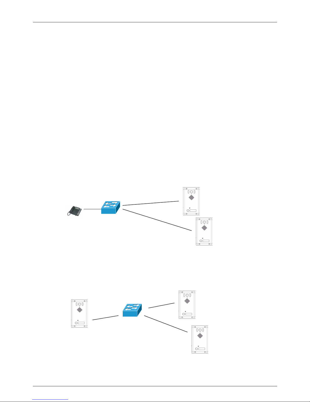
Example 1
In the installation there are 2 Doorphones, connected to the same network switch. From a telephone, I make a
voice announcement to the address 239.255.12.42:
Both Doorphones will reproduce the audio message announcement. It is possible to connecte more than the 2
devices as indicated in the example, since the only limit is the bandwidth of the network.
Example 2
In the installation there are 3 Doorphones. It is possible to use each system to play an announcement,
programming one of the four buttons to perform this function (for example the button 4):
Holding down the button 4 on Doorphone number 3, the audio captured by its microphone is sent simultaneously to
the Doorphones 1 and 2. Please note that it is possible to program each system so that it can send the audio
streaming to all the others and it is also possible to use all four keys only for the Multicast service.
AA-540 n. 1
Multicast address
239.255.12.42
AA-540 n. 2
Multicast address
239.255.12.42
AA-560 n. 3 with button 4
programmed for sending
audio Multicast to
address 239.255.12.42
LAN Switch
Multicast
predisposed
telephone
AA-540 n. 1
Multicast address
AA-540 n. 2
Multicast address
LAN Switch
Page 18
TEMA TELECOMUNICAZIONI SRL
Doorphone AA-560
MAS-AA560-REV04EN Page 18 of 65
7. COMMANDS AND CODES FOR THE INTERNAL OPERATOR
These are the main commands normally available when you are called by AA-560, the only ones that the operator
might need to know.
Upon receiving a call from AA-560, the communication will be activated and will be possible to send the commands
described here (default commands):
DTMF
Command
Function Description
#1
Activate the door opener
contact of the relay 1
Used to activate the electric lock connected to the first
relay during communication, it is a 2 digits code,
default #1.
#2
Activate the door opener
contact of the relay 2
Used to activate the electric lock connected to the
second relay during communication, it is a 2 digits
code, default #2.
#5 Extension of talking time
It is possible to reload the original time to continue the
call. AA-560 will play some alert tones 30 seconds
before closing the call.
*1 Set the Day mode
Set AA-560 in Day mode.
*2 Set the Night mode
Set AA-560 in Night mode.
*3 Set the Interval mode
Set AA-560 in Interval mode.
*0 Set the Automatic mode
AA-560 selects the operating mode in accordance with
a table of preset time slots.
Normally it is always possible to call AA-560 from any PBX extension to talk with a visitor who stands in the device
proximity, to send other DTMF commands, by simply dialing the internal extension number to which AA-560 is
connected.
Page 19
TEMA TELECOMUNICAZIONI SRL
Doorphone AA-560
MAS-AA560-REV04EN Page 19 of 65
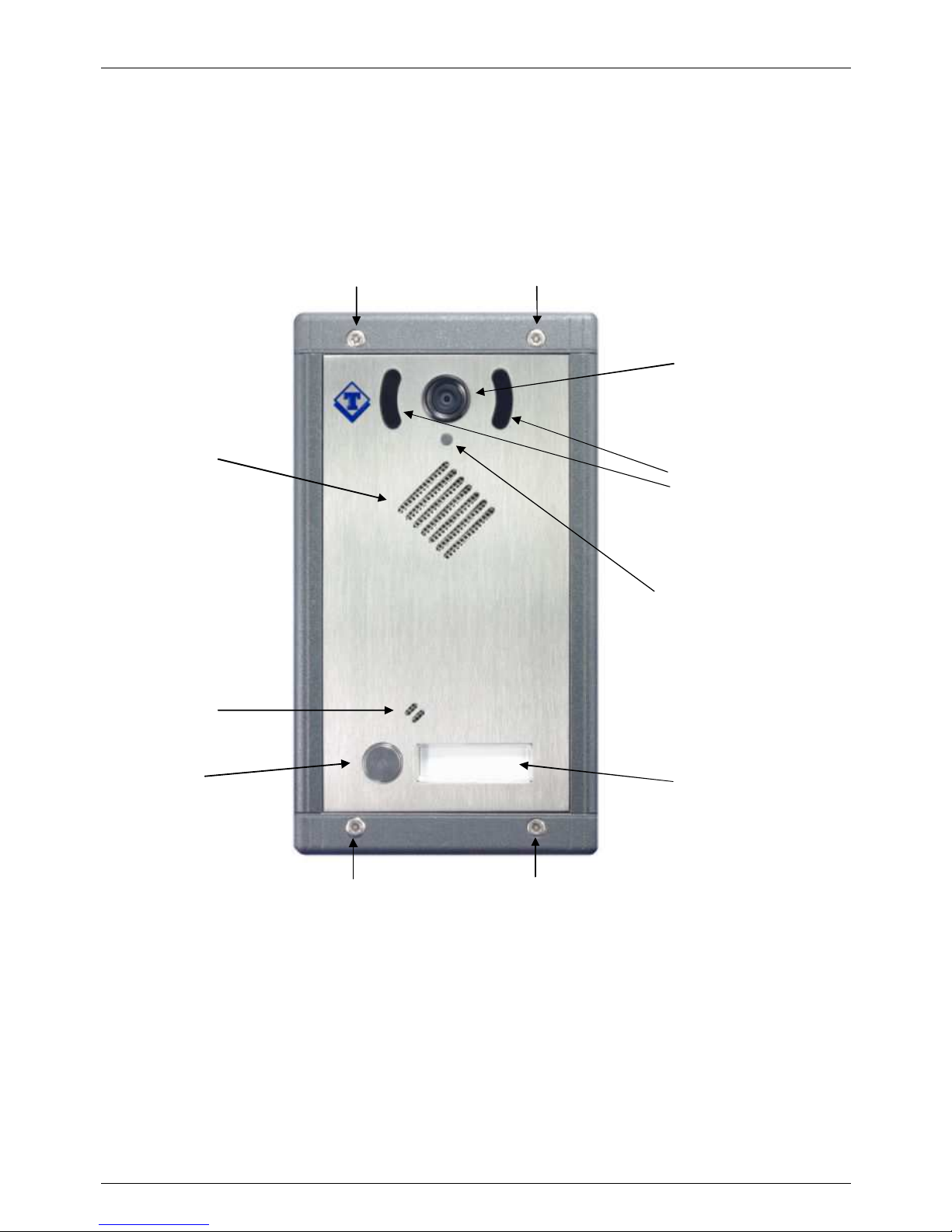
7.1. Signaling Led and AA-560 front panel description
Positioned above the speaker, AA-560 has a frontal signaling Led with two different modes of operation.
Whn the system is in stand-by, the Led is off. When the system is busy, the Led lights steadily and remains lit for
the duration of the conversation
Below are showed the parts on the system and their function.
Signaling Led
Label Holder
Speaker
Lighting Led **
Camera **
Call Button
Special closing screw
( note: ** = only in the models with camera )
Microphone
Special closing screw
Page 20
TEMA TELECOMUNICAZIONI SRL
Doorphone AA-560
MAS-AA560-REV04EN Page 20 of 65
8. INSTALLATION
8.1. Installation of systems
The units are presented with the exterior part elegant and compact, the only part that will be visible and with the
wall metal box to be recessed into the wall. It is possible to power AA-560 via the Ethernet connection if PoE
(Power Over Ethernet) is available. In this case it is possible to avoid the use of an external power supply but you
have to keep in mind that the power delivered from the PoE may not be sufficient for the proper functioning of the
internal relays and the simultaneous supply of external electric locks. To overcome this, just use a external power
source that will provide the current necessary for the proper operation of the electric connected to the relay
contacts. The front part with the electronics of the system is separable from the bottom metal wall box. This allows
a greater convenience during the preparation stages of the cables and the wall finish that will host the Doorphone.
The front panel with the circuit board (to preserve during the installation stages) could be separated from the metal
bottom and it can then be left out in an appropriate place and put into operation at the end of the preparation of the
wall and cables.
The following describes how to provide for the installation of the parts, while later in the manual will be described
how to connect the cables and more in the appendix there are the drawings, and the measures for the various
hardware elements.
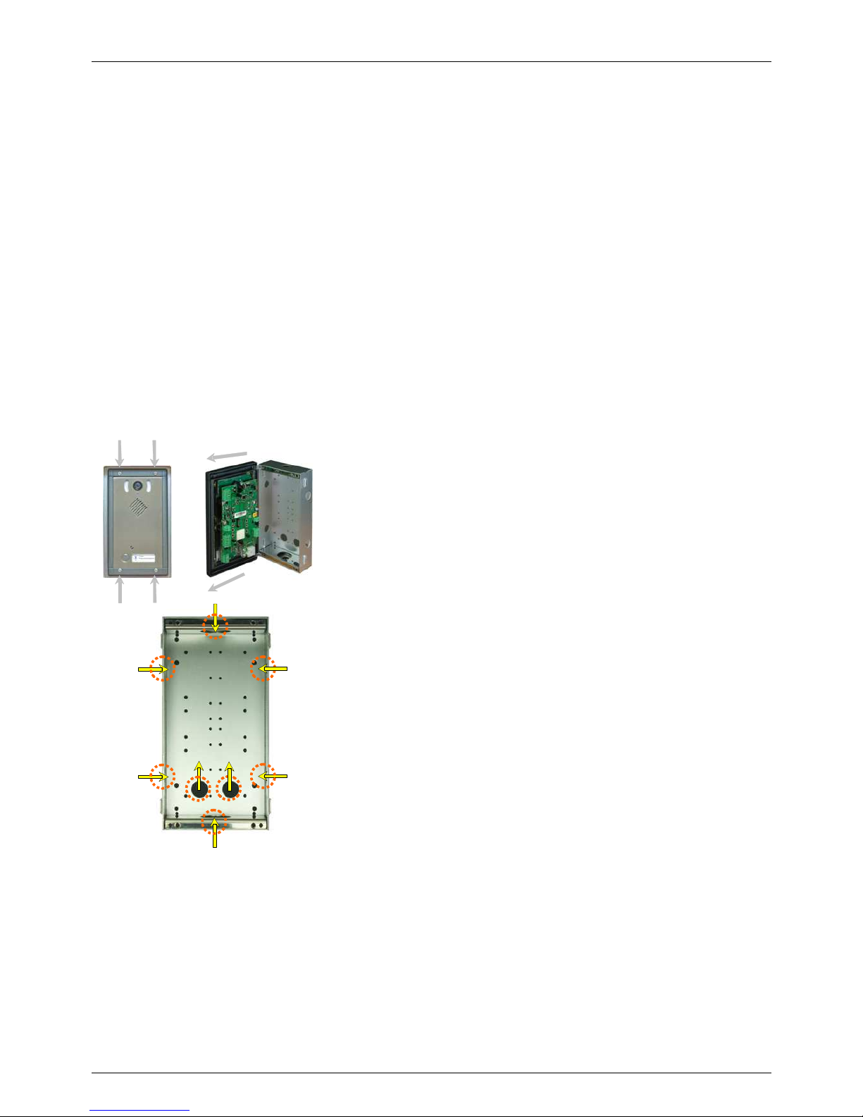
The four screws that secure the frame to the chassis are the first
accessible. Removing the four special screws on the front using the
special wrench provided in the kit, the frame will be free to rotate being
pivoted on the left side of the metal flushed container.
It is possible to pull out the metal frame hat holds the front and the
electronic card from the flush box in order to work only with the metal
box for placement operations and its flush mounting to walls. The metal
frame with the card is the only part of the system that will remain visible
flushed on the wall.
To help in "finishing" the wall, with particular reference to the edges
between the back box and the wall itself , there is the possibility to insert
between frame and box (then flush with the wall) a special accessory
called AA-549-C. This one improves the aesthetics of the system in the
case the wall is made of a material that can not be cut or not match to
the flush plastic box.
Moreover, this flat frame, applied between the wall and the aluminum
frame of the system once screwed, provides to help to seal the front/wall
junction. Keep in mind to prepare the wall with the arrival of the cables
coming out from their tubes run at the holes easily obtainable on the
plastic box (use the precut holes from where you want to route the
cables).
Do not use corrugated tubes or other with too small diameter to prevent to obstruct the passage of the
interconnecting of the system expansions (AA-539K). Consider it at least in the installation of the tubes between
the main system and the additional expansion modules. Once the metal base is placed and finished the masonry
and recessing work, it is possible to proceed to connect the signal cables to the system. The wires contained into
the walled metal box will connect then to the screw terminals on the card attached to the front of the system. For
details on connections, model by model, please refer to the following pages.
For the closing of the system after the cable connection, support the front aluminum frame aligning the two
transparent plastic plugs on their insertion holes on the left side of the flush metal box, gently push it until it stops,
turn then around the front to close the box and secure with the two special screws planned for this purpose. Ensure
that the panel rests firmly on the wall or on its AA-549-C aluminum frame (if present) and check that the cables are
properly seated and not get caught between the front panel and the rear box. At the end cover the screws with the
special plastic inserts supplied with making just slip into their seats.
Page 21
TEMA TELECOMUNICAZIONI SRL
Doorphone AA-560
MAS-AA560-REV04EN Page 21 of 65
Wall flat metal FRAME cover (Accessory option AA-549-C)
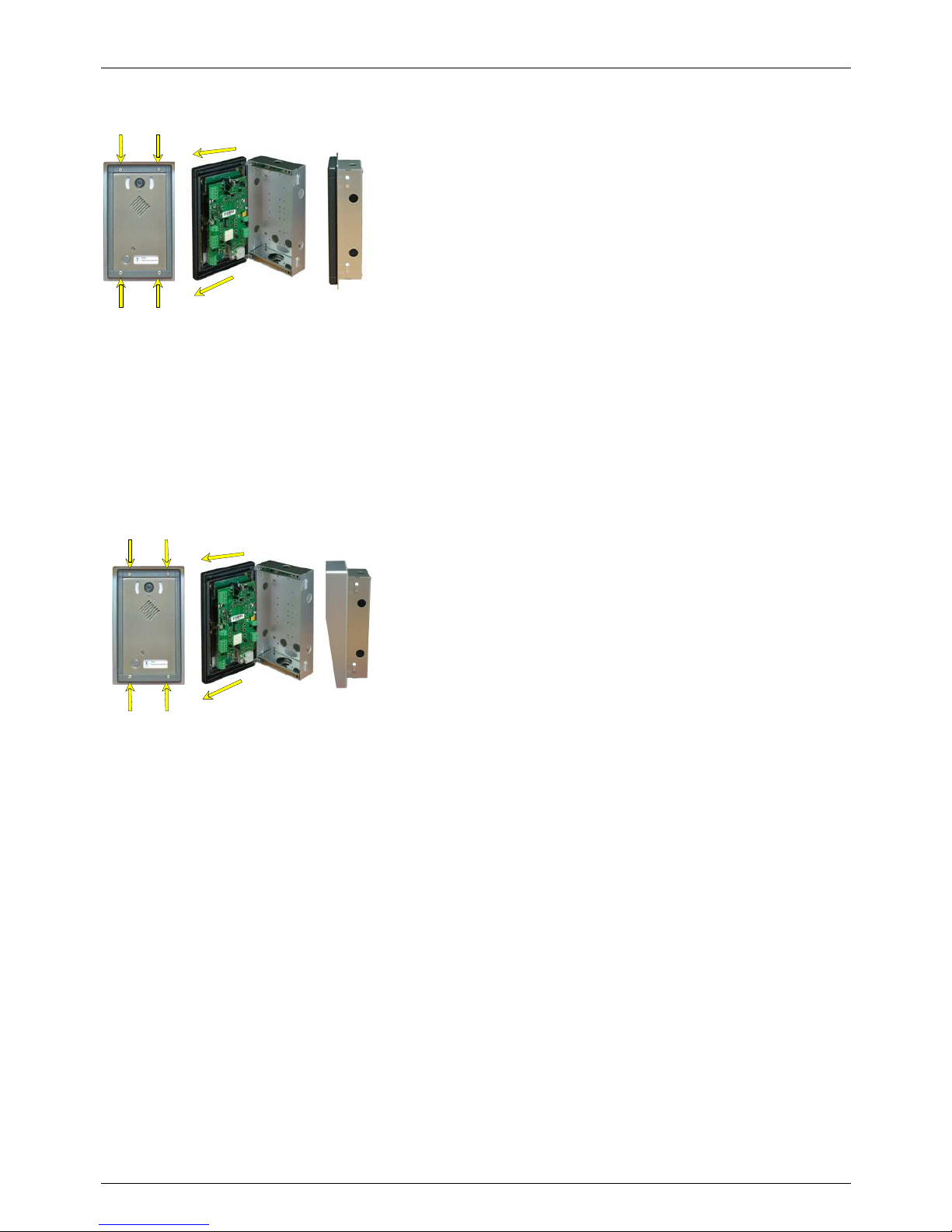
As already mentioned in the assembly operations of the system, there
exists the possibility of interposing between the front of the system and
the wall (where you will find the rear flush metal box) an optional flat
frame which has two main purposes of use.
The first purpose, aesthetic, allows it to be perfectly matched the outer
frame of the system masking the junction between the flush box a nd
the wall.
The second purpose, more technical, is to protect against external agents. In practice, by providing such frame in
the junction area of the flushed metal box and the front of the system, increases the resistance of the seal on the
perimeter of the external frame of the system regard to potentially infiltration.
The front panel has in fact a built-in gasket system that (if installed between AA-549-C and the system) seal any
gaps that may be left between the wall and the front of the system.
For installation of this accessory, see the steps on the previous page. The flushed metal box is the anchoring
element of the plain frame and of the front of the system when closed with the special front screws.
RAIN SHIELD cover (Accessory option AA-549-T)
This shield of non-invasive looking can be added to the system to
protect it from rain or water splashing from from an area close where
the system will be installed.
The metal box forming the back of the system remains to be recessed,
the shield (already inclusive of the flat frame AA-549-C described
above) interposes itself between the front of the system and the wall.
The shield will protrude from the wall only by protecting the front of the system.
For the operations involving installation of this accessory are still valid informations as described in the previous
page, just where the explanation applies to the flat frame, the same also applies to the shield.
The flushed metal box is the anchor element between the rain shield cover accessory and the front of the system
when closed with the special front screws.
Page 22
TEMA TELECOMUNICAZIONI SRL
Doorphone AA-560
MAS-AA560-REV04EN Page 22 of 65
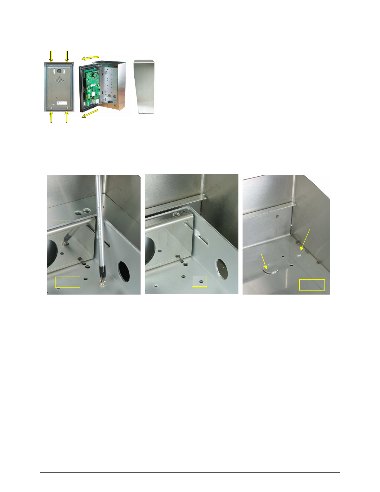
COMPLETE outdoor BOX (Accessory option AA-549-S)
The complete box is a cover that completely houses the AA-560
system, both the front panel which is protected as using the AA549-T shield, and also the metal rear box of the system.
Using the accessory AA-549-S it is no longer necessary to recess
the rear metal box of the system. The entire system will be housed
in the metal box AA-549-S and will be on the surface of the wall.
The complete box, unlike the other two previously described accessories, presents a radically different mode of
assembly. The tubes with electrical cables for the system should not be taken to be flushed metal box but directly
to one of the holes on the back (case with cables not visible) or face down box complete (case of exposed wires).
Take the box from its packaging and place it on a work surface.
•
Remove the front frame "CF", unscrew the 4 screws "A" on the bottom releasing the metal shell "GM" and
remove it.
•
Open the holes "B" you want to use for securing on the wall the full metal box "SC" with the help of a tool that
pushes away the preprinted material that covers every single hole to be released.
•
Open also the holes "C" that you want to use for the passage of cables, in the same way.
•
Place the full metal box "SC" directly on the wall to mark the holes to be made for fixing it. Perform drillings on
the wall for the provided anchors for fixing, finally place the metal box and tighten the screws of the anchors to
secure it to the wall.
•
Having previously defined the openings for cable entry on the metal box, open the corresponding pre-drilled
"C" also on the back metal shell "GM". It is possible to use one on the top or one on the bottom of the rear
(properly orienting the metallic shell "GM") and one on the lower side of the full metal box "SC".
•
Tighten the four screws "A" of the metal back "GM" to the metal box "SC" to reassemble it inside the metal
cover and re-seal the base of the front panel of the system.
•
Proceed to connect the cables to the system board (see connections section).
For the closing of the system after the cable connection and commissioning, support the front frame "CF", align the
two pins of transparent plastic of the front frame of the system on their insertion holes on the left side of the front
flat frame "CF ", insert gently until it stops.
Then rotate all over the front panel to close the box and get ready to tighten the 4 special screws planned for this
purpose. Ensure that the panel rests firmly on its aluminum frame, and accompany the cables verifying that are
properly seated and not get caught between the front and rear walls of the half-shell.
GM
CF
A
B
SC
C
Page 23
TEMA TELECOMUNICAZIONI SRL
Doorphone AA-560
MAS-AA560-REV04EN Page 23 of 65
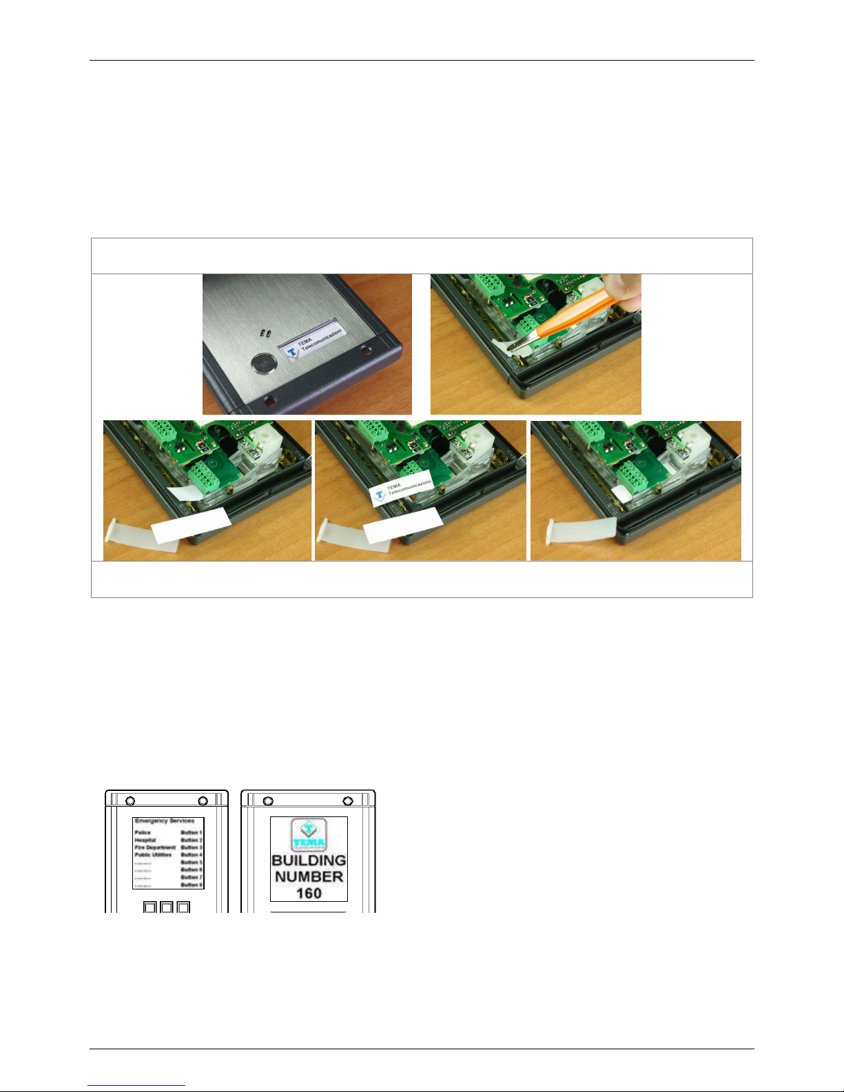
8.2. Inserting or replacing the names associated with the buttons and legend labels
Die-cut label holder
The front panel of the systems with the button has a nameplate field contained in the body of the button. It can be
accessed from the rear of the front panel and you have to act with a thin plier or a similar tool. You will find a precut white card badge on which you can write the description of the button or to use as a support for your card that
can be created and printed by yourself, keep in mind that this is made easier if you use the appropriate supplied
template file, customizable.
To access to the badges, with the system opened, pull with the help of pliers the sliding plastic tab found in his seat, pull it all
together with the labels.
Place now in reverse order first the custom label, the pre-cut card, and finally re-apply (always putting it sliding) the plastic
labels locking tab. Since the badges can be lit, avoid very thick or opaque or dark cards that will be hard to be visible.
Customizable cards for system legend areas
The front panel of the expansion includes a backlit transparent field useful to give informations for visitors. The
model AA-539R specially designed possesses even two areas. Because the informations to be presented can be
variables for text and graphical form, TEMA has provided a practical system of information badges customizing in a
text file can be edited directly by the person that install the systems or directly by the end user.
In the supplied CD-ROM is present an already prepared file with editable areas writable by the user with the correct
dimensions to be respected as a viewable area. No constraints, however, if not the imagination of those who create
the written information about the content and the style.
The creation of these information badges is simplified by the
use of images and precompiled examples in the above
described "template" document.
After the completion of the information to be presented, print
the necessary pages on a suitable paper, not too heavy to
not affect the ability of the backlighting. Then cut following
the indicated guidelines, in order to obtain the correct size of
information card from the prints.
Place the information cards in the seats provided during installation or subsequent customization at the end of work
as described in the following paragraphs.
Page 24
TEMA TELECOMUNICAZIONI SRL
Doorphone AA-560
MAS-AA560-REV04EN Page 24 of 65
8.3. CONNECTIONS
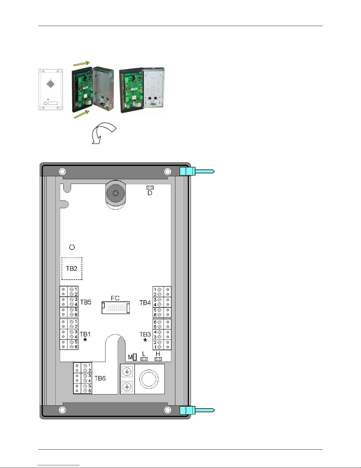
8.3.1. Connection of the base system AA-560
TB1, TB3
Respectively, the relay1 and relay2
circuits terminal block s.
* NOTE: the connections of these two
terminals are identical.
TB2
RJ45 socket for LAN connection. To
unplug the cable, press the tab on the
plastic connector block TB2 using the
hole and pull on the cable.
D
Jumper for default settings recovery
TB4
Terminals block 1-2 for connecting the
power source for the system AA-550 and
terminals block 3-4-5-6 for the Twilight
service keys backlighting when controlled
by the system relay 2 and redistribution
of the command to the eventually present
expansions
H
jumper for internal heating circuit
L
jumper for backlighting circuit
TB5
terminals block 1-2 for connecting
optional external speaker, terminals block
3-4-5-6 for the connection of input
contacts.
TB6
Terminals block for connecting
optoisolated input contacts
M
contacts to be shorted to improve the
performance of the microphone in a
particularly noisy environment
FC
polarized connector for connection of the
expansion cable to the AA-539K systems
For details of the connection of the signals on
terminal blocks TB1 and TB3 for the relays,
see section 8.4
Once that the bottom rear metallic box of th
e system is arranged in
the wall, take the front panel with the electronic board, insert the
two transparent plastic pins present on frame into the appropriate
holes on the wall box and get ready to connect the wires to the
terminal blocks. Make sure that all cables, including LAN, have not
yet been under tension before connecting them to the card. These
operations must be performed by a specialized technician. Take
the cables that have been prepared by one of the outgoing access
on the base system and start connecting. Remove, connect, and
replace the terminals according to the connections to be made. To
make the connections do not remove the system board from the
front panel but just remove the insertion connectors.
Page 25
TEMA TELECOMUNICAZIONI SRL
Doorphone AA-560
MAS-AA560-REV04EN Page 25 of 65
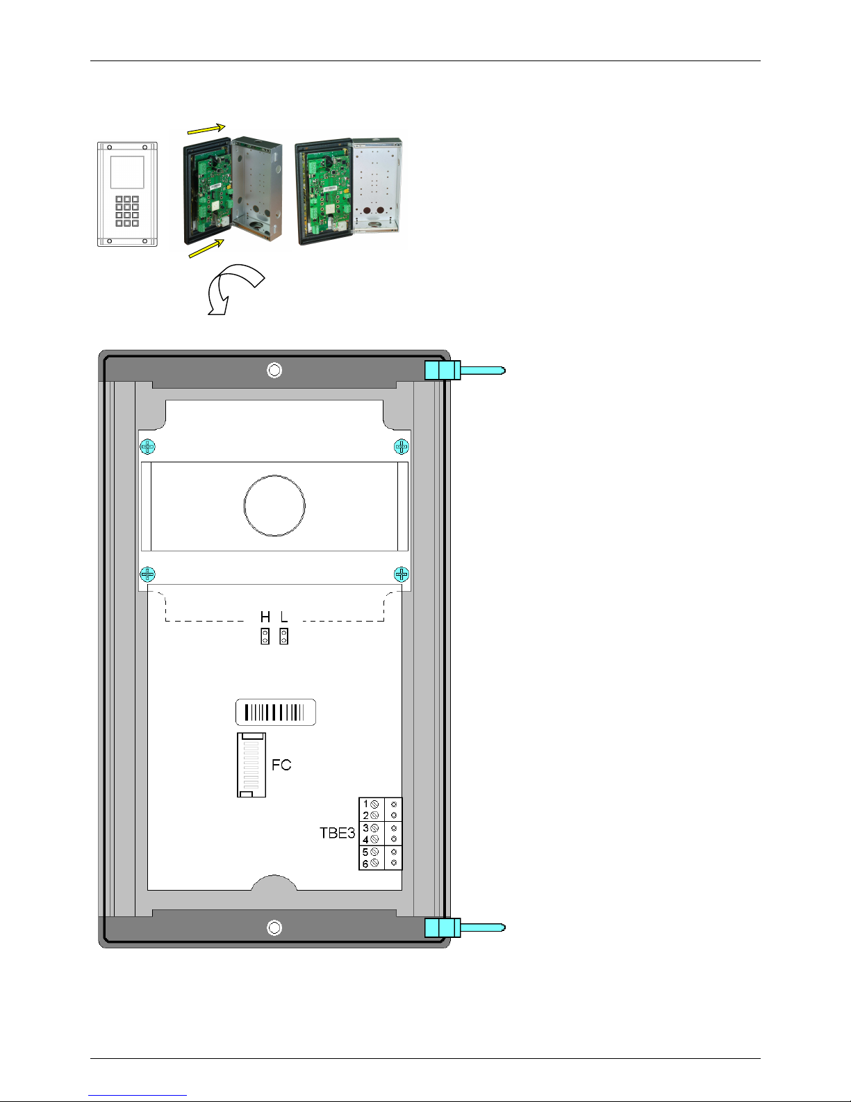
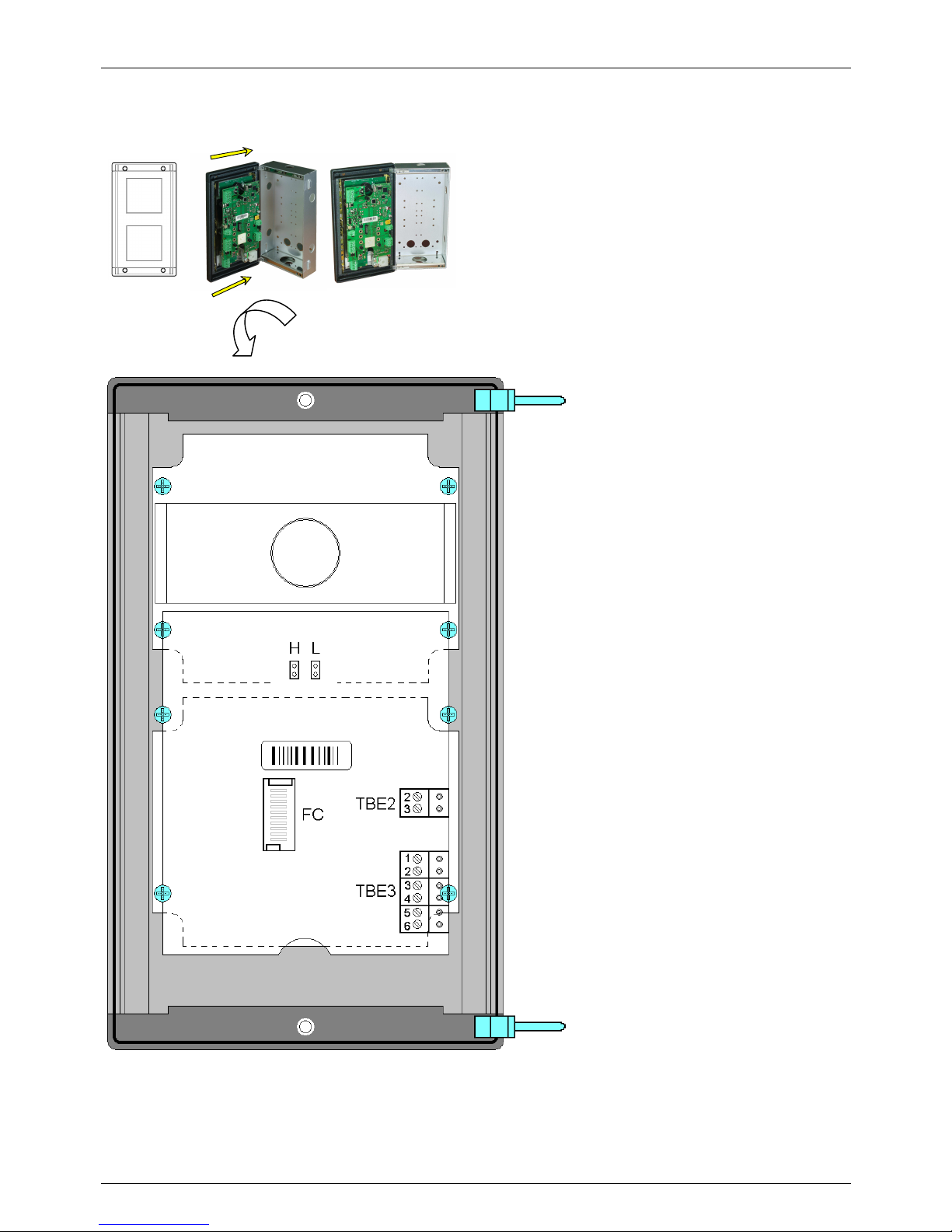
8.3.2. Connecting the system expansion AA-539K
Once that the bottom rear plastic box of the
system is arranged in the wall, take the front
panel with the electronic board, insert the
two transparent plastic pins present on frame
into the appropriate holes on the wall box
and get ready to connect the wires to the
terminal blocks. Make sure that all cables,
including LAN, have not yet been powered
before connecting them to the card. These
operations must be performed by a
specialized technician. Take the cables that
have been prepared by one of the outgoing
access on the base system and start
connecting. Remove, connect, and replace
the terminals according to the connections to
be made. To make the connections do not
remove the system board from the front
panel but just remove the insertion
connectors.
H
jumper for internal heating circuit
L
jumper for backlighting circuit
FC
polarized connector for connection of the
expansion coming from AA-560 system
TBE3
terminals block for the Twilight service keys
backlighting when controlled by the relay 2 of
the AA-560 base system and redistribution of
the command to the eventually AA-539R
expansions present in the plant
Inserting legend card
To extract/insert the front legend card just
"pull" the block of the upper card held
pressed by springs on the front of the system
on the points indicated in the drawing with
the circle and the cross head screw (not to
unscrew) and extract or insert the card
extract from the top possibly with the help of
tweezers.
After inserting the personalized card, verify
the correct positioning looking from the front
of the transparent block.
For details of the connection of the signals on
terminal block TBE3, see section 0
Page 26
TEMA TELECOMUNICAZIONI SRL
Doorphone AA-560
MAS-AA560-REV04EN Page 26 of 65
8.3.3. Connecting the system expansion AA-539R
Once that the bottom rear plastic box of the
system is arranged in the wall, take the front
panel with the electronic board, insert the two
transparent plastic pins present on frame into
the appropriate holes on the wall box and get
ready to connect the wires to the terminal
blocks. Make sure that all cables, including
LAN, have not yet been powered before
connecting them to the card. These
operations must be performed by a
specialized technician. Take the cables that
have been prepared by one of the outgoing
access on the base system and start
connecting. Remove, connect, and replace
the terminals according to the connections to
be made. To make the connections do not
remove the system board from the front
panel but just remove the insertion
connectors.
H
jumper for internal heating circuit
L
jumper for backlighting circuit
TBE2
terminals for connection of an additional
power source for the backlighting of this
expansion unit and any others following the
power supply capacity
TBE3
terminals block for the Twilight service keys
backlighting when controlled by the relay 2 of
the AA-560 base system and redistribution of
the command to the eventually AA-539R
expansions present in the plant
Inserting legend card
To extract/insert the front legend card just
"pull" the block of the upper card held
pressed by springs on the front of the system
on the points indicated in the drawing with
the circle and the cross head screw (not to
unscrew) and extract or insert the card
extract from the top possibly with the help of
tweezers.
After inserting the personalized card, verify
the correct positioning looking from the front
of the transparent block.
For details of the connection of the signals on
terminal block TBE2, see section 0
For details of the connection of the signals on
terminal block TBE3, see section 0
Page 27
TEMA TELECOMUNICAZIONI SRL
Doorphone AA-560
MAS-AA560-REV04EN Page 27 of 65
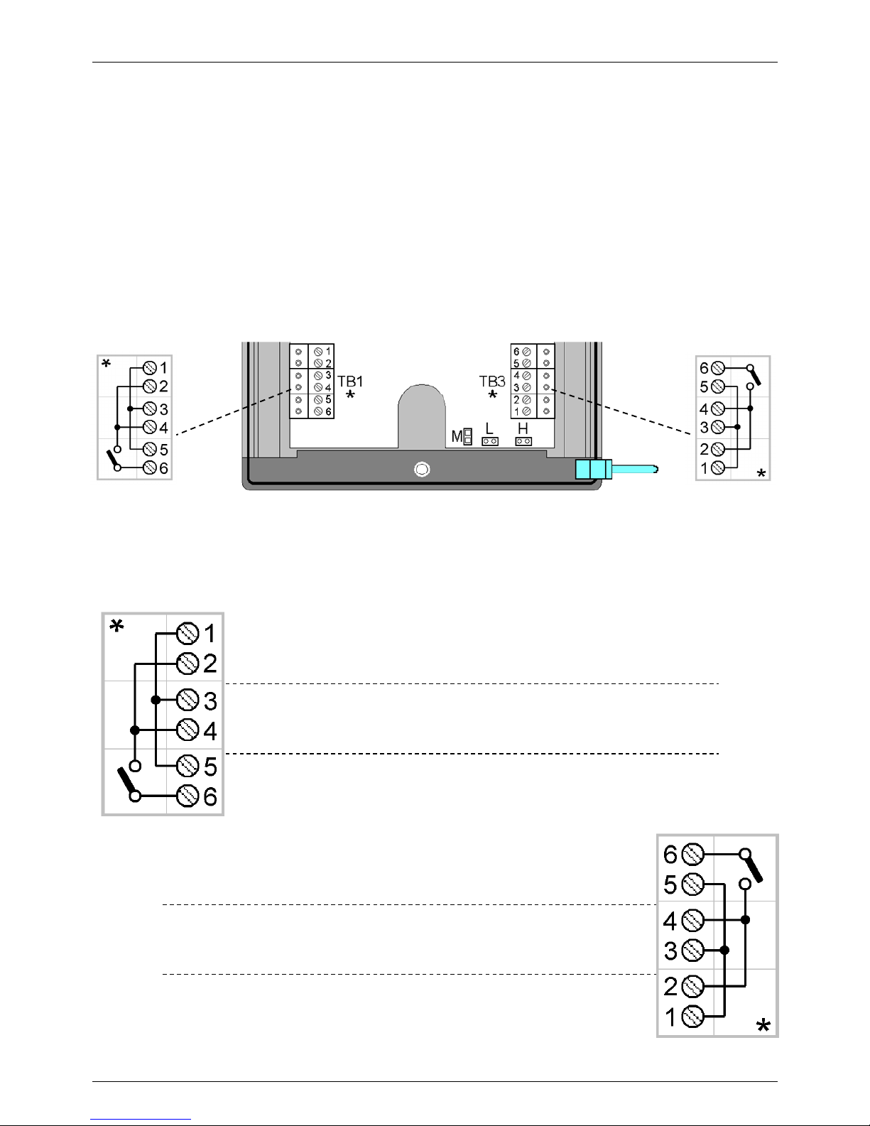
8.4. Description of the terminal blocks of relays
The circuits related to the relay 1 and relay 2 are equivalent but electrically separate and distinct. Each relay
provides one normally open contact "NO" that can be activated in closing. The operating mode of the two relays is
configured by setting some system parameters and is explained later in this manual.
The terminals are removable for convenience and ease of wiring. The two relays are both programmable and
usable to perform the opening of two different gates, while their additional functions in addition to the door opening
function, are different.
The blocks of terminal connections of the relays are arranged in the same way. This means that if there is the
need to swap the loads driven by the system after having made connections on TB1 and TB3, simply swap the
removable terminal block TB1 and TB3. Doing that, it is not required to reconnect in a different way as already
previously connected.
As described for the terminal block called TB1 (terminal block of relay1) therefore applies also to the block called
TB3 (terminal block of the relay2). Below is drawn the existing electrical connection on the AA-560 system board
for each block.
TB1 1
-2
Pair of terminals to redistribute the power source to other parts of the system
without having to connect two wires in the same terminal.
TB1 3-4 Pair of terminals to connect the power source for the load to activate with the
internal system relay.
TB1 5-6 Pair of terminals where is connected the load driven by the internal relay of
the AA-560 system. The maximum load capacity of the relay contact is 30V 2A.
TB3 5
-6
Pair of terminals where is con
nected the load driven by the internal relay of
the AA-560 system. The maximum load capacity of the relay contact is 30V 2A.
TB3 3-4 Pair of terminals to connect the power source for the load to activate with the
internal system relay.
TB3 1-2 Pair of terminals to redistribute the power source to other parts of the system
without having to connect two wires in the same terminal.
Page 28
TEMA TELECOMUNICAZIONI SRL
Doorphone AA-560
MAS-AA560-REV04EN Page 28 of 65
8.5. Description and examples of operation modes with the internal relays, connections
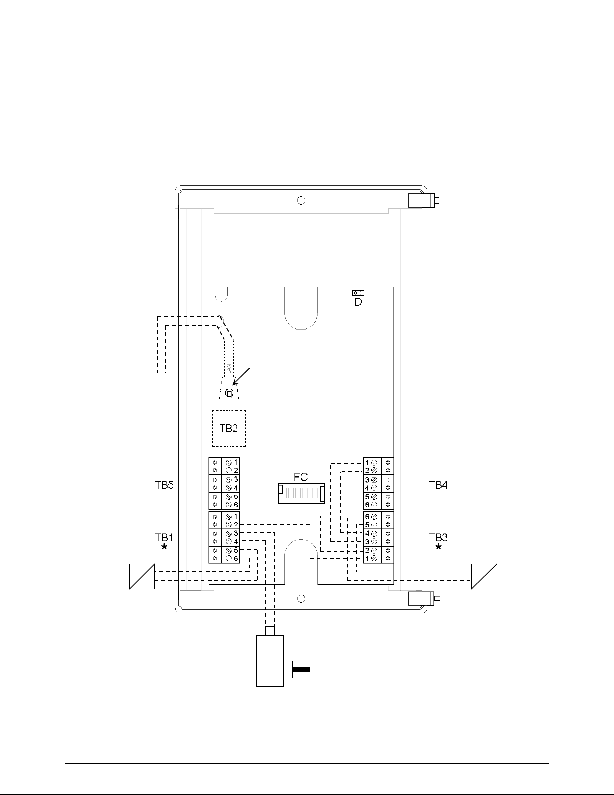
8.5.1. CASE 1 – drive of two electric locks with system powered
In this example AA-560 activates the two separate electric locks with a voltage pulse common to its own supply
voltage from an external power supply. In the example the relay1 acts on the electric lock of driveway gate, while
the relay2 acts the electric lock of the pedestrian gate. Please note that is needed to connect the terminal blocks
TB1, TB3, TB4 as shown, the power supply is unique and common. The LAN cable must be connected on TB2.
The connections to be made during the stages of installation are shown in dashed lines.
In this example the programming settings for the manageme nt of the relays could be:
the relay1 set as “Electric lock”, the relay2 set as “Electric lock”.
LAN network
cable
Power supply
12Vac
Pedestrian gate
electric lock
Driveway gate
electric lock
Hole for the release
of the connector
Page 29
TEMA TELECOMUNICAZIONI SRL
Doorphone AA-560
MAS-AA560-REV04EN Page 29 of 65
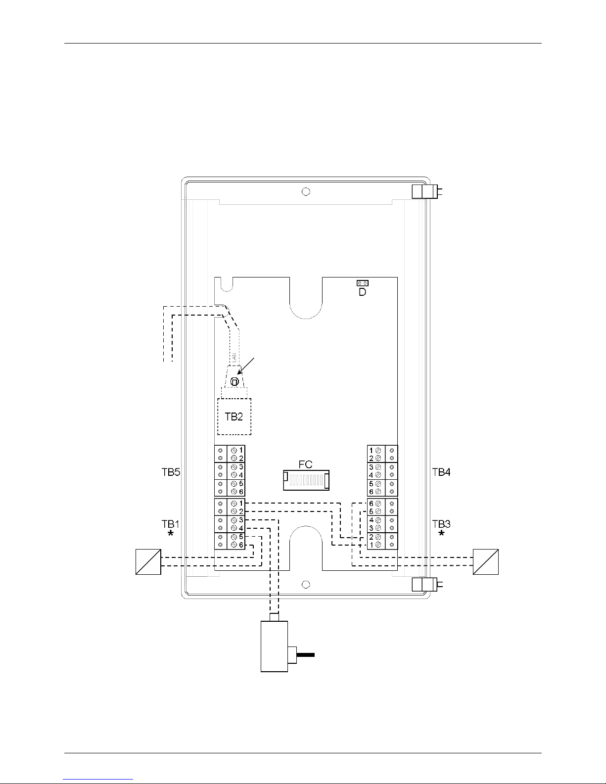
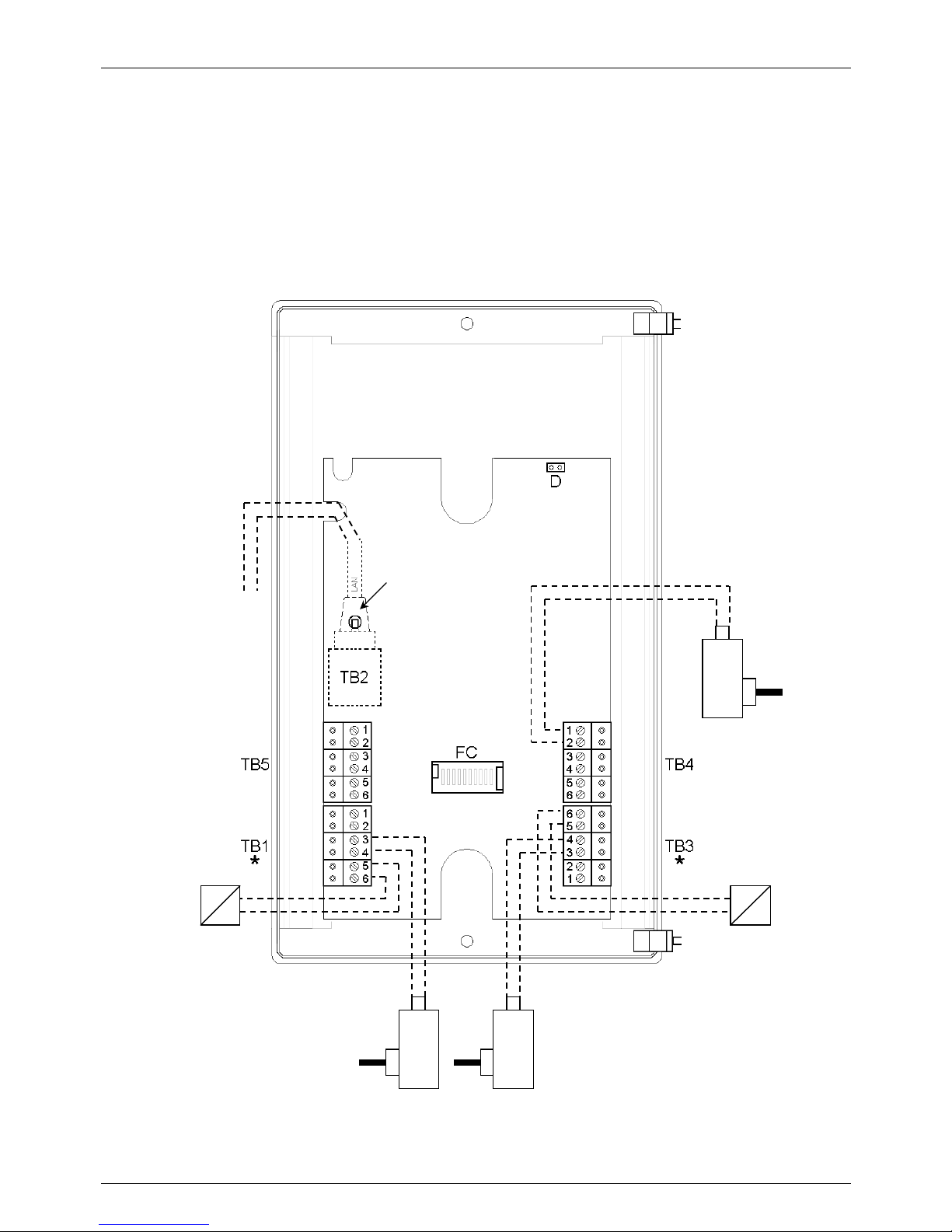
8.5.2. CASE 2 – drive of two electric locks, system PoE powered, one power supply
In this example AA-560 activates the two separate electric locks with a pulse of voltage common to the two electric
locks (from an external power supply). In the example the relay1 acts on the electric lock of driveway gate and
triggers the relay2 to follow for activate the electric lock of the pedestrian gate. Please note that is needed to
connect the blocks TB1 and TB3 as shown, the power supply is unique and common for the two locks and nothing
should be connected to terminal TB4 to power the system (AA-560 feeds itself from the LAN cable + PoE
connected to terminal TB2). The connections to be made during the stages of installation are shown in dashed
lines.
In this example the programming settings for the manageme nt of the relays could be:
the relay1 set as “Electric lock”, the relay2 set as “After relay 1” with a suitable delay to open the lock on the
pedestrian gate so that it will be opened more or less when the person who has entered from the main gate will
reach the second door.
LA
N network
cable
Power supply
12Vac
Pedestrian gate
electric lock
Driveway gate
electric lock
Hole for the release
of the connector
Page 30
TEMA TELECOMUNICAZIONI SRL
Doorphone AA-560
MAS-AA560-REV04EN Page 30 of 65
8.5.3. CASE 3 – drive of two electric locks with system powered with 3 different power supplies
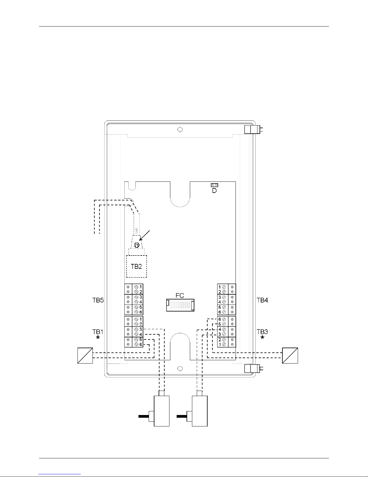
AA-560 activates the two separate electric locks and takes the power supply itself. Case with three different and
separate supply voltages. A first power source with a voltage of 12VAC is required for the system, a second power
source of 30V maximum for the first electric lock and a third power source of 30V maximum for the second electric
lock. Please note that not having been realized connections between different blocks (the system itself and the two
electric locks) the three power supplies provided to the system remain independent between them. Note the distinct
connections on the blocks TB1, TB3 and TB4. The LAN cable must be connected on TB2. The connections to be
made during the stages of installation are shown in dashed lines.Using the possibilities of connection of the power
supplies and loads offered by AA-560 it is possible to get a great flexibility of use in driving loads with different
electrical characteristics between them.
In this example the programming settings for the manageme nt of the relays could be:
the relay1 set as “Electric lock”, the relay2 set as “Electric lock”.
LAN network
cable
Pedestrian gate
electric lock
Driveway gate
electric lock
Hole for the release
of the connector
Two separate
power supplies for
the two electric
locks (Max 30Vac)
Power supply
12Vac for the
system
Page 31
TEMA TELECOMUNICAZIONI SRL
Doorphone AA-560
MAS-AA560-REV04EN Page 31 of 65
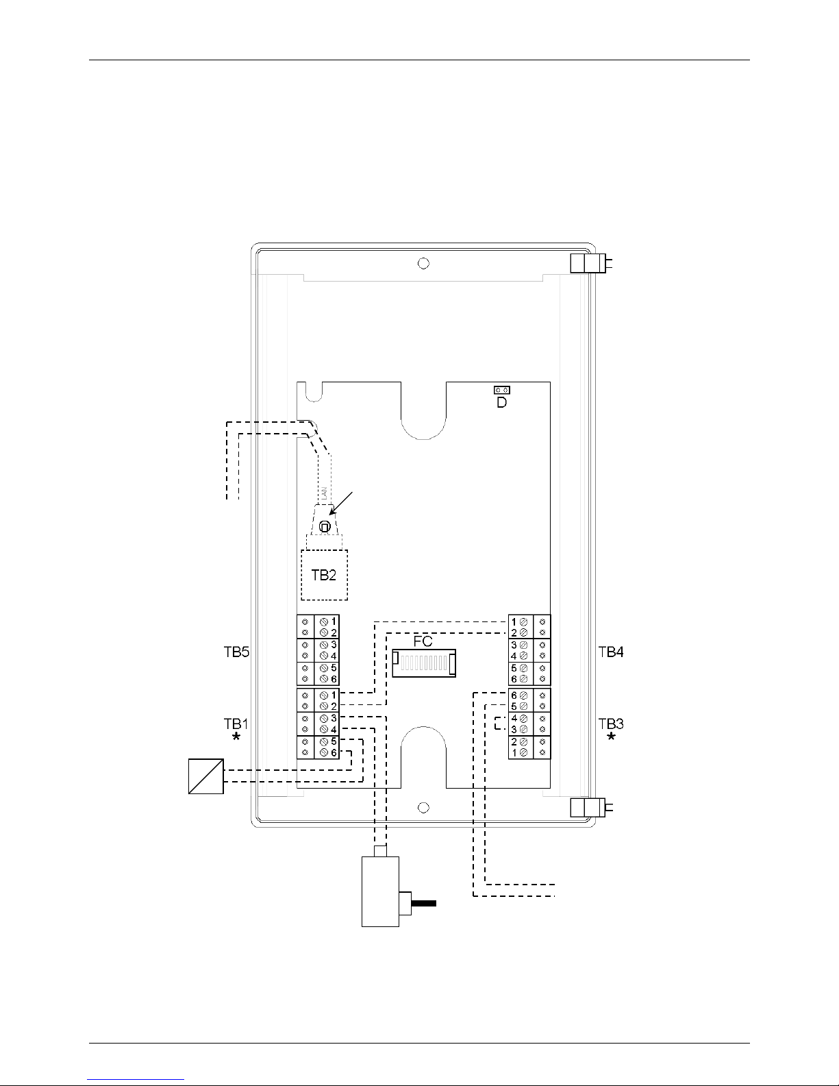
8.5.4. CASE 4 – drive of two electric locks, system PoE powered, two separate power supplies
AA-560 activates the two separate electric locks and takes the power supply itself. Case with three different and
separate supply voltages. In this example, however, the power source of the system is the LAN + PoE connection.
There are also a second power source of 30V maximum for the first electric lock and a third power source of 30V
maximum for the second electric lock. Please note that not having been realized connections between different
blocks (the system itself and the two electric locks) the three power supplies provided to the system remain
independent between them. Note the distinct connections on the blocks TB1, TB3 and TB4. The LAN cable with
PoE power supply option must be connected on TB2. The connections to be made during the stages of installation
are shown in dashed lines. Using the possibilities of connection of the power supplies and loads offered by AA-560
it is possible to get a great flexibility of use in driving loads with different electrical characteristics between them.
In this example the programming settings for the manageme nt of the relays could be:
the relay1 set as “Electric lock”, the relay2 set as “Electric lock”.
LAN network
cable
Pedestrian gate
electric lock
Driveway gate
electric lock
Hole for the release
of the connector
Two separate
power supplies for
the two electric
locks (Max 30Vac)
Page 32
TEMA TELECOMUNICAZIONI SRL
Doorphone AA-560
MAS-AA560-REV04EN Page 32 of 65
8.5.5. CASE 5 – drive of an electric lock and an opening buzzer
Case expected to automatically repeat the activation of the relay1 (typically door opener) also on relay2 so it is
possible to connect to the second relay a device to signal the successful opening of the gate. For example, to a
warehouse where workers assume responsibility to pay attention to an adequate buzzer that indicates the effective
opening of the passage. The device drived by the AA-560 relay2 provide to notify (for the time of activation of the
relay1) that a person is entered in the warehouse. Automatically, every time a gate is opened, is carried out an alert
for the warehouse employees. TB3 is designed for use only contact relay2, the system is powered on TB4, on TB1
connects the electric lock and on TB2 the telephone line.
In this example the programming settings for the manageme nt of the relays could be:
the relay1 set as “Electric lock”, the relay2 set as “After relay 1” with a very short delay to immediately notify the
activation of relay1 door opener and with a duration (activation time of the relay 2) useful for the duration of the
desired buzzer sound.
Contact of relay 2 of
AA-550 to connect
to the signaling
system, connect
together the points 3
and 4
LAN network
cable
Power supply
12Vac
Driveway gate
electric lock
Hole for the release
of the connector
Page 33
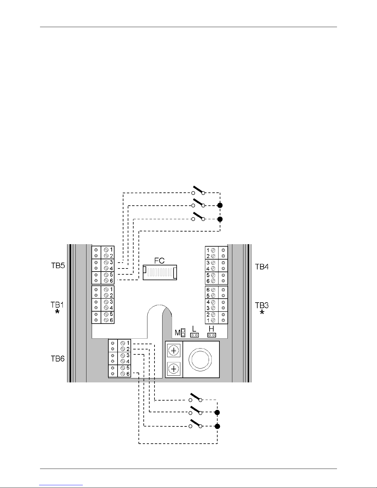
TEMA TELECOMUNICAZIONI SRL
Doorphone AA-560
MAS-AA560-REV04EN Page 33 of 65
8.5.6. Input connections
AA-560 has six inputs for acquisition of external contacts (3 of each: 4, 5, and 6 optoisolated) useful to indicate
special conditions or alarm. Upo n detection of activation of the contact connected to each input, it can be
associated with a different phone number to contact (to which the operator that must handle the event must
answer).
Usually the inputs of the system are connected to normally open contacts that its closing will active the call
sequence signaling. It’s possible to program the system to reverse this way of detection, so that the acquisition of
activation of the contact and the triggering of the respective signaling takes place after the opening of a contact that
is closed under normal conditions.
AA-560 continuously monitors the status of its three inputs (and the respective external contacts connected).
In case of activation conditions, AA-560 stores it in non-volatile memory and is responsible for triggering the cycle
of notifications. In case of AA-560 power off, when the power come back the system alerts will be resumed.
The connector TB5 contacts also has the terminals for connecting an additional external speaker.
Connection of external contacts to the terminal strip TB5 and TB6
T
B5.3 Input 1
TB5.4 Input 2
TB5.5 Input 3
TB5.6 Common
On terminal
block TB5
Terminal block
TB6
TB6.1 Input 4
TB6.2 Input 5
TB6.3 Input 6
TB6.4 – (not used)
TB6.5 Common
TB6.5 Common
Page 34
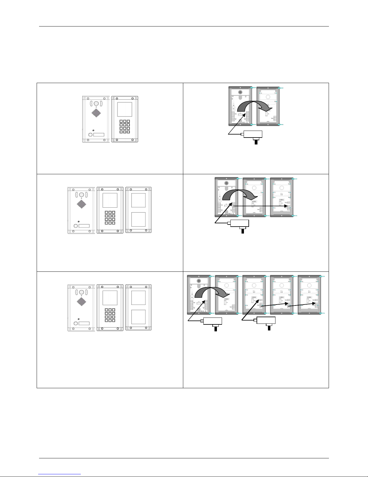
TEMA TELECOMUNICAZIONI SRL
Doorphone AA-560
MAS-AA560-REV04EN Page 34 of 65
8.5.7. Connection between base unit and expansions
Here are some examples of compositions obtainable by the various modules of the AA-560 system. In addition to
the required connections to the AA-560 base system between a module and another one (as detailed in the
descriptions and examples on previous pages), for the backlight of the AA-556R expansion legend module are
required other connections as indicated in the following table.
Pair AA-560 + AA-539K
Connect the two modules using the FC flat cable
supplied with the expansion module, power only the
base system with AL-39AL on TB4.
AA-560 + AA-539K + AA-539R
The cascade connections from the AA-539K module to
the next AA-539R modules can not be performed in the
event that it is not necessary to backlight or not heat the
area of the legend of the modules.
Connect the base system to the keyboard expansion
using the flat cable supplied with the expansion module.
Then connect the TB4 terminal block of the AA-560
base with the TBE3 block terminal of the first
expansion, and so on.
AA-560 + AA-539K + three AA-539R modules
Keep in mind the power consumption of all modules
that are going to be connected with the various enabled
functions (for example, backlight and anti condensation
when necessary).
Connect as in the previous example. Pleae note the
presence of two power supplies needed in this example
to divide the loads based on the power consumption of
backlight and anti condensation circuits of all modules.
1.5A
1.5A
1.5A
1.5A
Page 35
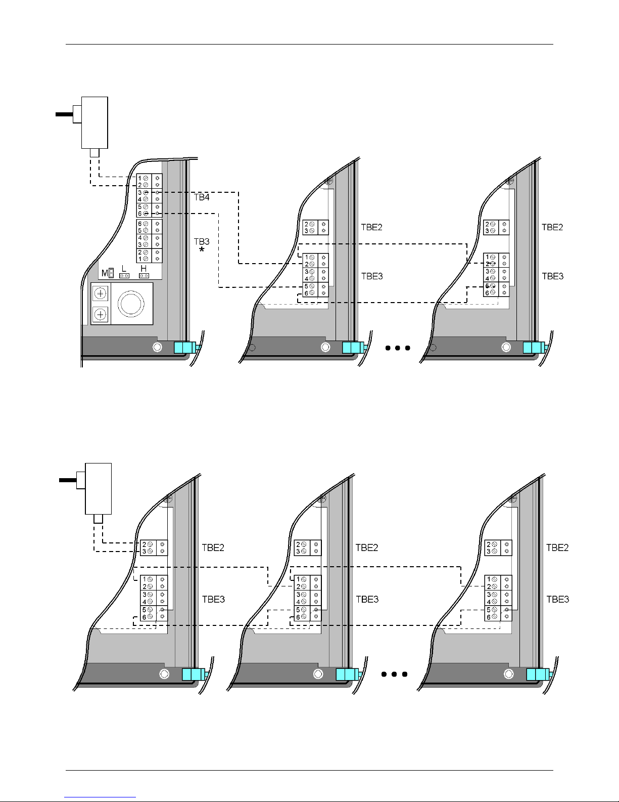
TEMA TELECOMUNICAZIONI SRL
Doorphone AA-560
MAS-AA560-REV04EN Page 35 of 65
AA-560 AA-539R AA-539R
Power supply
12Vac
AA-539R AA-539R AA-539R
Power supply
12Vac
8.5.8. Connecting AA-539R modules in cascade starting from a AA-560 base module
8.5.9. Connecting AA-539R modules in cascade starting from a AA-539R powered module
Page 36
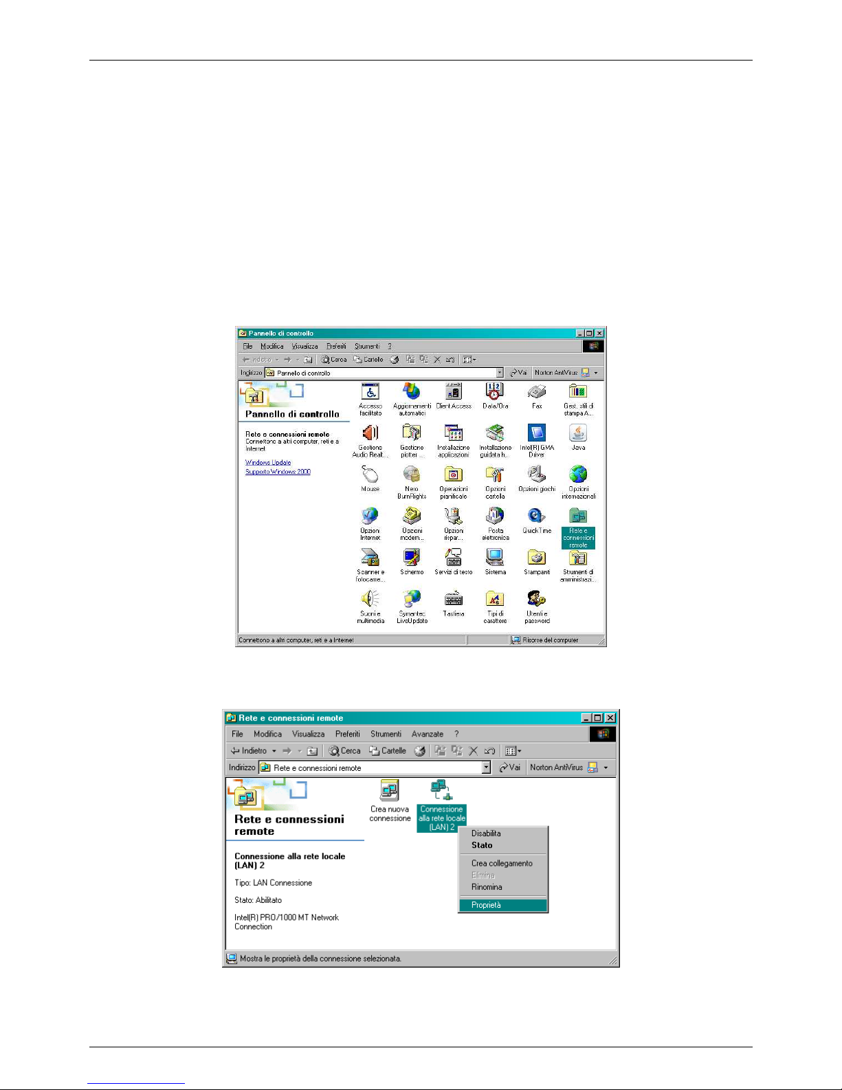
TEMA TELECOMUNICAZIONI SRL
Doorphone AA-560
MAS-AA560-REV04EN Page 36 of 65
9. PROGRAMMING
9.1. Preparing for programming system parameters
Programming is done via web interface. To access, simply connect an Ethernet cable from a PC or a hub to the
LAN port of AA-560.
The default IP address of AA-560 is “192.168.0.10”.
Remember that in order to successfully connect to the web interface of AA-560, it is necessary that, in the IP
addresses configuration of your PC, is present the subnet 192.168.0.x, where "x" is any number between 1 and
254 and different from 10. See below how to configure your PC to reach the correct subnet. The procedure shown
applies to Windows® 2000, but is similar to later operating systems, such as Windows® XP.
Open the Windows Control Panel and select Network Connections, as shown below:
You must now find your connection to the LAN, choosing the one referring to the network adapter you are using to
connect with AA-560. See the following figure:
Page 37
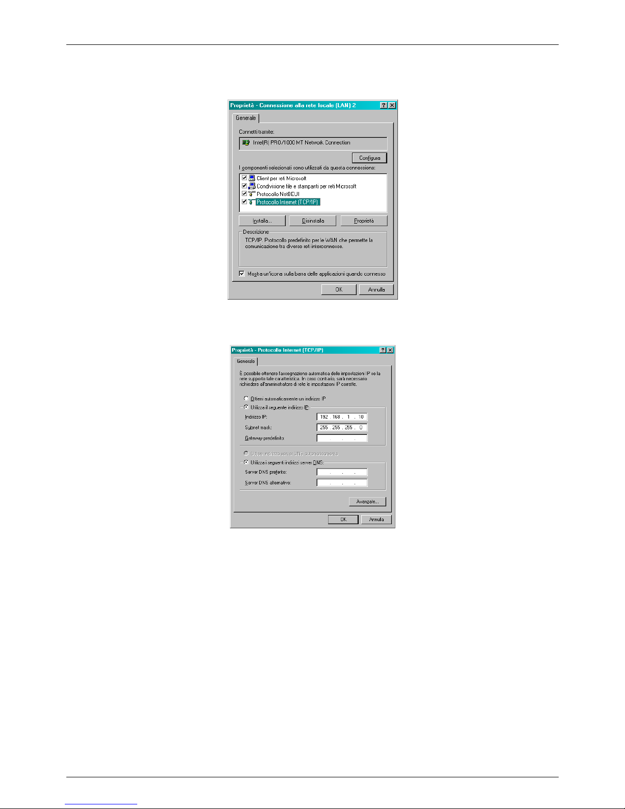
TEMA TELECOMUNICAZIONI SRL
Doorphone AA-560
MAS-AA560-REV04EN Page 37 of 65
Once you find the right connection, click on it with the right mouse button and from the pull-down menu that
appears choose "Properties". Then the following window appears:
From the previous window, click "Internet Protocol (TCP / IP)" and click on "Properties". This will open the following
window where it is possible to configure the IP addresses that the network card will use:
If the PC is already on subnet 192.168.0.x with a mask 255.255.255.0, ignore the following steps. Otherwise,
proceed as follows. (The address of the PC configuration should not be 192.168.0.10).
Remember the current TCP / IP configuration of your computer for any subsequent restore of the correct
parameters.
Click "Use the following IP address" and type in the appropriate field the following IP address: 192.168.0.11
(instead of "11" used in the example it is possible to enter any number between 1 and 254, but excluding the 10
which is the default address of the door phone to be programmed). In the "Subnet Mask" enter the netmask
255.255.255.0. Click OK to confirm the changes. The PC is now ready to configure the door phone. Remember at
the end of programming to restore the network configuration of the PC to its original state if necessary.
Once you have successfully configured the IP address of your PC, it is possible to reach the Web interface to
configure AA-560.
Page 38
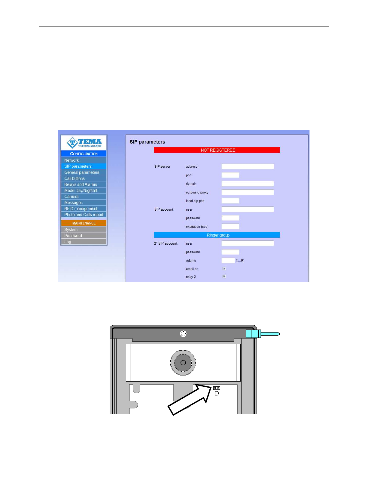
TEMA TELECOMUNICAZIONI SRL
Doorphone AA-560
MAS-AA560-REV04EN Page 38 of 65
9.2. Access to programming and reset address and password
To program the device, it is sufficient to use a standard browser such as Explorer, Firefox, Chrome or other. The
default address of the device is 192.168.0.10 with a mask of 255.255.255.0, and the user / password with which to
connect are master / master. Make sure you have access to this network segment from your computer
Once logged in, it is possbile to change the administrative password for the maximum safety of your device, see
par. 10.2.
The use is very simple and intuitive, it is always visible on the left the menu for selecting the functions to be
programmed, while on the right is shown the configuration window that is currently active. Any change will be
confirmed by pressing the "Apply" or "Save" buttons. Closing the browser or changing the page without selecting
those buttons will make lost any change.
Any changes does not require a restart of the device (except for the IP address change and update the software).
In case it is necessary to program a device for which are not known network address or password, it is possible
restore the default by closing the appropriate jumper inside the device:
Just keep the bridge closed for at least 5 seconds. In this phase the LED inside the card turns on and s tarts
flashing after this time. After the flashing is possible to reopen the jumper and reboot the device (the restoration
was carried out properly). No configuration parameter is lost, except the network address and the password.
To restore the device to factory state, proceed with the software reset (see par. 10.1).
Page 39
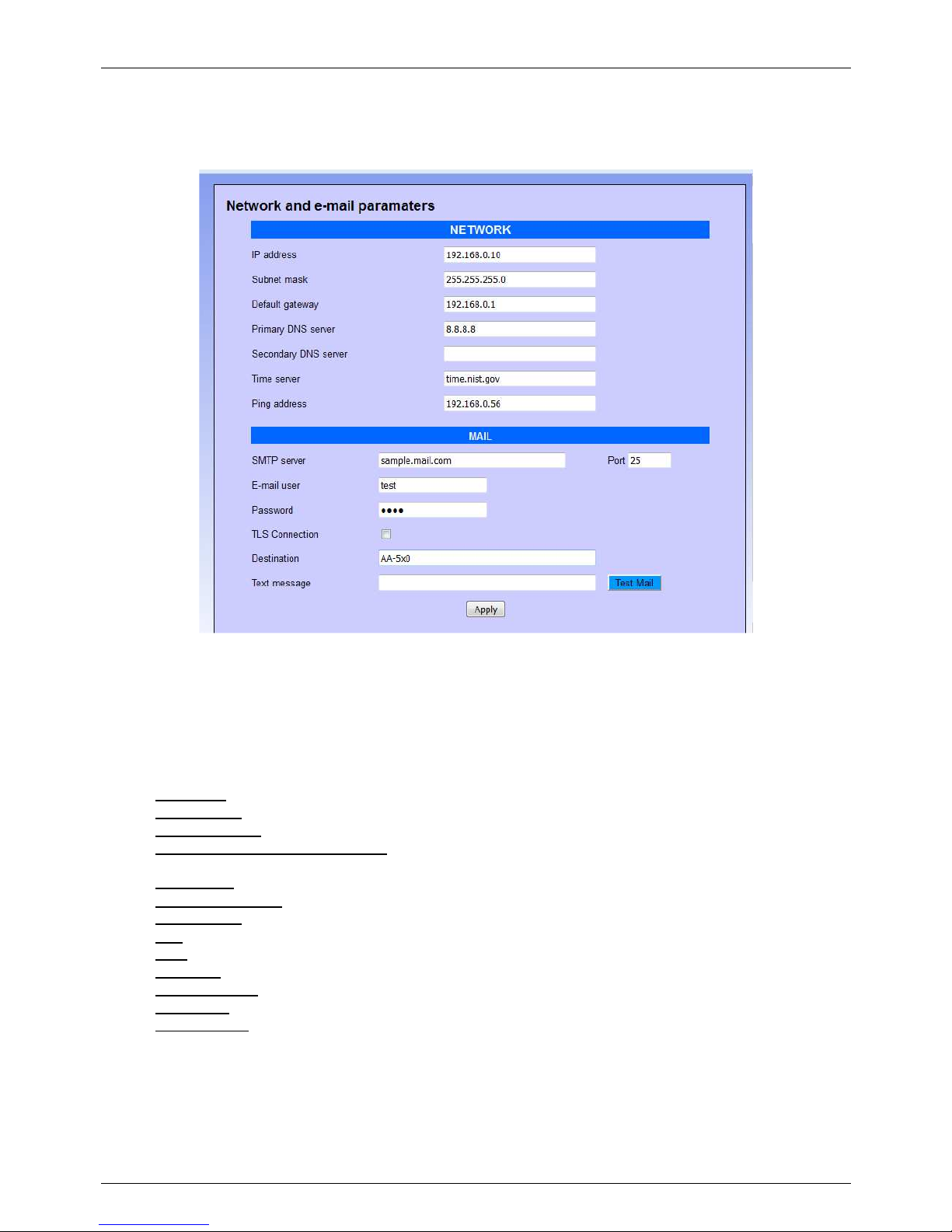
TEMA TELECOMUNICAZIONI SRL
Doorphone AA-560
MAS-AA560-REV04EN Page 39 of 65
9.3. Network parameters
On this page it is possible to set the network parameters, such as IP address, netmask, etc.:
The default IP address of the device is 192.168.0.10/24. Gateway and DNS are only needed if you want the device
to have the ability to access the Internet (for example to get the current date / time, in the example from the site
time.nist.gov).
The changes to the network settings are taken over by the device until the next reboot. Once you have completed
the configuration steps so be sure to reboot the system and if necessary, change the network segment of your
computer so that it can connect to the new address.
• IP address: specify the IP address you want to assign to AA-560.
• Subnet mask: indicate the subnet mask to be assigned to AA-560.
• Default gateway: indicate the gateway that can enable AA-560 to access to internet.
• Primary and secondary DNS server: indicate the addresses of two DNS servers you want to use to resolve
IP addresses.
• Time server: indicate the address of the server you want to use for time synchronization device.
• Test address (ping): if programmed, this field contains the address used to test the network card.
• SMTP server: name or IP address of the mail server.
• Port: tcp port for the connection. Usually is 25
• User: authenticated user on the SMTP server
• Password: SMTP authentication password
• TLS connection: activate the secure connection
• Destination: email destination
• Text message: text to be included in the email sent
The button “Test Mail” can be used to test immediatly if the configuration works.
Page 40
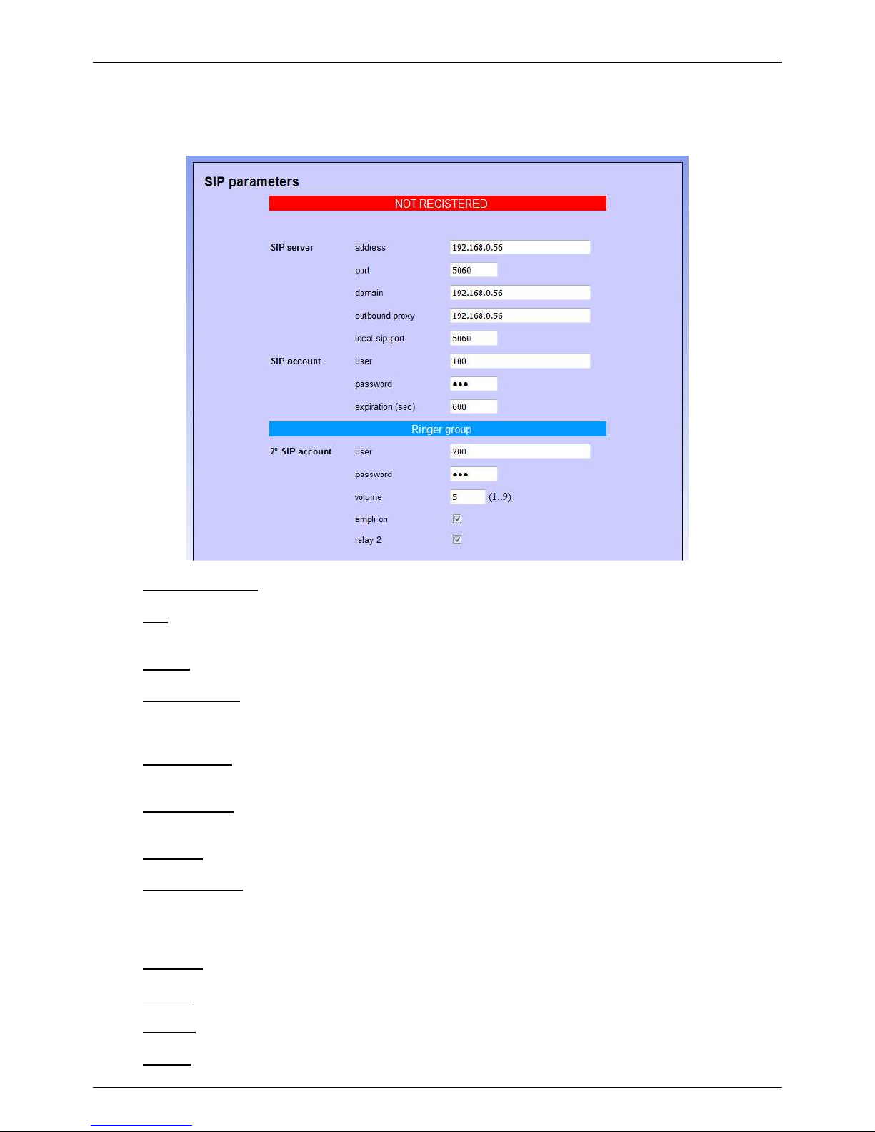
TEMA TELECOMUNICAZIONI SRL
Doorphone AA-560
MAS-AA560-REV04EN Page 40 of 65
9.4. SIP parameters
Once the network parameters have been set correctly, you must configure the connection with the SIP-VoIP PBX:
• SIP server address: specify the IP address of the SIP PBX to which AA-560 should connect.
• Port: is the port number of the SIP PBX AA-560 which has to forward incoming calls. Generally it is the
5060, but some stations use a different port.
• Domain: domain where register the client.
• Outbound proxy: some PBXs require that the extension number to call is followed by the proxy address. In
most cases this field can be left empty.
• Local SIP port: generally the 5060 port is used, but it is possible to specify a different number (i.e. for
particular routing tables)
• User/password: credentials for the registration of the extension (which obviously must have been already
created on the PBX).
• Expiration: indicates how many seconds the device should check the correct registration of the client.
• 2
ND
SIP account: this account is used for “Night ringer”. It is possible to configure, in the PBX, a ringer
group used in night mode, so if the doorphone is put in the same group, it will play the ringer message
(see par. Errore. L'origine riferimento non è stata trovata.) when receiving an incoming call, without
answering.
• Password: the second account password.
• Volume
: volume of the ringer. It is also the volume used to reproduce the prerecorded announcements.
• Ampli on: no function in this model
• Relay 2: when the call is going on, it’s possible to activate the relay 2. It could be useful for example to
connect a light, a flash, etc.
Page 41
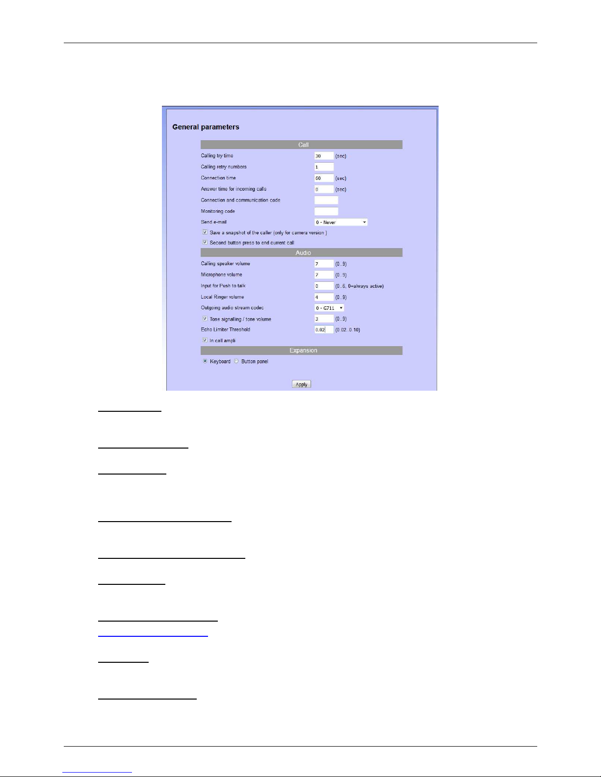
TEMA TELECOMUNICAZIONI SRL
Doorphone AA-560
MAS-AA560-REV04EN Page 41 of 65
9.5. General parameters
In this section it is possible to set parameters for general use, such as call duration, audio volume, tones, ringing
and so on:
• Calling try time: determines how long should be, in seconds, the call attempt to the extension (the called
number is ringing but not responding). At the end of the attempt, the software may be called the second
programmed number.
• Calling retry numbers: number of times that must be made the call cycle. At the end of the count of this
parameter is called a possible supervisor
• Connection time: once in connection with the extension, the call is torn down anyway after the set time.
Thirty seconds before the end of the call, the system will emit a short beep to the user within the company
and repeats the message every 5 seconds. At this stage it is possible to type on the extension phone the
sequence "#5", which forces the connection time to be reloaded.
• Answer time for incoming calls: when the system is called, it answers after the set time. If set to 0,
responds immediately, if 999 never answers. In any case, when there is an incoming call, it is possible to
answer by pressing any key.
• Connection ad communication code: when the device receives an incoming call, if this field is programmed,
the audio will not be connected until the user will enter the right connection code.
• Monitoring code: as in the previous case, for incoming calls, the audio is not connected until the code is
entered, but in this case only the audio from microphone is connected (a sort of “monitor” function, it is
possible to hear the audio near the doorphone without being heard).
• Save a snapshot of the caller: (valid only for Tema Doorphones with camera).
• Second keypress to close: it is possible to choose whether, during a call made by the visitor, a further
pressure of a key should interrupt the pressure or if it should be ignored.
• Send e-mail: it is possible to choose whether to send an email (to the address given in the configuration
page of the network). Any mail sent as an attachment will have the image of someone who has pressed the
call button.
• Calling speaker volume: sets the volume of the audio to the external user. Possible values range from 0
(very low) to 9 (very strong).
Page 42

TEMA TELECOMUNICAZIONI SRL
Doorphone AA-560
MAS-AA560-REV04EN Page 42 of 65
• Microphone volume: Sets the microphone sensitivity and consequently the volume of the audio to the user
within the company. Possible values range from 0 (very low) to 9 (very strong).
• Input for Push-to-talk: with a value different of 0 (for example 1 if you wish to use input 1), the device will
use the indicated input to activate the microphone (Push-to-talk). When the call is connected, the remote
end cannot hear the audio from microphone, unless the button is locally pressed (and it should be pressed
all the time you desire to talk).
• Local Ringer volume: sets the volume of the ringer issued by the system for incoming calls. Possible values
range from 0 (mute ringer) to 9 (very strong).
• Outgoing audio stream codec: in the audio stream mode, it is possible to choose the quality of the
transmitted audio , which goes from the G711 (the lowest) to the linear 16 bit 32 kHz.
• Tone signalling/Tone volume: it is possible to give to the user signalling tones (button pressing, call in
progress, end call), sets the volume of any played signaling tones. Possible values range from 0 (very low)
to 9 (very strong).
• Echo limiter threshold: this parameter is used to configure the audio level for switching the conversation
between caller and called. The default value is optimal for normal communication environments.
• In call ampli: for versions that provide it, indicates whether or not to activate the power amplifier during
communication.
• Keyboard/Button panel: set the type of expansion, keyboard or button panel.
Page 43
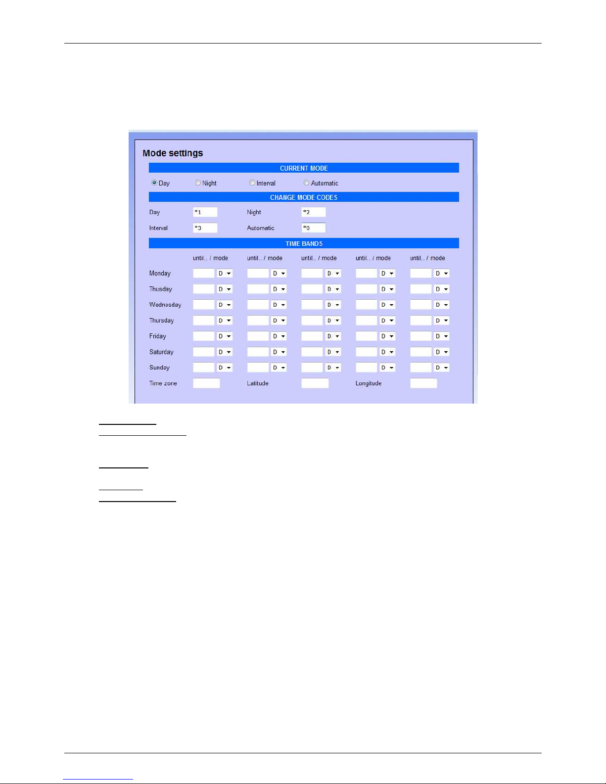
TEMA TELECOMUNICAZIONI SRL
Doorphone AA-560
MAS-AA560-REV04EN Page 43 of 65
9.6. Set of the operating mode
In the operating mode, it is possible to set the mode to DAY / NIGHT / INTERVAL, either manually or automatically
(following time slots per week). This page is also configured to change the codes to the remote phone and
coordinates the installation (used to relay Twilight mode 2, see par. 9.7):
• Current mode: allows you to set the current mode of operation.
• Change mode codes: enter the codes to change it remotely (from any internal phone, call the door phone
and, at the answer, via DTMF type the code corresponding to the selected mode). The codes must consist
of 2 characters.
• Time bands: in the case of automatic operation, it is possible to enter up to 5 bands per day. If a field is left
blank, it is unused so the band corresponding to the previous
• Time zone: time zo ne of the location where the installation is made (+1 for Italy)
• Latitude/Longitude: Geographical decimal coordinates relative to the installation site. Can be retrieved
easily from the internet (eg www.mapcoordinates.net/en)
The time zone and the geographical coordinates are needed in the case of activation of relay 2 in "Twilight" mode
(see par. 9.7).
Page 44
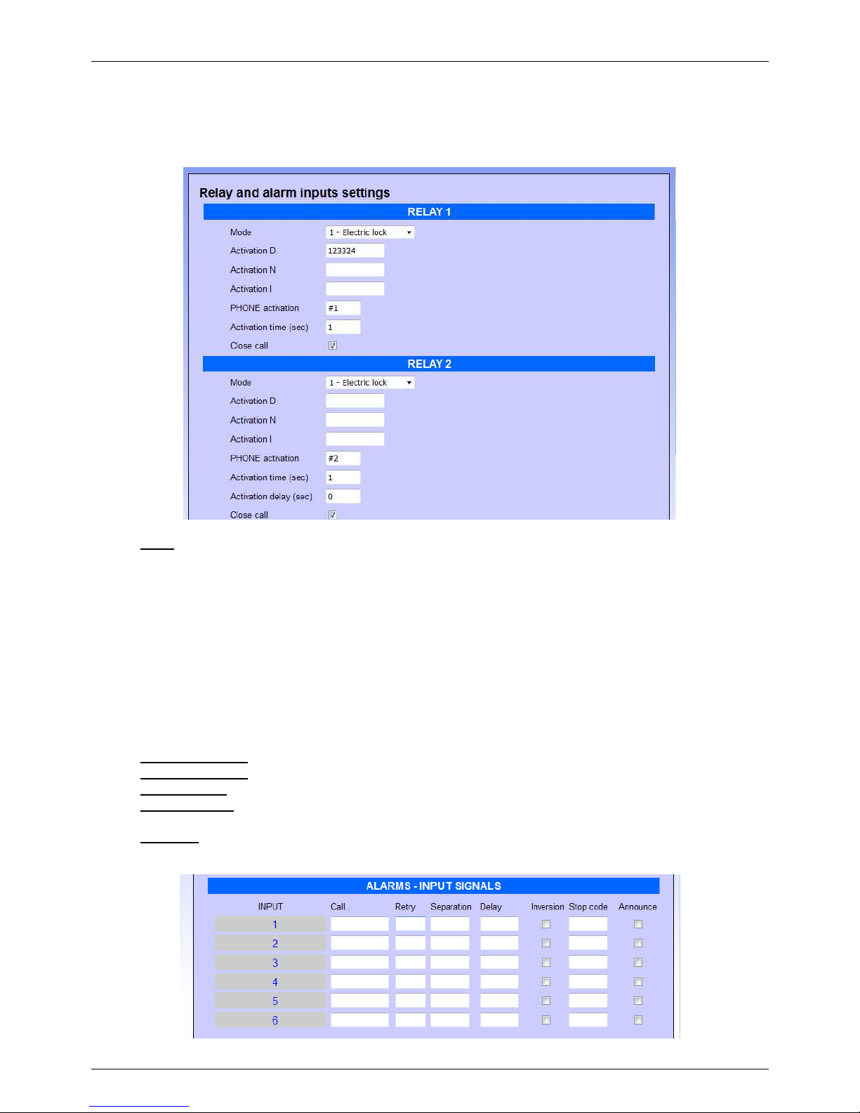
TEMA TELECOMUNICAZIONI SRL
Doorphone AA-560
MAS-AA560-REV04EN Page 44 of 65
9.7. Relay and input settings
On this page it is possible to choose the operating mode of the two internal device relays and the operating mode
for external inputs:
• Mode: sets the function to be associated to the relay. It is possible to choose between:
1 Electric lock: is activated only upon receiving the activation code.
2 In call: is activated when a call is in progress and until the door phone does not come back to idle
3 In call + timer: it activated when a call is in progress and for the activation time
4 Pressure button: you press any key relay is activated for the time set
For the only relay 2
5 After relay 1: When you operate the relay 1, relay 2 is activated also for the time set
6 Twilight: In this mode the relay is activated 30 minutes before sunset and 30 minutes after sunrise.
The calculation of sunrise and sunset is done automatically by the system based on the current
time and location of the installation (the exact time should be obtained from the internet).
• Activation D - N - I: enter here any sequence to dial, from the outside, to activate the corresponding relay
• PHONE activation: relay activation code to dial from the extension of the PBX (2 characters required)
• Activation time: activation time of the relay
• Activation delay: for relay 2, after how many seconds you have to turn with respect to the activation of relay
1 (if set in "after Relay 1")
• Close call: by setting this option, your call is immediately hang up when the relay is activated
Page 45

TEMA TELECOMUNICAZIONI SRL
Doorphone AA-560
MAS-AA560-REV04EN Page 45 of 65
• Call..: number or IP address of the phone to contact when the alarm condition is triggered. The input could
be also used as “door opener”: enter the number of the relay preceded by #. For exampe #1 activate the
relay 1, #2 activate the relay 2. The activation time is the one entered in the activation time filed.
• Attempts: number of call attempts (ma x 999)
• Separation: separation, in seconds, between a call attempt and the other (max 999).
• Delay: it is the minimum time, in seconds, before validating the input. It could be useful, for example, to
mask an open door switch. Supposing the maximum time of a pedestrian gate is 30 seconds, at the end of
this time (if the switch would be still active) an alarm will be send to the reception.
• Inversion: the contact is normally open and the alarm occurs at the closing of the same. Enabli ng this flag it
is possible to instruct the device to behave in the opposite way (the contact is normally closed and the
alarm occurs at the opening).
• Stop code:
:
code to dial on the phone calling to accept and acknowledge the alarm (max 3 digits).
• Announce: whe activating this input, a prerecorded message will be played on the speaker. See messages
management.
In the screenshot are represented up to six inputs, but only the first three are available on this model, other fields
have no function. For each input is assigned a different message that will be played during the call. By default a
neutral message is played ("Alarm 1", "Alarm 2", etc.) but the text can be customized (see par. 9.10).
Page 46
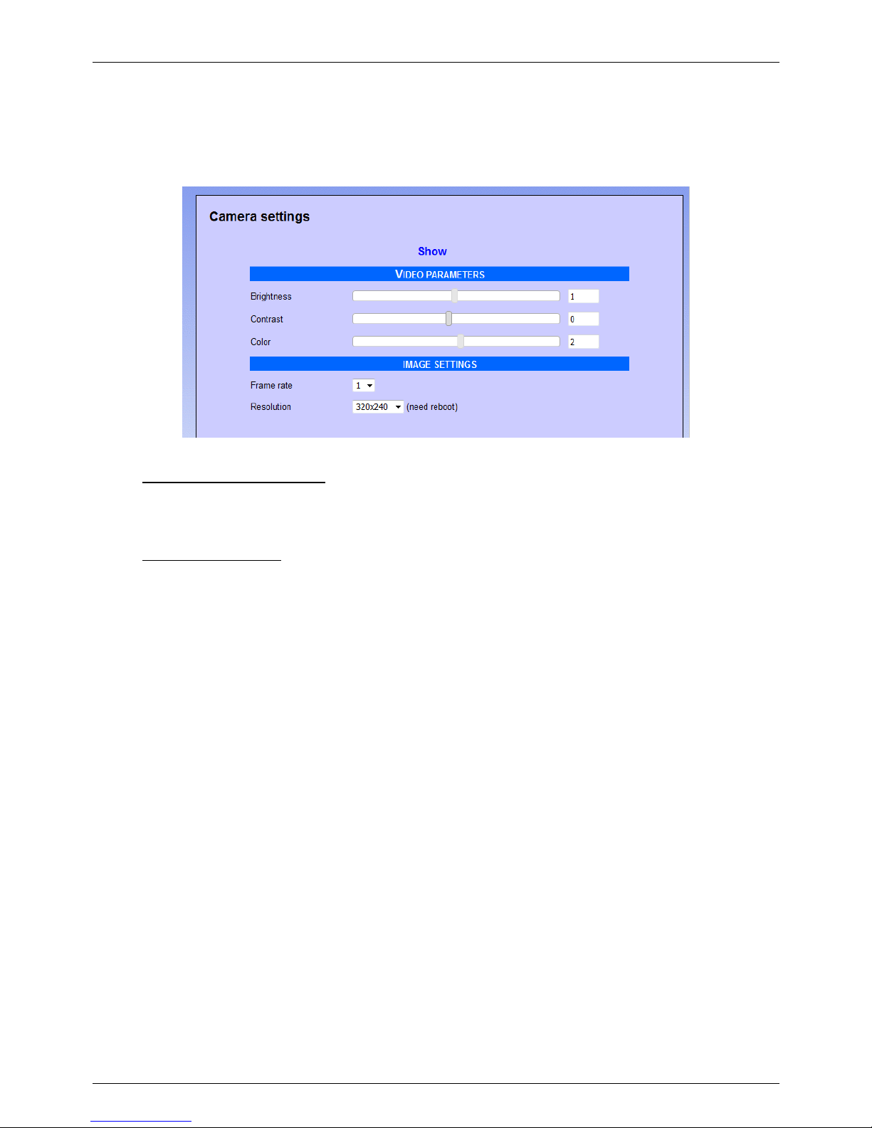
TEMA TELECOMUNICAZIONI SRL
Doorphone AA-560
MAS-AA560-REV04EN Page 46 of 65
9.8. Camera
This programming page is also available in the base version of the device, but it obviously affects only on the
version with camera (AA-560C):
• Brightness, contrast and color: can be adjusted to fit the i mage to your needs, but generally the default
values are already the most suitable for the best vision (the camera is also equipped with an automatic
brightness adjustment mechanism that, within certain limits, is able to compensate the light variations
during the day).
• Frame rate, Resolution: Images per second (frame rate) affects the vision of the video in streaming mode.
The video displayed in conversation, however, will be adapted to the workload of the internal CPU and
generally ranges from 1 to 3 images per second. The change of the video resolution will require a restart of
the device. It is generally recommended not to use high resolutions or high frame rates to not take up too
much communication bandwidth, at the expense of audio quality.
The "Default" button allows to restore the optimal factory values.
Page 47
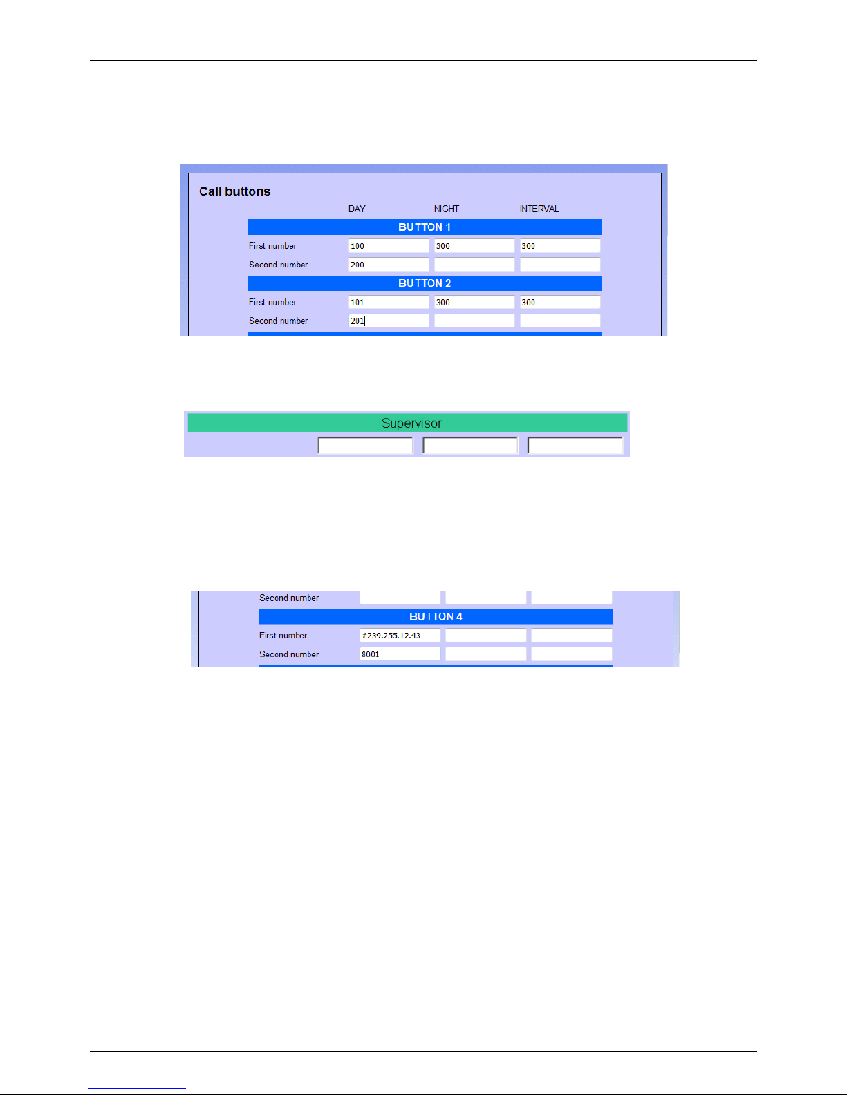
TEMA TELECOMUNICAZIONI SRL
Doorphone AA-560
MAS-AA560-REV04EN Page 47 of 65
9.9. Call buttons
The basic configuration of AA-560 comes with 1 call button. The configuration page of the keys, however, is
complete and allows you to configure both the version with 12-button expansion that the version with numeric
keypad.
For each key, it is possible to enter for each mode of operation (day, night, interval), up to 2 contact numbers. If the
software is unable to contact any of the numbers programmed, it is possible to transfer the call to another number,
programmed in the "Supervisor":
or the cycle ends (there is no one in company that can handle the request).
Sending Multicast audio: it is possible to program each button to activate the function of audio stream sending
rather than performing a normal telephone call. In this case you must enter the address of Multicast preceded by #
in the field "First number" of the Day mode, and in the "Second number" the port number, for example:
By pressing the keys programmed i n this way, the audio captured by microphone is immediately sent to the
programmed address stream. Sending will stop when the button will be released.
NOTE: because AA-560 has only one call button, only “Button 1” of this programming window has sense to be
configured for Multicast streaming send. In this case, however, it could not be possibile to make calls from
Doorphone to PBX, but it could only receive them.
Page 48
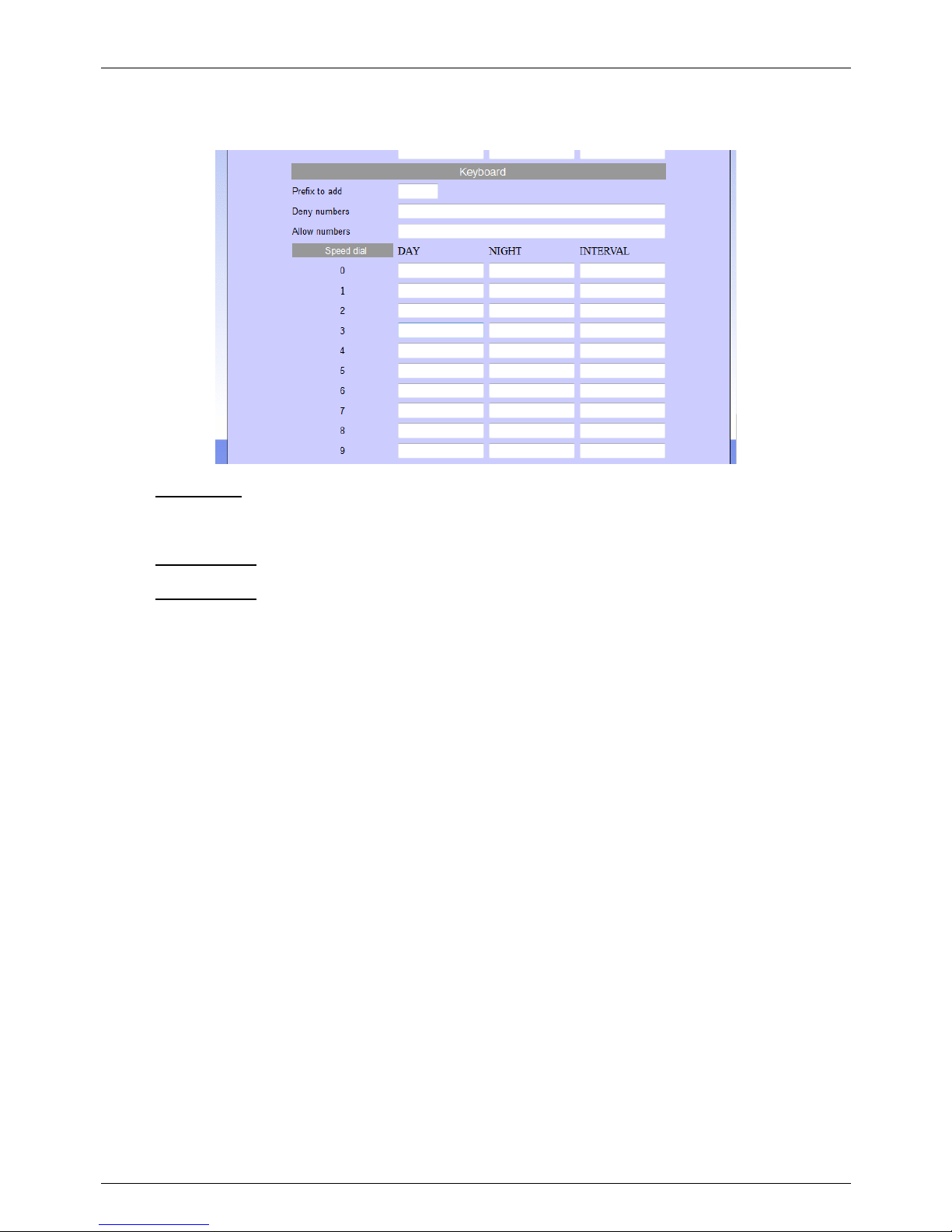
TEMA TELECOMUNICAZIONI SRL
Doorphone AA-560
MAS-AA560-REV04EN Page 48 of 65
Finally, for a Doorphone equipped with a numeric keypad, it is possible to configure:
• Prefix to add: number or group of numbers precede any selection made by the caller. This allows you to
not publish outside the true internal numbering (for example, the numbers may be from 2200 to 2250, but
the legend wi ll get numbers that can be reached from 00 to 50, by inserting 22 as a prefix) or to prevent the
user can enter an unwanted prefix (for example '0 'to access the trunk line).
• Deny numbers: It is possible to enter a list of numbers to block, separated by ",". Useful to prevent from
unwanted numbers intercom calls can be.
• Allow numbers: Similarly, it is possible to enter only the numbers in this list are allowed. Any other number
can not be contacted.
Page 49
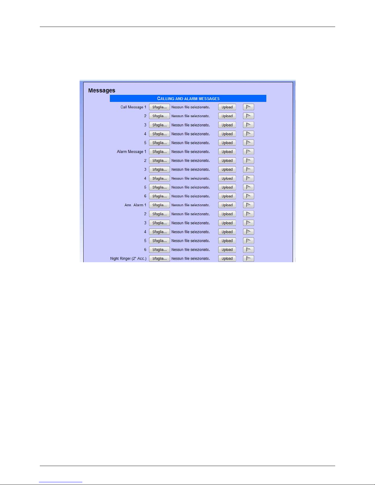
TEMA TELECOMUNICAZIONI SRL
Doorphone AA-560
MAS-AA560-REV04EN Page 49 of 65
9.10. Messages management
In this window it is possible to change/listen to the messages for “Calling”, “Alarms”, “Announcement” and “Ringer”.
Memory contains a default message for each position, the user can change any of them and the messages format
must be WAV PCM 8 kHz, 16 bit, mono.
“Call message”, from 1 to 5, can be reproduced when one of the call button is pressed. The activation and
deactivation of the message is done remotely, directly from an extension phone. It is possible to enter up to 5 wav
messages to be chosen later in the combination of key presses presses.
“Alarm messages”, one for each input, are reproduced to the called telephone number configured in the alarm input
(from 1 to 6): when the called answers, the message is played continuosly, until the user enters the stop code or a
timeout expires. “SIP Alert Call Button” function.
“Ann. Messages”, also one for each input, are reproduced on the local speaker when the relative check in the
alarm mask is selected (see par. 9.7) and the input is active. The message is played before calling. It is possible to
play each message also during a call (see ahead) using a particular code.
At the end, the “Night ringer” is played on the local speaker when a call is received on the second SIP account, if
programmed (par. Errore. L'origine riferimento non è stata trovata.).
How to activate the call messages
To activate / deactivate a call message, you need to call the system and its response dial the programmed code
followed by key, and so message: for example, if the activation code was set to ##, to turn on the key 1 as the Day
message 3 should dial the sequence "## 0103".
NOTE1: In the base version, it is possible to upload messages of length of 16 seconds. For longer messages you
need to enter a license extension in the system page.
NOTE2: Standard messages in the supply of the system (unless specially requested custom) are those listed
below:
MSG1: “La chiamata è stata inoltrata, attendere prego”
Page 50
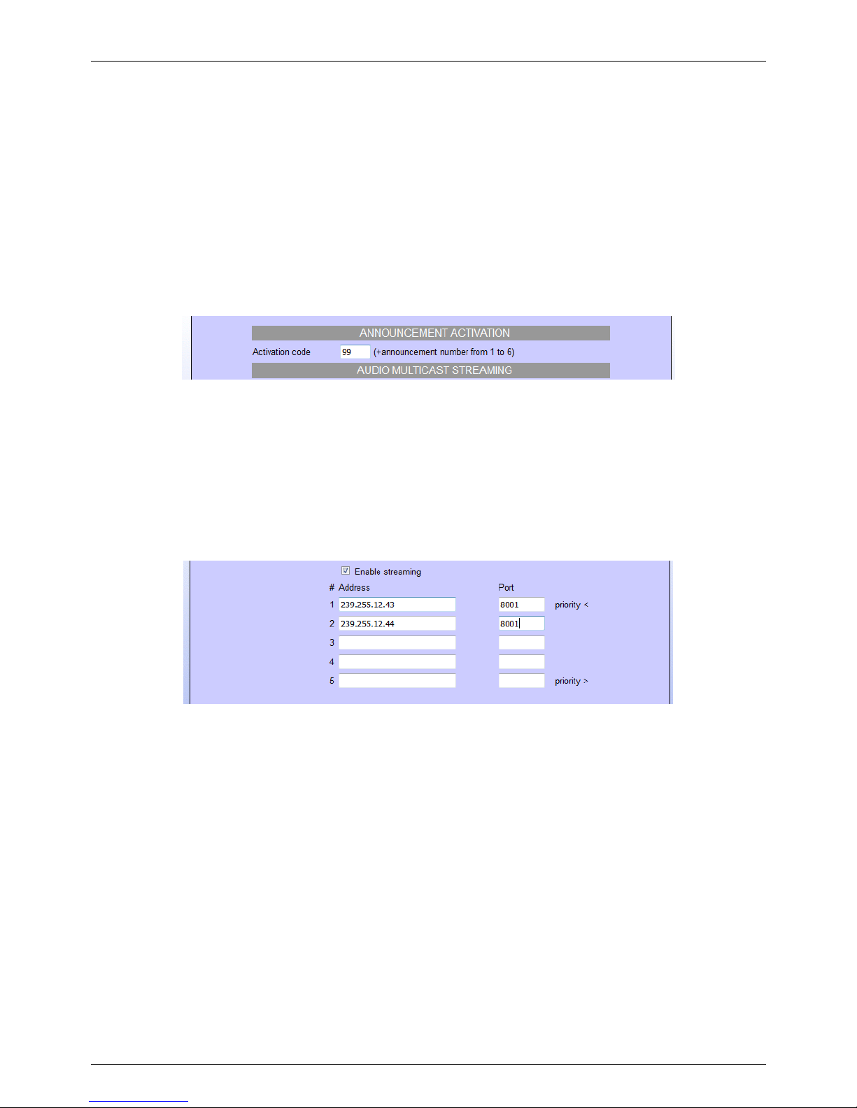
TEMA TELECOMUNICAZIONI SRL
Doorphone AA-560
MAS-AA560-REV04EN Page 50 of 65
MSG2: “Your call has been forwarded, please wait”
MSG3: “La chiamata è stata inoltrata, attendere prego, Your call has been forwarded, please wait”
Messages related to alarms by codes are rigidly associated.
ALR1: “Alarm 1”
ALR2: “Alarm 2”
...
ALR6: “Alarm 6”
How to active an announcement by telephone
As see before, announcement messages can be played when the corresponding input changes. It is also possible
to make the same thing during a telephone call. In the filed “Announcement activation code” insert the code for this
function:
In the example the code is “99”. Simply, follow the announcement number after this code (from 1 to 6). When the
play starts, the call is hung up (internal extension will be freed). Attention please: the message could also be very
long, so if you need to interrupt it for some reason, simply call the system, the message will be stopped to make
room for new communications.
Audio Multicast streaming
By enabling this feature, AA-560 will listen to the specified address / port, and can reproduce on its speaker any
received audio streaming. This function has a lower priority than the normal telephone operation of the system
(outgoing or incoming calls will block or prevent the reproduction of the audio stream).
It is possible to configure up to 5 multicast addresses, each one with an higer priority than the previous. In the
above example, there are two addresses. The first (..43) could be used to play music from a PC. The second (..44)
could be an announcement from a special phone. Generally the music is always on but will stop immediately when
an announcement from the phone is received.
It is possible to configure up to 16 multicast addresses, each one with an higher priority than the previous. In the
above example, there are two addresses. The first (..43) could be used to play music at low volume from a PC. The
second (..44) could be an announcement from a special programmed phone for Multicast with an higher volume.
Generally the music is always on but will stop immediately when an announceme nt from the phone is received.
Page 51
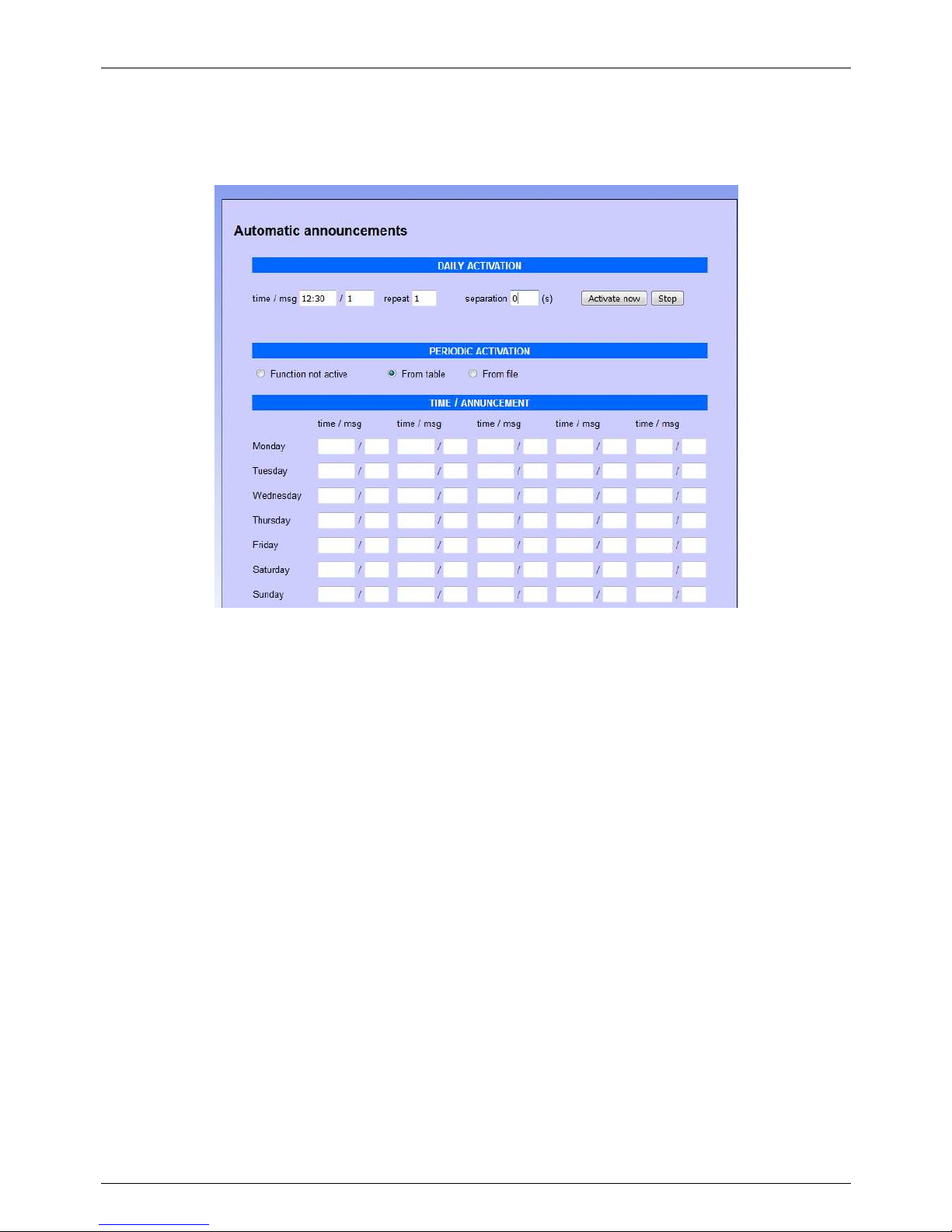
TEMA TELECOMUNICAZIONI SRL
Doorphone AA-560
MAS-AA560-REV04EN Page 51 of 65
9.11. Automatic Announcements
It is possible to program the diffusion of announcements at pre-set times, which can take place on the local
speaker or streamed to other devices.
Daily activation:
it is possible to automate the diffusion of a daily announcement (which will take place at the set time) for each day.
It will be reproduced for the number of repetitions, with separation between a message and the other given by the
number of seconds set. It is also possible to manually activate the message (with the "Activate now" button) or stop
playback (with the "Stop" button). If the manual activation mode is only used, it is not necessary to indicate the start
time.
The shown message is one of the 6 alarm announcement messages that can be found in the "Message
Management" section.
Periodic activation from table:
if you activate this function, it is possible to indicate in the table below, for each day of the week, up to five different
times, for each of which it is possible to specify one of the six pre-recorded announcement messages.
Page 52
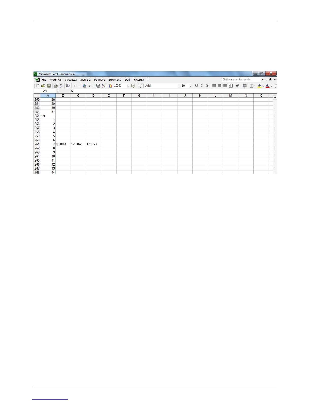
TEMA TELECOMUNICAZIONI SRL
Doorphone AA-560
MAS-AA560-REV04EN Page 52 of 65
Periodic activation from file:
it is possible to upload a text file in "csv" format (easily editable with "Excel") that contains, for each day of the year,
up to 5 times in which to make the announcement diffusion. To compile the file simply download the default one
already present (and empty), modify it and re-upload it (do not change the written months, are used by the device
to index itself in the document):
In the example it was indicated that on September 7th (every year) the message 1 should be reproduced at 09.00,
message 2 at 12:30 and message 3 at 17:30 .
Streaming
Finally it is possible to reproduce the messages indicated not towards the local speaker but to a streami ng
multicast address. To do this it is sufficient to insert, after the message number, the letter S followed by the
multicast channel number programmed in the "Call buttons" mask (see description "Sending Multicast audio"). For
example, 1S2 means that the message 1 must be reproduced in streaming to the address programmed on key 2.
NOTE1:
the playback volume, in the case of diffusion on the local speaker, is the one set as the ringer volume in the "SIP
Parameters" programmi ng screen. In the case of streaming playback, the volume is given by the volume of the
multicast channel programmed in reception.
NOTE2:
since the device does not have its own internal clock, the automatic diffusion of messages can take place only if it
is synchronized with a time server (which can be one into the local network or any other on the internet, see the
"Network parameters" ).
Page 53
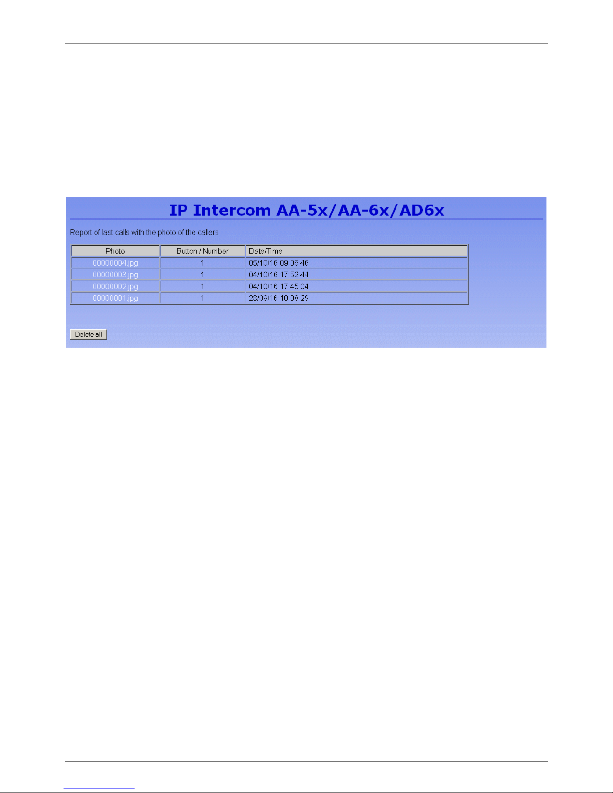
TEMA TELECOMUNICAZIONI SRL
Doorphone AA-560
MAS-AA560-REV04EN Page 53 of 65
9.12. RFID management
AA-560 is not equipped with RFID reader, however, being the programming software common to all hardware
versions, this mask is still usable, but any configuration in this page will not be usefull for the operational work of
the device.
9.13. Calls report
For the version with the camera (AA-560C), it is possible to have a call report (ie each time a visitor presses a
button, the device saves the event, see par. 9.5), in each of it will be shown the date/time of the event, the dialed
number and the picture of the framed area. The list is presented starting from the most recent call:
The list can contain up to 250 entries, after which the older are deleted.
To keep a history list of events that goes beyond this limit, enable the function of sending e-mail with each press of
the button by the visitor, the image will be sent as an attachment and you will create a list of all accesses
performed.
Page 54
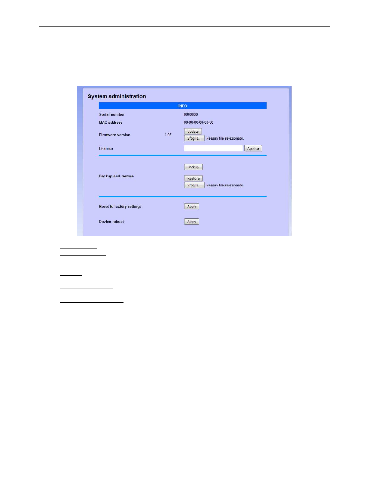
TEMA TELECOMUNICAZIONI SRL
Doorphone AA-560
MAS-AA560-REV04EN Page 54 of 65
10. MAINTENANCE
10.1. System
On this page it is possible to check the current firmware version, update software, and backup / restore the system
configuration:
• MAC address: is the physical address assigned to the network interface.
• Firmware version: displays the currently installed version of the program. It is possible to upload a different
version (possibly provided by the technical support of TEMA) using the Browse / Update. Once you've
uploaded the new version, the device must be restarted.
• License: enter in this field the license key to activate any additional services (such as the use of messages
over 16 seconds).
• Backup and restore: it is possible to save the current settings to restore them in case of a programming
error or device replacement.
• Reset to factory settings: all settings are lost and reset to factory defaults. You are prompted to confirm the
operation.
• Device reboot: reboot as if it were taken away and put back power. Useful in case you have not physically
present in front of the device and it needs to restart it. You are prompted to confirm the operation.
Page 55
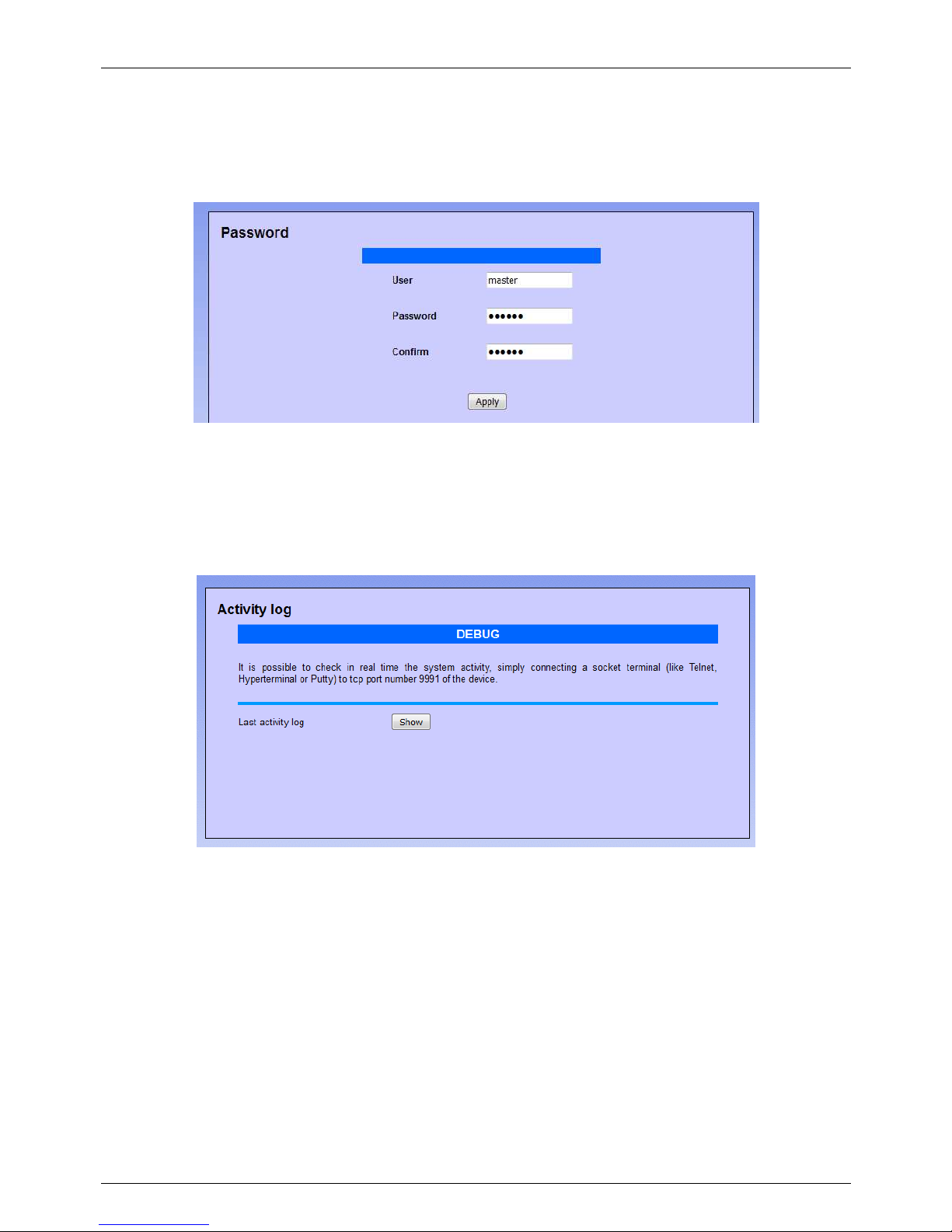
TEMA TELECOMUNICAZIONI SRL
Doorphone AA-560
MAS-AA560-REV04EN Page 55 of 65
10.2. Login credentials
By default, the user name and password for access to the configuration are master/master (lowercase). It is not
possible to have more than one user (there are not hierarchical levels of programming), but it is possible to change
the login credentials:
The password should be introduced twice for confirmation. If for any reason your password was forgotten, it is
possible to reset it to the default closing a jumper inside the device (see par. 9.2).
10.3. Diagnostic log
To identify small configuration problems, it is possible to activate a diagnostic summary on the activity of the two
VoIP channels of the device. Simply connect via TCP port 9991 with Telnet or a terminal like Hyperterminal:
It is also possible to view the history of activities for each module by clicking "Last log". The log is deleted when it
exceeds the size of about 2 MB.
Page 56
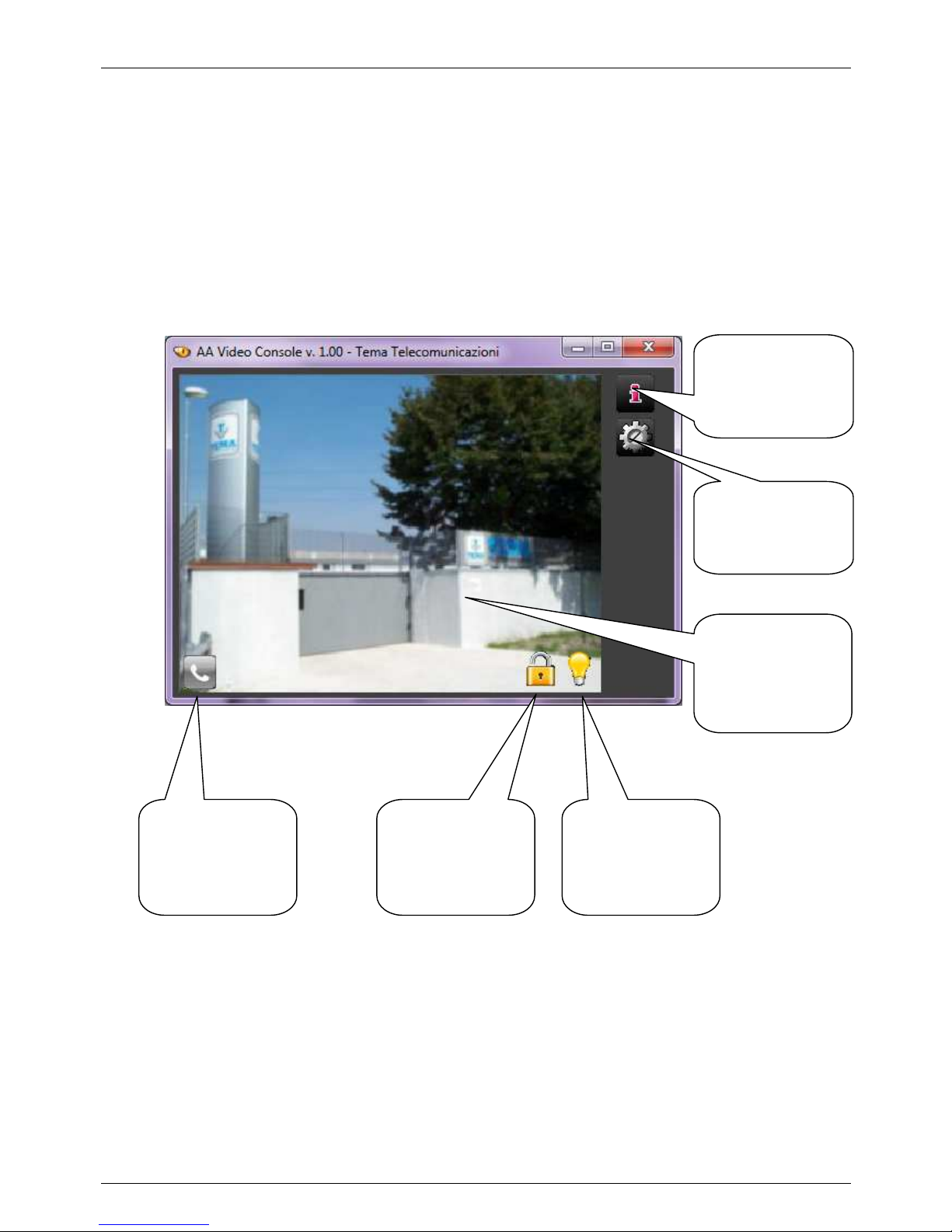
TEMA TELECOMUNICAZIONI SRL
Doorphone AA-560
MAS-AA560-REV04EN Page 56 of 65
11. PRESENTATION AND USE OF THE PROGRAM "AA Video Console"
It's a program that comes along with the Doorphone and can be installed on a PC with Windows XP operating
system or later. The program allows you to see the area framed by the built-in camera of AA-560, to operate the
device relays from the program window and then lets you talk with the visitor if the PC where it is installed has a
sound card with speakers and microphone. It is possible to view up to 16 Doorphones at the same time (to be
chosen during setup) and also to control up to 16 gates with a single computer.
Locate the program in the directory on the CD-ROM supplied ("AAVideoConsole / setup.exe") and install it.
11.1. Presentation
This is the main window of the program. The commands available are described in the text bubbles.
Access to the
configuration
page
Version
information
Button to drive
relay 1 (opening
electric gate)
Button for direct
calls to
Doorphone or
call status
Button to drive
relay 2 (lighting
or second gate)
Area captured by
the built-in
camera
Page 57
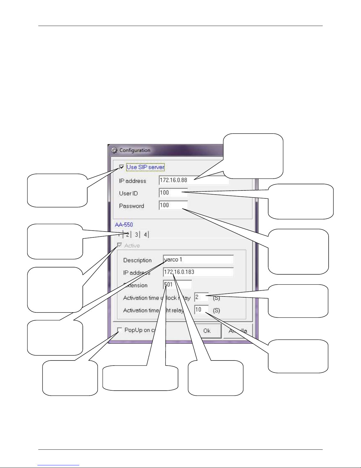
TEMA TELECOMUNICAZIONI SRL
Doorphone AA-560
MAS-AA560-REV04EN Page 57 of 65
11.2. Software configuration for SIP Server mode
The video stream that the program will show comes directly from the data stream of the IP address of AA-560C.
The audio of the conversation with AA-560C or the voice communication with the visitor is a normal VoIP
communication between two SIP phones. In this case, one of the interlocutors will be AA-560C and the other one is
the PC with the "AA Video Console".
To make sure that a visitor can communicate through AA-560C with the PC with this program, you must set the
number assigned to "AA Video Console" also in the parameters of AA-560C (see par. 9.9 "Call buttons" ).
By clicking the button which gives access to the configuration parameters of the program, the following window will
be showed:
It is possible to configure up to 16 gates (by activating the check "Active"), the display of the main page of the
program will be adapted based on the number of Doorphones activated.
Passord
authentication of
"AA Video
Console"
on the PBX
Tick to obtain the
SIP Server mode
IP address of
your VoIP PBX
where the
software will
register
Phone number
identifier of "AA
Video Console"
on the PBX
Activation time of
relay 1 (lock)
Extension of AA-560C
IP address of
AA-560C
Activation time of
relay 2 (light)
Gate
description
Number of the
Doorphone to
be configured
Enables the
display of the
gate (required
on the first)
PupUp during
a call
Page 58
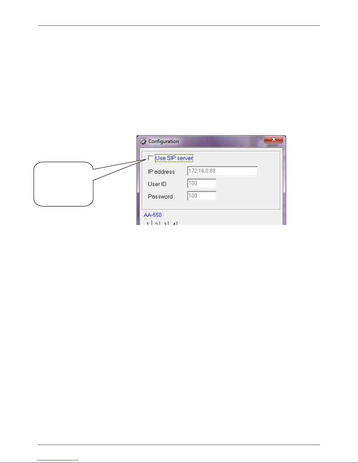
TEMA TELECOMUNICAZIONI SRL
Doorphone AA-560
MAS-AA560-REV04EN Page 58 of 65
11.3. Software configuration for Peer-To-Peer mode
In this configuration mode, the software does not register on a PBX, but makes calls directly to the address
specified in AA-560C. So the video stream and the audio of the conversation with AA-560C will take place without
the intervention of the PBX (the two devices doesn’t need to be registered to any existing SIP Server).
In this configuration, one of the interlocutors will be AA-560C, the other is the PC with the "AA Video Console".
To make sure that a visitor can communicate through AA-560C with the PC with this program, you must set the IP
address of the PC in the parameters of AA-560C. By doing so AA-560C will forward the call to the IP address of the
PC where "AA Video Console" is installed (see par. 9.9 "Call numbers").
Do not check for
the Peer-to-Peer
mode
Page 59
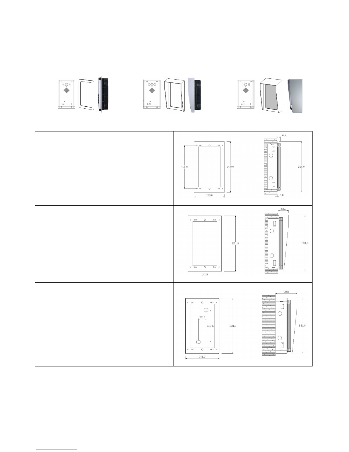
TEMA TELECOMUNICAZIONI SRL
Doorphone AA-560
MAS-AA560-REV04EN Page 59 of 65
12. INFORMATIONS FOR THE WALL INSTALLATION OF THE SYSTEMS
It is possibile to install AA-560 systems and its expansions in many ways. These ways can be different based on
the fact of using only one system or one system with one or more expansions or using the protection accessories
like frames, shields or full box. This informations make a guideline about the correct systems installation.
Single system
If only one flush base system (AA
-
560 in different
versions) is used, it is mandatory to recess his metallic
back box to the wall, then securing the front panel.
To facilitate the finishing and the system/wall junction
there is the possibility to use the wall cover metal frame
accessory called AA-549-C1.
If the accessory is not provided, the front panel of the
system with its frame will simply go directly to the wall,
fixed to the metallic recessed back box.
To have a rain protection it is possibile to install the
system AA-539 with the AA-549-T1 accessory (frame
complete of shield).
If the AA-549-S1 accessory is used (complete stainless
steel box with shield for external wall mounting), it is not
necessary to recess the metallic back box to the wall. In
fact all the system is fixed on the wall. First is placed
the box, then the rest of the system.
Page 60
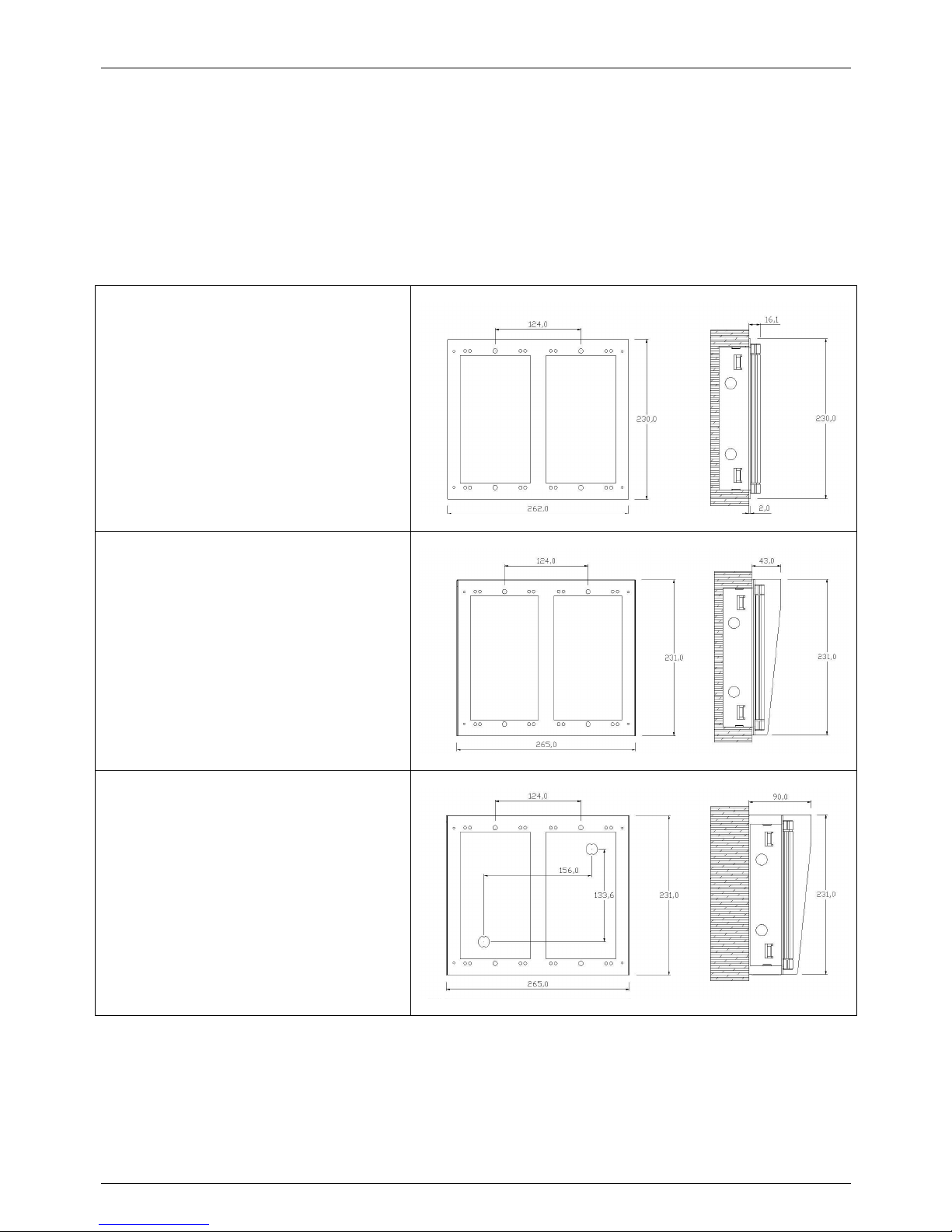
TEMA TELECOMUNICAZIONI SRL
Doorphone AA-560
MAS-AA560-REV04EN Page 60 of 65
Double system, composed of two elements, base system plus one expansion module
If it is used a AA-560 system with one expansion module, for example one AA-539K or AA-539R, please follow the
next indications.
Provide to recess the metallic back box at the right distance between them. To facilitate the installation, with each
back box is provided a particular tube cable that allows to horizzo ntaly hook the metallic shells side by side, in
order to keep them in the right position to be recessed in the wall. So the tube cable held the function to made
possible the passage of the cables between one back box and the other without having to run other pieces of
corrugated tube.
To facilitate the finishing and the system/wall
junction there is the possibility to use the wall
cover metal frame accessory called AA-549C2 with 2 positions side by side.
If the accessory is not provided, the front
panel of the systems with its frame will simply
go directly to the wall, fixed to the metallic
recessed back box.
Even the shield accessory AA-549-T2 (cover
for protection of 2 systems) is designed to be
put in place on 2 back box previously walled
with the aid of the particolar tube cable
previously described.
When is used the AA-549-S2 accessory
(single full box for 2 systems), it is not
necessary to recess the metallic back box to
the wall. In fact all the system is fixed on the
wall. First is placed the box, then the rest of
the system.
Page 61
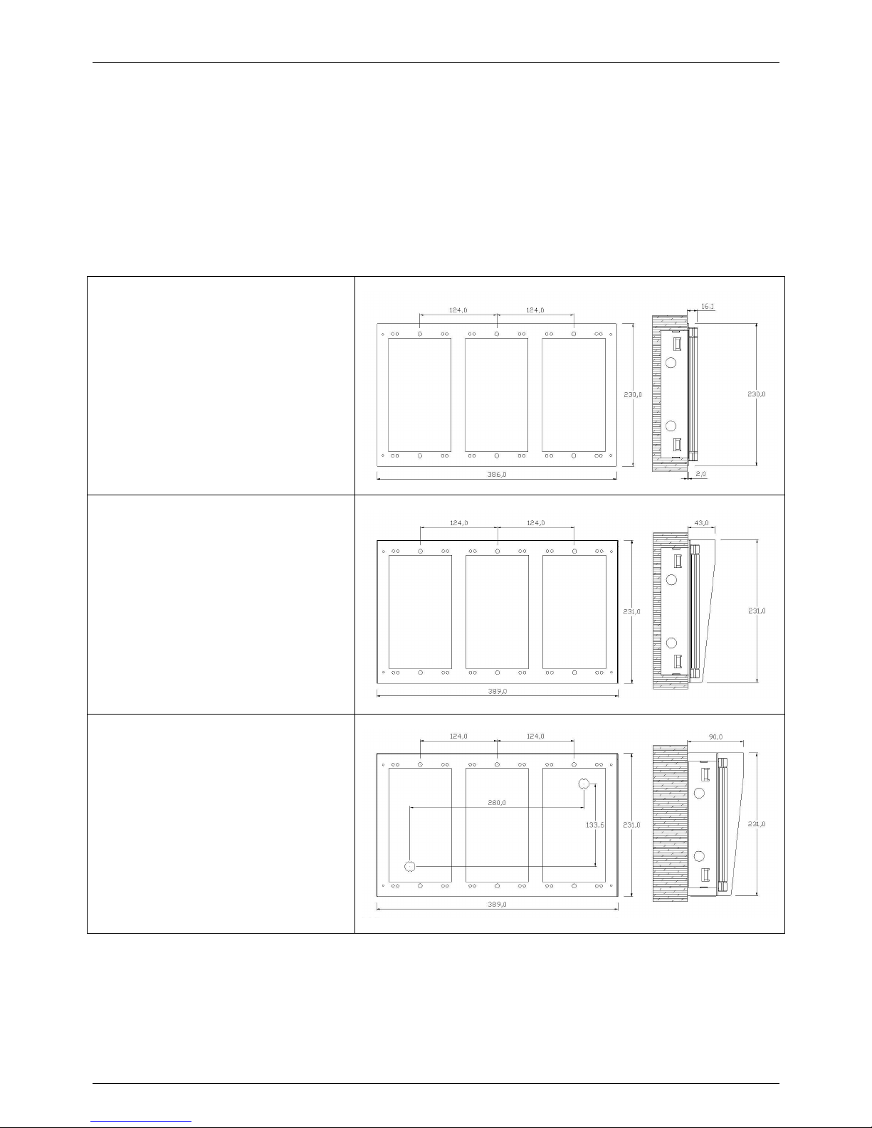
TEMA TELECOMUNICAZIONI SRL
Doorphone AA-560
MAS-AA560-REV04EN Page 61 of 65
Triple system, composed of three elements, base system plus two expansion module
If it is used a AA-560 system with two expansion module, for example one AA-539K + AA-539R, please follow the
next indications.
Provide to recess the metallic back box at the right distance between them. To facilitate the installation, with each
back box is provided a particular tube cable that allows to horizzo ntaly hook the metallic shells side by side, in
order to keep them in the right position to be recessed in the wall. So the tube cable held the function to made
possible the passage of the cables between one back box and the other without having to run other pieces of
corrugated tube.
To facilitate the finishing and the
system/wall junction there is the possibility
to use the wall cover metal frame
accessory called AA-549-C3 with 3
positions side by side.
If the accessory is not provided, the front
panel of the systems with its frame will
simply go directly to the wall, fixed to the
metallic recessed back box.
Even the shield accessory AA-549-T3
(cover for protection of 3 systems) is
designed to be put in place on 3 back box
previously walled with the aid of the
particolar tube cable previously described.
When is used the AA-549-S3 accessory
(single full box for 3 systems), it is not
necessary to recess the metallic back box
to the wall. In fact all the system is fixed
on the wall. First is placed the box, then
the rest of the system.
Page 62
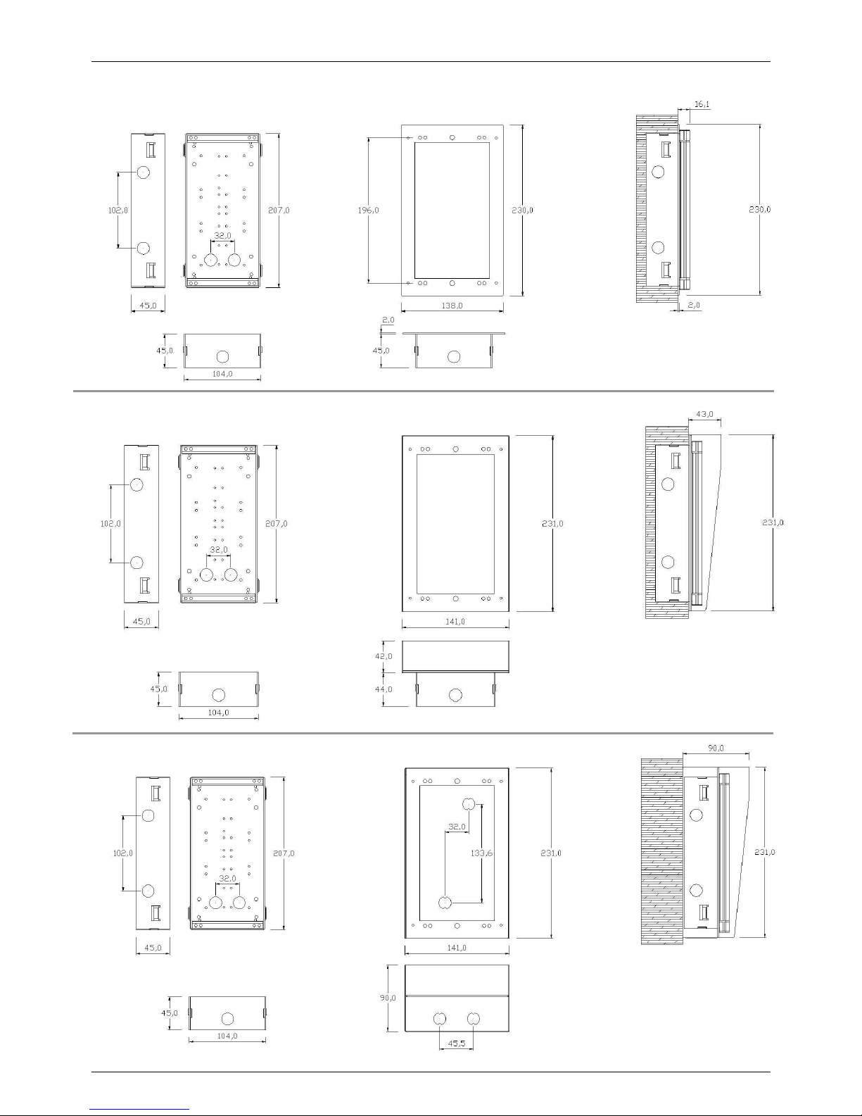
TEMA TELECOMUNICAZIONI SRL
Doorphone AA-560
MAS-AA560-REV04EN Page 62 of 65
Page of the measures for the installation of a single system with the overall dimensions of the various solutions:
Page 63
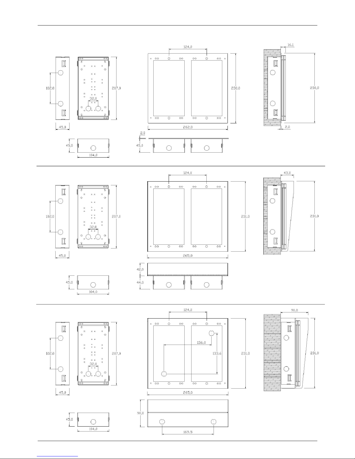
TEMA TELECOMUNICAZIONI SRL
Doorphone AA-560
MAS-AA560-REV04EN Page 63 of 65
Page of the measures for the installation of two side by side adjacent systems:
Page 64
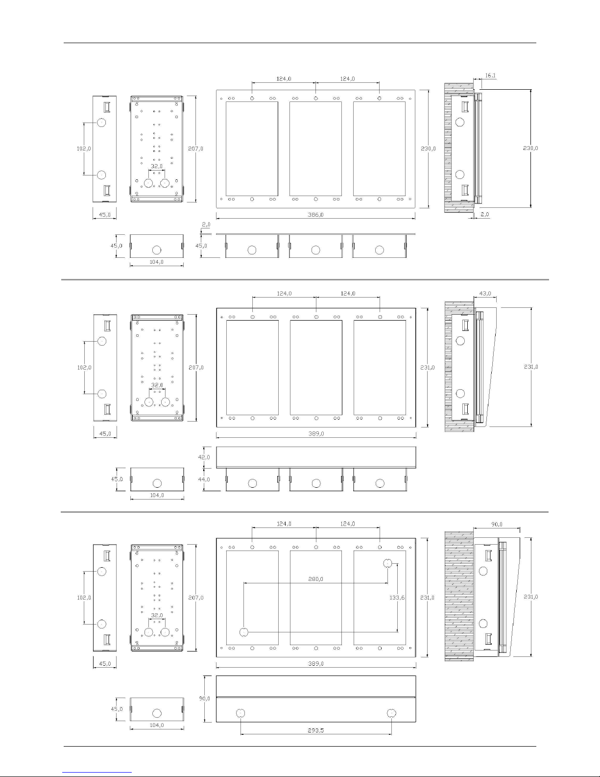
TEMA TELECOMUNICAZIONI SRL
Doorphone AA-560
MAS-AA560-REV04EN Page 64 of 65
Page of the measures for the installation of three side by side adjacent systems:
Page 65

TEMA TELECOMUNICAZIONI SRL
Doorphone AA-560
MAS-AA560-REV04EN Page 65 of 65
REMARKS:
 Loading...