

Page 1
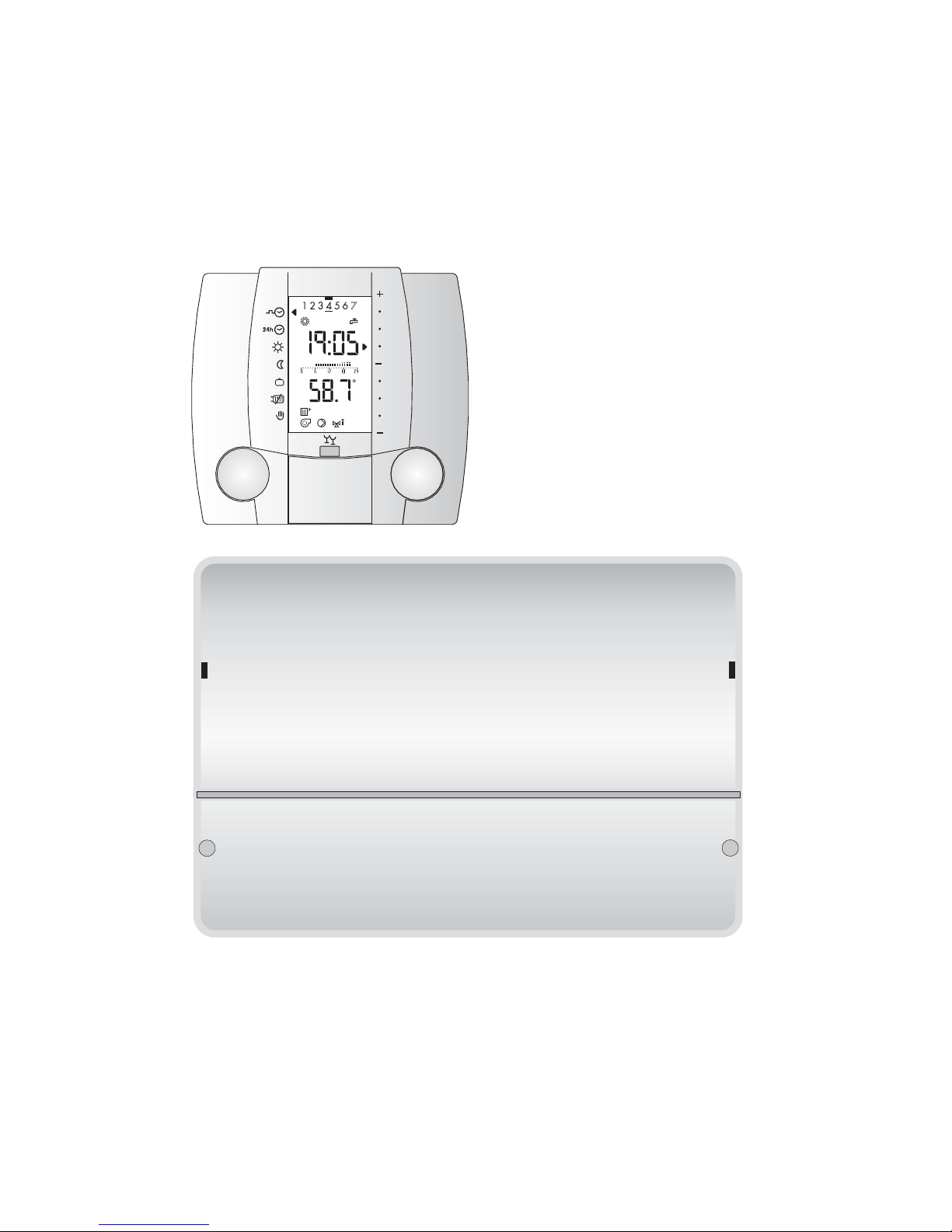
VS 5500 plus
Heating controller
C
Operating manual
Dok. Nr. 111045 33/2007 "entwurf"
Page 2

Contents
Danger
The controller is electrically operated. Incorrect installation or repair attempts
may endanger life due to electric shock.
Installation and start-up of the controller
may only be carried out by trained and
qualified personnel. The controller and
accessories should not be opened.
Repairs may only be carried out by the
manufacturer.
1 Operation with the cover closed .............................................................................. 5
1.1 Select operating mode ................................................................................................ 5
1.2 Set room temperature temporarily............................................................................... 6
1.3 Party function/operating lock ....................................................................................... 6
1.4 Activation of the holiday programme........................................................................... 7
1.5 Temporary interruption of the holiday programme ...................................................... 7
1.6 Activate the clock programme exception day.............................................................. 8
1.7 Heating limit ................................................................................................................ 8
1.8 Manual / emergency operation.................................................................................... 9
2 Operation with the cover open............................................................................... 10
2.1 Setting the date ......................................................................................................... 11
2.2 Setting the clock time ................................................................................................ 12
2.3 Check temperatures and operating mode................................................................. 13
2.4 Temporarily deactivation of room temperature influence.......................................... 13
2.5 Setting the weekly clock programme......................................................................... 14
2.6 Setting the clock programme exception day ............................................................. 15
2.7 Setting the room temperature ................................................................................... 16
2.8 Setting the automatic holiday programme................................................................. 17
3 Settings in the service level ................................................................................... 18
3.1 CLEAR function (reload factory settings) .................................................................. 18
3.2 Setting level 3 - Room temperature control mixed heating circuit............................. 19
3.3 Setting level 3 - Room temperature control direct heating circuit.............................. 21
3.4 Setting level 5 - Warm-water supply.......................................................................... 22
4 Settings in the coded service level........................................................................ 23
5 Constant values ...................................................................................................... 26
Explanation of terms and
abbreviations, page 33
Symbols used
In this document the following symbols
are used:
Danger from electricity!
Important note requiring special attention!
Note/explanation!
2
6 General points ......................................................................................................... 27
6.1 What makes up the VS 5500 plus?........................................................................... 27
6.2 What does the VS 5500 plus control?....................................................................... 27
6.3 Hydraulic .................................................................................................................. 27
7 Dimensions and installation................................................................................... 28
7.1 Installation VS 5511 plus ........................................................................................... 28
7.2 Dimensions VS 5511 plus ........................................................................................ 28
7.3 Installation SR 5811 .................................................................................................. 29
7.4 Dimensions SR 5811 ............................................................................................... 29
7.5 Start-up ..................................................................................................................... 30
7.6 Electrical installation diagram ................................................................................... 30
8 Help in solving problems........................................................................................ 31
9 Technical data ......................................................................................................... 32
9.1 Technical data SR 5811............................................................................................ 32
9.2 Technical data VS 5511 plus .................................................................................... 32
9.3 Sensor resistance values .......................................................................................... 33
9.4 Explanation of terms and abbreviations .................................................................... 33
Page 3
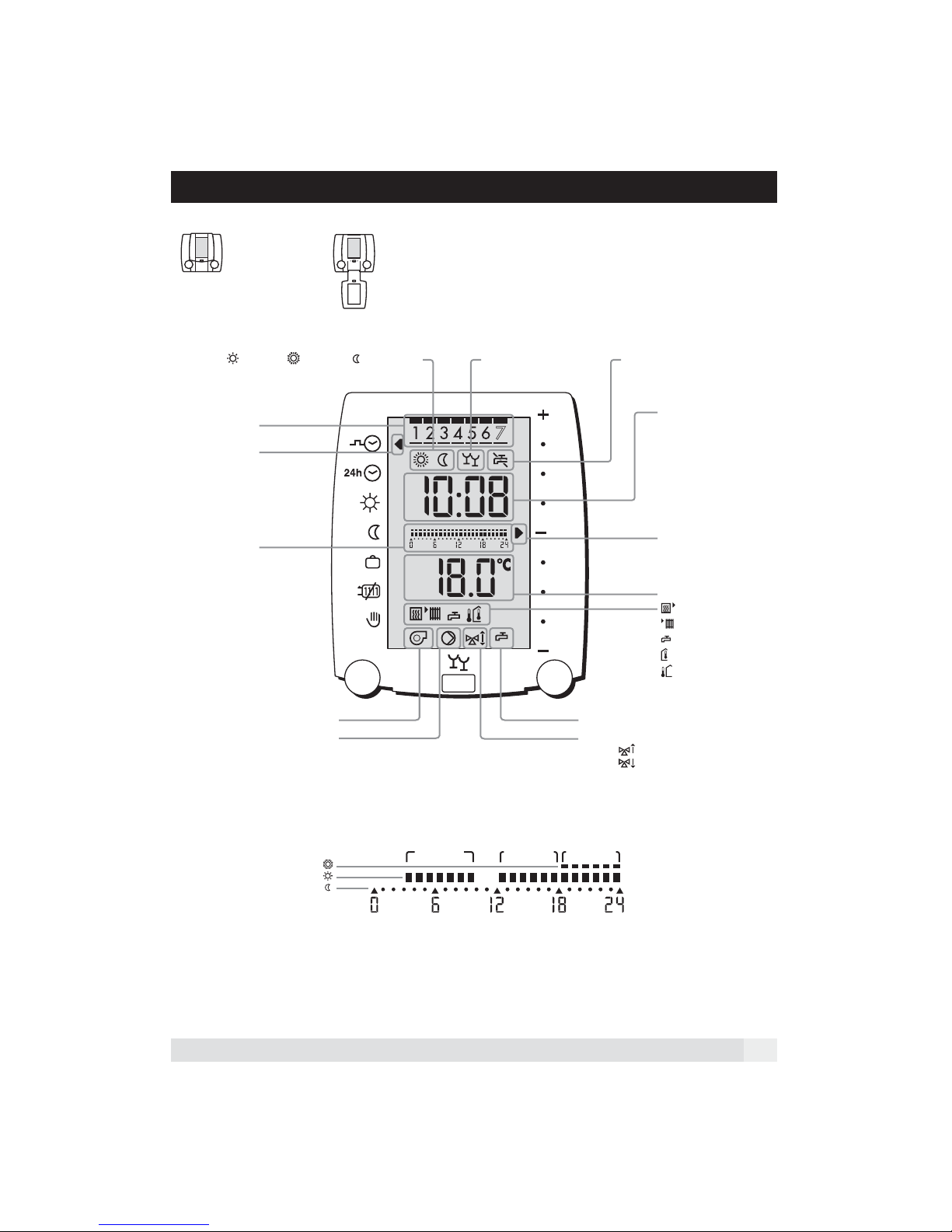
Display und operating elemente
Clapet closed Claped open
desired room temperature:
= normal, = comfort, = reduced
Party function
Domestic hot water production
on/off
Days:
1=Monday
2=Tuesday etc.
Arrow marks the
selected mode
Time bar
temperature-/
time process of the
actual day
Heating circuit pump
Reduced modus
Boiler requirement DHW request
Tendency mixing valve
OPEN
CLOSE
Time bar:
The selected heating program is shown
Comfort modus
Normal modus
b1
Time bloc 1
b2
Time bloc 2
b3
Time bloc 3
Daytime
Roomtemperature
heating mode
adoption
(with the right
rotary knob)
measured
temperatures of:
= Boiler
= Flow
= DHW
= Room
= Outside
3
Page 4

Notes:Display und Bedienelemente
4
Page 5
1 Operation with the cover closed
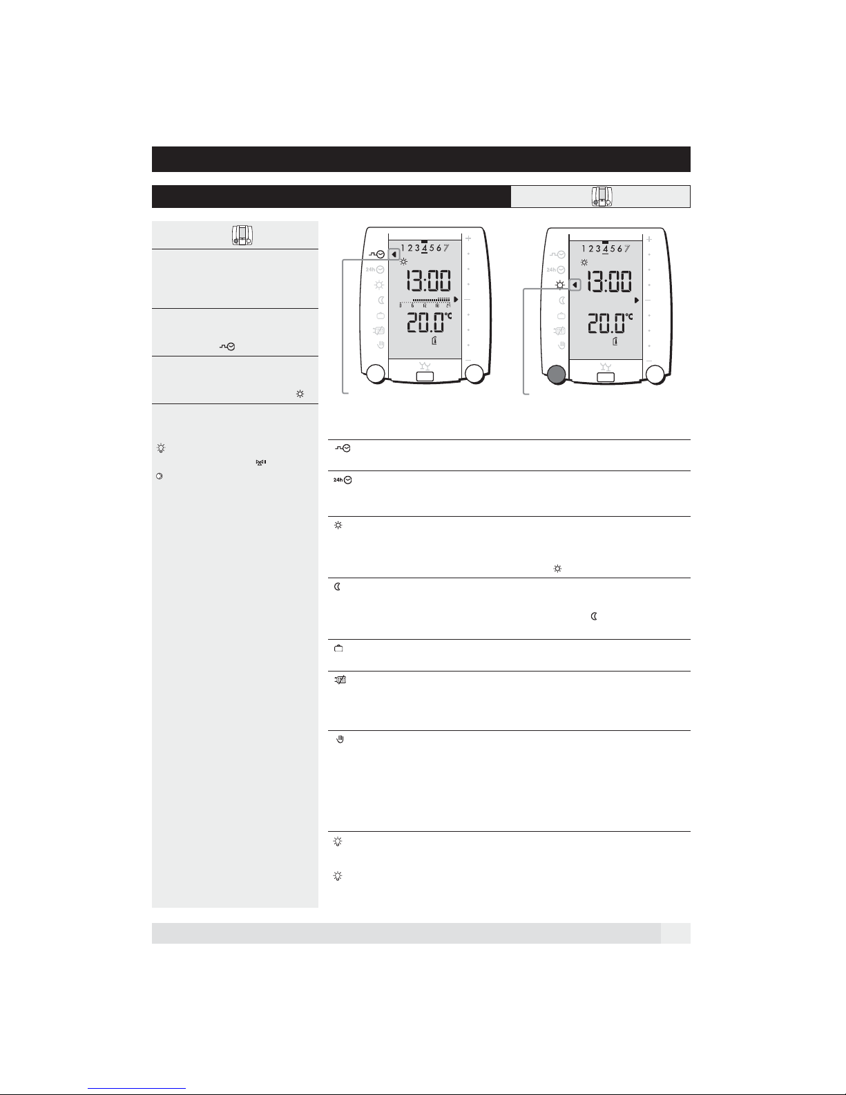
1.1 Select operating mode
Cover closed 12
The required operating mode can be selected using the left rotary knob.
The arrow to the left in the display shows
which operating mode is active.
Example:
1. The arrow marks the weekly clock
programme .
2. In order to change to the operating
mode Heating, the left rotary knob
should be turned to the symbol .
All settings are valid for both
heating circuits, mixed and direct
at the same time!
Weekly clock programme
Operating modes:
Weekly clock programme • Automatic changeover from heating to
Clock programme exception day • After running, the programme returns
Heating • No clock programme
Reduced heating • No clock programme
Holiday • Heating/Warm-water heating OFF
Heating OFF / Summer operation • Heating is OFF
Manual/emergency operation • Heat generator continually ON
A blinking symbol shows that in addition to the current operating mode,
a further function has been temporarily activated.
Warm-water heating is always active parallel to heating in the selected operating
mode and starts earlier by the set time period (factory setting, 60 mins.).
Heating
warm-water heating - reduced operation
automatically to the weekly clock programme
• Heating/warm-water heating is carried
out continuously according to the set
value.
• Reduced heating is carried out according
to the set value
• No warm-water heating
• Frost/room protection function active
• Warm-water heating is active according
to the weekly clock programme.
• Frost/room protection function active
(as per boiler thermostatt setting)
• Heating circuit pump continually ON
• Warm-water heating continually ON
Check boiler temperature thermostat!
Operate the mixer manually!
Request help from an expert!
5
Page 6
1.2 Set room temperature temporarily
Cover closed
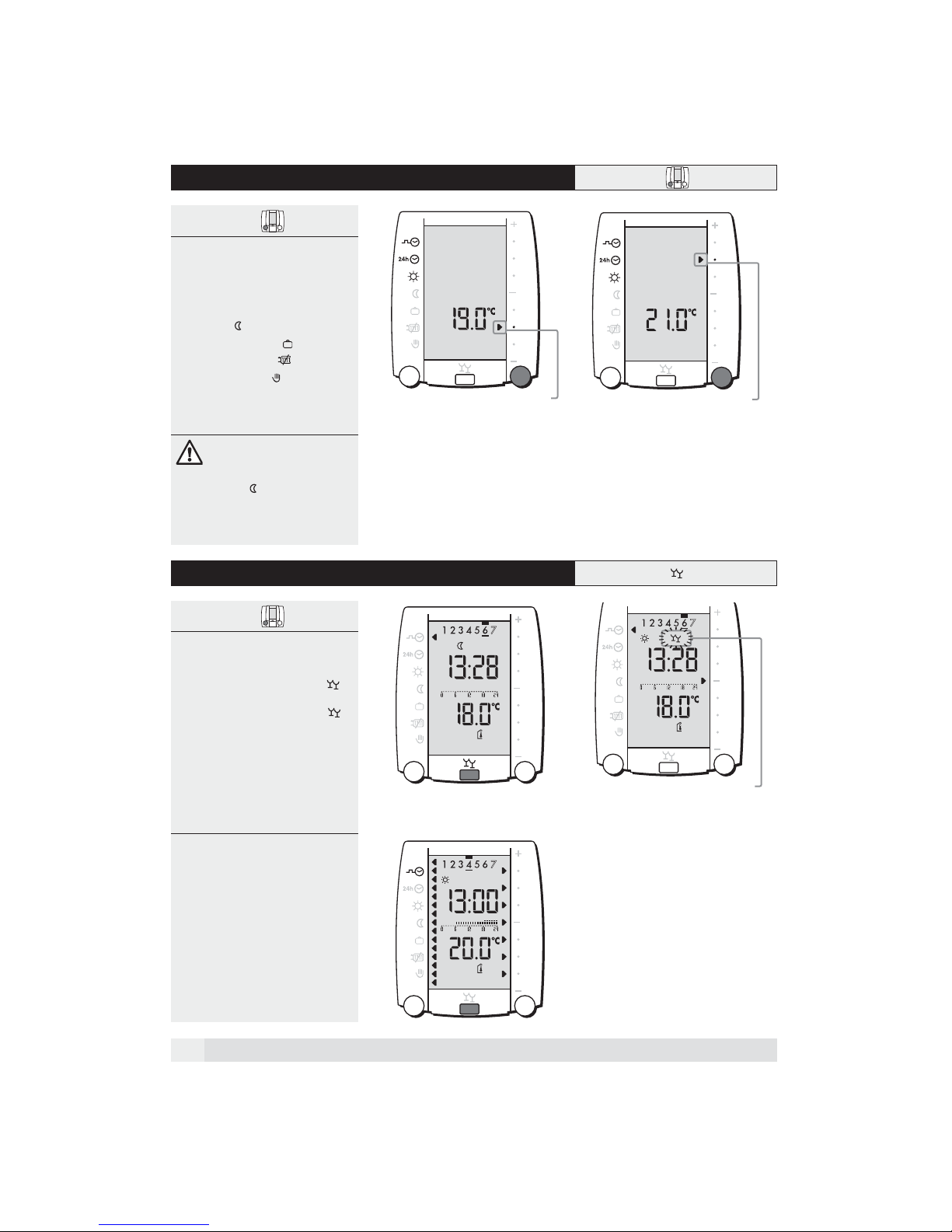
The room temperature can be set temporarily using the right rotary knob.
This adjustment can be made in all
operating modes except:
• Reduced heating (also in clock programme)
• Holiday programme
• Summer operation
• Manual operation
The room temperature adjustment is no
longer valid if another operating mode is
The desired temperature is temporary
selected or after a date change.
If the arrow in the clock programme reaches the lowest point, reduced heating is activated. This
function is no longer valid if another
operating mode is selected or after
end of the heating period.
1.3 Party function/operating lock
Cover closed
set on 19 ˚C
The desired temperature is temporary
set on 21 ˚C
Party function
Using the push button, heating can be
temporarily switched on during the reduction phase, the party symbol
blinks. If the party function is activated
during heating, the party symbol
appears.
When switching to reduced heating, the
party symbol blinks until the end of the
reduced heating period.
The duration of the party function is set
in setting 3:09.
The party function can be stopped at any
time by pushing the button again.
Operating lock
The active operating lock makes it impossible to change settings by mistake.
The operating lock is valid for all
functions
• Press the push button for 5 seconds
until all arrows to right and left of the
display are shown.
• In order to release the operating lock,
the button must be pushed again for
5 seconds until the arrows to the left
and right of the display can be seen.
6
The symbol of the party function
is blinking
Page 7
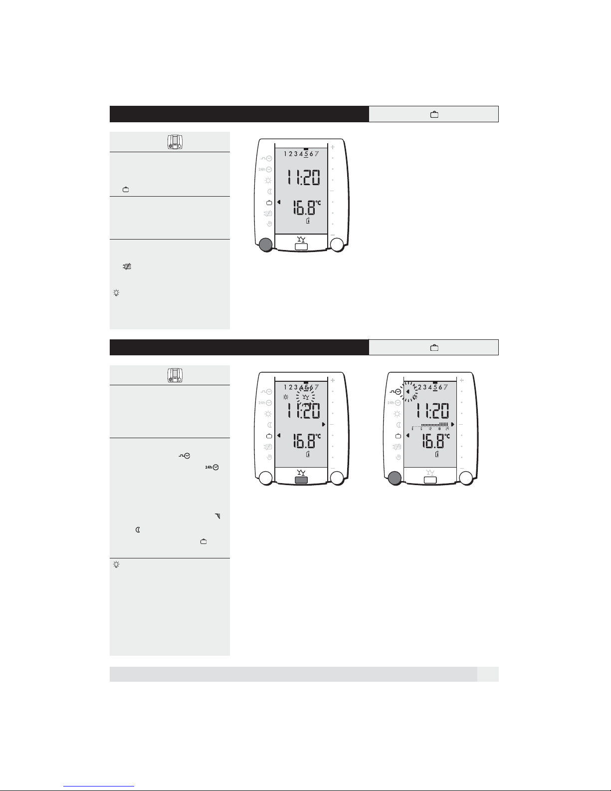
1.4 Activation of the holiday programme
Cover closed
The holiday programme can be activated in two ways:
1. Select the operating mode "Holiday"
using the left rotary knob.
2. Select the automatic holiday
programme, see "2.8 Setting the
automatic holiday programme", page
17.
Active operating modes
• Heating/warm-water heating OFF
• (Frost/room protection active)
The room protection temperature
which is valid for the holiday
programme, is set under coded
settings 3:10.
1.5 Temporary interruption of the holiday programme
Cover closed
The holiday programme can be
interrupted in two ways:
1. Activate party function, see "1.3
Party function/operating lock",
page 6.
2. Select the operating mode Weekly
clock programme or Clock
programme exception day .
At the next change to reduced heating within the automatic holiday programme, the controller returns
automatically to this setting.
If the operating mode Heating
and , is selected, it must be
changed manually back to .
A blinking symbol indicates that
another function has been selected
temporarily.
The function of the blinking symbol/
arrow is currently active.
7
Page 8
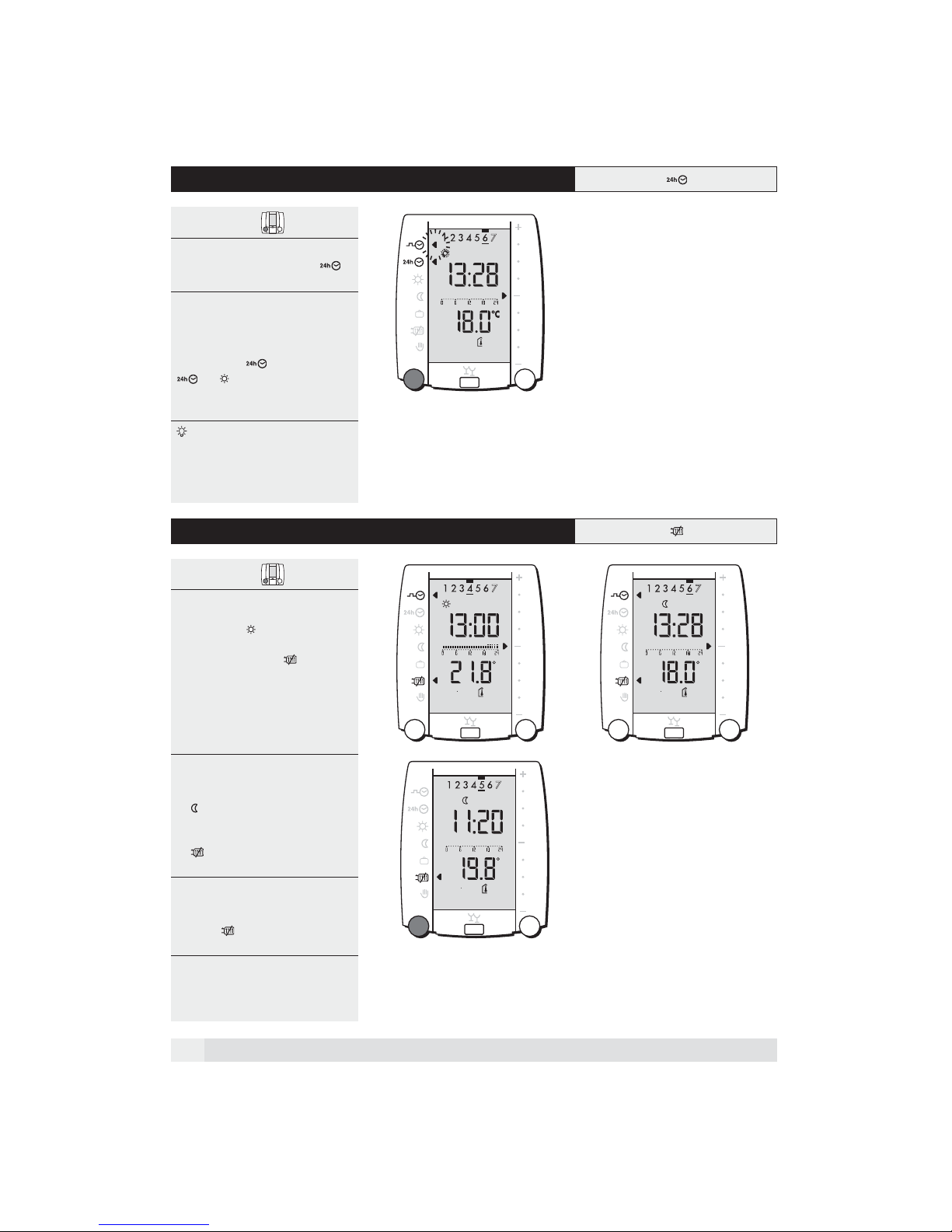
1.6 Activate the clock programme exception day
Cover closed 1
1. Select the operating mode Clock
programme exception day
with the left rotary knob.
If the Clock programme exception day
is set before 17.00 hrs, it is valid for the
whole day. If it is set after 17.00 hrs, it
becomes active on the following day, the
arrow stays on
or . The operating mode
Clock programme exception day is
reset at the next change of date.
Warm-water heating is always active parallel to heating in the selected
operating mode and starts earlier by
the set time period (setting 5:67;
factory setting, 60 mins.).
and blinks on
1.7 Heating limit
Cover closed 12
1. As soon as the outside temperature
is higher than the set Heating limit
for heating (Setting 3:04), the
controller switches to Heating OFF/
Summer operation .
The pump runs delayed to the value
in the setting 7:03.
When the temperature drops 2 K
below the Heating limit for heating,
heating operation is switched on
again.
2. As soon as the outside temperature
has climbed above the value set for
Heating limit reduced operation
(setting 3:05), the controller switches to reduced operation mode
Heating OFF/Summer operation
. Further functions are as descri-
bed above.
3. Switch off heating:
Using the left rotary knob, select the
function Heating OFF/Summer ope-
ration .
3
C C
C
8
Page 9
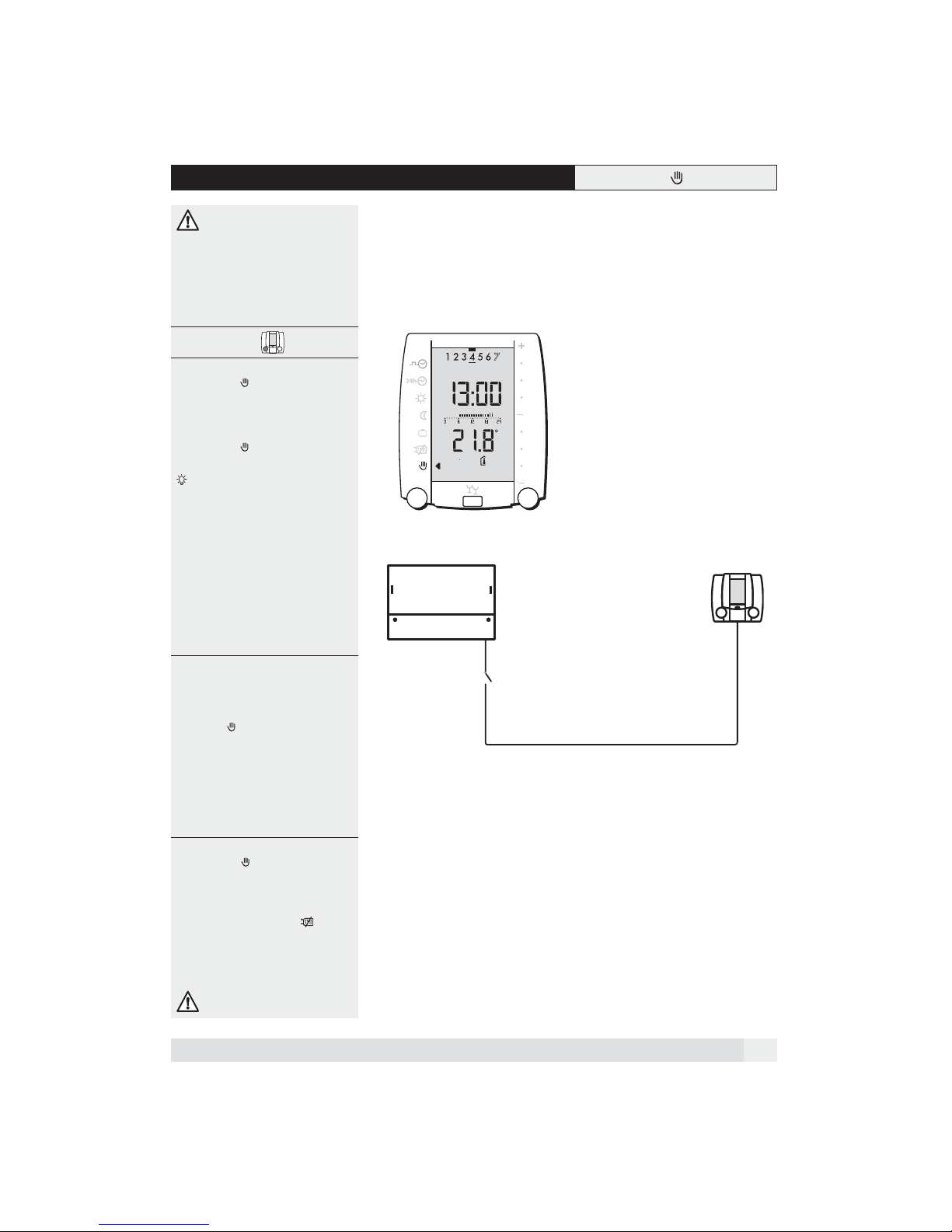
1.8 Manual / emergency operation
The temperature of the boiler
thermostat must be checked before
the operating mode Manual /
emergency operation is selected!
With floor heating, the boiler thermostat temperature must not be higher
than max. 50 °C.
Cover closed 1
The operating mode Manual/emergen-
cy operation can be selected in two
ways:
1. Using the left rotary knob, select the
operating mode Manual/emergency
operation .
The clock time, day of the week
and the room temperature display will
be updated. Other data remains
unchanged.
C
2. Interruption of the connection
between the SR 5811and the
VS 5511.
This can be done with a switch. In this
way, the SR 5811 is disconnected from
the electricity supply.
Communication between the SR 5811
and the VS 5511 plus is interrupted.
After around 60 secs., the VS 5511 plus
starts to function in Manual/emergency
operation .
• The heat generator temperature is
controlled by the boiler thermostat.
• The heating circuit pump is continu-
ally active.
• The warm-water heating function is
continually active.
• The mixer can be operated manually.
The operating mode Manual/emergen-
cy operation can fulfil two tasks:
1. During start-up by a qualified expert,
functioning of the boiler function can
be checked.
(Heating limit exceeded ).
2. In an emergency, it allows the user a
limited heating operation with warm-
water supply. .
In an emergency, call in
a qualified expert.
2
VS 5511
SR 5811
Manual
emergency operation
OpenTherm
BUS
9
Page 10

2 Operation with the cover open
Open the cover
Left rotary knob
The links to functions shown on the
display can be selected.
Right rotary knob
The right rotary knob has two functions:
1. Selection of functions shown on the
right of the display.
2. Changing the set values after selec-
tion using the push-button.
Push-button
The push-button has two functions:
1. Change settings.
2. Temporary deactivation of room
influence.
RESET
The electricity supply to the controller is
interrupted for a short time so that the
data can be reloaded.
CLEAR
By pushing the CLEAR button, the settings and the clock programme can be
reset back to the factory settings.
(See chapter 2.5, page 14 and Chapter
3.1, page 18.)
Left rotary knob
Button
Right rotary knob
All settings are valid for both
heating circuits, mixed and direct
at the same time!
10
RESET CLEAR
Functions on the left-hand side:
Date and time
Query data
Weekly clock programme
Clock programme exception day
normal, comfort, reduced
Holiday programme
Service level (further settings)
Functions on the right-hand side:
Date
Time
Start of holiday programme
End of holiday programme
Room controlled heating
Room & weather-controlled heating
Weather-controlled heating
Page 11
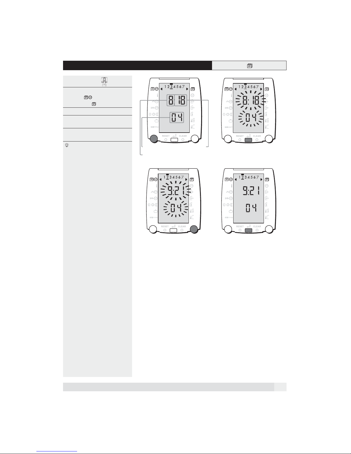
2.1 Setting the date
Open the cover 12
1. Using the left rotary knob, select the
function . The right-hand arrow
is already at .
2. Push the button, the date blinks.
3. The date can now be set by turning
the right rotary knob.
4. The new date must be confirmed by
pushing the button.
Rapid turning of the knob makes
the setting go faster!
Year
Month
Day
34
11
Page 12
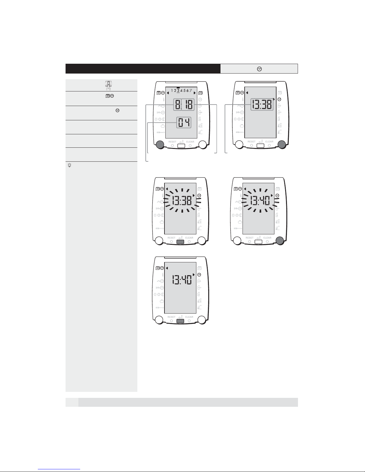
2.2 Setting the clock time
Open the cover 12
1. Select the function with the left
rotary knob.
2. Select the function Time with the
right rotary knob.
3. Press the push-button, the time dis-
play blinks.
4. The time can now be set using the
right rotary knob.
5. Confirm the new time with the push-
button.
Rapid turning of the knob makes
the setting go faster!
Year
Month
Day
34
Daytime
12
5
Page 13
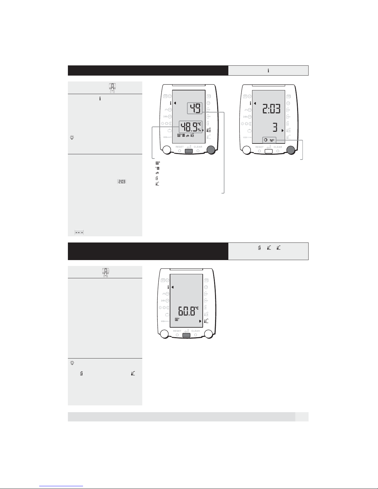
2.3 Check temperatures and operating mode
Open the cover 12
1. The function is selected.
• Select the required temperature with
the right rotary knob.
• The corresponding set value can be
shown on the upper line by pressing
the push-button.
The value for outside temperature
shown in the display remains
unchanged.
Checking the heating circuit
operating mode:
2. Continue to turn the left rotary knob.
• The current operating mode for the
heating circuit is shown
The following operating modes can be
shown :
0 = OFF 4 = Comfort
1 = Frost protection 5 = Pre-heating
2 = Reduced heating 7 = Manual
3 = Heating
2.
Measured temperatures:
=Generator temperature
=Flow temperature
=Domestic hot water temperature
=Ambient temperature
=Outside temperature
1.
The inquiry of the operating mode refers
to the current heating circuit
Setpoint value
Invalid measuring values are shown
as !
2.4 Temporarily deactivation of room temperature
influence
Cover open
1. Switch off room temperature
influence:
Hold the push-button pressed for five
seconds until the arrow jumps to the
lowest symbol.
2. Switch on room temperature
influence:
Hold the push-button pressed again
for five seconds until the right-hand
arrow has returned to the originally
selected function or ...
• at the next change to reduced hea-
ting, the arrow jumps automatically
back to the original function.
If the room temperature has been
reached and the function Room influence or Room compensation is
selected, it may be too cold in the
other rooms. In this situation, the
room temperature influence can be
temporarily deactivated.
13
Page 14
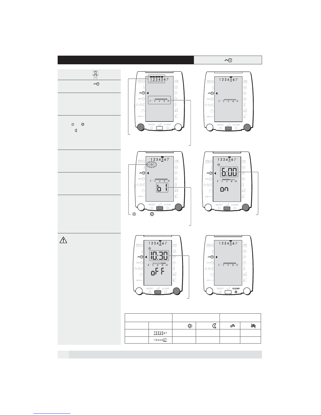
2.5 Setting the weekly clock programme
Open the cover 12
1. Select the function with the left
rotary knob.
2. Select the required day/time period
with the right rotary knob.
• Confirm the day selected with the
push-button.
3. Select the required heating tempera-
ture or with the right rotary
knob. ( does not appear)
• Confirm the selected heating tempe-
rature with the push-button.
4. Set the starting time for the time
period b1 with the right rotary knob.
• Confirm this setting with the push-
button.
5. Set the finishing time for the time
period b1 with the right rotary knob.
• Confirm this setting with the push-
button.
Points 3 to 5 must be repeated for the
time periods b2 and b3.
Unused time periods should be set to the
same start and finishing time and confirmed using the push-button.
Programme other days or daily periods
as per points 2 to 5.
The programme is only saved
(memorised) after all time periods b1,
b2, b3 have been set and confirmed
with the push-button.
The newly programmed time bars are
then shown.
2.
Day bloc with 5 days
(1=Monday, 2=Tuesday etc.)
Time program period, see page 3
34
2.
=normal, =comfort
b1, b2 or b3 are referring to the time
1.
program period
2.
Start heating period
56
1.
1.
"blinks"
Resetting of factory values for the
weekly clock programme
6. Using a fine point, press the CLEAR
button until the time bars on the
display jump back to the factory
settings.
14
2.
Stop heating period
1.
"blinks"
Factory settings for the weekly clock programme:
Daily periods Room heating Warm-water supply
Week day Display
normal
reduced
Mo-Fr 06.00 22.00 05.00 22.00
Sa-Su 07.00 23.00 06.00 23.00
On
Off
Page 15
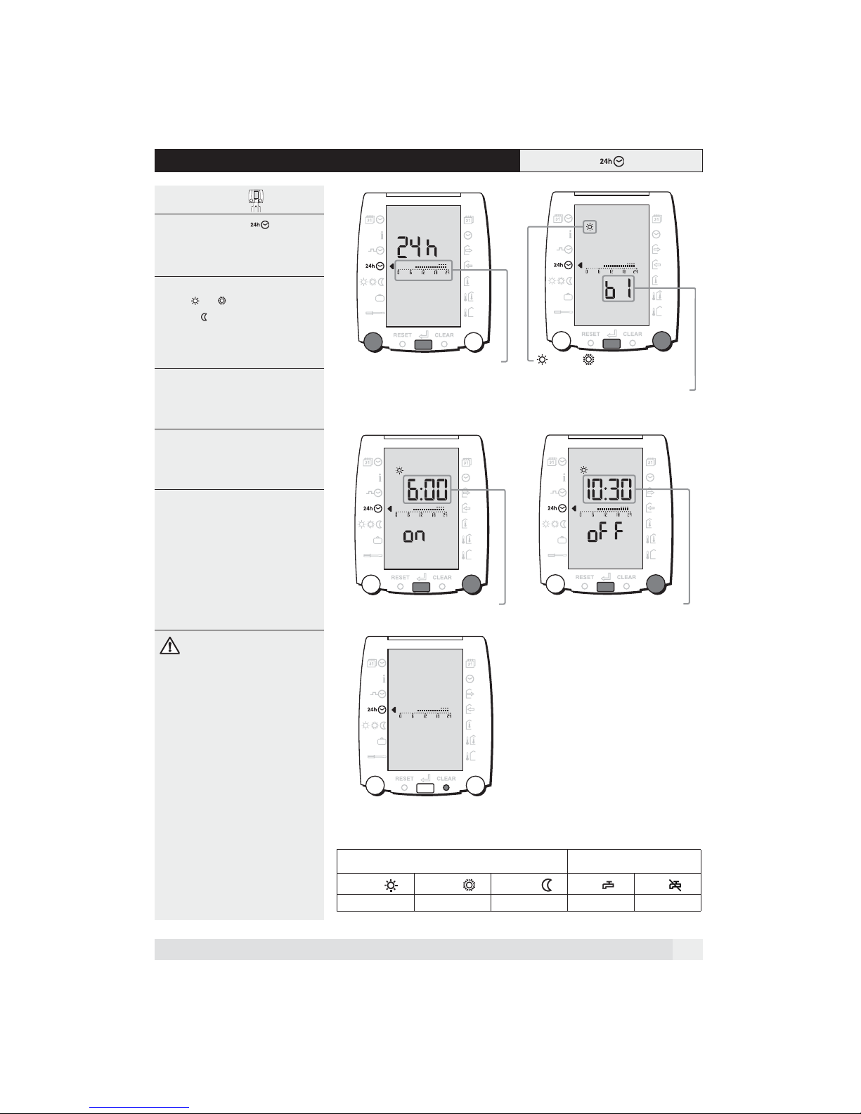
2.6 Setting the clock programme exception day
Open the cover 12
1. Select the function using the
left rotary knob.
• Confirm the selection with the push-
button.
2. Select the required heating tempera-
ture or using the right rotary
knob. ( is not shown).
• Confirm the heating temperature set-
ting with the push-button.
3. Select the starting time for the time
period b1 using the right rotary knob.
• Confirm the setting with the push-
button.
4. Select the finishing time for the time
period b1 using the right rotary knob.
• Confirm the setting with the push-
button.
Points 2 to 4 must be repeated for the
time periods b2 and b3.
Unused time periods should be set to the
same start and finishing time and confirmed using the push-button.
1.
2.
Time program period, see page 3
=normal, =comfort
b1, b2 or b3 are referring to the time
2.
34
1.
program period
The programme is only saved
(memorised) after all time periods b1,
b2, b3 have been set and confirmed
with the push-button.
The newly programmed time bars are
then shown.
Reloading of factory values for the
clock programme exception day
5. Using a fine point, press the CLEAR
button until the time bars on the display jump back to the factory settings.
2.
Start heating period
1.
"blinks"
2.
Stop heating period
5
Factory settings for the clock programme exception day:
Room heating Warm-water supply
normal
comfort reduced
08.00-17.00 17.00-23.00 23.00-08.00 07.00 23.00
On
1.
"blinks"
Off
15
Page 16
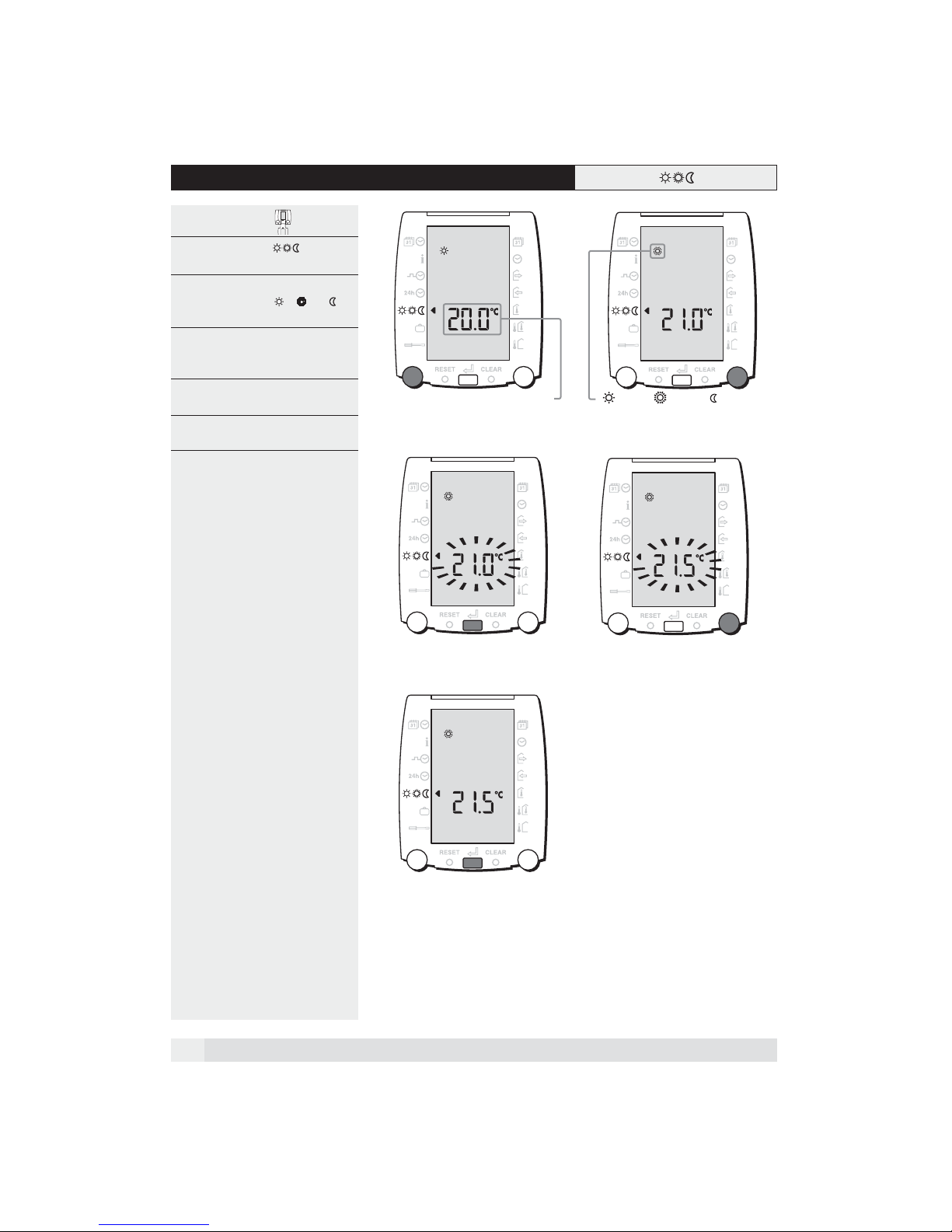
2.7 Setting the room temperature
Open the cover 12
1. Select the function with the left
rotary knob.
2. Using the right rotary knob, select the
room temperature , or to
be changed.
3. Activate the setting with the push-
button. The temperature display
blinks.
4. Set the required room temperature
using the right rotary knob.
5. Confirm this setting with the push-
button.
34
Room temperature
=normal, =comfort, =reduced
16
5
Page 17
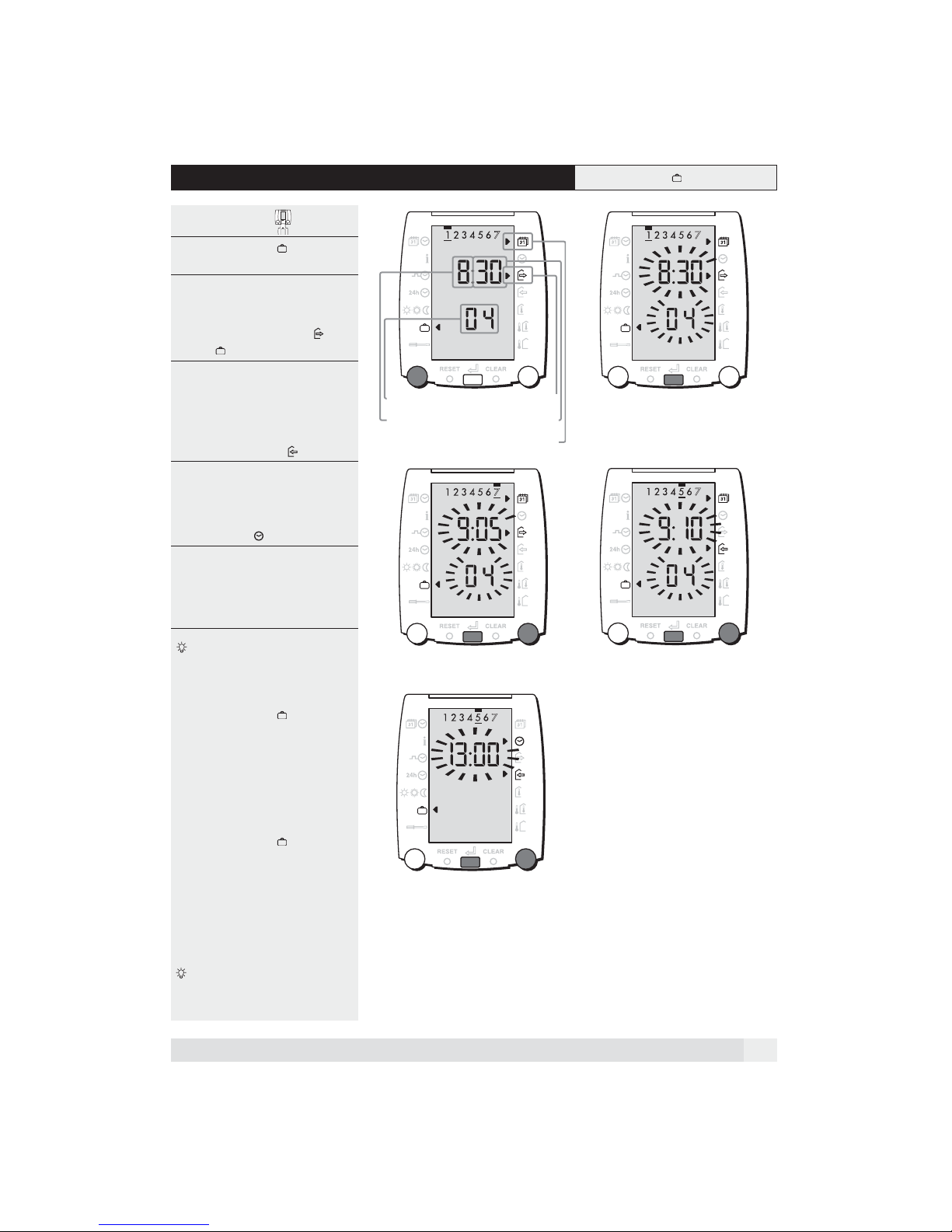
2.8 Setting the automatic holiday programme
Open the cover 12
1. Select the function using the left
rotary knob.
2. Press the push button, the datum
blinks.
• The arrows indicate the functions
Start holiday programme and
Date .
3. Using the right rotary knob, enter the
date for the start of the holiday
period.
• Confirm this with the push-button.
The arrow jumps to the function End
holiday programme .
4. Enter the date for the end of the holi-
day period using the right rotary
knob. Confirm the setting with the
push-button. The arrow jumps to the
function Time .
5. Using the right rotary knob, enter the
time for the end of the holiday period.
• Confirm the setting with the push-
button. The holiday programme is
saved.
To interrupt the holiday programme,
see "1.5 Temporary interruption of the
holiday programme", page 7.
Check the holiday programme:
1. Select the function .
2. Using the right rotary knob,
• start of the holiday period,
• end of the holiday period and
• the time for the end of the holiday
period, can be checked.
Year
Month
If " - - -" appears, no vacation program is
active
Start
Day
Date
34
2.
1.
2.
1.
5
Delete the holiday programme:
1. Select the function .
2. Press the push-button twice to arrive
at point 4.
3. Turn the right rotary knob to the left
until - - - is shown in the display.
4. Confirm this by pressing the push-
button. The holiday programme has
been deleted.
The room protection temperature
which is valid for the holiday
programme can be set in the coded
setting 3:10.
2.
1.
17
Page 18
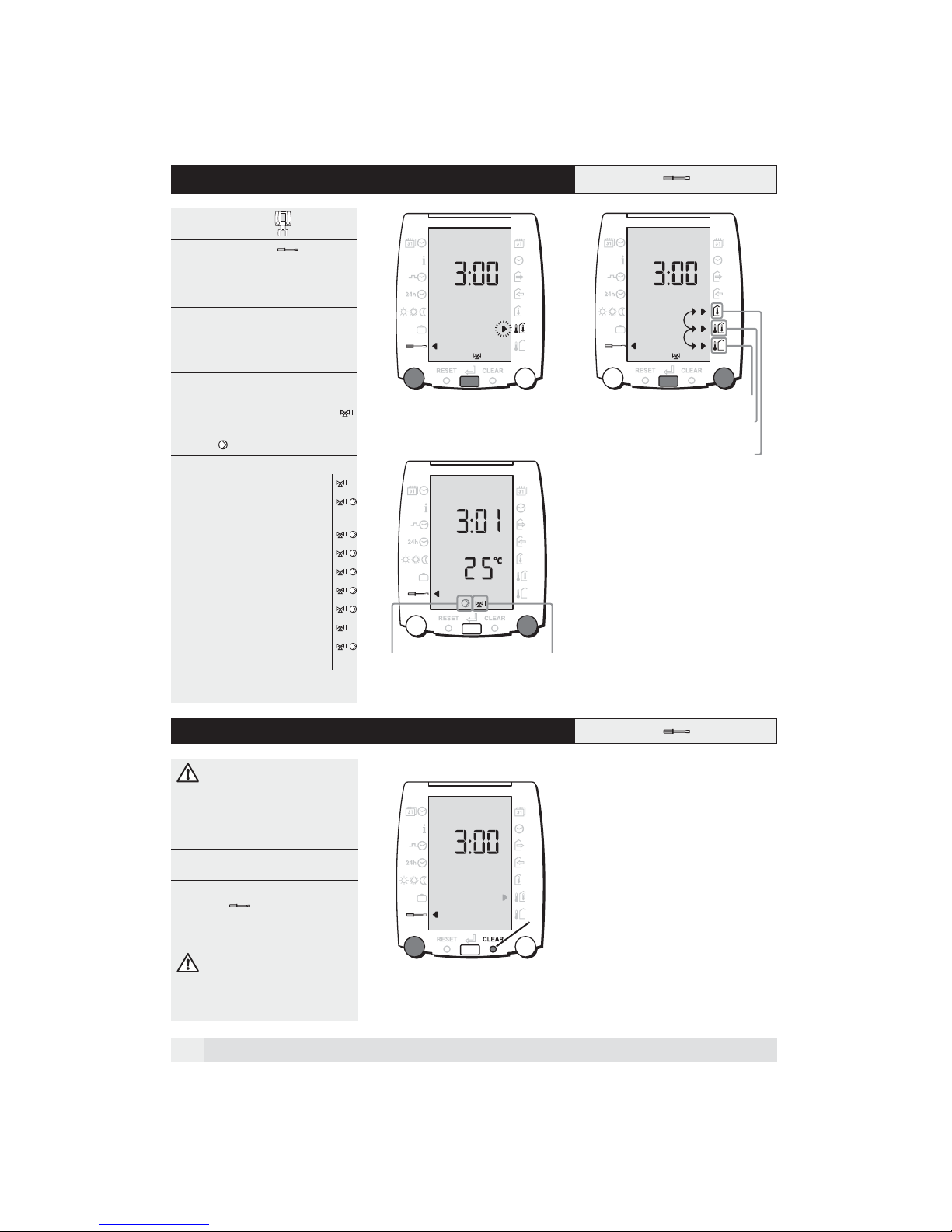
3 Settings in the service level
Open the cover 12
1. Select the function using the
left rotary knob.
• Press the push-button, the arrow to
the right in the display blinks.
2. Set the required control strategy
using the right rotary knob.
• Confirm the setting with the push-but-
ton.
3. Using the right rotary knob, all further
settings can be selected in series,
first from the mixed heating circuit
and then those from the direct heating
circuit .
The following settings are shown: HK 3
3:00 = Control strategy
3:01 = Flow temperature at an out-
side temperature of 20 °C
3:02 = Steepness of heating curve
3:03 = Max. flow temperature
3:04 = Heating limit when heating
3:05 = Heating limit when reduced
3:06 = Pre-heating time (optimised)
3:07 = Room temp. influence
3:08 = Heating limit as per flow
temperature set value
5:02 =
Warm-water temp. set value
5:67
Warm-water pre-heating time.
1.
2.
gemischter Heizkreisdirekter Heizkreis
2.
outside temperature leading
outside temperature leading with
room temperature compensation
room temperatur leading
1.
3.1 CLEAR function (reload factory settings)
WARNING:
Unintentional use of the CLEAR button deletes plant-specific settings
which can lead to malfunctioning of
the system.
Open the cover
1. Using the left rotary knob, select the
function .
2. Press the CLEAR button with a fine
point.
1.
2
When the CLEAR button is
pushed, all coded and uncoded
settings are simultaneously reset to
the factory settings.
18
Page 19
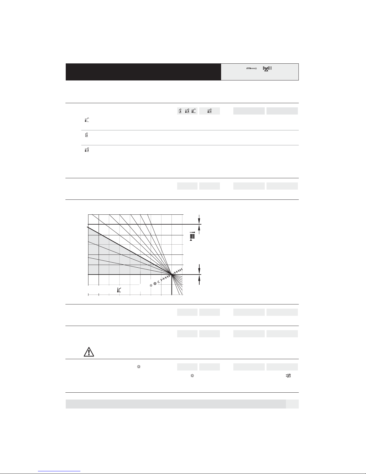
3.2 Setting level 3 - Room temperature control
mixed heating circuit
Set-
Function Setting
ting
range
Factory
setting
Unit Start-up date: Adjustment
date:
3:00 Control strategy
= Weather control only Selection criterion:
Configuration:
= Room control only Selection criterion:
Configuration:
= Weather control with room influence Selection criterion:
Configuration:
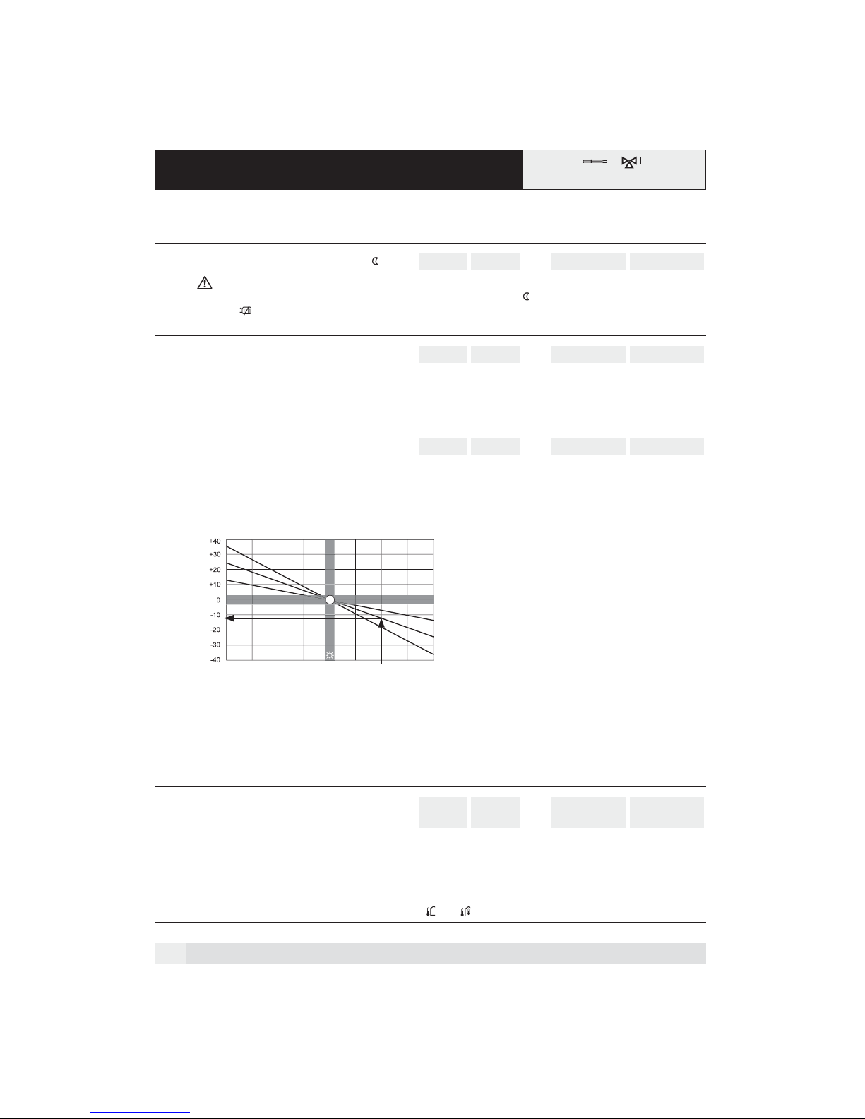
3:01 Flow temperature at outside temperature of 20°C
10÷80 25 °C
The set value for flow temperature at an outside temperature of 20°C is set here (base point).
The heating curve
1.6
1.2
0.8
0.4
0
Outside temperature
-15 -10
-20
3:02
2.4
2.0
-5
4.0 5.0
3.0
15 ˚C
ature
Roomtemper
setpoint
10
5
0
15
˚C
85
75
3: 03
65
55
45
25 ˚C
35
Flow temperature
3:01
25
15
5
20
25
˚C
-
Room temperature cannot be measured
Connect outside temperature sensor
Outside temperature cannot be measured
Install room sensor in reference room
Measurement of outside/room temperature
possible; external heat influences such as
sun, open fire place, etc.
Install room sensor in reference room
Connect outside temperature sensor
3:02 Steepness of heating curve
The heating curve shows the relationship between the heating flow and the outside temperature.
3:03 Maximum flow temperature
The flow temperature should not be higher than the set value.
This is not a safety function! When safety functions are required, e.g. with floor heating, an additional flow
safety thermostat to control the pump switch must also be installed.
3:04 Heating limit during heating
If the outside temperature exceeds the set value for heating, , the heating circuit switches to summer operation .
The pump runs at a reduced rate according to the value set in 7:03. When the temperature drops to 2K below the set value,
heating is started again.
0.0÷5.0 1.2 -
30÷90 75 °C
0÷40 20 °C
19
Page 20
3.2 Setting level 3 - Room temperature control
p
mixed heating circuit
Set-
Function Setting
ting
range
Factory
setting
Unit Start-up date: Adjustment
date:
3:05 Heating limit during reduced operation
-10÷20 10 °C
Only in the clock programme!
If the outside temperature exceeds the set value for reduced heating operation , the heating circuit switches to summer
operation . The pump runs at a reduced rate according to the value set in 7:03. When the temperature drops to 2 K below
the set value, reduced heating operation is started again.
3:06 Preheating time (optimisation)
0÷990 0 min
This ensures that the room temperature has nearly reached the set value already at the start of the heating period.
The set value (in minutes) indicates the time difference between start of preheating and start of the heating period.
The set value is accepted 100% at temperatures of -10 °C and below; at temperatures of + 20 °C and above, to 0 %.
Recommended setting: Floor heating 240; radiator heating 180.
3:07 Room temperature influence
0÷20 4 K/K
If the measured room temperature deviates from the set value, (e.g. due to other heat sources such as sunshine), the controller corrects the flow temperature by a corresponding value. The set value indicates the number of Kelvin flow temperature
correction with a room temperature deviation of 1 K.
Higher room temperature = reduced flow temperature
Lower room temperature = increased flow temperature.
Flow temperature setpoint
Flow temperature correction (K)
-4 +4
-3 -2 -1 +1 +2 + 3
Room temperature deviation (K)
Example:
Increase room temperature = 2 K; set value = 6
Decrease of the flow tem
Room temp.- Setpoint
0
erature = 12 K
0
3
6
9
Set value
0 = no compensation
1-3 = weak
Recommended setting: Do not set above 4 for floor heating!
Heating limit according to the flow temperature
3:08
set value
Summer operation becomes active when the difference between the calculated flow temperature and the room temperature
is lower then the set value.
The pump is reduced by the value given at setting 7:03.
If the difference increases to 2 K above the switch-off value, heating is started again.
-10 = OFF
2 = function active (recommended for control strategies and )
20
4-6 = medium
7-10 = strong
-10÷10 -10 K
11-20 = very
strong
Page 21
3.3 Setting level 3 - Room temperature control
direct heating circuit
Set-
Function Setting
ting
range
Factory
setting
Unit Start-up date: Adjustment
date:
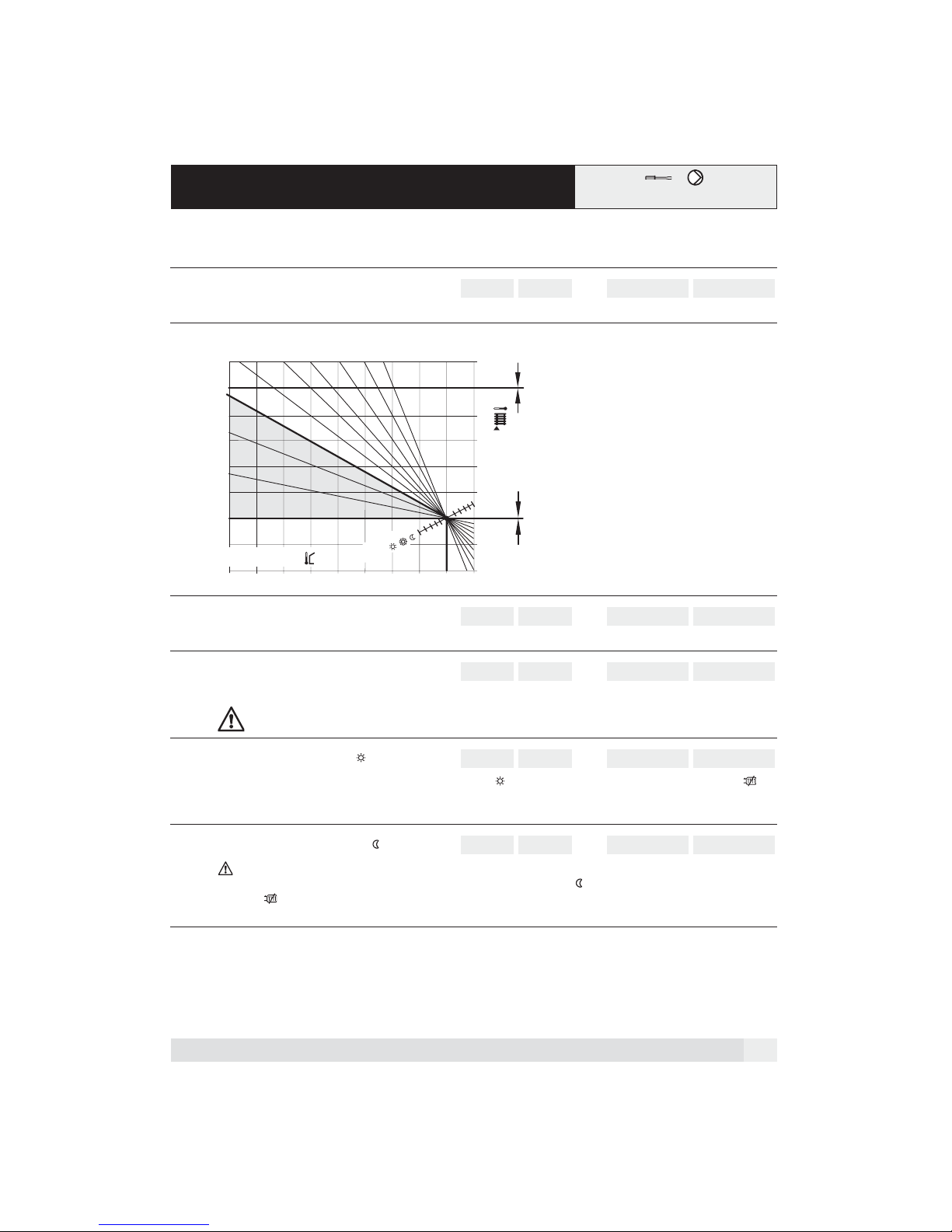
3:01 Flow temperature at outside temperature of 20 °C
10÷80 25 °C
The set value for flow temperature at an outside temperature of 20°C is set here. (base point).
The heating curve
˚C
85
75
3: 03
65
55
45
25 ˚C
35
Flow temperature
3:01
25
15
5
20
25
˚C
0.0÷5.0 1.2 -
3:02
2.4
2.0
3.0
-5
1.6
1.2
0.8
0.4
0
Outside temperature
-15 -10
-20
3:02 Steepness of heating curve
0
4.0 5.0
Roomtemperature
setpoint
10
5
15 ˚C
15
The heating curve shows the relationship between the heating flow and the outside temperature.
3:03 Maximum flow temperature
30÷90 75 °C
The flow temperature should not be higher than the set value.
This is not a safety function! When safety functions are required, e.g. with floor heating, an additional flow
safety thermostat to control the pump switch must also be installed.
3:04 Heating limit during heating
0÷40 20 °C
If the outside temperature exceeds the set value for heating, , the heating circuit switches to summer operation .
The pump runs at a reduced rate according to the value set in 7:03. When the temperature drops to 2K below the set value,
heating is started again.
3:05 Heating limit reduced operation
-10÷20 10 °C
Only in the clock programme!
If the outside temperature exceeds the set value for reduced heating operation , the heating circuit switches to summer
operation . The pump runs at a reduced rate according to the set value 7:03. When the temperature drops to 2 K below
the set value, reduced heating operation is started again.
21
Page 22
3.3 Setting level 3 - Room temperature control
direct heating circuit
Set-
Function Setting
ting
range
Factory
settings
Unit Start-up date: Adjustment
date:
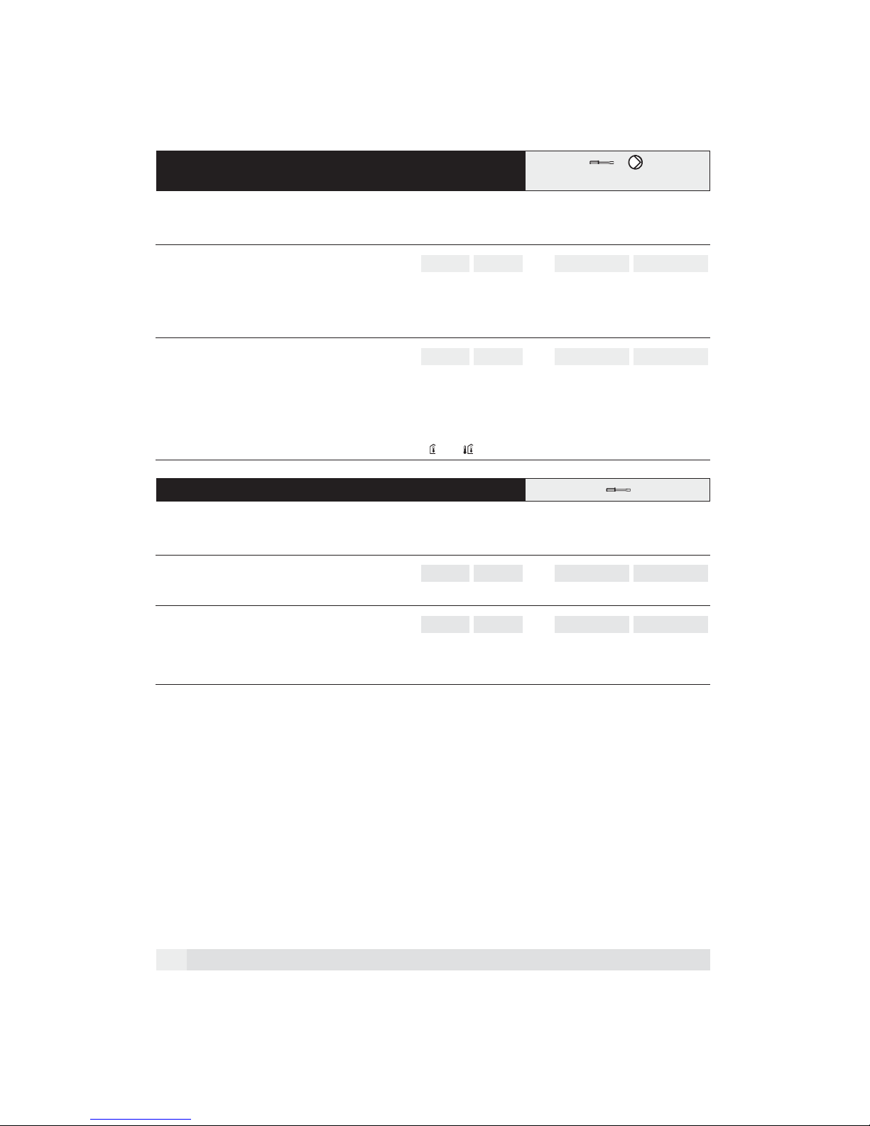
3:06 Pre-heating time (optimisation)
This ensures that the room temperature has nearly reached the set value already at the start of the heating period.
The set value (in minutes) indicates the time difference between start of preheating and start of the heating period.
The set value is accepted 100% at temperatures of -10 °C and below; at temperatures of + 20 °C and above, to 0 %.
Recommended setting: Floor heating 240; radiator heating 180.
3:08 Heating limit as per flow temperature set value
Summer operation becomes active when the difference between the calculated flow temperature and the room temperature
is lower then the set value.
The pump is reduced by the value given at setting 7:03.
If the difference increases to 2 K above the switch-off value, heating is started again.
-10 = OFF
2 = function active (recommended for control strategies and ).
0÷990 0 min
-10÷10 -10 K
3.4 Setting level 5 - Domestic hot water supply
Set-
Function Setting
ting
5:02 Domestic hot water temperature set value
This setting is used to select the set value for domestic hot water temperature.
5:67 Domestic hot water pre-heating time
Heating of the warm-water supply is always active parallel to heating operations in the selected clock programme and is started earlier by the value (time) set here.
200 = Heating of domestic hot water supply is continually active in the clock programme.
range
10÷70 55 °C
0÷200 60 min
Factory
setting
Unit Start-up date: Adjustment
date:
22
Page 23
4 Settings in the coded service level
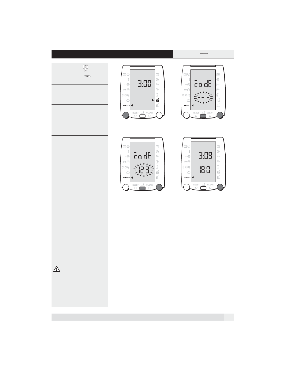
Open the cover 12
1. Select the function with the
left rotary knob.
2. Turn the right rotary knob until
"Code" appears.
3. Press the push-button, the code
entry blincks on the display.
4. Enter the code using the right rotary
knob.
• Confirm the selection with the push-
button.
5. Turn the right rotary knob to the right,
the coded settings appear.
The following settings appear:
3:09 =
Duration party function
3:10 =
Room protection temperature
3:30 =
Room temperature controller
adjustment time
Room temperature controller
3:31 =
hold-back time
Room temperature actual value
3:81 =
correction
Follow-up time, warm-water
5:03 =
supply
Legionella protection temp.
5:04 =
Day selection legionella
5:05 =
protection
Warm-water supply parallel or
5:07 =
with priority over heating
Minimum heat generation
6:00 =
temperature
Maximum heat generation
6:04 =
temperature
Switching difference heat
6:05 =
generator.
Proportional mixer range
7:00 =
Follow-up time circulation pump
7:03 =
Running time mixing valve
7:13 =
2.
34
2.
1.
1.
The code can be obtained from
your heating expert.
23
Page 24
4.1 Setting level 3 - Room temperature control
Set-
Function Setting
ting
range
Factory
setting
Unit Start-up date: Adjustment
date:
3:09 Duration party function
0÷250 180 min
This setting is used to define the duration of the party function .
3:10 Room protection temperature
-10÷20 10 °C
This setting is used to define the room protection temperature valid for the holiday programme and for summer operation
. Values smaller than + 2 °C should only be set in agreement with qualified experts!
3:30 Room temperature controller hold-back time
0÷150 30 min
This function prevents a lasting deviation of actual room temperature from the set value. The smaller the hold-back time, the
quicker is the change in flow temperature with a control deviation.
If the set value is too small, there is a danger of vibration. 0 = no function
Recommended settings: Floor heating = 60; radiator heating = 30
3:31 Room temperature controller adjustment time
0÷30 3 min
This serves to improve control stability with an anticipation time. The adjustment time allows an anticipation of possible future
control deviations and starts a proportional adjustment to the expected deviation and allows a future deviation to be corrected
at an early stage.
Recommended settings: Floor heating = 6; radiator heating = 3
3:81 Room temperature actual value correction
-5.0÷5.0 0K
This setting allows the measured room temperature shown in the display, to be changed e.g. for adjustment to measured
values of another temperature measuring device.
4.2 Setting level 5 - Domestic hot water supply
Set-
Function Setting
ting
range
Factory
setting
Unit Start-up date: Adjustment
date:
5:03 Follow-up time domestic hot water supply
0÷15 3 min
The domestic hot water charge function is active after the end of the domestic hot water heating for the time period set.
5:04 Legionella protection temperature
60÷80 60 K
This setting gives the set value for legionella protection (thermal disinfection).
5:05 Day selection legionella protection
0÷8 0-
The domestic hot water is heated once for two hours after the first demand for domestic hot water on the chosen day, to the
temperature set as legionella protection temperature. (Legionella protection temperature as per setting 5:04).
0 = no function
1 = Monday
2 = Tuesday
Domestic hot water supply parallel or with priority
5:07
over heating
1 = Priority with charging pump
3 = Wednesday
4 = Thursday
5 = Friday
1÷3 1-
3 = Priority operation with diverter valve
6 = Saturday
7 = Sunday
8 = daily
2 = Parallel operation with charging pump
24
Page 25
4.3 Setting level 6 - Heat generator (Boiler)
Set-
Function Setting
ting
range
Factory
setting
Unit Start-up date: Adjustment
date:
6:00 Minimum heat generation temperature
The set value which the heat generator maintains during operation.
6:04 Maximum heat generation temperature
The set value which should not be exceeded by the heat generator.
6:05 Switching difference heat generator
The actual heat generator temperature set value plus this set value gives the switch-off temperature set value for the heat
generator.
0÷60 0°C
50÷90 90 °C
2÷30 6K
4.4 Setting level 7 - Heating circuit
Set-
Function Setting
ting
7:00 Proportional mixer range
The P-range dictates via which set/actual value deviation the "OPEN" and "CLOSE" commands are continually given (not
pulsating). A small set value creates a larger change in the mixture with increasing deviation.
The mixing circuit reacts quickly. (For actuators with long running times.) A large set value creates a smaller change in mixture
with increasing deviation. The mixing circuit reacts slowly.
(For actuators with short running times.)
7:03 Follow-up time circulation pump
The heating circuit pump continues to run after the end of heating operation for the period of time set.
range
10÷60 30 K
Factory
setting
3÷30 15 min
Unit Start-up date: Adjustment
date:
7:13 Running time mixing valve
With a continually active mixing command (continually OPEN or CLOSED command), the command is deactivated after
a double running time. This function serves to protect the controller and mixer drive from damage.
0.5÷24.0 5.0 min
25
Page 26
5 Constant values
The functions and values described in the following can be neither selected or set. It is however necessary to know them, as
they have an influence on the functioning of the controller.
5.1 Domestic hot water supply
Function Factory setting Unit
Over-increase heat generator temperature for the warm-water supply
In order for domestic hot water to be heated efficiently and rapidly, a heat generator temperature increase to the domestic hot water
set temperature is given.
20 K
5.2 Heating circuit
Function Factory setting Unit
Over-increase heat generator temperature to flow temperature set value
The set value for the heat generator is higher than the required flow temperature set value by this value during heating operations.
5K
5.3 Frost protection function
Function Factory setting Unit
Frost protection function
The frost protection function is active in the chosen operating mode Heating OFF.
If the outside temperature drops below + 2 °C, the heating circulation pump becomes activated for 6 minutes each hour.
If the outside temperature rises above + 4 °C, the frost protection function is inactive.
If the flow temperature drops below 10 °C, the heating circulation pump is immediately activated for 6 minutes.
If the flow temperature remains below 10° C after 6 minutes, a heating charge request with a flow temperature set value of 15 °C is
activated.
+ 2 °C
26
Page 27
6 General points
6.1 What makes up the VS 5500 plus?
The VS 5500 plus is made up of:
• An operating unit SR 5811
• A controller VS 5511 plus
• An outside sensor ZAF 500
• A flow sensor ZVF 210
Optional:
• Warm-water sensor ZTF 222
• Boiler sensor ZTF 222
6.2 What does the VS 5500 plus control?
The VS 5500 plus controls:
• 1 weather-controlled mixed heating
circuit
• 1 weather-controlled direct heating
circuit
• 1 warm-water supply
• 1 heat generator with a one-stage
burner
Operation is carried out only via the
SR 5811
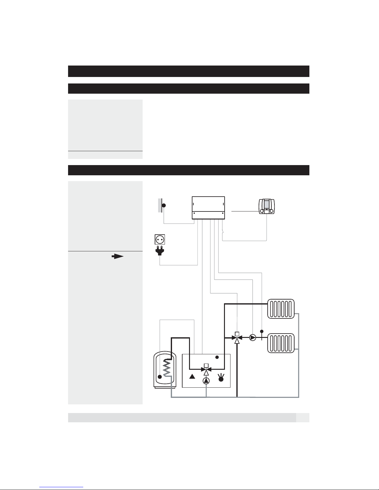
6.3 Hydraulic
Application alternatives:
1. Without heat generator
• Do not attach the boiler sensor
2. Without warm-water supply
• Do not attach the warm-water sensor
3. Direct heating circuit (without mixer)
• Do not attach the flow sensor
• Set the setting 3:01 lower by 5 K.
Outside temperature sensor
VS 5511 plus SR 5811
Room temperature
sensor inside
Manual/
emergency mode
OpenTherm
BUS
DHW sensor
Burner
Boiler sensor
M
M
Mixing
valve
Flow sensor
Pump
27
Page 28
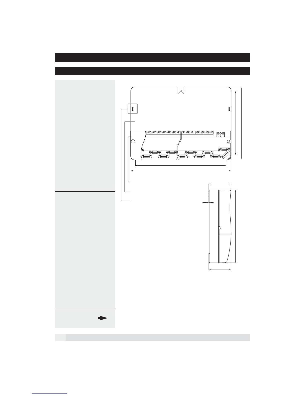
7 Dimensions and installation
7.1 Installation VS 5511 plus
Determination of position
The VS 5511 plus control unit should be
placed as close as possible to the heat
generator/heating circuit so that only a
short cable is required.
Mounting the base plate
The base plate of the VS 5511 plus
control unit is fastened to the wall using
three screws.
1. Drill the top, middle hole and screw in
the screw.
2. Hang in the unit without the clamp
cover and mark the lower two screw
holes.
3. Remove the unit and drill the two
lower holes.
4. Replace the unit again and fasten the
lower screws.
The controller can now be connected
to the electricity supply.
Terminal cover
B
127.5
145
5
6
10 9 8
11
12
4
7
6
5
3
1
2
180.5
200
3
1
7
2
NNN
4
L
B
44.3
Installation notes
• The electrical installation and protection must be carried out and must
confirm to local regulations.
• The VS 5511 plus must have a continual electricity supply in order to
ensure functioning at all times.
• Peripheral switches must be limited
to emergency or main switches
which are usually continually
switched on.
• Before start-up, it should be checked
that all components are connected
correctly to the electricity supply.
• If strong inductive forces exist in the
vicinity of the controller (protectors,
magnet valves etc.), interference
suppression using RC links directly
to the coil connectors of the interfe
ring components may be necessary.
Recommended RC-links: 0.047 PF,
100 : . for 250 VAC (e.g. Bosch,
RIFA, etc...).
7.2 Dimensions
VS 5511 plus
Controller housing
Attachment hook controller housing
B = Screw anchorage at the wall
2
145
44.8
-
28
Page 29
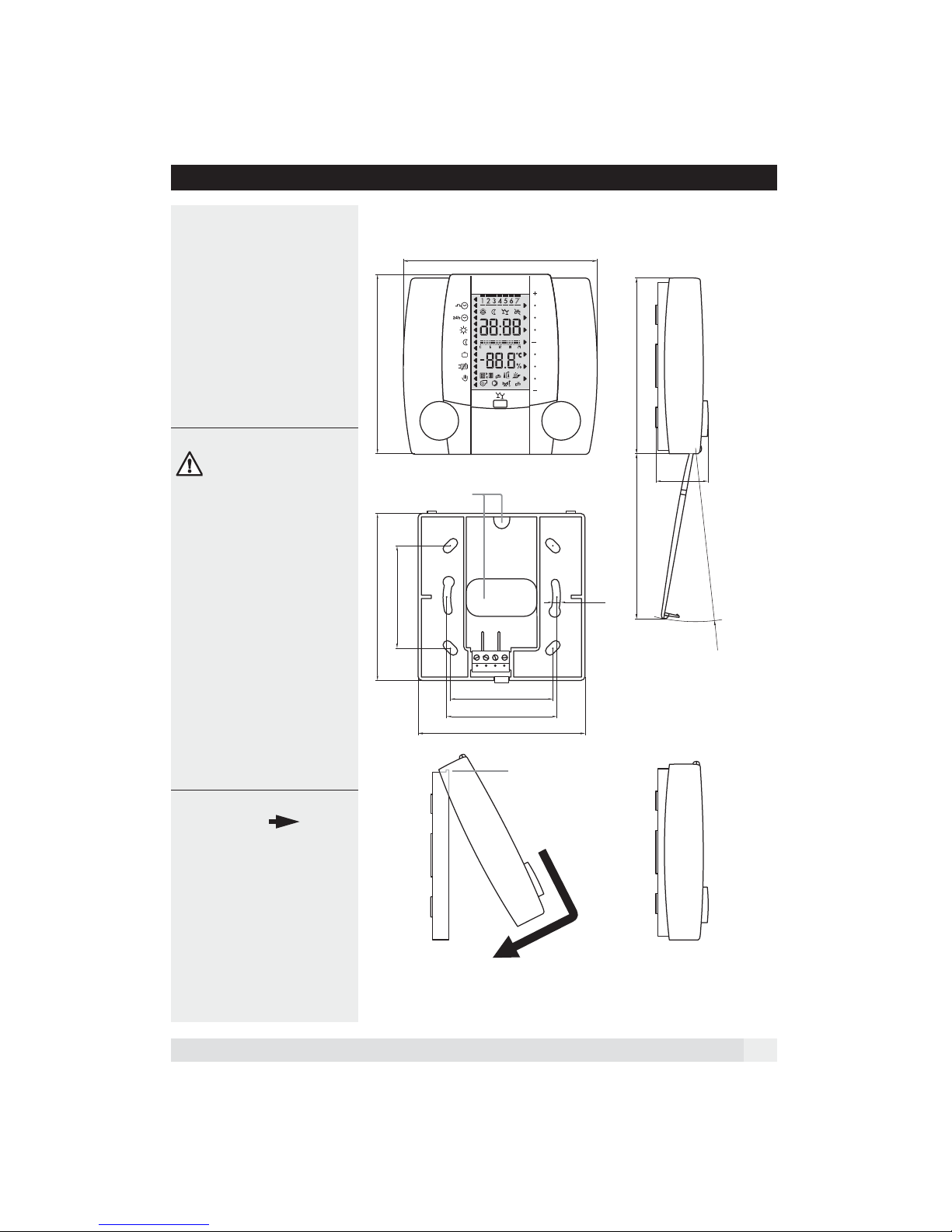
7.3 Installation SR 5811
Determination of position
If the SR 5811 is used to record the room
temperature, the following positioning
actors should be taken into consideration:
• In the reference room on an inside
wall with normally heated next room.
No other controllers, e.g. thermostat
valves, must be active in this room.
• Approx. 150 cm above floor level.
• Ensure free air circulation (not in
niches or cupboards etc.)
• Not directly next to a heat source or
exposed to direct sunlight.
Cable connection of the SR 5811
Front view Side view
106
98
open
Make sure that all cables are
disconnected from the electricity
supply before you begin work on the
wiring. The controller must be disconnected before installing or removed the operating unit. Never touch
the wires, printed back or connections of the operating unit.
Connecting cables should be fed
through the cable ducts provided (avoid
coiling and twisting of cables).
Junction lines to the VS 5511 must be installed separately to the high voltage power lines.
7.4 Dimensions
SR 5811
91.3
Wiring opening
56
Assembly base
Wiring room
1 4
56
60.4
91.3
Cam
30.4
90.4 96
4.2
R95
Siede view
closed
Mounting on the assembly base
29
Page 30
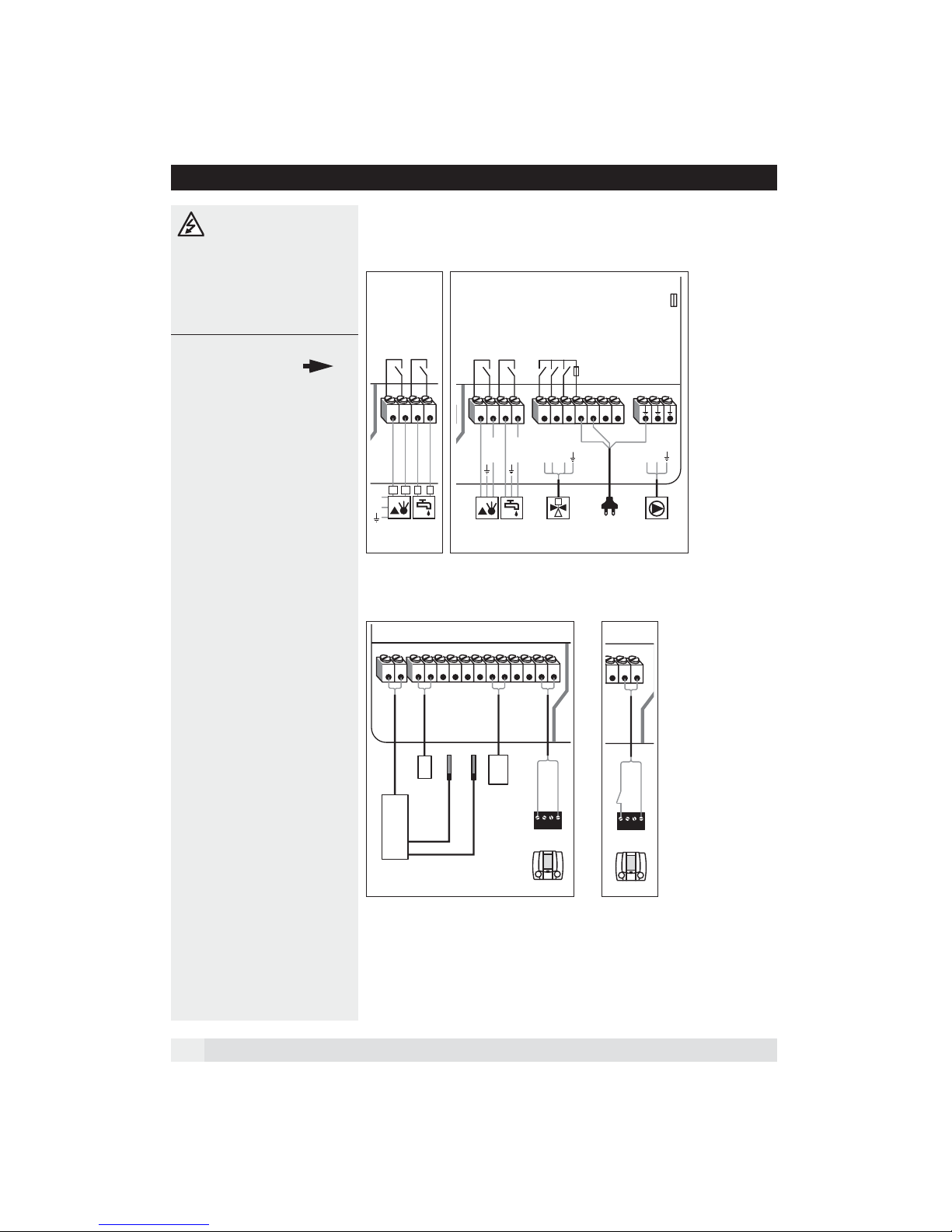
7.5 Start-up
The mains current connections to the right no. 1-7/LN are ’live’
with 230 Volt. These clips may only be
touched if they are not connected to
the electricity supply, otherwise there
is a danger of fatal electric shock.
7.6 Electrical installa-
tion diagram
When starting up, check that:
• the controller is switched on!
• the clock programme is correctly
programmed!
• the temperature values are set
correctly!
• heating is sensible given the outside
temperature!
• fuel is available!
• the fuel line is open!
• clock time and date are set properly!
• the switch manual/emergency opera-
tion is switched on!
Controller test
In order to test the controller and the
appertaining equipment, the following
queries can be made via the SR 5811
after the heat generator has been
switched on:
1. Open the cover
2. Press the RESET button (bottom left
next to the party button)
The SR 5811 will now be initialised. The
following can be seen on the display:
1. The software number (e.g. 510 000)
2. This is followed by the software ver-
sion (e.g. SW 0.1)
3. All segments of the display will then
be shown.
If the controller then returns to the normal display, the internal function test
was successful.
Mains current connection functional units (230 VAC):
DHW
a
T
Flowtemp.
Switching contact
4567
b
T
1112
sensor
Alternative 2
Boiler
T
DHW sensor
Boiler sensor
Close
Open
Mixer
DHW
Switching contact
Switching contact
45
67
L
L
N
N
Pump
3.15 A
321LNNN
32
N
M
230 V~
1N
Option hand switch:
T
T
Outsidetemp.
sensor
T
12345678910
1 4
Connecting
terminals
SR 5811
T
T
123
mode
Switch
Manual
1 4
Connecting
terminals
SR 5811
T
Alternative 1
Boiler
Switching contact
T1
T2
L
N
Connection sensors:
T
3231
Boiler
Opentherm
Firing controller
Opentherm
30
Page 31
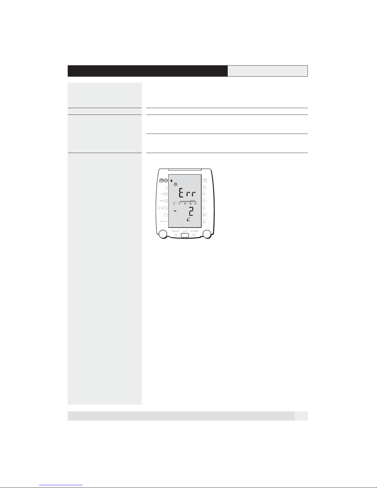
8 Help in solving problems
If no basic display or an error message
are shown after switching on, the explanations in the following table may be of
help.
Problem Possible cause Remedy
No display Controller not switched on
External switch is set to manual/emergency
operation
SR 5811 deactivate Push the RESET button
Error display Communication to VS 5511plus is
interrupted
Check the fuses, switch the controller on.
Change the switch for manual/emergency
operation.
If necessary, carry out a plausibility test
with a second controller.
Check connecting cable. Has the controller
been installed properly?
31
Page 32
9 Technical data
9.1 Technical data SR 5811
Supply voltage via Bus cable
Ambient operating temperature 0 °C ... 50 °C
Bus interface: OpenTherm 2-cable bus, twisted,
Bus cable, length, cross-section max. 50 m, min. 0,5 mm
Certification
Protection class III EN 60730
Protection when installed correctly IP 40 EN 60529
EMV EN 50082-1
Supply voltage via bus cable
Ambient operating temperature 0 °C ... 50 °C
Running reserve 24 h (after 3 operating days)
9.2 Technical data VS 5511 plus
Supply voltage 230 VAC ±10 %, 50-60 Hz
Performance take-up 2 VA
Sensor circuit voltage 12 V, insulation strength 4 KV
Ambient temperature 0 °C ... 55 °C
Sensor cable length, cross-section
Bus interface: OpenTherm 2-cable bus, twisted,
Output switching capability
• Mech. ports: right 1-7 250 VAC, 6 (2)A, 50 Hz,
Certification
Fused
Protection class II EN 60730
Protection when installed correctly IP 40 EN 60529
EMV EN 50082-1
EMV-Emission EN 50081-1
interchangeable
The controller is conform as per the
following EU guidelines:
• 73/23/EWG "Low voltage guideline"
• 89/336/EWG "EMV guideline", including
the change guidelines up to 93/68/EWG
max. 100 m; 0,75 mm
interchangeable
ohmisch cos M => 0,95
The controller is t conform as per the
following EU guidelines:
• 73/23/EWG "Low voltage guideline"
• 89/336/EWG "EMV guideline", including
the changes guidelines up to 93/68/EWG
Fine fuse 3.15 A; 250 VAC; SPT
5 x 20 mm
2
2
32
Page 33

9.3 Sensor resistance values
Temperature °C Resistance NTC 5 k:
-20 48'535
-15 36’475
-10 27’665
-5 21’165
0 16’325
5 12’695
10 9’950
15 7’855
20 6’245
25 5’000
30 4’029
40 2’663
50 1’802
60 1’244
70 876
80 628
90 458
100 339
9.4 Explanation of terms and abbreviations
b1, b2, b3 Time periods which can be set for the clock programme.
h Hours
Actual value Temperature measured
K Kelvin, difference in temperature
min Minutes
Net Mains electrical supply 230V VAC
OpenTherm 2-cable data bus for heating technology
Set point value Temperature set by the operator or calculated by the controller, which controls the actual
value set by the heating controller.
33
Page 34

Notes:
34
Page 35

10 Index
A
Automatic holiday programme setting 17
C
Check heating circuit operating mode 13
Check temperatures and operating mode 13
CLEAR 10
CLEAR function (factory setting charge) 18
Clock programme activate exception day 8
Clock programme set exception day 15
Control strategy 19
Correction of faults 31
E
Explanation of terms and abbreviations 23
F
Frost protection function 26
H
Heating curve 19, 21
Heating limit 8
Hydraulic 27
I
Installation SR 5811 29
Installation VS 5511 eco 28
L
left rotary knob 10
Set weekly clock programme 14
Settings in the coded service level 23
Settings in the service level 18
Start-up 30
T
Technical data 32
W
Warm water heating 22
What does the VS 5500 eco control ? 27
What makes up the VS 5500 ? 27
M
Manual/emergency operation 9
P
Party function/operating lock 6
R
RESET 10
right rotary knob 10
Room temperature setting 16
Room temperature adjust temporarily 6
Room temperature influence switch off temporarily 13
Room temperature adjustment direct heating circuit 21
Room temperature adjustment mixed heating circuit 19
S
Select operating mode 5
Sensor resistance values 33
Set clock time 12
Set date11
35
Page 36

Manufacture or distribution:
 Loading...