

Page 1

TelVue
User Manual
R
AdCaster
TM
Author:
James Slocum
c
TelVue Corporation
October 17, 2013
Document Version:
0.3
Page 2

Contents
I Setting Up the AdCaster
1 Getting Started 3
1.1 What is the AdCaster? . . . . . . . . . . . . . . . . . . . . . . . . 3
1.2 A Basic Setup . . . . . . . . . . . . . . . . . . . . . . . . . . . . . 4
2 Initial Network Configuration 5
2.1 Fresh out of the box . . . . . . . . . . . . . . . . . . . . . . . . . 5
2.2 Using the front panel LCD . . . . . . . . . . . . . . . . . . . . . 6
2.3 Using the web app . . . . . . . . . . . . . . . . . . . . . . . . . . 8
II Configuring the AdCaster
3 Splicers and Ad Channels 13
3.1 Setting up splicers . . . . . . . . . . . . . . . . . . . . . . . . . . 13
3.2 Setting up channels . . . . . . . . . . . . . . . . . . . . . . . . . . 13
4 Schedules and Content 18
4.1 Importing schedules from the programming tab . . . . . . . . . . 18
4.2 Scheduling a window manually . . . . . . . . . . . . . . . . . . . 19
TM
TM
12
III Using the AdCasterTMDashboard 22
2
5 Dashboard Overview 23
5.1 A Tour of the Dashboard features . . . . . . . . . . . . . . . . . . 23
5.2 Configuring Filters . . . . . . . . . . . . . . . . . . . . . . . . . . 24
5.3 Getting Detailed Information . . . . . . . . . . . . . . . . . . . . 24
1
Page 3

Part I
Setting Up the AdCaster
TM
2
Page 4
Chapter 1
Getting Started
1.1 What is the AdCaster?
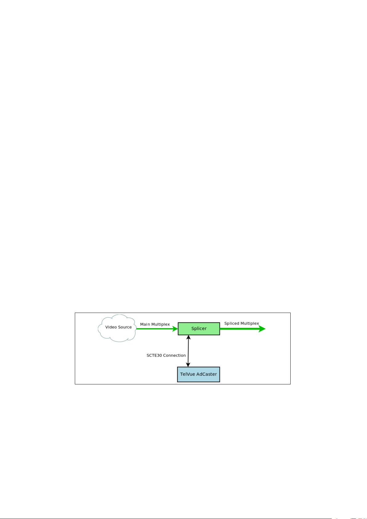
The AdCaster is a SCTE30 compliant ad server that can be connected to a
splicer to serve long and short form advertising. The AdCaster connects to the
splicer over TCP port 5168 (by default). The splicer receives a main feed which
contains SCTE35 embedded markers. These markers tell the splicer when it
is okay to replace the main feed content (usually ad spots) with local content
(figure 1.1). The splicer then communicates with the AdCaster via the TCP
connection and requests content to play over the main feed. The AdCaster then
delivers the requested content. A successful transaction between the splicer and
the AdCaster will result in a seamless replacement of the main ad with the local
ad (figure 1.2).
Figure 1.1: The AdCaster communicates with the splicer waiting for a CUE
message.
3
Page 5
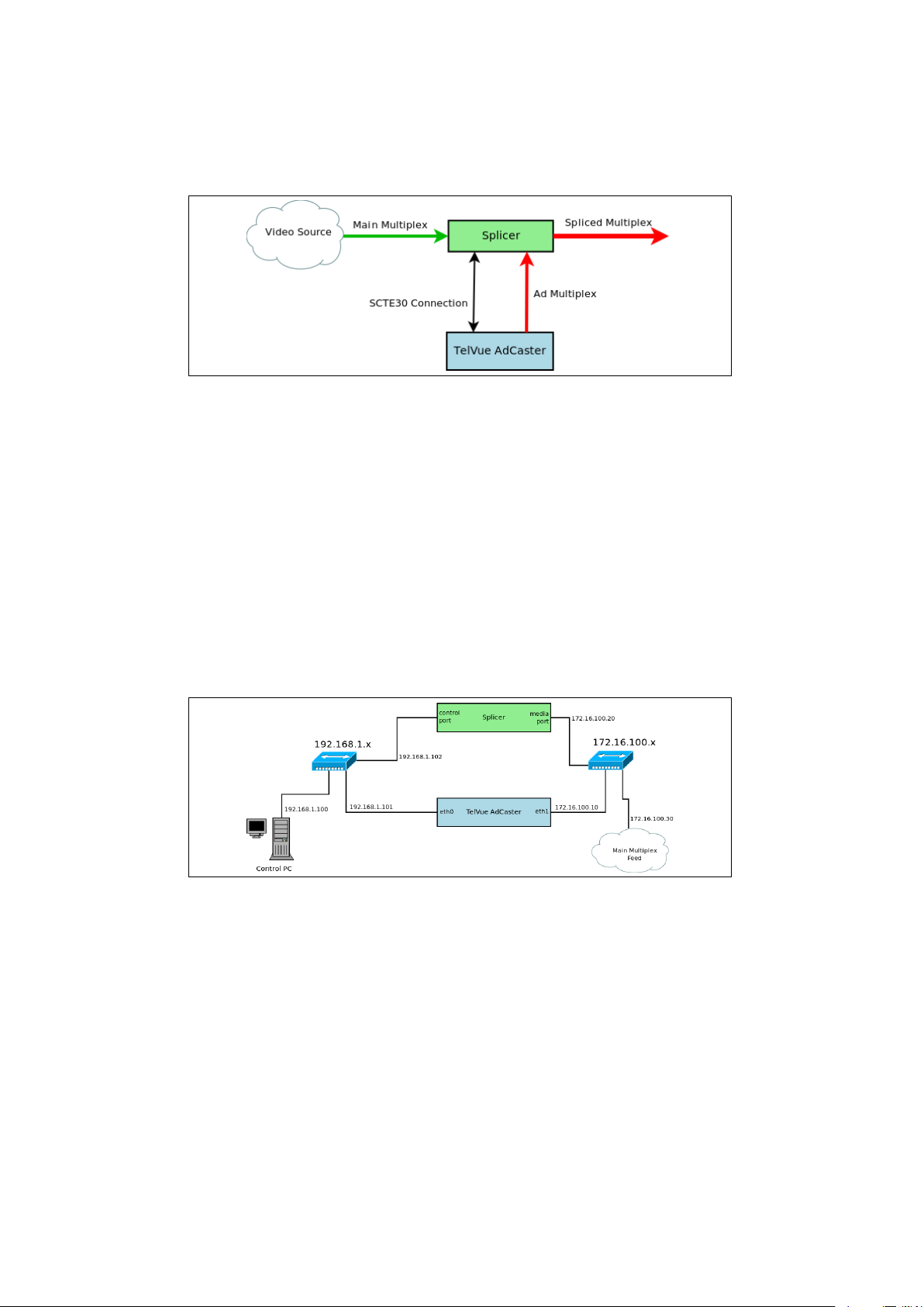
Figure 1.2: During an ad break, the AdCaster will send a replacement ad, and
the Splicer will insert it.
1.2 A Basic Setup
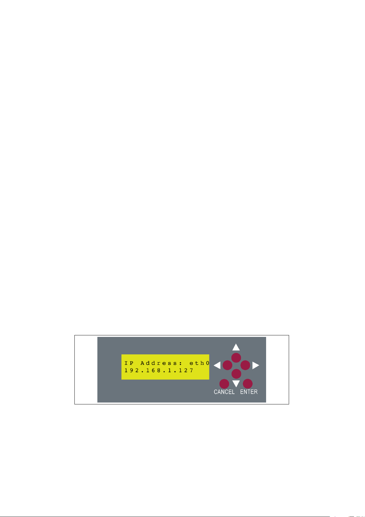
The AdCaster standard configuration has four copper Ethernet ports labeled
eth0, eth1, eth2, and eth3. An additional two copper, or two fiber ports can be
optionally outfitted, normally during factory build. eth0 is usually configured
to be the control port which will provide access to the web app. The rest are
usually configured as the media ports and should be placed on the same network
as the media port on the respective splicers. As seen in figure 1.3, the multiplex
(audio and video data) is usually isolated to a single network, and the control
another. The control network may also contain a traffic and billing server, a
storage server for centralizing media and scheduling data, and other control
interfaces for different equipment.
Figure 1.3: This is an example of how the AdCaster could be set up on a
network. Here the 192.168.1.x network is the control network allowing access to
the AdCaster web app. The 172.16.100.x network is the video network.
4
Page 6
Chapter 2
Initial Network
Configuration
2.1 Fresh out of the box
When you first receive your AdCaster. It has the eth0 set to use dynamic host
configuration protocol (DHCP), and eth1 set to the static address 10.1.0.0 with
a subnet mask of 255.255.0.0. If you have a DHCP server set up then the
AdCaster will get its own IP address and be ready to use. You can use the front
panel LCD to view the IP address it has obtained. If you don’t have a DHCP
server or want to set the AdCaster to use a static IP address instead, please
refer to the next section. Please note that if eth2 and eth3 are not connected,
they will not appear in the configuration menu of the front panel LCD.
To see the IP address obtained from DHCP, use the front panel LCD located
on the front of the AdCaster unit.
Figure 2.1: This is an example of what the IP address display looks like for
eth0.
Using the left and right arrows on the front panel LCD, you can scroll though
the displays until you see the IP address screen. See figure 2.1 to see what the
5
Page 7
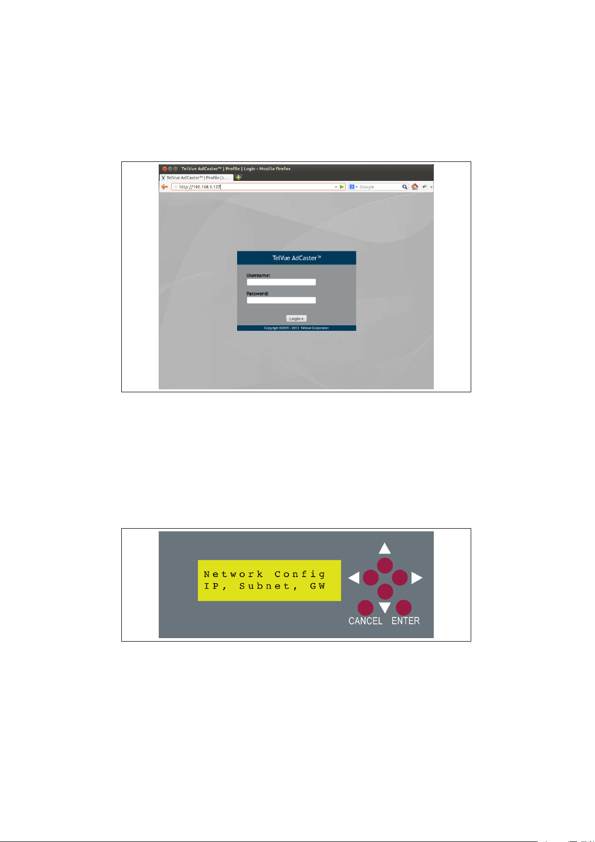
screen would look like. Once you have the IP address of the AdCaster unit you
can access the web application with a browser.
Figure 2.2: The AdCaster login page
2.2 Using the front panel LCD
If you do not have DHCP set up on the control network, you can set the IP
address using the front panel LCD. To begin configuring the network settings
on the server, navigate to the configuration menu shown in figure 2.3 using the
up or down arrow key.
Figure 2.3: The network configuration menu screen
Press enter to access the configuration sub-menu. If there are more then
one network cables attached to the system the first menu will ask which device
should be configured (figure 2.4). You will want to select eth0.
After selecting eth0 and pressing the enter key, you will be asked to select
6
Page 8
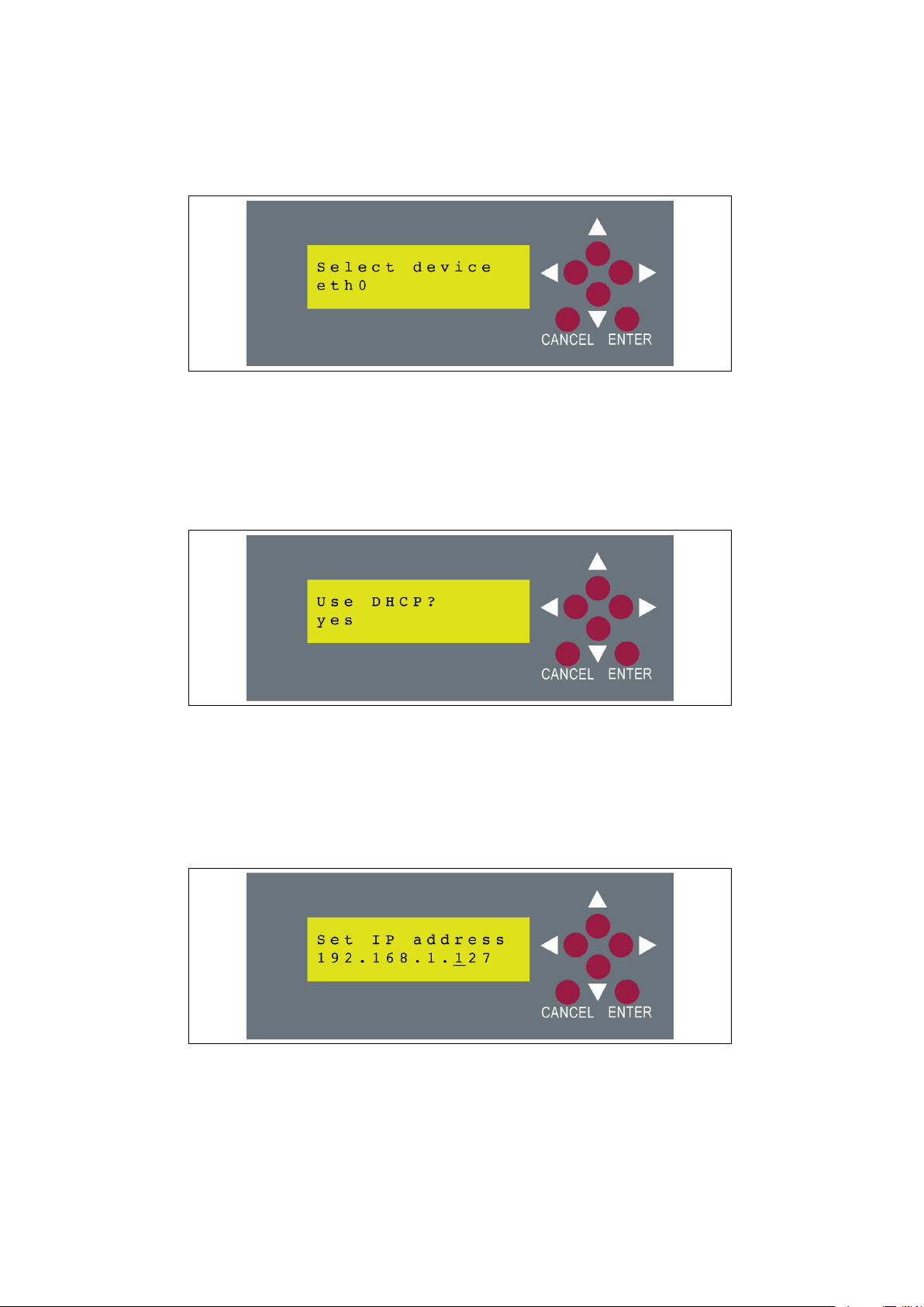
Figure 2.4: This screen allows the user to select which device they want to
configure. Use the up and down arrows to select a device.
either DHCP or static configuration. Selecting DHCP will try to auto-configure
the Ethernet device, but requires that you have a DHCP server on the network.
Using the up and down arrows you can select the no option and begin the static
IP configuration.
Figure 2.5: This allows the user to use choose between DHCP and static
configuration.
The IP address for the device must now be specified. Use the left and right
arrows to select the part of the IP to modify. Then use the up and down arrows
to adjust its value. An underscore will appear below the value that is currently
being modified. Make sure you are using a valid IP address for the network the
AdCaster is on.
Figure 2.6: Set the static IP of the unit. Use the left and right arrows to select
the digit, and the up and down arrows to modify it.
Once a valid IP address has been entered, press the enter key to accept and
7
Page 9
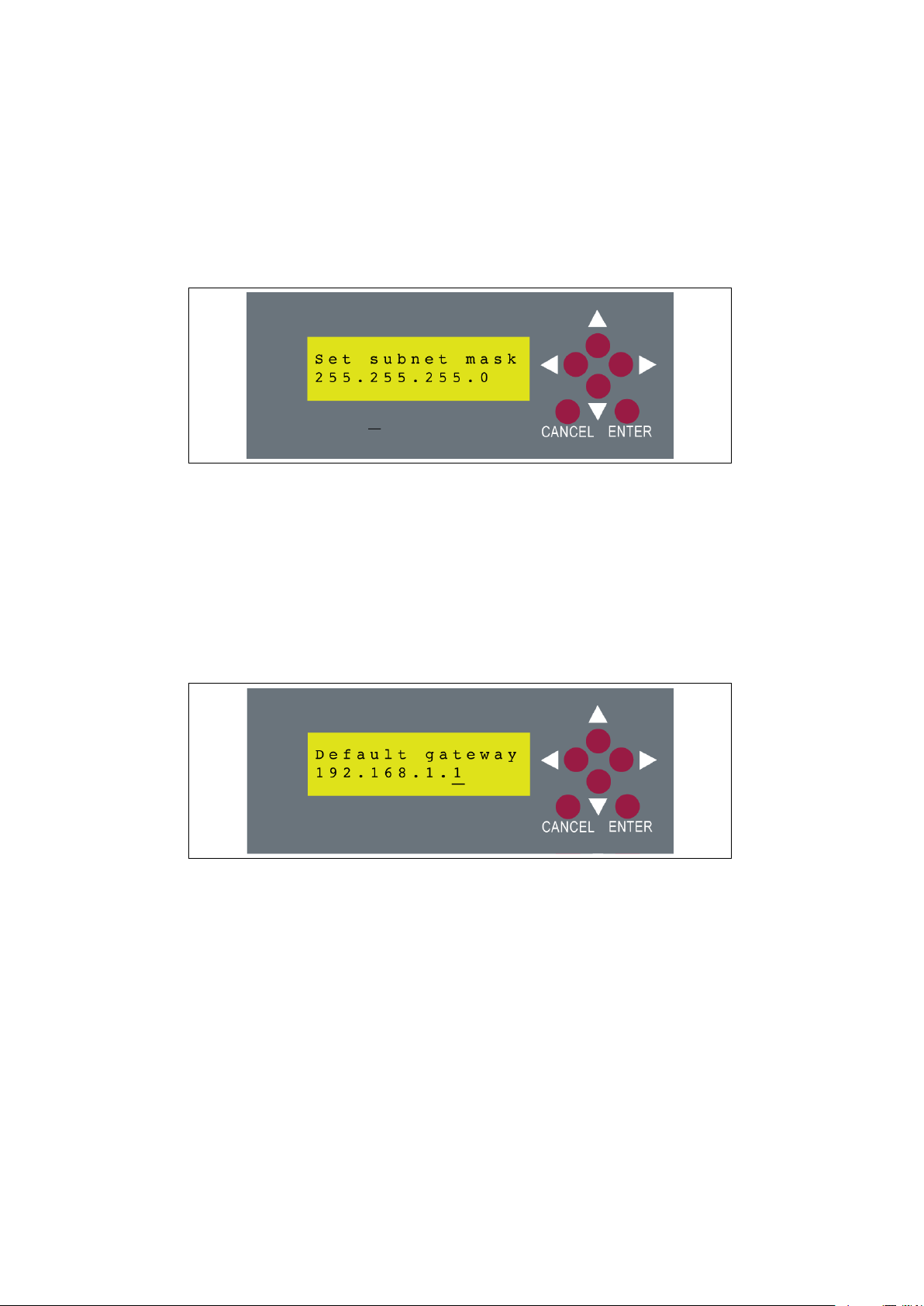
go to the next menu. On the next menu the subnet mask for the IP address
will be entered (figure 2.7). The display will pre-compute what it thinks the
subnet mask should be based on the current IP, but it may need to be adjusted
depending on the special configuration of the network it is being attached to.
Figure 2.7: Set the subnet mask.
Just like configuring the IP address, the subnet is configured in the same
way. Use the up and down arrows to change the value of the highlighted digit,
and the left and right arrows to select the digit to change. When the netmask
has been successfully entered, press the enter key to continue to the next menu.
The next menu will allow you to set the default gateway. This menu works
exactly the same as the previous two. Once you have entered the address of the
default gateway and pressed enter, the settings will take and you will be able
to access the web app.
Figure 2.8: Set the default gateway.
2.3 Using the web app
Once you have the network set up on eth0, you will be able to access the
AdCaster web application. This application is used for all tasks going forward.
When you first connect to the AdCaster you will be prompted for a user name
and password. The default login and password are given in figure 2.9.
It is recommended that you change this password especially if the AdCaster
has an Internet facing address.
8
Page 10

login psgadmin
password psgadmin
Figure 2.9: The default login and password for the AdCaster web app.
Once you have logged into the web application you will be presented with
the default dashboard. See figure 2.10 for details. Since this is a new unit it
will tell you that there are no channels configured on the system. Configuring
splicers and channels is covered in chapter 3.
Figure 2.10: The dashboard display on a new AdCaster unit. Note that no
channels have been configured yet.
To continue with the network configuration click on the “Config” tab at
the top of the screen under the date display. Once you are on the configuration
screen click on “Server”, then “Network” located on the left hand side bar. This
will bring you to the screen shown in figure 2.11.
Once you are on this screen you can make network configuration changes,
such as setting up eth1 for use on the video network. Click on the “Edit”
button below the interface table. This will take you to the edit screen shown in
figure 2.12. You can choose either DHCP or static configuration. Once you are
satisfied with the configuration press the save button to commit your changes.
After you have saved your changes, if you will be using Multicast on your
video network, click the ”Route All Multicast” link next to the edit link for
whichever eth device you have hooked to the video network (most likely your
eth1 device.) Once this step is complete you are ready to begin setting up
9
Page 11
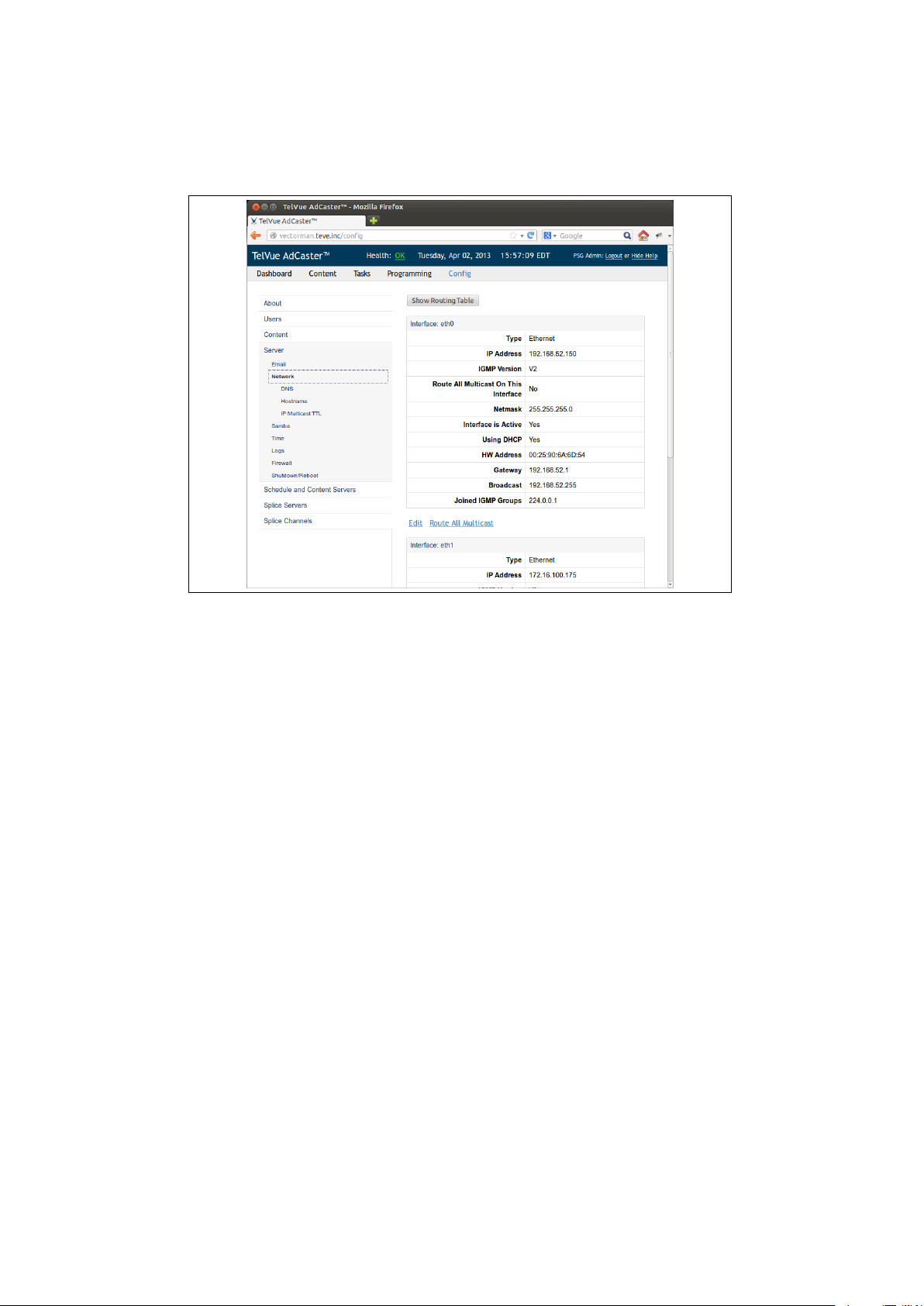
Figure 2.11: Using the web app, you can configure eth1, route multicast traffic,
and view the routing table for the AdCaster.
splicers and channels, and loading up content.
10
Page 12

Figure 2.12: The edit interface page will allow you to make changes to the
selected Ethernet card.
11
Page 13

Part II
Configuring the AdCaster
TM
12
Page 14

Chapter 3
Splicers and Ad Channels
3.1 Setting up splicers
The AdCaster can be configured to work with any number of different splicers.
Splicers are defined in the “Splice Servers” section of the “Config” tab. Figure
3.1 shows what the splicer server configuration screen looks like. Once you are
on this page you can add a splicer by pressing the plus (+) button at the bottom
of the table shown in figure 3.2.
Once you click that button you will be taken to the edit screen where you can
enter the splicer name, Management IP address, and port number for the splicer
SCTE-30 connection (figure 3.3). Remember that the “splicer name” field value
must exactly match the name parameter in the splicers configuration. You must
refer to the specific splicer’s documentation to see what this value should be.
After you have set the splicer specific parameters you must also specify where
the ad stream is going to be sent. The “Stream IP Address” can be any unicast
or multicast address. For unicast, the destination IP will generally be the IP
address of the splicer’s video network port.
After you have configured your splicer, you will see it listed in the table like
in figure 3.4. You can repeat the above steps to add as many splicers as you
want. You only need to add a single splicer once, as you can associate many
channels with a single splicer.
3.2 Setting up channels
Once you have set up all of your splicers, it is now time to ad some channels.
Since each splicer is slightly different about what configurations it can and
13
Page 15
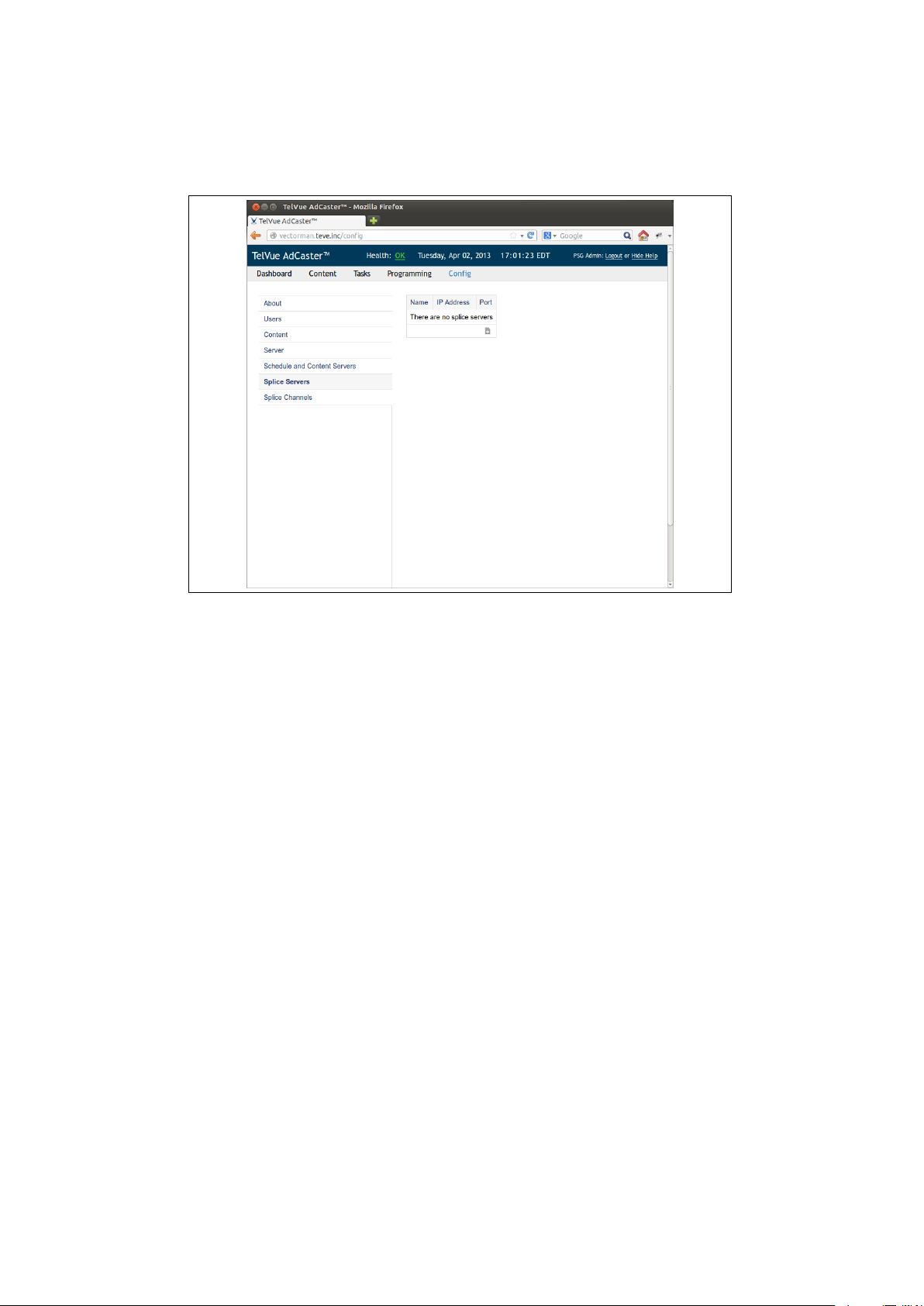
Figure 3.1: The splice server config page will allow you to add, remove, and
edit individual splice server configurations.
cannot handle we provided a large set of configuration options. If at anytime
you need a hint about what each configuration option means you can click on
the question mark (?) symbol next to the name of the configuration parameter.
To begin setting up splicer channels you will want to click on the “Config”
tab and then on the “Splice Channels” tab on the left side pane. This will
present you with another table view like in figure 3.2. Pressing the plus (+)
button will bring you to the channel configuration page like the one in figure
3.5.
It is important that you consult the manual for your splicer because the configuration for each splicer is very different. the “Name”, “Version”, “Chassis”,
“Card”, and “Port” are unique for each splicer make and model.
14
Page 16
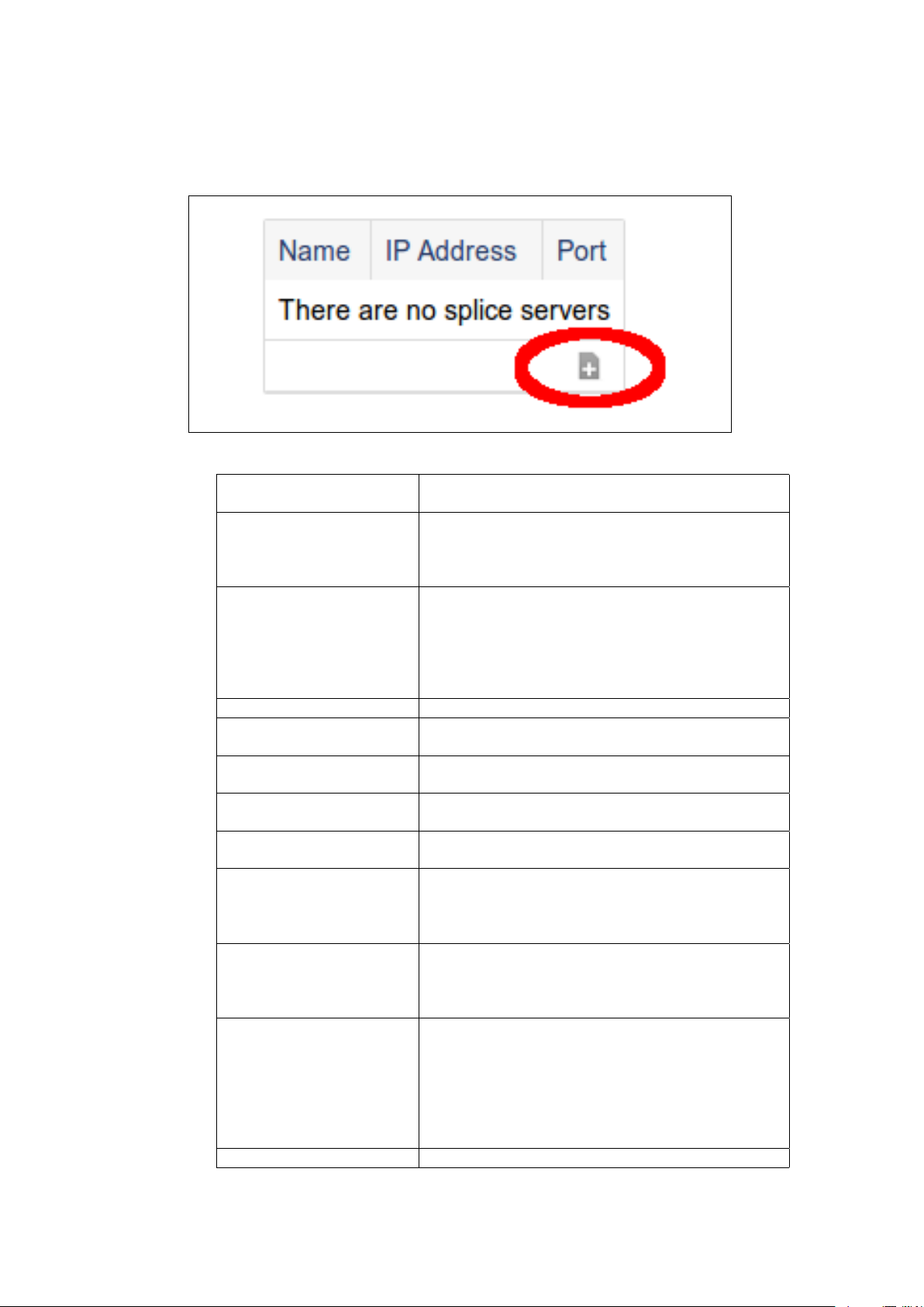
Figure 3.2: Press the plus button to add a new splicer.
Name The splice channel name. Must match the channel
name in the splice server configuration.
CCMS Network ID The network ID of this channel within the headend
location. Used to find appropriate CCMS schedule
files, which should contain valid network and headend ID’s.
CCMS Headend ID The headend ID where this channel is located. Used
to find appropriate CCMS schedule files, which
should contain valid network and headend ID’s. If
a server wide headend ID is specified, that value will
be defaulted here (but can be overridden on a chan-
nel by channel basis).
Version The scte30 protocol version used by the splice server.
Chassis This value must match the splice server ”chassis”
value. Check splice documentation for correct value.
Card This value must match the splice server ”card” value.
Check splice documentation for correct value.
Port This value must match the splice server ”port” value.
Check splice documentation for correct value.
Access Type The type of access this connection has, with 0 being
low priority and 9 being the highest priority.
Break Stop Rule Two choices are avilable. Stop on Cue - this will
cause the channel to respect all stop tones. Stop on
Media - This will cause the channel to ignore the stop
tones and play until the media has completed.
Cue Offset Use this field if you know that your SCTE35 Cue
messages are incorrect by a known constant amount.
Value is expressed in milliseconds, and can range
from -8000 to 8000.
Provider Avail ID Filtering Disable Filtering - All tones will be accepted, regard-
less of provider avail ID presense or value. Accept
tones with any ID(s) - Only tones with provider avail
ID(s) will be accepted. Only accept tones with the
following ID(s) - Only tones with provider avail ID(s)
specified and matching the specified list will be ac-
cepted.
Splice Server The channel’s associated splice server.
15
Page 17
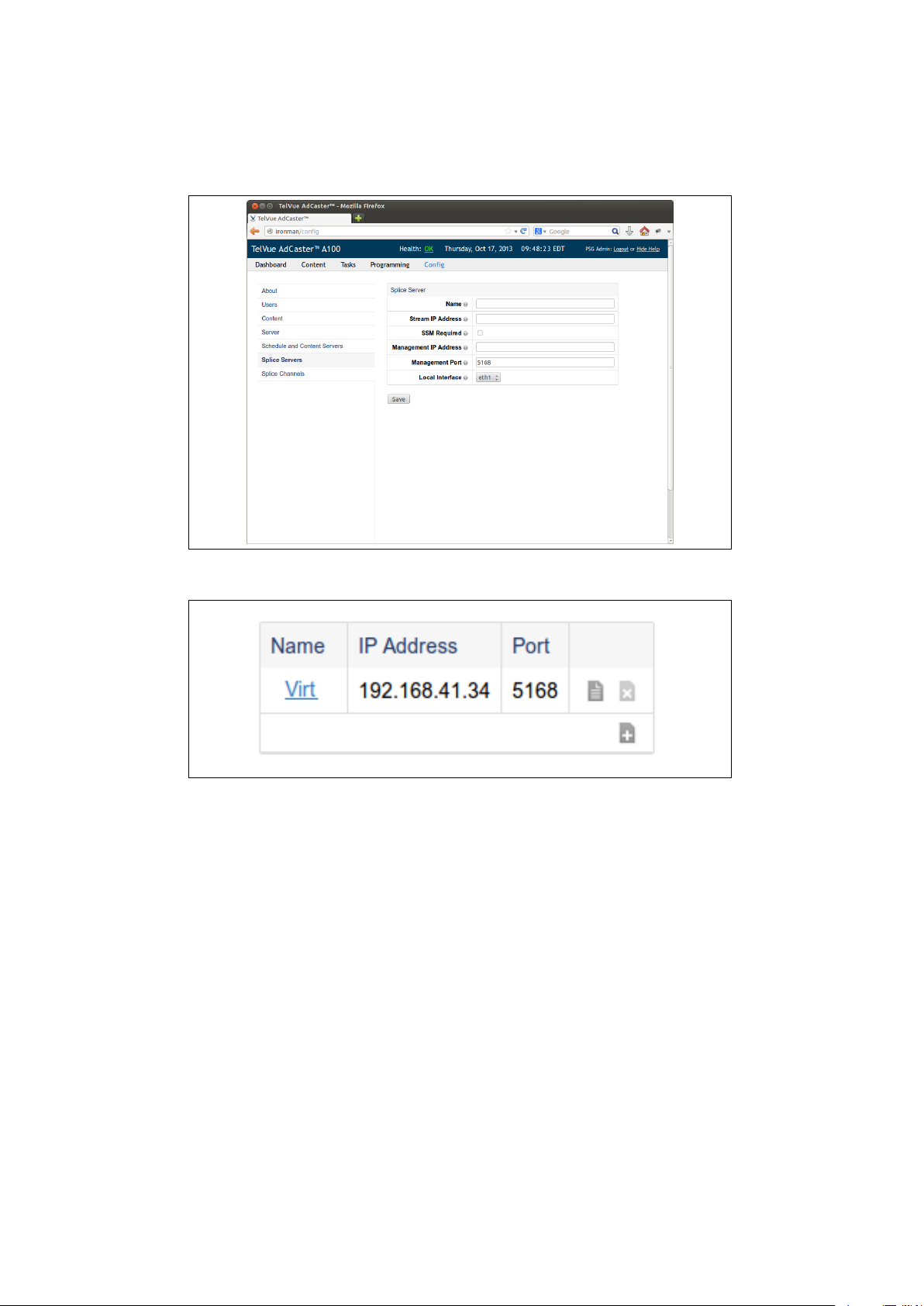
Figure 3.3: Set the name, stream and management ip address, port number,
and interface for the SCTE-30 connection.
Figure 3.4: The splicer now appears in the table. You can edit it or remove it
from here as well.
Once you have the correct parameters entered for your channel. Press the
save button. You will see the new channel in the list. From here you can add
more channels, edit existing channels, and remove unused channels.
16
Page 18
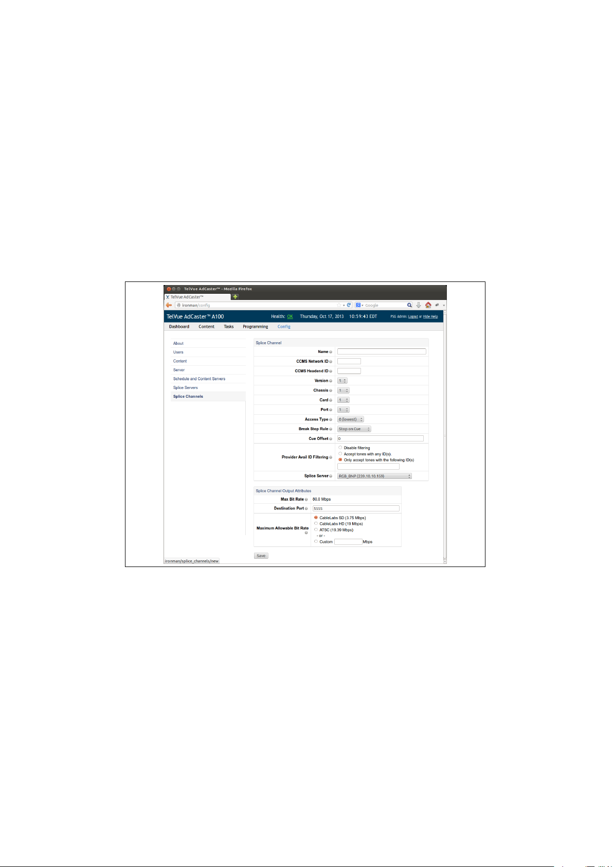
Figure 3.5: The splice channel configuration screen. Here is where you set all
of the options for the channel and associate it with the splicer it belongs to.
17
Page 19

Chapter 4
Schedules and Content
4.1 Importing schedules from the programming
tab
The AdCaster web app interface allows you to manually import a “.SCH” schedule file from your desktop. After logging into the web app, click on the “Programming” tab at the top of the screen. This will bring you to a page like the
one in figure 4.1. If you already have content scheduled you will see it here. If
not you can add a schedule for any configured channel by clicking the “Import
Schedule” link in the upper left hand corner. See figure 4.2 for help locating the
link.
Figure 4.1: The programming tab showing what content has been scheduled.
18
Page 20

Figure 4.2: Clicking this link will allow you to import a schedule file from the
desktop.
After clicking the link, a file chooser window will pop up and allow you to
browse the local file system and choose the appropriate schedule file. After you
have found the file, the server will begin importing it. Once the schedule has
been imported you will see the scheduled items in the “Programming” tab.
4.2 Scheduling a window manually
Another way to create a schedule is to create one manually through our window
scheduling interface. To begin click on the “Schedule a window” link located at
the top of the “Programming” tab. Refer to figure 4.3 for exactly what to click.
Figure 4.3: Clicking this link will allow you to schedule a window manually.
Clicking on the link will bring you to the window scheduling page. From
here you can select which channel you would like to apply this new window.
Then you can select a start date, and end date. Then click the save button.
Now you have a new window ready. Next you must ad breaks to the window,
and select which content you would like to play during the break.
To add an ad break, click on the plus (+) symbol in the lower right hand
corner. The next page that you see will allow you to select the content that you
want to add to this break. You can also specify an optional start time. This
start time is only used for logging, and does not affect the play out of the ad
from a scte30 CUE.
19
Page 21

Figure 4.4: Choose the channel, start time, and end time for the new window.
Figure 4.5: The window has been created, you breaks must be added. Click
the plus (+) symbol in the lower right hand corner to add a break.
20
Page 22

Figure 4.6: Add content to the new break for the window. Once you have
selected your content press the ’+’ button to add it to the break.
21
Page 23

Part III
Using the AdCaster
Dashboard
TM
22
Page 24

Chapter 5
Dashboard Overview
5.1 A Tour of the Dashboard features
The dashboard provides a real-time, color-coded heads up display that gives
and overview of everything that is happening with the AdCaster unit. From
this single screen you can monitor all splice channels at once, and get instant
feedback on any issues that may occur (figure 5.1).
Figure 5.1: The AdCaster dashboard provides real time status for all connected
splice channels and system health.
The top of the dashboard is a navigation bar that can be used to go to the
other pages, view system health, and see the local time on the AdCaster. In
the center is the channel grid which is where you can see the real-time status
of each channel configured on the system. Each column in the grid represents
a single channel. At the top of each column is the name of the channel. In the
center of the grid there is a thick black line. That line represents the current
time. All events above the line are in the past, and all events below the line are
in the future.
23
Page 25

5.2 Configuring Filters
At the top of the dashboard page, below the navigation bar you will see two
links. The first link is “Show Dashboard Filters”. If you click that link you will
see a new menu open and allow you to configure the channel grid (figure 5.2).
Figure 5.2: The “Show Dashboard Filters” drop down can be used to configure
what channels are shown on the channel grid, as well as set the colors for various
alerts.
From the “Show Dashboard Filters” page you can configure the colors of
the various notifications, select which channels you want to view, and configure
how many past and future breaks to display. Each box in the grid represents a
single break. A break can contain one or more ad spots.
5.3 Getting Detailed Information
If you want to know the specifics of any break on the grid, you can simply click
it to bring up the “Break Information” dialog (figure 5.3). This dialog will show
the filenames of the ads associated with this break, as well as their playout
status. It will also show the window information and which break it was in that
window.
From within the dialog, If you click on the name of the ad, you will be taken
to that ads content page (figure 5.4). From here you can see details about the
file such as run time and file size. It will also display the times for the next five
playouts, and the previous five successful playouts.
Also from within the “Break Information” dialog, you can click on the status
of any file and be taken to that breaks as-run page (figure 5.5). This page will
24
Page 26
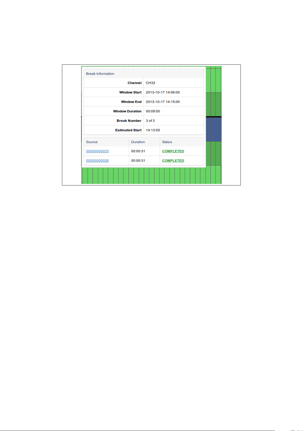
Figure 5.3: The “Break Information” dialog will show you everything about a
selected break on the channel grid.
give detailed information about the specific window, and all of the breaks in that
window. It will report the window start and end time, as well as the number
of scte-30 “tones” received for that window. You can also expand the playout
rows to see the exact begin and end times for each ad in a break.
25
Page 27
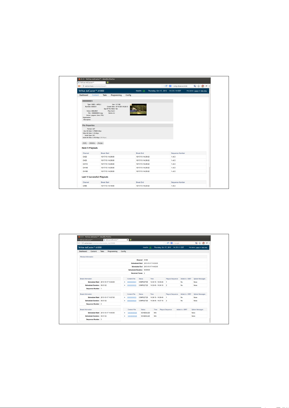
Figure 5.4: The ad content page showing the details of the file, and its last
and future playouts.
Figure 5.5: The as-run page showing detailed information for the window and
each break associated with it.
26
 Loading...