

Telular TG-9 User Manual
Telguard® Digital Model TG-9
Digital Cellular Alarm Communicator
Installation and Operating Instructions
Important: Read Before Installing Model TG-9
The following tools are required for installation:
Screwdriver and appropriate mounting screws
Confirm the presence of all required parts:
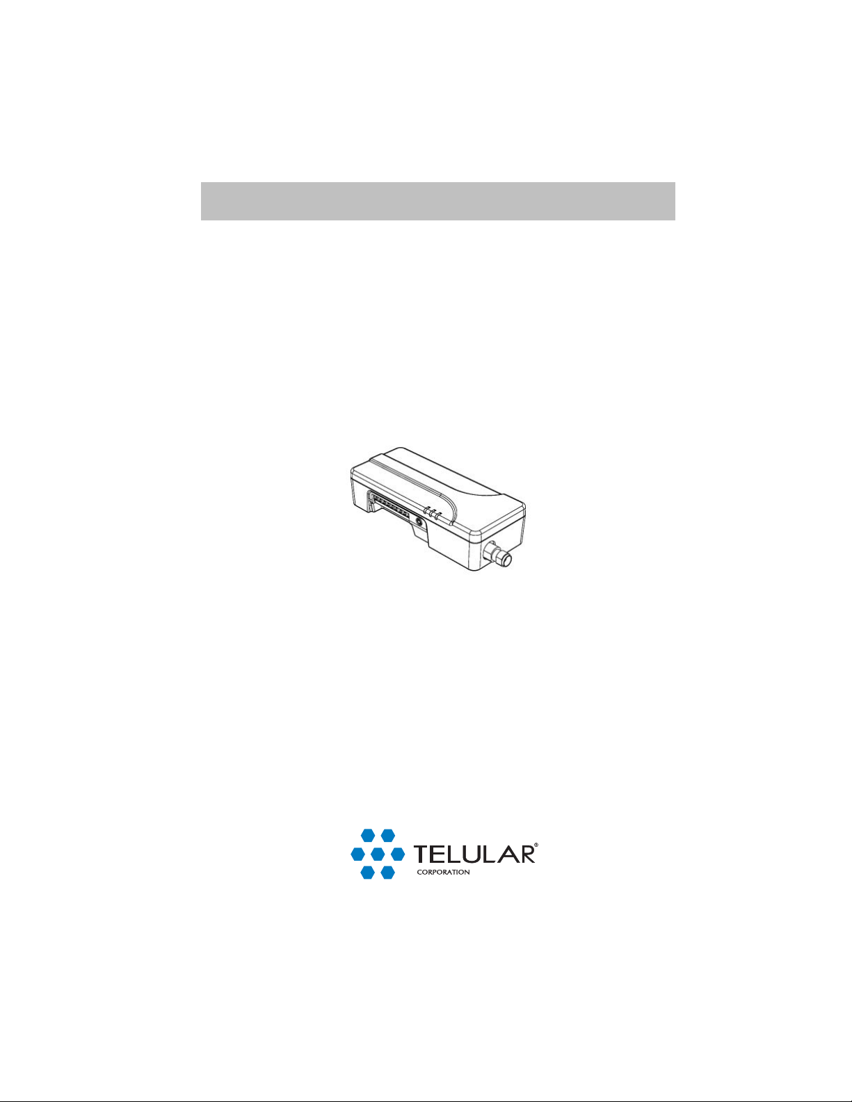
• 1x TG-9 Cellular Alarm Communicator
• 1x Dipole Antenna
• 6x End-Of-Line resistors
Before going to the site:
• Fill out and submit the Telular TG-9 Digital Cellular Service Activation
Form.
• Fax the activation form to 678-945-1651 or submit the activation form
on the internet at Telular.com
Note:
Ensure that you have the correct wiring diagram for the selected TG-9
Operation Profile.
Technical Support: 800-229-2326
M-F 8:00AM – 8:00PM EST
Saturday 9:00 AM – 5:00 PM EST
April 27, 2007
56037002 - 1 - © 2007 Telular Corporation

Device Profile Options
The Telguard TG-9 Profile is stored in the Telular Communications Center and defines how each unit
operates. One profile may be used for multiple units. The profile is uploaded to the Telguard TG-9
when it is activated, there is no field programming needed.
Trip and Restore Reporting
The TG-9 is programmed to send trips on all zones (not restorals). The profile can be set so that
restores are transmitted. Changes will affect all trip zones.
• Profile Options: Report Restoral / Do Not Report Restoral
Zone 1: Trip Input or Bell Input
Zone 1 on the TG-9 can be programmed as a normal trip input (default), or as a Bell Input. Bell
input is ANSI standard Fire (3 rings, pause) and Burg (steady on).
• Profile Options: Trip Input / Bell Input
Note: Do not connect E.O.L. resistor if using bell input.
Note: If using Bell input, Bell must be connected per Table 1 on page 5 before
activating. Make sure there are no Bell alarms in progress before activating.
Zone 6: Trip Input or Shunt
Zone 6 on the TG-9 can be used as a shunt (default) or as a normal trip input. When in shunt
mode, a switch can be used to enable or disable alarm functions. When the switch is in an “ON or
SHORTED” state alarm functions will be disabled.
• Profile Options: Shunt / Trip Input
Report Shunt Activity / Do Not Report Shunt Activity
Zones 2 - 5: Trip inputs
Zones 2 - 5 are standard trip inputs.
Swinger Option
The TG-9 can be programmed for a swinger setting. Should a single zone trip more than X times
in Y minutes, the system will send no more events for that zone until Z minutes have passed with
no trips.
• Profile Options: Swinger Option On / Off
Number of Events (1 – 99)
During Time Period (1 – 99 Minutes)
Time to Restore (1 – 99 Minutes)
STC Trip Output
The STC trip output is a Normally Closed contact with four modes.
Mode 1: It acts as a supervisory output, monitoring for No Cellular Service (NSC), Power Failure
(PFC), Failure to Communicate (RFC),
Mode 2: It acts as an alarm or bell driver, tripping the alarm system or sounding an alarm bell
when a zone or zones on the TG-9 are tripped. Output will time out after 15 minutes.
Mode 3: It acts as an auxiliary output, which will close or open based on incoming signals.
Mode 4: the output is disabled
• Profile Options: Mode 1 / Mode 2 / Mode 3 / Mode 4
56037002 - 2 - © 2007 Telular Corporation
 Loading...