

Telular SX5T CDMA, SX5T-CDMA2000, CDMA SX5T-500C, SX5T-505C, SX5T-535C User Manual
...
11/19/04 Part Number 56029901
Phonecell
®
SX5TCDMA2000
®
1X
Fixed Wireless T erminal
SX5T -505C/-535C D
UAL
-B
AND
800/1900 MHZCDMA
SX5T -500C S
INGLE
-B
AND
800 MHZCDMA
SX5T -500C S
INGLE
-B
AND
1900 MHZCDMA
USER MANUAL
Phonecell®SX5TCDMA2000 ii User Manual
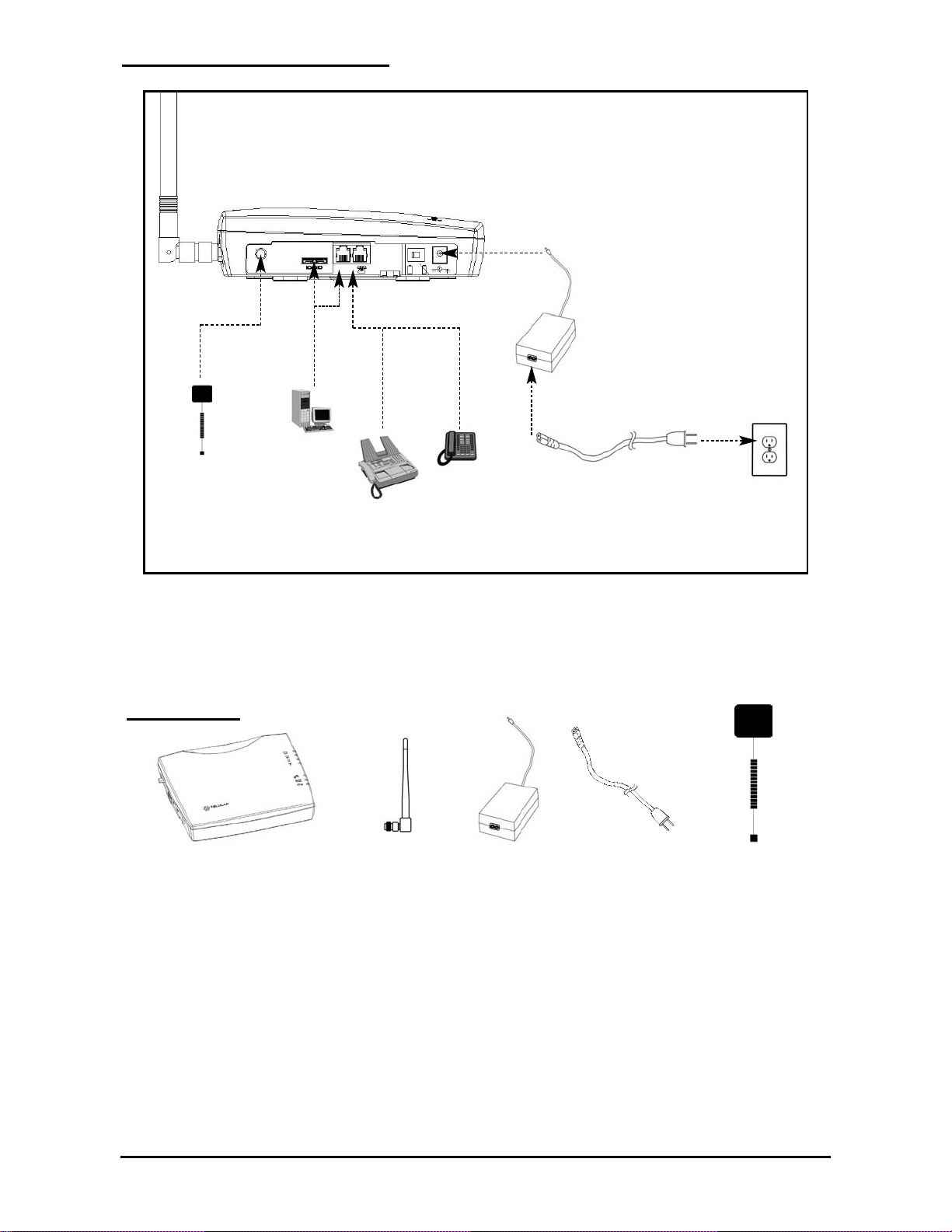
Quick Connection Diagram
Before installing the Phonecell®SX5T, carefully remove the contents from the shipping carton and
check for evidence of shipping damage. If damage is found, contact your Authorized T elular
Distributor or shipping agent immediately.
CONTENTS
Phonecell®SX5T CDMA FWT Spike Antenna Power Supply
or BBU
AC Power Cord
GPS Antenna
(Optional)
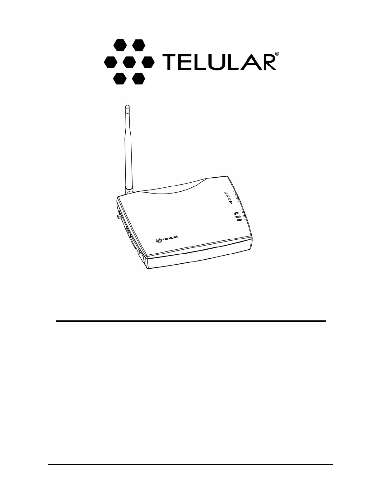
SX5T Fixed Wireless T erminal

Phonecell®SX5TCDMA2000 iii User Manual
SAFE OPERATION INSTRUCTIONS
IMPORTANT!Before installing or operating this product, read the SAFETY INFORMATION
section on page 36of this manual.
• Install the unit indoors.
• Install the unit on a hard, flat surface for proper ventilation.
• Do not expose the unit to rain or moisture.
• Do not place the unit on or close to sources of heat.
IMPORTANT NOTICES
TERMS AND CONDITIONS FOR USE OF PHONECELL®PRODUCTS ("Product")
These T erms and Conditions are a legal contract between you and Telular Corporation for the title to
and use of the Product. BYRETAINING AND USING THE PRODUCTAFTER RECEIPTOF IT ,
YOU AGREE TO THE TERMS AND CONDITIONS INCLUDING WARRANTYDISCLAIMERS,
LIMIT ATIONS OF LIABILITYAND INDEMNIFICATION PROVISIONS BELOW . IF YOU DO NOT
AGREE TO THE TERMS AND CONDITIONS, DO NOTUSE THE PRODUCTAND IMMEDIA TEL Y
RETURN THE UNUSED PRODUCTFOR ACOMPLETE REFUND. Y ou agree to accept sole
responsibility for any misuse of the Product by you; and, in addition, any negligent or illegal act or
omission of your or your agents, contractors, servants, employees, or other users of the Product so
long as the Product was obtained from you, in the use and operation of the Product.
INDEMNIFICA TION OF TELULAR CORPORATION ("TELULAR")
YOU SHALL INDEMNIFY, DEFEND AND HOLD HARMLESS TELULAR FOR ANY OF THE COST, INCLUDING
REASONABLE ATTORNEYS' FEES, AND FROM CLAIMS ARISING OUT OF YOU, YOUR CLIENTS' OR OTHER THIRD
PARTIES' USE OR OPERATION OF THE PRODUCT: (i) FOR MISUSE OR IN A MANNER NOT CONTEMPLATED BY YOU
AND TELULAR OR INCONSISTENT WITH THE PROVISIONS OF THIS MANUAL; (ii) IN AN ILLEGAL MANNER OR
AGAINST PUBLIC POLICY; (iii) IN A MANNER SPECIFICALLY UNAUTHORIZED IN THIS MANUAL; (iv) IN A MANNER
HARMFUL OR DANGEROUS TO THIRD PARTIES; (v) FROM CLAIMS BY ANYONE RESPECTING PROBLEMS,
ERRORS OR MISTAKES OF THE PRODUCT; OR (vi) COMBINATION OF THE PRODUCT WITH MATERIAL,
MODIFICATION OF THE PRODUCT OR USE OF THE PRODUCT IN AN ENVIRONMENT NOT PROVIDED, OR
PERMITTED, BY TELULAR IN WRITING. THE PARTIES SHALL GIVE EACH OTHER PROMPT NOTICE OF ANY SUCH
COST OR CLAIMS AND COOPERATE, EACH WITH THE OTHER, TO EFFECTUATE THIS INDEMNIFICATION,
DEFENSE AND HOLD HARMLESS.
Telular Corporation
Corporate Headquarters
647 North Lakeview Parkway
Vernon Hills, Illinois 60061, USA
Technical Support
T el: 847-247-9400 • Fax: 847-247-0021
E-mail: support@telular.com • http://www .telular.com
Part Number 56029901 ©2004 T elular Corporation, All Rights Reserved
PLEASE SEE THE IMPORT ANT NOTICESAND SAFETYINFORMATION SECTIONS
OF THIS MANUALFOR IMPORTANT INFORMA TION ON USE AND
INDEMNIFICA TION. FOR WARRANTYINFORMA TION, PLEASE SEE THE LIMITED
COMMERCIALWARRANTYCARD WHICH WAS P ACKAGED WITH YOUR DEVICE.

Phonecell®SX5TCDMA2000 iv User Manual
Table of Contents
Quick Connection Diagram..................................................................................................ii
Safe Operation Instructions................................................................................................iii
Important Notices................................................................................................................iii
Setup......................................................................................................................................1
RUIM Card Installation (RUIM Model Only) ....................................................................................1
Connecting an SX5T Model With a Power Supply..........................................................................2
Emergency Batteries .......................................................................................................................3
Connecting an SX5T Model With a BBU (Backup Battery Unit).....................................................4
SX5T Location and Installation ........................................................................................................5
Wall Mounting..................................................................................................................................5
GPS Antenna Mounting (optional on SX5T-505C/-535C only) ........................................................6
Direct Connection: Phone, Fax and Data .......................................................................................7
Connection via Wall Jacks...............................................................................................................7
Getting to Know Your SX5T .................................................................................................8
LED Status Indicators......................................................................................................................8
Important Dial Tones........................................................................................................................9
Using the SX5T ...................................................................................................................10
Making Calls..................................................................................................................................10
Receiving Calls..............................................................................................................................10
Ending Calls...................................................................................................................................10
Using In-Call Features...................................................................................................................10
Accessing Your Voicemail..............................................................................................................11
Making a Three-Way Call..............................................................................................................11
Using Call Forwarding....................................................................................................................11
Adjusting Your Phone’s Settings......................................................................................12
Volume Level.................................................................................................................................12
Entering Configuration Mode .........................................................................................................12
Changing the Lock Code...............................................................................................................12
Audio Line Level............................................................................................................................13
Auto-Send Delay............................................................................................................................13
Frequently Dialed Numbers (Zero Delay Dialing)..........................................................................13
Call Barring....................................................................................................................................13
Call Restrict (SX5T-500C only)......................................................................................................14
Dial Tone After Remote Disconnect (DTARD)...............................................................................14
Hotline............................................................................................................................................15
One-Minute Alert............................................................................................................................15
TTY Use.........................................................................................................................................15
Voicemail Number..........................................................................................................................16
One-Touch Voicemail Retrieval .....................................................................................................16
Restore User Defaults...................................................................................................................16
Using Additional Hardware Devices.................................................................................17
Using an External Answering Machine..........................................................................................17
Setting Up Data Transfer for a Digital Video Recorder (DVR) or Satellite Receiver.....................17
Using a Fax Machine With Your SX5T ..........................................................................................17
Windows XP/Windows 2000 Setup for Data & PC Fax ...................................................18
Windows 98 Setup for Data & PC Fax..............................................................................24
Sending/Receiving a PC Fax.............................................................................................28
Sending/Receiving 1X Data ...............................................................................................29
Sending/Receiving Circuit Switched Data........................................................................30
SX5T-500C Advanced Programming Settings .................................................................31
SX5T Troubleshooting........................................................................................................35
Conformance Statements ..................................................................................................36
Safety Information..............................................................................................................36
Phonecell®SX5TCDMA2000 1 User Manual
Setup
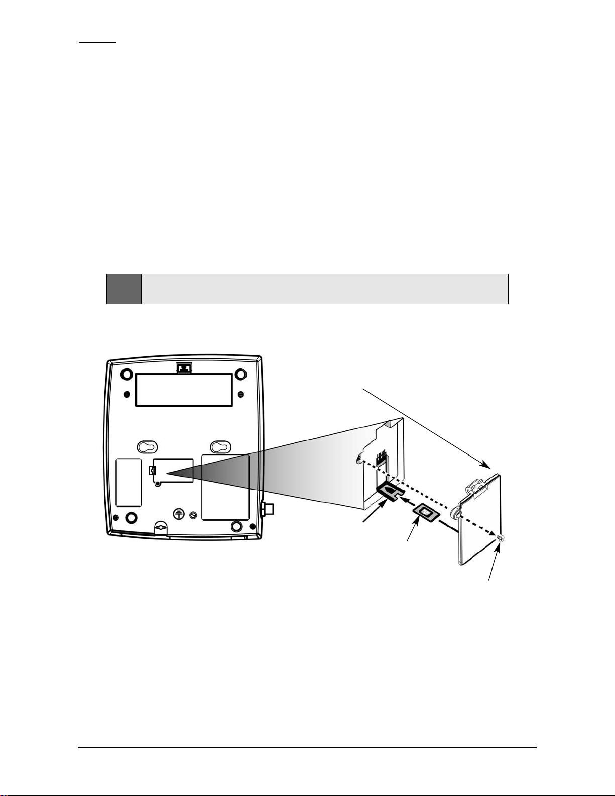
RUIM Card Installation (RUIM Model Only)
Consult your service provider to determine if your unit requires the use of a RUIM (Removable User
Identity Module) card. If it is a RUIM model, your SX5Twill only be able to make emergency calls until
you install a RUIM card. It will not receive calls or allow non-emergency outgoing calls without the
RUIM card installed.
1. Remove the power supply if it has already been connected. (The power supply must be
removed whenever a RUIM Card is removed or installed.) If your unit has emergency batteries
installed, make sure the AC/Batter Switch is in the AC Power position (see “Battery Operation”
on page 3).
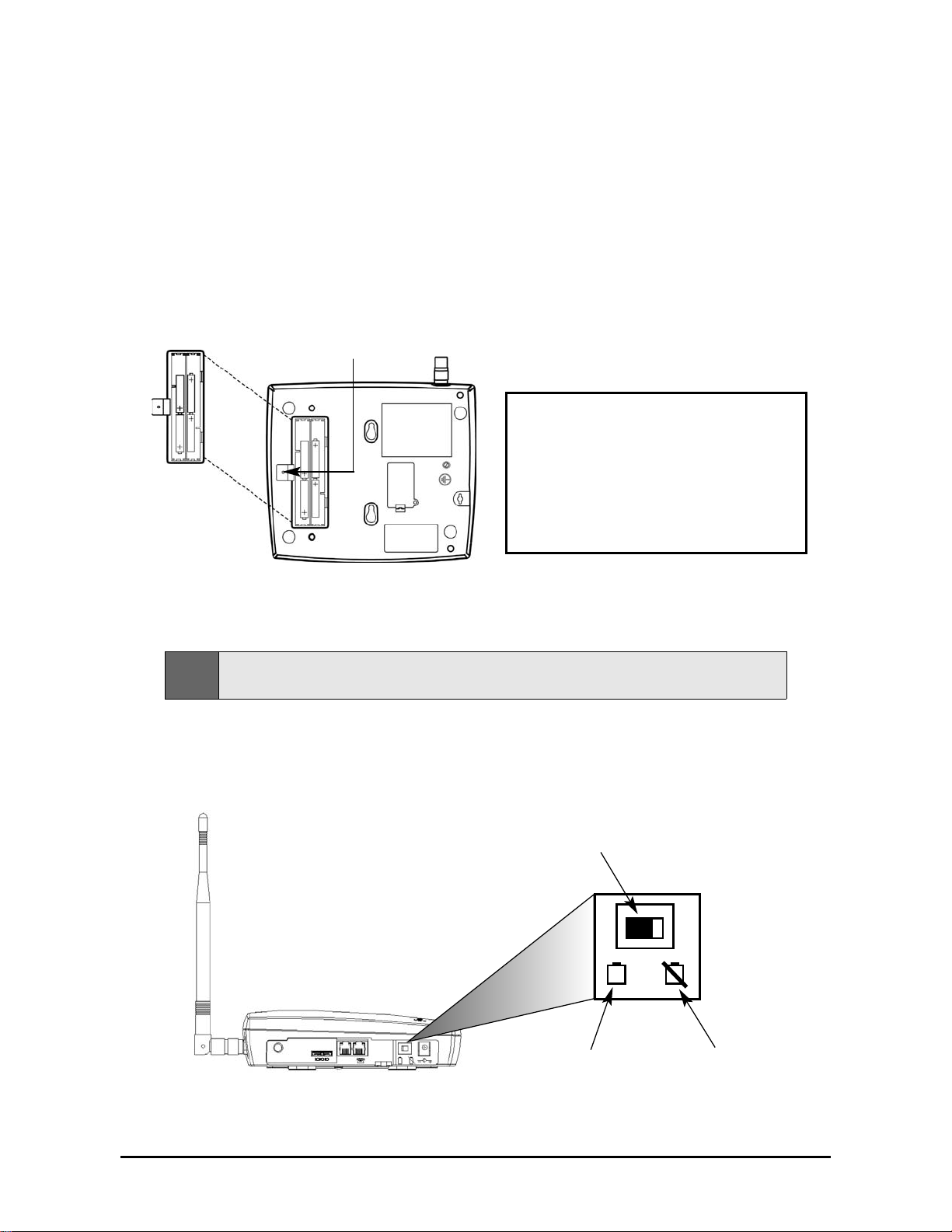
2. Remove the RUIM compartment cover - see Figure 1.
3. Open the RUIM compartment holder .
4. Line up the RUIM card with the arrow on the RUIM card holder - see Figure 2.
5. Gently insert the RUIM card in the slot of the RUIM card holder.
6. Close the RUIM card holder.
7. Reattach the RUIM compartment cover , closing it with the separate cover screw provided.
RUIM
Compartment
Cover
RUIM Card
Holder
RUIM Card
Cover Screw
Figure 2 - Install the RUIM Card.Figure 1 - RUIM Compartment.
Note:
Do not force the RUIM card holder shut. Make sure the RUIM card is aligned properly with the
directional arrow on the holder.
Phonecell®SX5TCDMA2000 2 User Manual
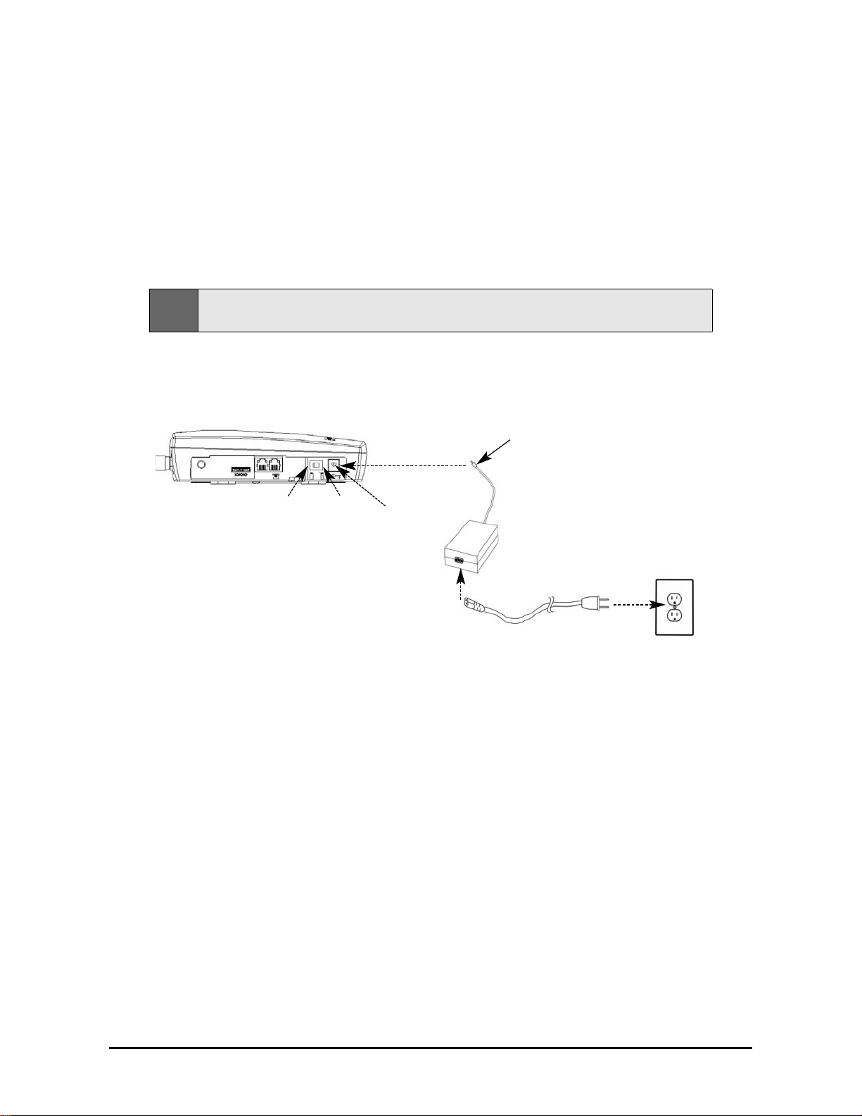
Connecting an SX5T Model With a PowerSupply
Y our SX5Thas either a Power Supply (part #74007301) or a Battery Backup Unit
(BBU; part #74006803). If your unit uses a Power Supply , please follow the instructions
below to connect the SX5Tto your AC power . If it uses a BBU, please see “Connecting an SX5T
Model With a BBU” on page 4.
T o connect an SX5T model with a Power Supply:
1. Connect the barrel connector of the power supply to the AC power input recept acle of the SX5T
- see Figure 3.
2. Plug the AC power cord into the power supply .
3. Plug the AC power cord into the AC Power outlet.
4. Check the cellular signal strength and move the unit until you achieve the best signal
possible - see LED Status Indicatorson page 8for more information.
Figure 3 –
Connect the SX5T to AC Power.
AC Power
AC Power
Position
Battery
Position
AC Power Cord
Power
Supply
Barrel Connector
AC Power
Input Receptacle
Hint:
If there are no emergency batteries in the SX5T , it will only power on if the AC/Battery switch is in the
AC power position -
see Figure 5 on page 3for a detailed view.
Phonecell®SX5TCDMA2000 3 User Manual
Emergency Batteries
If your SX5Thas a Power Supply, you may install emergency batteries to power the device in the
event of a power outage.
Do not install emergency batteries if your SX5T has a BBU.The SX5T
will not automatically switch to battery if AC power fails; you must flip the AC/Battery switch to battery
operation - see Figure 5.
T o install emergency batteries:
1. Remove the battery access door screw located on the bottom of the unit - see Figure 4.
2. Press the battery access door tabs and remove the battery access door .
3. Install 4 “AA” alkaline batteries (not supplied) - see Figure 4.
4. Reinstall the battery access door using the screw .
Battery Operation
SX5Tmodels with Power Supplies will not automatically switch from AC to battery upon loss of AC
power. The AC/Battery switch must be changed manually - see Figure 5. Battery power will provide
up to 3.5 hours of standby or up to one hour of talk time, depending on the SX5Tmodel.
Figure 5 – SX5TAC/Battery switch.
AC/Battery Switch
Battery Position AC Power Position
Note:
If you use rechargeable “AA” batteries with the SX5T , they must be recharged externally (the unit will
not recharge them automatically).
Battery
Access
Door
Battery Access
Door Screw
Figure 4 – SX5T battery installation.
WARNING!
Only “AA” alkaline batteries should be
used with the Phonecell®SX5T.
Use of any other batteries may result in
fire and/or other damage to the unit.
Phonecell®SX5TCDMA2000 4 User Manual
Connecting an SX5T Model With a BBU(Backup Battery Unit)
Y our SX5Thas either a Power Supply (part #74007301) or a Battery Backup Unit
(BBU; part #74006803).
If your model has a BBU, it is shipped with the battery disconnected to prevent if from being
prematurely drained.
The BBU must not be connected to a SX5T or to AC power when you
connect or replace the battery . Connecting the wrong wires to the battery terminals may
cause severe damage to the device.
T o connect an SX5T model with a BBU:
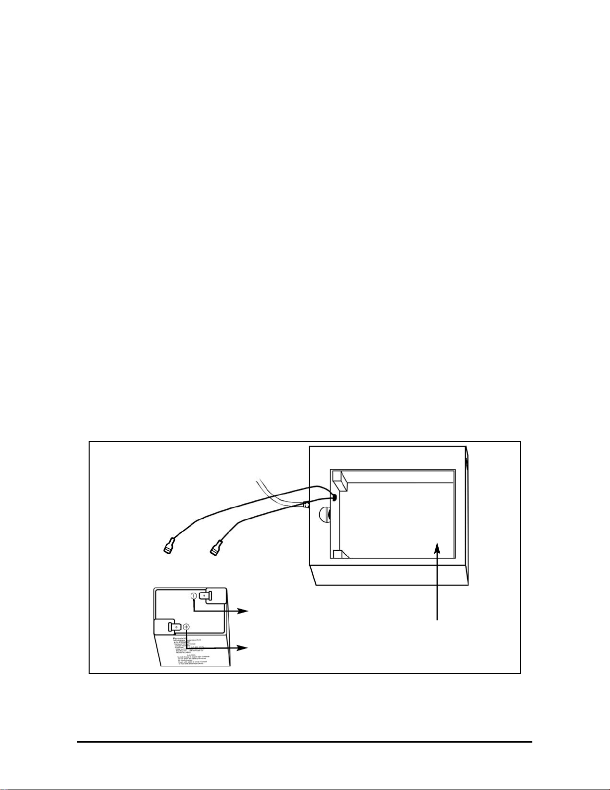
1. Make sure the BBU is disconnected from the SX5Tand the AC power cord.
2. Unlatch the battery compartment cover by using a coin to rotate its latch to the open position.
3. Remove the cover.
4. Connect the black wire (-) in the battery compartment to the black terminal (-) on the battery -
see Figure 6.
5. Connect the red wire (+) in the battery compartment to the red terminal (+) on the battery -
see Figure 6.
6. Insert the battery into the battery compartment.
7. Reattach the compartment cover and secure it with the cover latch.
8. Insert the barrel connector of the Power Supply and Battery Backup Unit’s cord into the SX5T’s
Power Input - see Figure 3on page 2.
9. Connect the AC power cord to the Power Supply and Battery Backup Unit, then plug it into a
power outlet - see Figure 3on page 2.
10. Press the Battery Power Switch on the BBU to the ON( |/ right) position.
11. Slide the Power Switch on the SX5Tto the ON (right) position.
12. Check the cellular signal strength and move the unit until you achieve the best signal
possible - see LED Status Indicatorson page 8for more information.
Figure 6 – Connecting the battery.
Red Wire (+)
Black Wire (-)
Battery Compartment
Red T erminal (-)
Black T erminal (-)
Phonecell®SX5TCDMA2000 5 User Manual
SX5T Location and Installation
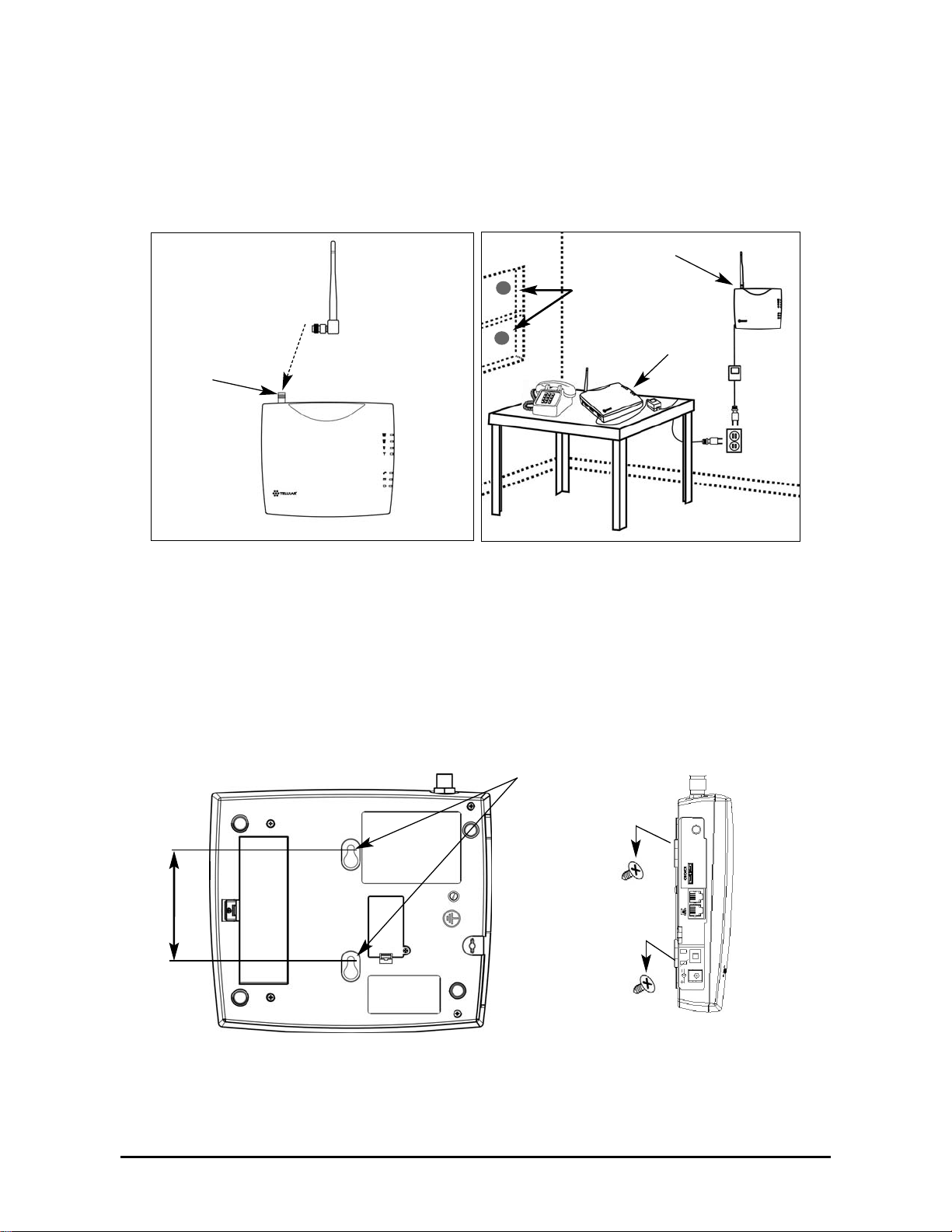
The SX5Tcomes with a standard spike antenna (TNC) - see Figure 7. For optimal signal strength,
choose a location that is above ground and as close to windows (or exterior walls) as possible - see
Figure 8. Place the unit where you receive the best signal strength possible. (Cellular signal strength
is displayed by the Received Signal Strength Indicator [RSSI] LEDs on the unit - see LED S tatus
Indicatorson page 8 for more information.)
1. Connect the antenna to the terminal - see Figure 7.
2. Finger-tighten the antenna. Do not over-tighten the antenna.
Wall Mounting
1.
Mark two hole locations 98.5 mm (3-7/8 inches) vertically ap art and drill two holes into the wall.
2. Install the screws (not supplied) into the wall, leaving a gap (approximately 3 mm (1/8 inch))
between screw head and wall.
3. Align the mounting holes with the screws and mount the SX5Tonto the screws - see Figures 9
and 10.
Figure 9 – SX5T mounting holes.
Mounting Holes
98,5 mm (3 7/8”)
Figure 10 – Mount the SX5T onto the screws.
Figure 8 – Typical SX5Tinstallations.
Wall Mount
Table Mount
GPS Brackets
Figure 7 –
SX5T antenna connection.
Spike
antenna
TNC Antenna
Connector
Phonecell®SX5TCDMA2000 6 User Manual
GPS Antenna Mounting (optional on SX5T -505C/-535C only)
T o satisfy the FCC's Enhanced 91 1 (E-91 1) Phase II mandate, SX5T-505C and 535C models
distributed in the USAinclude an optional GPS antenna with a mounting bracket and suction cups.
The GPS antenna uses satellite technology during emergency calls to automatically report your
location to a 91 1 dispatcher within 50-100 meters in most cases. For this feature to function, you must
properly mount the GPS antennaon a window as described below in addition to the standard antenna
used for cellular system operation.
1. Mount the bracket on a window with good line of sight (no obstructions to the sky) using the
suction cups. Asmall amount of water or petroleum jelly applied to the window surface of the
suction cups will improve their long-term adhesion to the window - see Figure 8 on page 5.
2. Place the antenna on the topside center of the bracket. The bracket is tilted to aim the
antenna out the window and toward the sky .
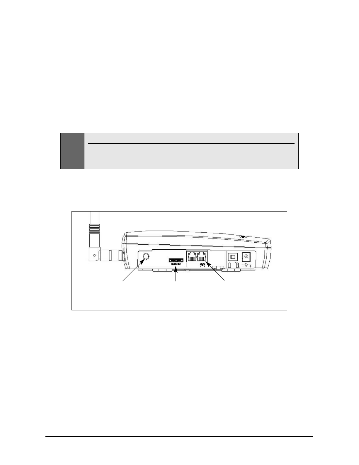
3. Connect the antenna to the GPS Connector on the side panel of the SX5T- see Figure 1 1.
GPS Connector
(SX5T-505C/
-535C Only)
Figure 11 – Connectors
Phone Jacks
(RJ11)
Data Port
(Serial or USB)
Note:
Installation of the GPS antenna is not required for normal operation of the SX5T .
Since E-911 service may not be available in all areas, 91 1 or other emergency calls may not
automatically provide a location. You must be prepared to provide an address during any
emergency calls.

Phonecell®SX5TCDMA2000 7 User Manual
Direct Connection: Phone, Fax and Data
1. Connect a phone to either of your SX5T’s phone (RJ1 1) jacks using a standard telephone cord -
see Figure 1 1 on page 6.
2. If desired, connect your SX5T’s other phone (RJ1 1) jack to a second telephone or a fax machine
using a standard telephone cord - see Figure 1 1on page 6.
3. If desired, connect a computer to the SX5T . Y ou may either:
· Use a T elular USB cable (part #1L01A043 or 81025901) to connect the computer’s USB port
to the SX5T’s data port;
· Use a T elular serial cable (part #1L01A042 or 81025801) to connect the computer’s serial
port to the SX5T’s data port;
· Or use a standard telephone cord to connect the computer’s modem out port to either of the
SX5T’s phone (RJ1 1) jacks.
Contact your service provider to determine what wireless data transfer services are available.
For more information on data connections, see “Windows XP/Windows 2000 Setup for Data &
PC Fax” on page 18or “Windows 98 Setup for Data & PC Fax” on page 24.
Connection via Wall Jacks
If you do not have local phone service, you may use your SX5Tto provide a connection to your
wireless service for devices that are plugged into your wall jacks.
1. Connect either of your SX5T’s phone (RJ1 1) jacks to any wall jack using a standard telephone
cord - see Figure 1 1on page 6.
2. If desired, connect your SX5T’s other phone (RJ1 1) jack to a telephone or fax machine using a
standard telephone cord - see Figure 1 1on page 6.
3. Connect additional phones, a fax machine and/or a computer modem to any available wall
jacks. Contact your service provider to determine what wireless data transfer services are
available.
Important:
DO NOT CONNECT YOUR SX5T TO A WALL JACK IF YOU HAVE OUTSIDE SERVICE
(I.E., A DIAL TONE) AT YOUR WALL JACK.
Y our SX5Twill not function properly and may
become damaged if outside phone service has not been disconnected.
Phonecell®SX5TCDMA2000 8 User Manual
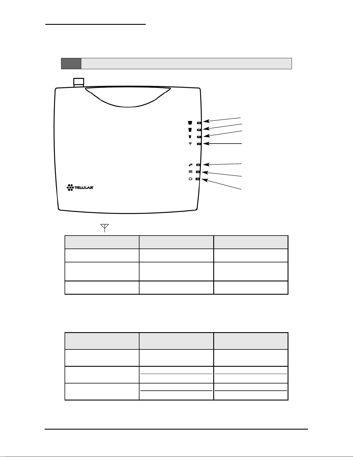
Getting to Know Your SX5T
LEDStatus Indicators
The LED indicators are activated when the SX5Tis powered on. The following tables describe the
modes and operation of the indicators.
Service Indicator
*Contact your service provider to verify that service has been activated.
Signal Strength Indicator (Received Signal Strength Indicator – RSSI)
Signal Strength LEDs
Activity Cellular Signal Strength
Signal Strength 1 (RSSI 1)
Continuous Poor
Signal Strength 2 (RSSI 2)
Flashing
Continuous
Fair
Good
Signal Strength 3 (RSSI 3)
Flashing
Continuous
Very Good
Best
LED Color
Activity Description
Green Continuous Full Service
Amber
Continuous or Flashing
(network dependent)
Roaming
Red Continuous No Service*
Signal Strength 3
Signal Strength 2
Signal Strength 1
Service Indicator
Call Activity Indicator
Message Indicator
AC Power/Battery
Indicator
Note:
If you are getting no service, contact your service provider for more information.
Phonecell®SX5TCDMA2000 9 User Manual
Call Activity Indicator
Message Indicator
AC Power/Battery Indicator
Important Dial T ones
Y ou may hear these tones through the receiver when your phone is off-hook:
Steady T one (dial tone): Service – Indicates that your phone is ready for use.
Fast Beeping T one: No Service – Indicates that there is no service available.
Short T one: Call Waiting – During an active call, a short tone indicates that you have another
incoming call.
Pulsed Dial T one, followed by a Steady Dial Tone:Voicemail – Indicates that you have a new
voicemail message.
Color Activity Description
Green Continuous AC power applied
Amber Continuous
Battery level good
(battery switch on)
Amber/Green Alternating
Battery level poor
(battery switch on)
LED Color Activity Description
Green Flashing New voicemail
LED Color Activity Description
Green
Flashing
(phone will also be ringing)
Incoming call
Green Continuous In an active call
Green Fast Flashing Processing data call
Amber Continuous Programming Mode

Phonecell®SX5TCDMA2000 10 User Manual
Using the SX5T
Once you have installed and activated your SX5T , you’ll be ready to make and receive calls, set up
voicemail, and send and receive faxes. This section explains how to use the features of the SX5Tfor
all your communications.
Making Calls
T o make a call:
1. Pick up the telephone handset. (The phone is now “off-hook.”)
2. Listen for a dial tone. (If you hear a No Service tone [fast beeping], hang up and try again. If the
No Service tone continues, contact your service provider to verify that cellular service is
available.)
3. Dial a phone number . (When you have finished dialing, the call will be sent automatically.)
Receiving Calls
• When the telephone rings, pick up the handset and begin talking.
Ending Calls
• When you are finished with a call, hang up the phone by placing the handset back on the
telephone cradle or by pressing the Offor Endbutton.
Using In-Call Features
T o place a call on hold:
• During a call, press the
Flashkey on your handset (if your phone doesn’t have a Flash key,
press and release the switch-hook).
· If you hang up your phone when a call is on hold, the call will be disconnected.
T o retrieve a call on hold:
• Press the
Flashkey on your phone (or press and release the switch-hook).
T o answer a call waiting call:
• When you’re on an active call and a new incoming call arrives, you will hear a short tone on your
phone. T o place the current call on hold and answer the incoming call, press the
Flashkey on
your phone (or press and release the switch-hook). (T o switch between calls, simply repeat the
process.)
T o answer a call when you are dialing or with the phone off the hook:
• If a call comes in while you are dialing or when you have the phone off the hook, you will hear a
call waiting tone on your phone. T o answer the incoming call, press the
Flashkey on your
phone (or press and release the switch-hook).
Note:
Call Hold and Call Waiting are not available with all service providers. These services may not be
available if you are using your SX5Tin a roaming area. T o determine these services’availability in your
area, contact your service provider.
Tip:
Pressing the
Flash
key or pressing and releasing the switch-hook after dialing a number will send
the call immediately.
 Loading...