

Telular GXT5002C User Manual
SkyBitz CMANRAP027 GXT5002C Sheet & Post Nose Trailer Install Guide Rev C 12/20/2017 1
CMANRAP027 GXT5002C Sheet and Post Nose Trailer Installation Guide
GXT5002C Kit:
• GXT5002C Tracking Device
• GXT5002C External Mounting Bracket
• 8, 10-32 by 9/16 Tamper Proof Screws
• 2, Internal Brackets with VHB
• 4, 1/4-20 Lock Nuts
• 4, 5/32 inch Stainless Steel Sealing Rivets
• Activation Magnet
• Serial Number Sticker
Tools Required:
• GXT5002C Installation Template
• Power Drill, 9/32 and 5/32 Inch Bits
• 2.25 Inch Diameter BI-Metal Hole Saw
• Power Saw for Removal of Inside Wall Liner Material
• Rivet Tool for 5/32 Inch Stainless Steel Rivets
• 5/32 Inch Pin in Hex Tamper Proof Screw Hand Driver
• 7/16 Inch Nut Driver
• Silicone Sealant
• 50/50 Isopropyl Alcohol/Water Solution & Clean Rags
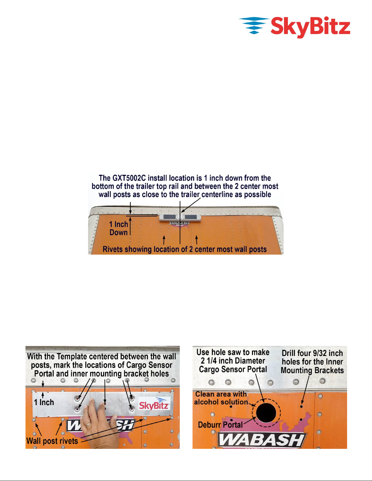
GXT5002C Mounting Location
The GXT5002C will be mounted to front wall of the trailer about one inch down from the bottom of the top rail
and centered between the wall posts nearest the trailer centerline. Please contact
CustomerCare@SkyBitz.com for questions on any issues with this mounting location for the GXT5002C.
Record Trailer ID & GXT5002C Serial Number
Begin by recording the GXT5002C serial number and the trailer ID number. Remove the serial number sticker
taped to the top of the GXT5002C and affix it to the trailer paperwork. Enter this information into the SkyBitz
Mobile APP or email the trailer ID and GXT5002C serial number to CustomerCare@SkyBitz.com.
GXT5002C Tracking System Sheet and Post Nose Trailer Installation
Use the GXT5002C Installation Template to mark the location of the cargo sensor portal and the four Internal
Mounting Bracket stud holes per the mounting location shown above. Use a hole saw to bore a 2.25 inch hole
for the cargo sensor portal. Deburr any sharp edges of the portal and clean the area around the portal with the
alcohol solution and clean rags. Drill the four 9/32 inch holes for the Internal Mounting Brackets.
SkyBitz CMANRAP027 GXT5002C Sheet & Post Nose Trailer Install Guide Rev C 12/20/2017 2
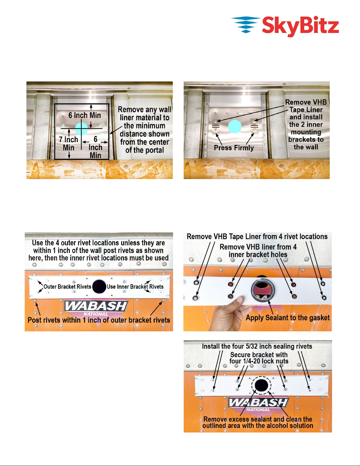
From inside the trailer, use a saw to remove any inner wall liner material that could interfere with the Cargo
Sensor Performance. This includes any inner wall liner material within six inches of the top and sides of the
center of the cargo sensor portal and any Inner Wall Liner material within seven inches below the center of the
cargo sensor portal. Remove the VHB tape liner from the two Internal Mounting Brackets and install them into
the 9/32 inch holes. Press firmly on the back of the brackets to bond the VHB tape to the trailer wall.
Outside the trailer, hold the External Mounting Bracket in place and determine which four of the eight rivet
locations will be used. The preferred rivet set is the four outer rivets. If the four outer rivets end up within an
inch of the wall post rivet centerline, then the inner rivet holes must be used. Once you have determined which
four rivet holes will be used, remove the liner from the VHB donuts on those four rivet hole locations. Remove
the VHB liner from the four Inner Mounting Bracket holes as well. Apply a continuous bead of silicone sealant
to the circular foam gasket on the GXT5002C External Mounting Bracket.
Align the External Mounting Bracket with the four
Internal Mounting Bracket studs and secure the
bracket to the trailer with the four 1/4-20 lock nuts.
Use a 5/32 inch drill bit to match drill the four
chosen rivet locations. Install the 5/32 inch rivets
into the four rivet locations. Completely remove any
excess silicone sealant from around the cargo
sensor portal, inside the trailer as well as on the
surface of the External mounting bracket. Use the
alcohol solution and clean rags to remove any
remaining sealant from the outlined area of the
External Mounting Bracket surface as shown.
 Loading...