

Telular CDMAFWT2004 User Manual

4/19/04 Part Number 56029901
Phonecell
®
SX5T CDMA2000
®
1X
Fixed Wireless Terminal
800/1900 MHZCDMA
U
SER MANUAL

Phonecell®SX5T CDMA ii User Manual
QUICK CONNECTION GUIDE
SX5 Fixed Wireless Terminal

Phonecell®SX5T CDMA iii User Manual
Before installing the Phonecell®SX5T, carefully remove the contents from the shipping carton
and check for evidence of shipping damage. If damage is found, contact your Authorized
Telular Distributor or shipping agent immediately.
SAFE OPERATION INSTRUCTIONS
IMPORTANT! Before installing or operating this product, read the SAFETY INFORMATION
section of this manual.
••
Install the unit indoors.
••
Install the unit on a hard, flat surface for proper ventilation.
••
Do not expose the unit to rain or moisture.
••
Do not place the unit on or close to sources of heat.
IMPORTANT NOTICES
TERMS AND CONDITIONS FOR USE OF PHONECELL®PRODUCTS ("Product")
These Terms and Conditions are a legal contract between you and Telular Corporation for the title to
and use of the Product. BY RETAINING AND USING THE PRODUCT AFTER RECEIPT OF IT,
YOU AGREE TO THE TERMS AND CONDITIONS INCLUDING WARRANTY DISCLAIMERS,
LIMITATIONS OF LIABILITY AND INDEMNIFICATION PROVISIONS BELOW. IF YOU DO NOT
AGREE TO THE TERMS AND CONDITIONS, DO NOT USE THE PRODUCT AND IMMEDIATELY
RETURN THE UNUSED PRODUCT FOR A COMPLETE REFUND. You agree to accept sole
responsibility for any misuse of the Product by you; and, in addition, any negligent or illegal act or
omission of your or your agents, contractors, servants, employees, or other users of the Product so
long as the Product was obtained from you, in the use and operation of the Product.
INDEMNIFICATION OF TELULAR CORPORATION ("TELULAR")
YOU SHALL INDEMNIFY, DEFEND AND HOLD HARMLESS TELULAR FOR ANY OF THE COST, INCLUDING REASONABLE ATTORNEYS' FEES, AND FROM CLAIMS ARISING OUT OF YOU, YOUR CLIENTS' OR OTHER THIRD PARTIES'
USE OR OPERATION OF THE PRODUCT: (i) FOR MISUSE OR IN A MANNER NOT CONTEMPLATED BY YOU AND
TELULAR OR INCONSISTENT WITH THE PROVISIONS OF THIS MANUAL; (ii) IN AN ILLEGAL MANNER OR AGAINST
PUBLIC POLICY; (iii) IN A MANNER SPECIFICALLY UNAUTHORIZED IN THIS MANUAL; (iv) IN A MANNER HARMFUL
OR DANGEROUS TO THIRD PARTIES; (v) FROM CLAIMS BY ANYONE RESPECTING PROBLEMS, ERRORS OR MISTAKES OF THE PRODUCT; OR (vi) COMBINATION OF THE PRODUCT WITH MATERIAL, MODIFICATION OF THE
PRODUCT OR USE OF THE PRODUCT IN AN ENVIRONMENT NOT PROVIDED, OR PERMITTED, BY TELULAR IN
WRITING. THE PARTIES SHALL GIVE EACH OTHER PROMPT NOTICE OF ANY SUCH COST OR CLAIMS AND COOPERATE, EACH WITH THE OTHER, TO EFFECTUATE THIS INDEMNIFICATION, DEFENSE AND HOLD HARMLESS.
PLEASE SEE THE IMPORTANT NOTICES SECTION OF THIS MANUAL FOR
IMPORTANT INFORMATION ON USE, WARRANTY AND INDEMNIFICATION
CONTENTS
Telular Corporation
Corporate Headquarters
647 North Lakeview Parkway
Vernon Hills, Illinois 60061, USA
Technical Support
Tel: 847-247-9400 • Fax: 847-247-0021
E-mail: support@telular.com • http://www.telular.com
Phonecell®SX5T CDMA FWT Spike Antenna
Part Number 56029901 ©2004 Telular Corporation, All Rights Reserved
Power Supply
AC Power Cord

Phonecell®SX5T CDMA iv User Manual
TABLE OF CONTENTS
QUICK CONNECTION GUIDE ......................................................................................ii
IMPORTANT NOTICES.................................................................................................iii
Technical Support ......................................................................................................iii
SETUP............................................................................................................................1
Emergency Batteries..................................................................................................1
SX5 Location and Installation ....................................................................................2
Wall Mounting.............................................................................................................2
Connect the SX5 to AC Power...................................................................................3
Attach a Telephone to the SX5 ..................................................................................3
GETTING TO KNOW YOUR SX5..................................................................................4
LED Status Indicators ................................................................................................4
Important Dial Tones ..................................................................................................5
CALL FUNCTIONS ........................................................................................................6
Making Calls...............................................................................................................6
Receiving Calls ..........................................................................................................6
Ending Calls ...............................................................................................................6
In-Call Features..........................................................................................................6
SX5 USER FEATURES..................................................................................................7
Messages (Voice Mail and Text Messages)...............................................................7
Audio Settings ............................................................................................................7
Dial Settings ...............................................................................................................7
Caller ID .....................................................................................................................8
Setting Time and Date ...............................................................................................8
Reset User Factory Defaults......................................................................................8
Dialing Prefix Setup ...................................................................................................9
DATA FEATURES ........................................................................................................10
Connecting SX5 a Computer ...................................................................................10
Configure PC for Circuit Switch Data.......................................................................10
Automatic Baud Rate Fallback Control....................................................................10
Digital Fax Setup ......................................................................................................11
Analog Modem Support............................................................................................11
SX5T CDMA FWT WITH FAX......................................................................................14
Set SX5 for Analog Fax ...........................................................................................14
Connect SX5 for Dual Jack Mode............................................................................14
Connect SX5 for Single Jack Mode .........................................................................14
Fax Timing Adjustments...........................................................................................14
Analog Fax Bypass ..................................................................................................15
SX5 TROUBLESHOOTING .........................................................................................15
CONFORMANCE STATEMENTS ................................................................................16
SAFETY INFORMATION .............................................................................................16
WARRANTY.................................................................................................................18
SETUP
Safe Operation Requirement
The Phonecell®SX5 must be either wall mounted or desk mounted and should not be operated
when any person is within 203 mm (8 inches) of the antenna.
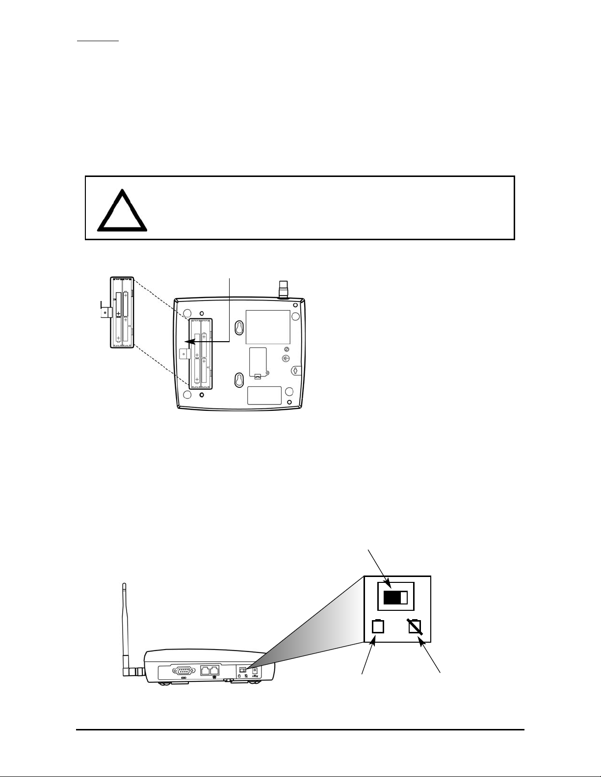
Emergency Batteries
Install Batteries
1. Remove the battery access door screw located on the bottom of the unit - see Figure 3.
2. Press the battery access door tabs and remove the battery access door.
3. Install 4 “AA” alkaline batteries (not supplied) - see Figure 3.
4. Reinstall the battery access door using the screw.
5. To test the batteries, turn the AC/Battery switch to battery operation. After the test, turn the
switch back to AC unless you want to continue to operate from battery power. - see Figure 4.
NOTE: The SX5 does not support rechargeable batteries.
Battery Operation
The unit will not automatically switch from AC to battery upon loss of AC power. The AC/Battery
switch must be changed manually - see Figure 4. Battery power will provide up to one hour of
standby and 30 minutes of talk time, depending on the SX5 model.
Phonecell®SX5T CDMA 1 User Manual
AC/Battery Switch
Figure 4 – SX5 AC/Battery switch.
Battery Position AC Position
WARNING!
Only “AA” alkaline batteries are to be used with the Phonecell®SX5.
Use of any other batteries may result in fire and/or other damage to the unit.
!
Battery
Access
Door
Battery Access
Door Screw
Figure 3 – SX5 battery installation.

Phonecell®SX5T CDMA 2 User Manual
SX5 Location and Installation
The SX5 comes with a standard spike antenna (TNC) - see Figure 5. For optimal signal
strength, choose a location that is above ground and as close to windows (or exterior walls) as
possible - see Figure 6. Cellular signal strength is displayed by the Received Signal Strength
Indicator (RSSI) LED on the unit - See the How to Use the LED Status Indicators section of this
manual.
1. Connect the antenna to the terminal - see Figure 5.
2. Finger-tighten the antenna. Do not over-tighten the antenna.
Wall Mounting
1. Mark two hole locations 98,5 mm (3-7/8 inches) vertically apart and drill two holes into the
wall.
2. Install the screws (not supplied) into the wall, leaving a gap (approximately 3 mm (1/8 inch))
between screw head and wall.
3. Align the mounting holes with the screws and mount the SX5 onto the screws - see Figures
7 and 8.
Figure 6 – Typical SX5 installation.
Wall Mount
Figure 5 –
SX5 antenna connection.
Spike
antenna
TNC Antenna
Connector
Table Mount
Figure 7 – SX5 mounting holes.
Figure 8 – Mount the SX5 onto the screws.
Mounting Holes
98,5 mm (3 7/8”)
Phonecell®SX5T CDMA 3 User Manual
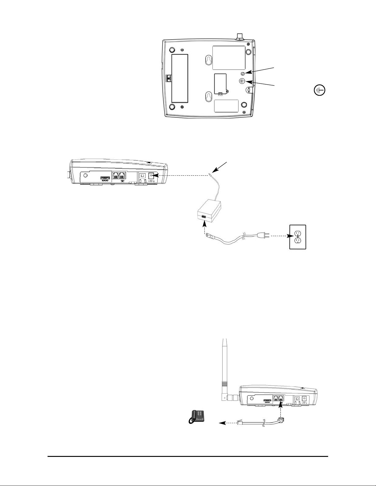
Connect the SX5 to AC Power
1. A protective earth (safety
ground) terminal (screw)
marked with a protective
earth symbol is provided
on the back of the SX5 see Figure 9a. Connect
this terminal to a good
earth ground (i.e., a cold
water pipe) by means of
an 18 gauge or heavier
insulated wire. The wire
insulation should be
green with a yellow stripe
to indicate that this is a
protective earth (safety
ground) connection.
2. Connect the barrel connector of the power supply to the AC power input receptacle of the
SX5 - see Figure 9b.
3. Plug the AC power cord into the power supply.
4. Plug the AC power cord into the AC Power outlet.
HINT: If there are no batteries in the SX5, it will only power on if the AC/Battery switch is in
the AC position - see Figure 4.
5. Check the cellular signal strength and move the unit until you achieve the best signal
possible - see the LED Status Indicators section of this manual.
Attach a Telephone to the SX5
1. Plug one end of a standard phone
cord into a phone- see Figure 10.
2. Connect the other end of the phone
cord to the telephone port on the side
of the SX5 (marked with a phone icon)
- see Figure 10.
Figure 9a –
Earth ground terminal screw.
Protective earth
(safety ground)
terminal screw
Protective earth
symbol
Figure 9b –
Connect the SX5 to AC Power.
AC Power
AC Power Input
AC Power Cord
Power
Supply
Barrel Connector
Figure 10 - Connect SX5 to Telephone.

Phonecell®SX5T CDMA 4 User Manual
GETTING TO KNOW YOUR SX5
LED Status Indicators
The LED indicators are activated when the SX5 is powered on. The following tables describe the
modes and operation of the indicators.
NOTE: If you are getting no service, contact your service provider for more information.
RSSI 3
RSSI 2
RSSI 1
Service Indicator
Hook Indicator
Message Indicator
Power/Battery
* Contact your service provider to verify that service has been activated.
Service Indicator
LED Color Activity Description
Green Continuous Full Service
Green Flashing Roaming
Red Continuous No Service*
Received Signal Strength Indicator (RSSI)
RSSI LED's Activity Cellular Signal Strength
Flashing Lowest
Continuous Poor
Flashing Fair
Continuous Good
Flashing Very Good
Continuous Best
RSSI 1
RSSI 2
RSSI 3
 Loading...