

Page 1
TEL-TRU MANUFACTURING COMPANY
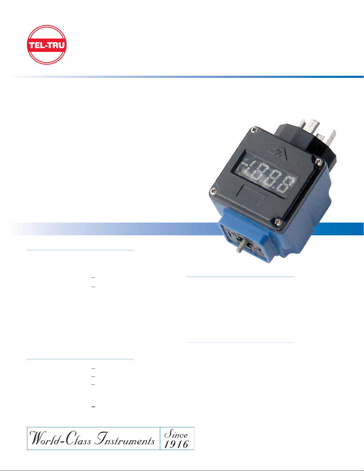
PTD-1 LOCAL READOUT DISPLAY
www.teltru.com
The PTD-1 loop powered display is designed for direct readout in milli-Amps VC, percent of
full scale, or engineering units. The display is configurable from -1999 to +1999, and may be
used on most instruments with 4 to 20mA output and a DIN 43650 electrical connection.
➤ Reliable in harsh environments and high vibration applications
• High-impact ABS housing
• Fully gasketed
• NEMA 4X
• Surface mount electronics
➤ Easy field setup
➤ NIST traceable calibration certificate available
when display is factory installed on models that use
DIN 43650 Aconn. and 4-20mAelectronics
➤ ELECTRICAL
Excitation: 12-36 Vdc
Voltage Drop: 2.5 Vdc Max
Zero Balance: <
±1% FSO
FSO Setting: <
±1% FSO
Display: LED (LCD Available)
Update Rate: < 100 mS
Insulation Resistance: 1000 MΩ at 50 Vdc
Reverse Polarity: Protected
EMI/RFI: Internal Filtering
Short Circuit Protected: Up t o 4 0 Vd c
➤ PERFORMANCE
Accuracy: < ±0.05% FSO (BFSL, RSS)
Repeatability: < ±0.05% FSO
Temperature Effects: <
±0.5% FSO over comp range
(combined effects of zero and
FSO with reference at 70º F)
Long Term Stability: <
±0.05% FSO per year
➤ MECHANICAL
Materials: High impact ABS plastic
neoprene gasket
Mates With: DIN 43650 electrical connector
Dimensions: See outline drawing
Weight: Approximately 3 oz.
➤ ENVIRONMENTAL
Compensated Temp Range: 0 to 170ºF
Operating Temp Range: 0 to 200ºF
Storage Temp Range: -20 to 200ºF
Specifications
Page 2
Tel-Tru Manufacturing Company
408 St. Paul St., Rochester, New York 14605 USA
Phone: 585.232.1440 • 800.232.5335 • Fax: 585.232.3857 • E-mail: [email protected] • Web: www.teltru.com
PTD-1 LOCAL READOUT DISPLAY
NEMA 4X Loop powered, Customer configurable
PTD1SHT05
➤ INSTALLATION
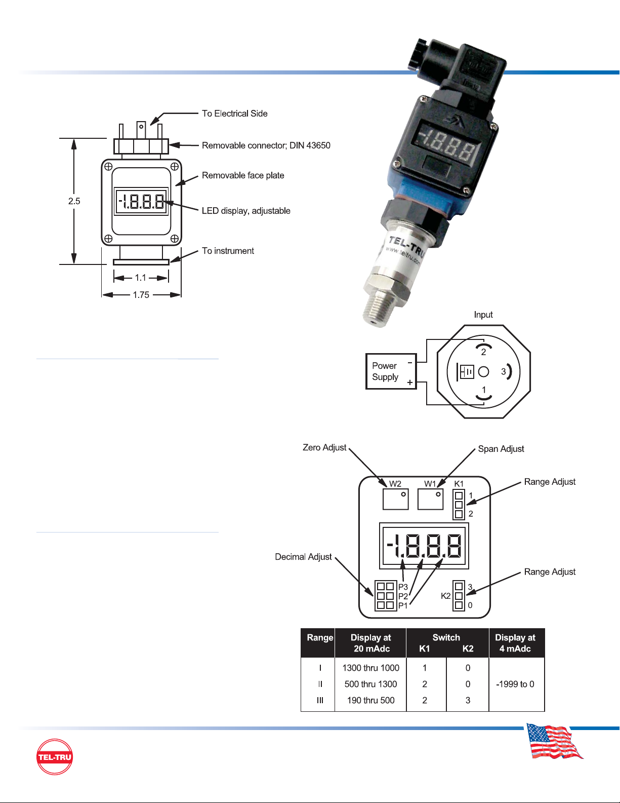
1. Unscrew Hex nut and remove
connector.
2. Install indicator on instrument.
Please be certain wiring is +
in : Pin 1, return/signal : Pin 2.
3. Tighten mounting screw located
in center of indicator. Re-install
connector and Hex nut.
4. Install mating DIN connector.
➤ CALIBRATION
1. Remove face plate (4 screws).
2. Determine position for switch K1 and K2 and
short appropriate pins.
3. Install display on instrument.
4. Apply input voltage to Pin 1 of removable connector
(12-36 Vdc).
5. Apply the zero pressure, adjust zero pot to desired
zero reading.
6. Apply full scale pressure, adjust span pot to desired
span reading.
7. Install face plate.
MADE IN USA
 Loading...