

Page 1
RF Unit USER AND INSTALLATION MANUAL
CLASSIFICATION:
PRODUCT:
CODE:
VERSION:
RF Unit
D168X01_DDS09
01
REVISION:
04
DATE:
09/03/10
General information Internal document
DOCUMENT MAINTENANCE
THIS DOCUMENT HAS 17 PAGES
EDIT. DATE AUTHOR DESCRIPTION
1.0 27/12/07 José Roman RF Unit User and Installation Manual.
1.1 09/10/08 Javier Córdova General revision.
1.2 04/11/08 Javier Córdova Correction of subclauses 6.2, 6.3.
1.3 16/06/09 José Román Add FCC RF Exposure Requirements:
1.4 09/03/10 A. Narvaiza Change logo & change in 1 (409-430 MHz).
DOCUMENT APPROVAL
ACTIVITY NAME DATE SIGNATURE
Prepared
Revised
Project Manager
Approved
R&D Director
01.01.00/1 Rev.1
Page 2

RF Unit USER AND
Code: D168X01_DDS09
INSTALLATION
Disclaimer
Although every reasonable effort has been made to ensure the accuracy of the information contained herein
and any other referred document, this should not be construed as a commitment on the part of Teltronic S.A.
Unipersonal, and the liability of Teltronic S.A. Unipersonal for any errors and omissions shall be limited to the
correction of such errors and omissions. Teltronic S.A. Unipersonal welcomes any comment as a way to
improve any delivered documentation.
The information contained herein has been prepared for the use of appropriately trained personnel, and it is
intended for the purpose of the agreement under which the information is submitted. Any party using or relying
upon this information assumes full responsibility for such use and in no event shall Teltronic S.A. Unipersonal
be liable to anyone for especial, collateral, incidental, or consequential damages in connection with or arising
out of the use of this information.
The information or statements given in these documents regarding the suitability, capacity or performance of
the mentioned hardware or software products cannot be considered binding but shall be defined in the
agreement made between Teltronic S.A. Unipersonal and the customer.
Teltronic S.A. Unipersonal reserves the right to revise these documents and to make changes to its content at
any time, without prior notification.
Copyrights
No part of the information contained herein and the other referred documents may be copied, distributed or
transmitted by any means to any other party without prior written permission of Teltronic S.A. Unipersonal. The
distribution of this document may be also covered by NDA (non-disclosure agreement) between Teltronic S.A.
Unipersonal and the receiver.
Please also note that part of these contents even may be covered by patent rights.
This document, the referred documents and the described product are considered protected by copyright
according to the applicable laws.
Teltronic and the Teltronic logo are registered trademarks of Teltronic S.A. Unipersonal.
Copyright © Teltronic S.A. Unipersonal. All rights reserved.
MANUAL
Date: 09/03/10 Page: 2 of 16
01.01.00/1 Rev.1
Page 3

CONTENTS:
1.
INTRODUCTION.........................................................................................................4
2.
UNPACKING AND CHECKING..................................................................................5
3.
PREVIOUS CONSIDERATIONS.................................................................................5
4.
INFORMATION ON SAFETY AND ELECTROMAGNETIC COMPATIBILITY............5
5.
EQUIPMENT DESCRIPTION......................................................................................7
5.1.
FRONT VIEW.......................................................................................................7
5.2.
REAR VIEW .........................................................................................................8
5.3.
MODULES............................................................................................................9
6.
INSTALLATION GUIDE............................................................................................12
RF Unit USER AND
Code: D168X01_DDS09
INSTALLATION
MANUAL
Date: 09/03/10 Page: 3 of 16
7.
8.
6.1.
LOCATION.........................................................................................................12
6.2.
POWER SUPPLY CONNECTION......................................................................12
6.3.
ANTENNA CONNECTION .................................................................................13
6.4.
SWITCHING ON THE RF UNIT..........................................................................13
CONFIGURATION....................................................................................................14
INCIDENTS...............................................................................................................14
8.1.
ALARMS ............................................................................................................14
01.01.00/1 Rev.1
Page 4
RF Unit USER AND
!
Code: D168X01_DDS09
INSTALLATION
MANUAL
Date: 09/03/10 Page: 4 of 16
1. INTRODUCTION
The RF Unit is the RF transceiver of Teltronic P25 systems, with a transmitter
output power of 100W. Therefore, this is a mandatory module in the infrastructure P25
network. It is manufactured following a robust mechanical modular design which allows
simple and economic maintenance.
The RF Unit is available in the following frequency bands:
380 - 400 MHz
409 - 430 MHz
450 - 470 MHz
764 - 806 MHz
806 - 870 MHz
The modules that form the RF Unit are:
RPS (Repeater Power Supply P25)
RPA P25 (Repeater Power Amplifier P25)
RTX P25 (Repeater Transmitter P25)
RRX P25(Repeater Receiver P25)
BSYNC (RF Unit Synchronism) - OPTIONAL
RCPU P25(Repeater Control Processing Unit P25)
The proper operation of any electronic device depends on its correct use. It is
therefore recommended to follow the instructions in this manual.
CAUTION: Switch the RF Unit off before inserting/removing any of its modules.
01.01.00/1 Rev.1
Page 5
RF Unit USER AND
Code: D168X01_DDS09
INSTALLATION
MANUAL
Date: 09/03/10 Page: 5 of 16
2. UNPACKING AND CHECKING
The following elements are supplied in the box:
RF Unit
50 / 20W load termination
Power Supply Cable
Maintenance Cable
Two Ethernet Cables
The equipment is supplied with all the modules already assembled in the rack. The
modules in the basic configuration are: Power Supply module (RPS), Power Amplifier
(RPA P25), Transmitter (RTX P25), Receiver (RRX P25) and Control (RCPU P25).
Synchronism module (BSYNC) is necessary for testing purposes.
IMPORTANT: if any of these elements is missing or damaged, contact your dealer
and / or installer.
3. PREVIOUS CONSIDERATIONS
This manual contains information on instructions for installation, maintenance and
use. Read the following pages before using this equipment.
Do not switch on the RF Unit without having previously connected the TX antenna
and the 50Ω load to the TNC connector. The equipment may be seriously damaged. It is
important to use an antenna adjusted to the RF Unit transmitter frequency band.
4. INFORMATION ON SAFETY AND ELECTROMAGNETIC COMPATIBILITY
The equipment has been designed to fulfil the applicable compliance regulations.
The equipment complies with Part 15 of the FCC Title 47 of the Code of Federal
Regulations. Operation is subject to the condition that this device does not cause harmful
interference.
The equipment complies with the applicable Part 90 of the FCC Title 47 of the
Code of Federal Regulations.
01.01.00/1 Rev.1
Page 6

RF Unit USER AND
!
Code: D168X01_DDS09
INSTALLATION
FCC RF Exposure Requirements:
CAUTION:
The antenna(s) used for this transmitter must not be co-located or operating in conjunction
with any other antenna or transmitter. This device is approved with emissions having a
source-based time-averaging duty factor not exceeding 50%.
Failure to observe these restrictions will result in exceeding the FCC RF exposure limits.
In any case, take the following points into consideration:
Most electronic equipments are susceptible to electromagnetic interference if
they are not duly protected. If the RF Unit is placed near unprotected
MANUAL
Date: 09/03/10 Page: 6 of 16
electronic devices, they may malfunction.
The RF Unit must not transmit without its antenna connected or without the
50Ω load in the TNC connector.
When installing the antenna, follow the guidelines for exposure of the human
body to high and low frequency electromagnetic fields. Follow the supplier’s /
manufacturer’s instructions.
Burns may be suffered if the antenna connector output of the power module
(RPA P25) is touched by bare skin when the RF Unit is transmitting with the
antenna disconnected.
Take care when handling the RF Unit. It has sharp edges, which may cut if
handled incorrectly.
Maintenance and repair of these repeaters must be carried out by qualified
personnel only.
Connect the RF Unit chassis to the earth intake in the cabinet where it is to
be installed.
Switch off the RF Unit before inserting/removing any of its modules
01.01.00/1 Rev.1
Page 7
RF Unit USER AND
INSTALLATION
5. EQUIPMENT DESCRIPTION
5.1.
FRONT VIEW
1.- RPS (Repeater Power Supply).
2.- RPA P25 (Repeater Power Amplifier).
3.- RTX P25 (Repeater Transmitter).
4.- RRX P25 (Repeater Receiver).
5.- BSYNC (RF Unit Synchronism) - OPTIONAL
6.- RCPU P25 (Repeater Control Processing Unit).
7.- Power Supply switch.
1 2
7
MANUAL
Code: D168X01_DDS09
Date: 09/03/10 Page: 7 of 16
3
4 5 6
01.01.00/1 Rev.1
Page 8
24
23
20
19
17
16
15
14
10
12
13
8
5.2.
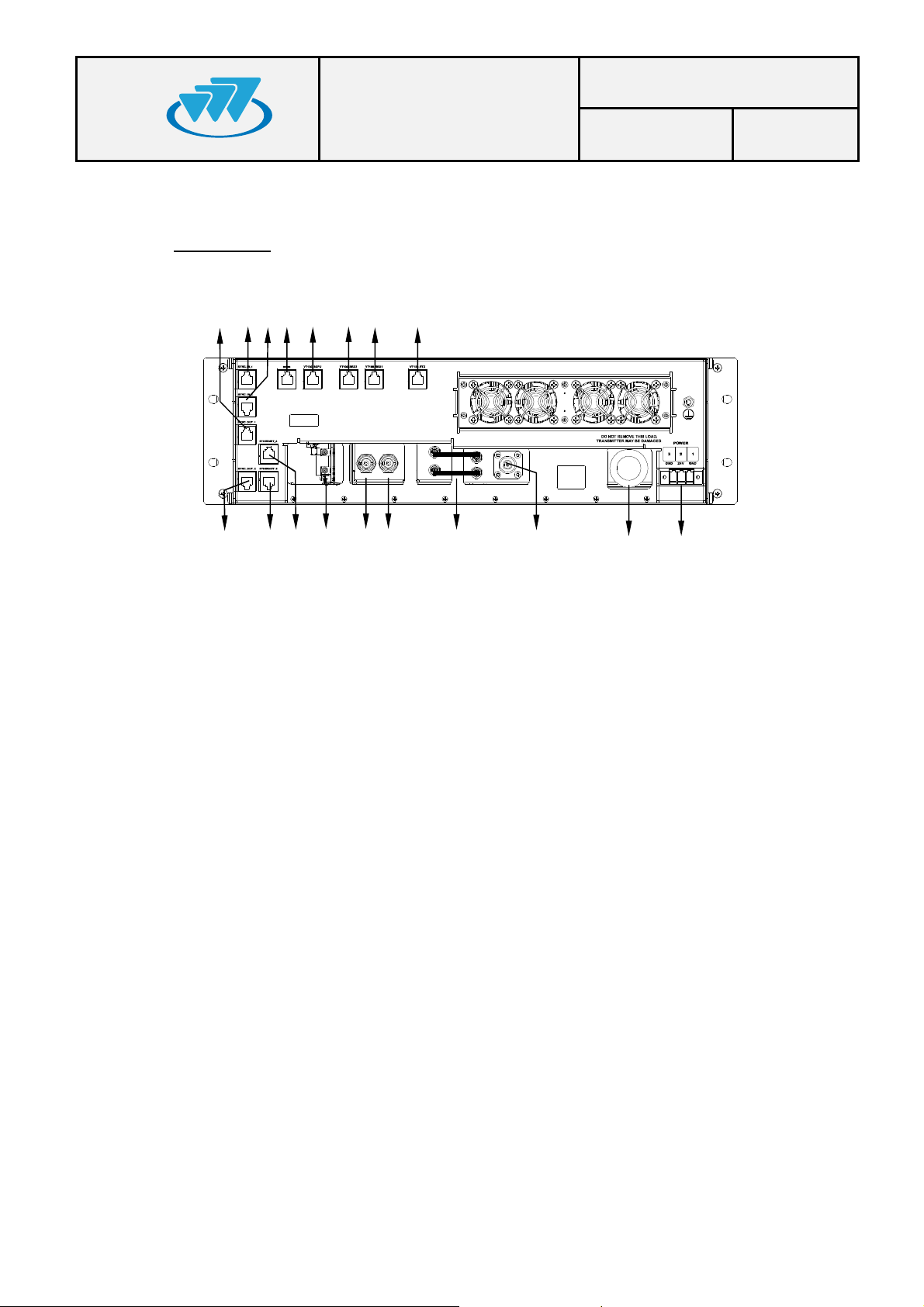
REAR VIEW
RF Unit USER AND
INSTALLATION
21
8.- Power Supply Connector.
9.- TX Antenna Connector (type N).
10.- RF cables between RTX P25 and RPA P25.
11.- RX Antenna Connector (type BNC).
12.- RX Diversity Antenna Connector (not used).
13.- BSYNC Connectors (not used).
14.- Ethernet Connector “ETHERNET_A”.
15.- Ethernet Connector “ETHERNET_B”.
16.- Synchronism Output Connector “SYNC_OUT_2”.
17.- Synchronism Output Connector “SYNC_OUT_1”.
18.- Synchronism Input Connector “SYNC_IN_1”.
19.- Synchronism Input Connector “SYNC_IN_2”.
20.- Bus BSR maintenance connector.
21.- RCPU P25 maintenance connector (VT-100).
22.- RRX2 maintenance connector (Not used).
23.- RRX P25 maintenance connector (VT-100).
24.- RTX P25 maintenance connector (VT-100).
25.- 50 / 20W load termination (TNC connector).
MANUAL
9
Code: D168X01_DDS09
Date: 09/03/10 Page: 8 of 16
25
01.01.00/1 Rev.1
Page 9
RF Unit USER AND
Code: D168X01_DDS09
INSTALLATION
5.3.
MODULES
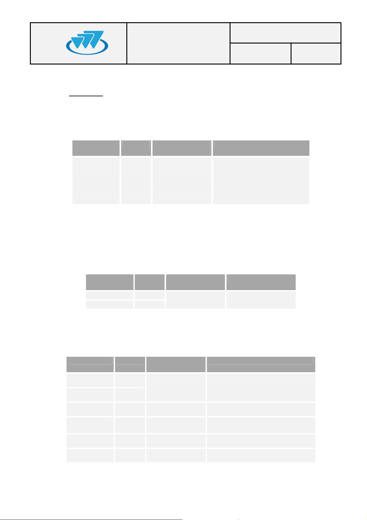
1.- RPS (REPEATER POWER SUPPLY)
LEDs to indicate module status.
LED TYPE NORMAL
SUPPLY Green On There are 26.4V at the RPS
26.4V Green On There are 26.4V at the RPS
13.2V Green On There are 13.2V at the RPS
Power Supply switch (Ref. 7): ON/OFF switch to connect to and disconnect from the
RF Unit
2.- RPA P25 (REPEATER POWER AMPLIFIER)
LEDs to indicate module status.
LED TYPE NORMAL
ON Green On Power supply correct
TX POWER Green On Module transmitting
3.- RTX P25 (REPEATER TRANSMITTER)
LEDs to indicate module status.
LED TYPE NORMAL
ON Green On Power supply correct
MANUAL
STATUS
STATUS
STATUS
Date: 09/03/10 Page: 9 of 16
FUNCTIÓN
input
output
output
FUNCTIÓN
FUNCTIÓN
REF. ERROR Red Off Failure in the 10 MHz reference
INT. ERROR Red Off Internal failure
BUS ERROR Red Off Communication failure with the
RCPU P25 module
RPA ERROR Red Off RPA P25 failure
RPW ERROR Red Off Reflected power failure
01.01.00/1 Rev.1
Page 10
RF Unit USER AND
Code: D168X01_DDS09
INSTALLATION
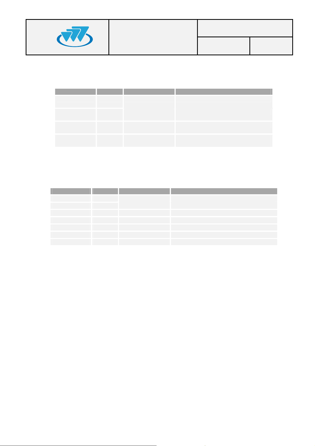
4.- RRX P25 (REPEATER RECEIVER)
LEDs to indicate module status.
LED TYPE NORMAL STATUS
ON Green On Power supply correct
REF. ERROR Red Off Failure in the 10 MHz reference
INT. ERROR Red Off Internal failure
BUS ERROR Red Off Communication failure with the RCPU
5.- SLOT OPTION: BSYNC (RF Unit SYNCHRONISM)
LEDs to indicate the status of option BSYNC.
LED TYPE NORMAL STATUS
ON Green On Power supply correct
REF. ERROR Red Off Failure in the 10 MHz reference
WARM UP Red Off Oscillator in warming up phase
TIME GPS Green Flashing There is NMEA signal from GPS
PPS GPS Green Flashing There is PPS signal from GPS
TIME LOCAL Green Flashing There is NMEA local signal (without GPS)
PPS LOCAL Green Flashing There is PPS local signal (without GPS)
NOTE: this slot is not used in the RF Unit basic configuration.
MANUAL
Date: 09/03/10 Page: 10 of 16
FUNCTIÓN
P25 module
FUNCTIÓN
01.01.00/1 Rev.1
Page 11
RF Unit USER AND
Code: D168X01_DDS09
INSTALLATION
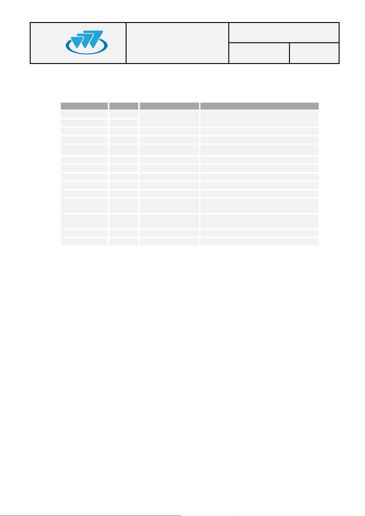
6.- RCPU P25 (REPEATER CONTROL)
LEDs to indicate the module status.
LED TYPE NORMAL STATUS
ON Green On Power supply correct
REF. ERROR Red Off Failure in the 10 MHz reference
INT. ERROR Red Off Internal failure
BUS ERROR Red Off RF Unit bus failure
DIV ERROR Red Off Diversity failure
LSC ERROR Red Off Communication failure with the LSC
AUX Green Off Not used
MCCH Green Off / On Main carrier indicator
RF RX Green Flickering APCO P25 information received
RF TX Green On APCO P25 information transmission
ETH LINK1 Yellow On Link between the local network switch and
ETH LINK2 Yellow Off Link between the local network switch and
ETH RX Green Flashing Reception of an Ethernet packet
ETH TX Green Flashing Transmission of an Ethernet packet
MANUAL
Date: 09/03/10 Page: 11 of 16
FUNCTIÓN
the RCPU P25 module in Ethernet port 1
the RCPU P25 module in Ethernet port 1
01.01.00/1 Rev.1
Page 12

RF Unit USER AND
Code: D168X01_DDS09
INSTALLATION
MANUAL
Date: 09/03/10 Page: 12 of 16
6. INSTALLATION GUIDE
The following recommendations must be followed closely before starting up the RF
Unit module.
6.1.
LOCATION
The RF Unit has been designed in the standard format of 19” / 3 units high and it
must be installed in cabinets with this format.
The RF Unit site must be permanent, well-ventilated and without vibrations.
6.2.
POWER SUPPLY CONNECTION
DC power supply: check that the power supply source and/or the battery to be
used meets the voltage and current requirements necessary to supply the equipment:
Nominal voltage: 26.4VDC (range: from 21.12 to 31.68 VDC).
Minimum source current: 20 A.
There is a power control circuit in the RPS P25 module in order to avoid an
over-current condition.
If lead batteries are used, they are to be placed as far from the RF Unit as
possible to prevent corrosion in the repeater due to battery vapours. They
should be situated in a well-ventilated place.
Use the power supply connector provided (D013000) to connect the RF Unit to
the power supply source. Use a cable with 2.5 mm2 minimum diameter (or
AWG-12). Ensure that the connection is made with the correct polarity.
Ensure that the earth connection is made. Make this connection with a cable of
maximum diameter and minimum length.
NEVER use a gas or electricity conduit as an earth.
01.01.00/1 Rev.1
Page 13

6.3.
ANTENNA CONNECTION
Choose the most adaptable antenna for the installation. The antenna must
have an impedance of 50 ohms to the equipment transmission frequency.
Install the antenna in accordance with the manufacturer’s instructions.
Use a coaxial cable, avoiding as much as possible large cable lengths. Cable
impedance is 50 ohms.
Measure the ROE of the installation. Never accept a ROE greater than 2.
If a duplexer, a combiner or a band pass filter is required, adjust them to the
working frequency before starting up.
RF Unit USER AND
INSTALLATION
MANUAL
Code: D168X01_DDS09
Date: 09/03/10 Page: 13 of 16
6.4.
SWITCHING ON THE RF Unit
Check the connections between the modules.
Check that the power supply source is connected correctly.
Check that the RF SMB cables are connected correctly (see Rear View
diagram Ref. 10).
Check the connections of the antennas in the RPA P25 and RRX P25 modules.
Check the 50Ω load is connected to the rear TNC connector in the RPA P25.
Check that the RPS P25 module LED SUPPLY is on.
Activate the power on switch on the RPS P25 module.
Check that the 26.4V LED and 13.2V LED on the RPS P25 module are on and
check that the LEDS “ON” are switched on in the other modules.
Wait for the RF Unit to start up.
Note: See subclause 5.3 for more information on references for the different
modules and LEDs.
01.01.00/1 Rev.1
Page 14
RF Unit USER AND
!
Code: D168X01_DDS09
INSTALLATION
MANUAL
Date: 09/03/10 Page: 14 of 16
7. CONFIGURATION
A RF Unit is configured via an NMS (Network Management System). To configure
the RF Unit, consult the NMS manual.
8. INCIDENTS
The repeater must be repaired by authorized technical personnel only. If a RF
Unit failure occurs, the entire RF Unit must be replaced. If transmitter module
is damaged and there is not an entire RF Unit available to replace, set RTX
P25 and RPA P25 modules previously calibrated jointly. In last case and if is
not possible to carry out one of the two previous options, replace one of these two
modules and make the gain calibration again.
If an error or alarm occurs in the RF Unit, this is indicated in the corresponding
LED for each one of the modules. The following list shows the possible failures and their
solutions.
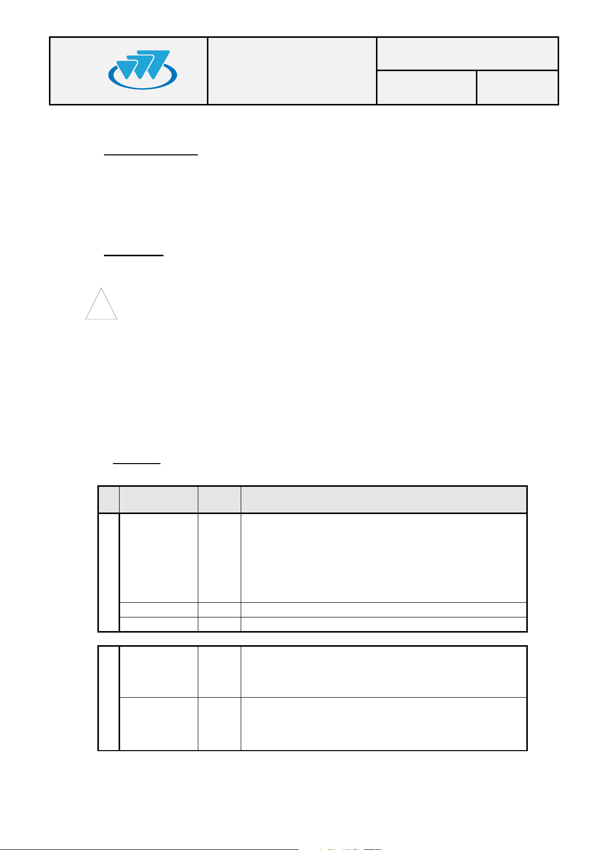
8.1.
ALARMS
Led
RPS
RPA P25
Status
indication
POWER SUPPLY FAILURE. CHECK THAT THE
SOURCE AND THE POWER SUPPLY CABLE
SUPPLY OFF
26.4V OFF Power supply failure. Contact Technical services.
13.2V OFF Power supply failure. Contact Technical services.
ON OFF
TX POWER OFF
ARE CORRECTLY CONNECTED. CHECK THE
INTERNAL FUSE OF THE RPS. CONTACT
TECHNICAL SERVICES IF UNSOLVED.
POWER SUPPLY FAILURE. CONTACT
TECHNICAL SERVICES.
No power transmission in the antenna. Wait for RF Unit
to be started up. Check other LED indications. Contact
Technical Services if unsolved.
Failure / Solution
01.01.00/1 Rev.1
Page 15
RF Unit USER AND
Code: D168X01_DDS09
INSTALLATION
MANUAL
Date: 09/03/10 Page: 15 of 16
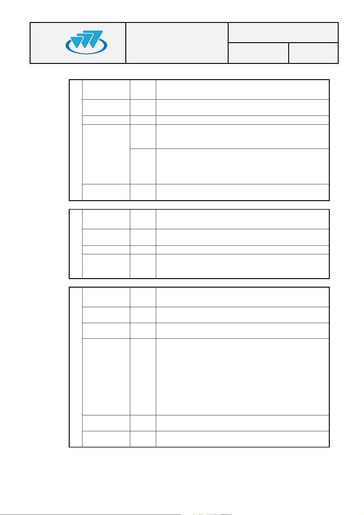
ON OFF
REF. ERROR ON
INT. ERROR ON Internal failure. Contact Technical services.
BUS ERROR ON
RTX P25
RPA P25
ERROR
RPW ERROR ON
ON OFF
REF. ERROR ON
INT. ERROR ON Internal failure. Contact Technical services.
RRX P25
BUS ERROR ON
ON
Failure in the 10MHz reference. Contact Technical
services.
Communication failure with the RCPU P25 module.
Check that all the modules are correctly installed.
Contact Technical services if still unsolved.
Reflected power alarm. Check that the antenna is
properly installed. Contact Technical services.
Failure in the 10MHz reference. Contact Technical
services.
Communication failure with the RCPU P25 module.
Check that all the modules are correctly installed.
Contact Technical Services if still unsolved.
INTERNAL POWER SUPPLY FAILURE.
CONTACT TECHNICAL SERVICES.
FAILURE IN THE RPA P25 MODULES. CHECK
THAT THE RF SMB CABLES (REF. 10) ARE
PROPERLY CONNECTED. CONTACT
TECHNICAL SERVICES IF STILL UNSOLVED.
INTERNAL POWER SUPPLY FAILURE.
CONTACT TECHNICAL SERVICES.
ON OFF
REF. ERROR ON
TIME GPS ON
BSYNC
PPS GPS OFF
TIME LOCAL OFF
PPS LOCAL OFF
Failure in the 10MHz reference. Contact Technical
services.
If GPS is activated, there is failure in the data frame.
Contact Technical Services.
If GPS is activated, there is failure in the PPS signal of
the GPS:
Contact technical services if still unsolved.
If GPS is not activated, there is failure in the local
reference data frame. Contact Technical Services.
If GPS is not activated, there is failure in the local PPS
signal. Contact Technical Services.
INTERNAL POWER SUPPLY FAILURE.
CONTACT TECHNICAL SERVICES.
- check that the starting up period has been exceeded
(about 10 minutes after switching on)
- check the GPS antenna connection.
- check the correct positioning of the GPS antenna, in
accordance with the manufacturer’s instructions.
01.01.00/1 Rev.1
Page 16
RF Unit USER AND
Code: D168X01_DDS09
INSTALLATION
MANUAL
Date: 09/03/10 Page: 16 of 16
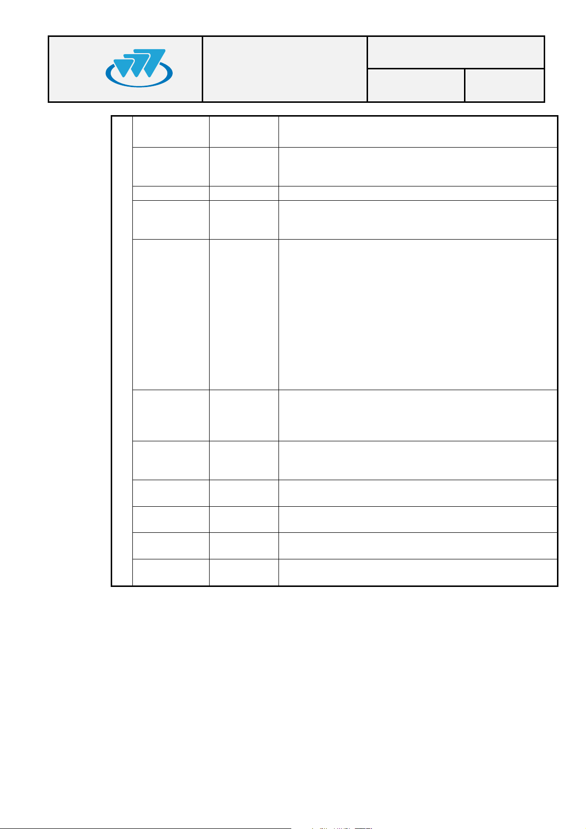
ON OFF
REF ERROR ON
INT ERROR ON Internal failure. Contact Technical Services.
BUS ERROR ON
DIV ERROR ON
RCPU
LSC ERROR ON
RF RX
ETH LINK1 OFF
ETH LINK2 OFF
ETH RX OFF
ETH TX OFF
Continuous
ON
INTERNAL POWER SUPPLY FAILURE.
CONTACT TECHNICAL SERVICES.
Failure in the 10MHz reference. Check that the BSYNC
module is installed or that the SYNC IN cable is correctly
connected. Contact Technical services if still unsolved.
Communication failure by the RF Unit bus. Check that all
the modules are correctly installed. Contact Technical
services if still unsolved.
Error in diversity: occurs when the difference in received
power between received paths exceeds a level (20 dBs
by default) for a consecutive number of receptions.
These receptions on the received paths which do not
have sufficient power are not counted.
This alarm does not disappear until there are no
receptions with the sufficient power, and until the
difference of received power between received paths
does not exceed the level previously mentioned.
Check diversity configuration in the MSC.
Check that the reception antennas are correctly
installed. Contact Technical services if still unsolved.
Communication failure with the LSC. Check the Ethernet
connections.
Check that the LSC is working correctly. Contact
Technical Services if still unsolved.
Interference detection.
Check the installation. Check that the work frequencies
are correct.
Failure in Ethernet link 1.
Check Ethernet connection 1 and the Switch A.
Failure in Ethernet link 2.
Check Ethernet connection 2 and the Switch B.
Packets are not received by Ethernet.
Check the Ethernet connections.
Packets are not sent by Ethernet.
Check the Ethernet connections.
01.01.00/1 Rev.1
 Loading...