

VRT014
User‘s guide V0.8
Thank you for purchasing our product. We hope this user-friendly device will be
helpful in realising your ideas and bringing comfort to your life. Please take few
minutes to read this manual before starting to work with VRT014. This would make
the installation and use of device easier.
Address: Saltoniškių g. 10c, Vilnius LT-08105,
Phone: (370-5) 2127472,
Fax: (370-5) 276 1380, Email: info@teltonika.lt

i
i
i
I N T R O D U C T I O N
VRT014 is a very simple device which can be used for authorised door access,
controlling gates, switching of remote equipments, car parking systems, activate/deactivate
alarm systems and etc. Basically this device can be used in places which require ON/OFF
switching action. This ON/OFF functionality of VRT014 can be achieved by making a phone
call.
Whenever a person calls VRT014, the device compares the phone number of incoming
call with the numbers stored in the memory of device. If a match is found, it means the
caller is an authorized person. Due to this VRT014 will turn ON its’ output, in short, sending
a signal to activate the connected device. VRT014 does not have any answer function;
therefore, the calling person does not have to pay any charges for the call.
Up to 500 different numbers can be stored in the memory of device.
In additional you can turn ON the relay by using an external switch input. When a
logically low signal is given to this input the output will be turned ON.
VRT014's
VRT014 can be configured in two ways,
a) By sending an SMS
b) By connecting the device to a PC using COM port interface and the VRT014
configuration software.
output turns OFF always after relay‘s timeout. The timeout is programmable
P A C K A G E C O N T E N T S
Cardboard box.
Device VRT014.
CD (including the required information and software.)
Configuration cable for connection between the device and personal computer
GSM antenna.
Quick start guide
Note: The package does not include any SIM card. The SIM card must be acquired from
your GSM service supplier.
If any part from the package is missing, please contact your local dealer, seller or the
business representative.
T E C H N I C A L S P E C I F I C A T I O N S
Power Supply Voltage 9…15 VDC
Average Power consumption 2 W
Operating Temperature -20°C...+40°C
Maximum Switching Current 5 A
Maximum Switching Voltage 240VAC, 30VDC
Relay programmable timeout 0,5...65 sec
Dual Band GSM modem TM1 900/1800MHz
Dimensions 90mmx58mmx53mm
2

i
Picture 1. External view and measurements of the device
Dimension: 90 x 58 x 53 (mm)
D E S C R I P T I O N O F T H E D E V I C E A N D P R I N C I P L E S O F
F U N C T I O N I N G
The device VRT014 consists of a microcontroller and GSM modem.
The microcontroller receives and processes signals.
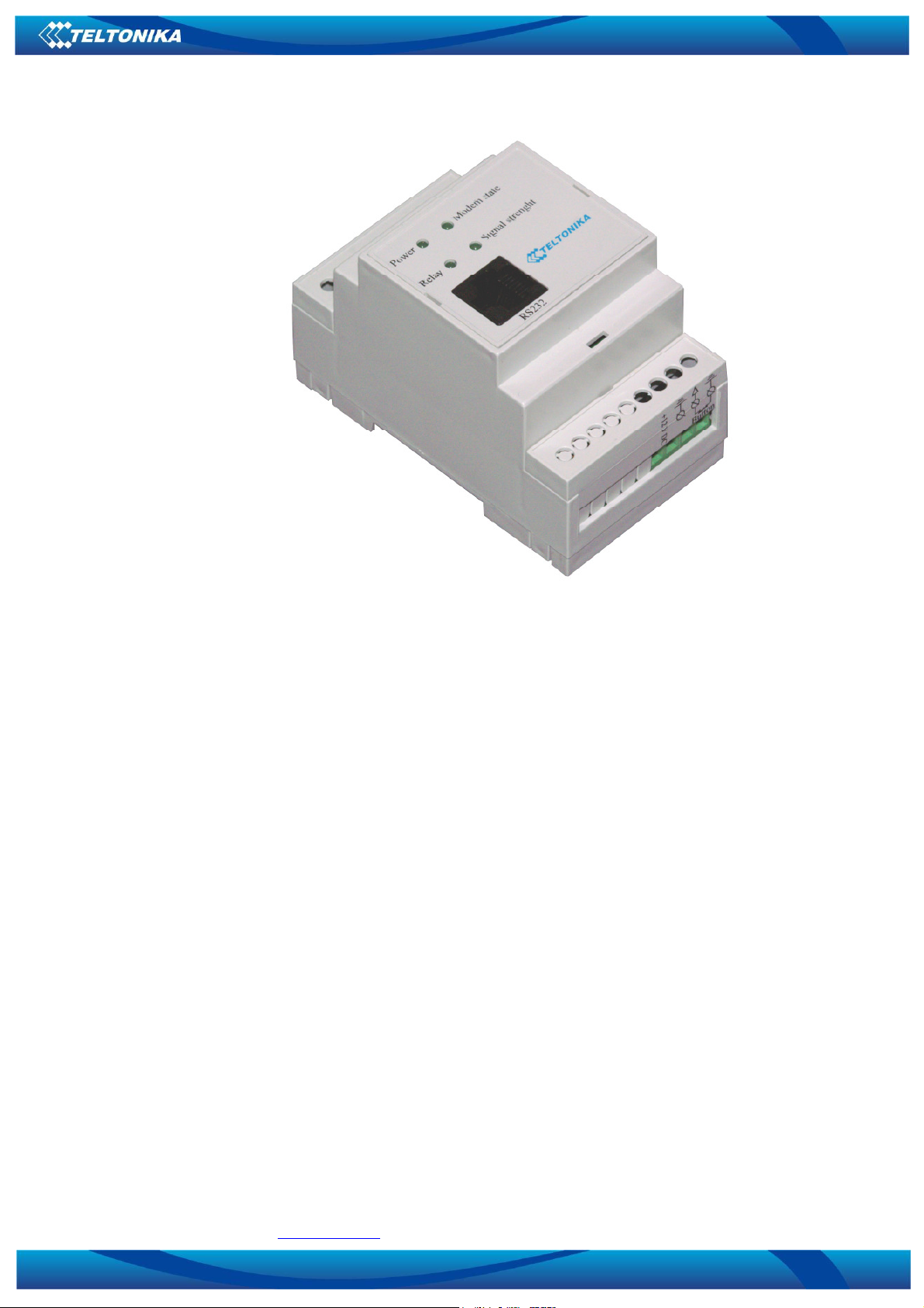
There are 4 light diodes on the external board of the device as shown in picture 2.
Picture 2. Device VRT014
The light diode Power is directly connected to the Power supply chain of the
microcontroller.
The light diode Modem State is connected to the GSM modem and its status depends on
the operation logic of the GSM modem and its specifications (The diode may have no
flashing).
The light diodes Relay and Signal Strength are connected to the microcontroller and
reflect the status of the device.
The light diode Relay reflects the signal status of activating the internal relay. When the
relay is activated, the light diode is also on.
The light diode Signal Strength reflects the Power of the signal received via the GSM
modem.
When the Power is supplied, the light diodes Relay and Signal Strength reflect the start
of activating the programme and its various stages. If the connection is correct, the light
diodes are flashing alternately as specified in the table below, and when the operation status
is activated, they are operating in accordance to their main functions.
3
 Loading...