

Page 1

TSP Edge
User’s Manual
40-400-00065, Rev. E
Page 2

Note
This manual covers Model TSP-EDGE-01, hardware modules TSP-DT1E1-01, TSP-8PFXO-01, TSP8POTS-01 and software modules TSP-PRI, TSP-2PRI, TSP-ATS.
Copyright Notice
Copyright © 2002-2004 Teltone Corporation
All Rights Reserved
Trademarks
Teltone is a registered trademark of Teltone Corporation.
TSP is a trademark of Teltone Corporation.
Windows is a registered trademark of Microsoft Corporation.
Other company and product names may be trademarks or
registered trademarks of their respective owners.
Teltone Corporation
Bothell, Washington, USA
Customer Service: 425-951-3388
Technical Support: 425-951-3390
Fax: 425-487-2288
Email: [email protected]
Website: www.teltone.com
40-400-00065, Rev. E
ii
Page 3

Table of Contents
Overview..............................................................................................................1
Standard Features.....................................................................................1
Typical Applications................................................................................2
End-to-End Calls ..............................................................................2
Call Originate and Call Terminate....................................................4
Bulk Call Generation ........................................................................5
Installation Tests...............................................................................5
Telephony Interfaces................................................................................5
Digital Interface Modules .................................................................6
Analog Interface Modules ................................................................7
Advanced Software Modules...................................................................8
TSP-PRI............................................................................................8
TSP-2PRI..........................................................................................9
TSP-ATS...........................................................................................9
License Codes ..........................................................................................9
Setup ....................................................................................................................9
System Requirements...............................................................................9
Power ................................................................................................9
PC .....................................................................................................10
Checking Your Edge Package .................................................................10
Optional Hardware............................................................................10
Optional Software Modules..............................................................11
Installing Hardware Modules...................................................................11
Communications Connections .................................................................12
Console Port......................................................................................13
10/100 LAN (Ethernet) Connection .................................................13
Powering Up the Edge .............................................................................13
Installing Edge Software..........................................................................14
Programming the Edge ........................................................................................14
Basics .......................................................................................................14
Main Window ..........................................................................................15
Menus ...............................................................................................15
Tree Display......................................................................................16
Information Section ..........................................................................16
Icons..................................................................................................16
Control Set Enables ..........................................................................17
Units.........................................................................................................18
Unit Configuration............................................................................18
Viewing Unit Information ................................................................22
Unit Configuration Summary ...........................................................23
Module Configuration ......................................................................23
Module Configuration Summary......................................................33
Templates.................................................................................................33
Type Tab...........................................................................................34
40-400-00065, Rev. E iii
Page 4

Timings Tab......................................................................................36
Signaling Tab....................................................................................38
Template Configuration Summary ...................................................39
Control Sets..............................................................................................40
Control Set Type Field......................................................................40
Template Field..................................................................................42
Channel Assignments .......................................................................43
Start and Stop....................................................................................44
End-to-End Example ........................................................................45
Control Set Configuration Summary................................................47
Options.....................................................................................................48
Alerts Tab .........................................................................................48
Upgrades Tab....................................................................................48
Unassigned Channels Tab.................................................................50
Executing and Viewing Simulations....................................................................51
Executing a Simulation............................................................................51
Event Log.................................................................................................52
Diagnostics...............................................................................................55
Trace ........................................................................................................56
Test Automation Interface ...................................................................................58
Basic Operation........................................................................................58
Communicating with Edge Configuration Software Using DDE.....59
Communicating with Edge Configuration Software Using TCP .....60
Commands ...............................................................................................61
GETMESSAGES..............................................................................61
GETSTATUS ...................................................................................62
INITIALIZE .....................................................................................63
LISTCARDS.....................................................................................64
LISTCHANNELS.............................................................................65
LISTFILES .......................................................................................66
LISTTASKS .....................................................................................67
LISTUNITS ......................................................................................68
LOADFILE.......................................................................................69
RUNTASK .......................................................................................70
SETDIAGNOSTIC...........................................................................71
SETMONITOR.................................................................................72
SETPRIEVENTS..............................................................................73
Warning Messages...................................................................................74
Events.......................................................................................................76
Event Number Reference Tables .............................................................77
Standard Messages............................................................................77
PRI Send Messages...........................................................................79
PRI RCV Messages ..........................................................................80
N_STAT_IN Causes.........................................................................81
CAUSE_IND ....................................................................................83
SIGNAL_IND...................................................................................84
40-400-00065, Rev. E
iv
Page 5

PROGRESS_IND .............................................................................85
NOTIFY_IND...................................................................................85
INFO_RQ_IND ................................................................................86
FEATURE_IND ...............................................................................86
Primary Rate ISDN Software Modules (TSP-PRI and TSP-2PRI) .....................87
T1 PRI (North American Standards) .......................................................88
T1 Tab...............................................................................................88
PRI Tab.............................................................................................90
Channels Tab ....................................................................................91
E1 PRI (EURO-ISDN).............................................................................92
E1 Tab...............................................................................................93
PRI Tab.............................................................................................95
Channels Tab ....................................................................................96
Advanced Test Scripting Software Module (TSP-ATS) .....................................97
Using ScriptBuilder .................................................................................98
Move, Cut, Copy, Paste, Delete and Undo .......................................100
Navigation Window..........................................................................100
Commands ...............................................................................................100
Conditionals/Timers/Events .............................................................101
Line States ........................................................................................103
Tones/Audio .....................................................................................105
Establishing Audio Connections between Channels................................109
Assigning a Script to a Control Set..........................................................110
Sample Scripts .........................................................................................111
Troubleshooting ...................................................................................................112
Warranty and Service...........................................................................................117
Warranty Information ..............................................................................117
Return Procedures....................................................................................117
Technical Assistance................................................................................117
Maintenance.............................................................................................117
Cleaning............................................................................................117
Servicing ...........................................................................................117
Ordering Information...........................................................................................118
Hardware Chassis.....................................................................................118
Optional Hardware Modules....................................................................118
Optional Software Modules .....................................................................118
Accessories ..............................................................................................118
Extended Warranties................................................................................118
Revision History ..................................................................................................119
Specifications.......................................................................................................122
Appendices...........................................................................................................125
Call Timings and Process Flowcharts......................................................125
Call Timings .....................................................................................125
Call Process Flowcharts....................................................................128
Connector and Cable Pin-outs .................................................................152
Console Port......................................................................................152
40-400-00065, Rev. E v
Page 6

10/100 LAN (Network) PORT .........................................................153
T1/E1 Ports .......................................................................................153
POTS Ports .......................................................................................154
References............................................................................................................156
Glossary ...............................................................................................................158
Index ....................................................................................................................165
40-400-00065, Rev. E
vi
Page 7

List of Figures
Figure 1. Edge - Front..........................................................................................1
Figure 2. Single T1/E1 End-to-End .....................................................................3
Figure 3. Dual T1/E1 End-to-End........................................................................3
Figure 4. Analog LS to T1/E1 End-to-End..........................................................4
Figure 5. Analog LS to Analog LS End-to-End ..................................................4
Figure 6. Analog Loop Start, Call Originate and Call Terminate........................5
Figure 7. Edge - Back ..........................................................................................5
Figure 8. Dual T1/E1 Module..............................................................................6
Figure 9. 8 Channel POTS FXS Module .............................................................7
Figure 10. 8 Channel POTS FXO Module...........................................................7
Figure 11. Serial and Ethernet Connections on the Edge Back Panel .................13
Figure 12. Configuration Software New Project .................................................15
Figure 13. Main Window.....................................................................................16
Figure 14. Unit Screen .........................................................................................18
Figure 15. Module Matrix Wizard.......................................................................20
Figure 16. T1 Card Mode T1 Tab........................................................................24
Figure 17. E1 Card Mode E1 Tab........................................................................26
Figure 18. POTS FXS Card Type........................................................................28
Figure 19. POTS FXO Card Type .......................................................................29
Figure 20. Channel Identification ........................................................................30
Figure 21. Channel Configuration Wizard...........................................................32
Figure 22. Template Type Tab.............................................................................34
Figure 23.Template Timings Tab ........................................................................37
Figure 24.Template Signaling Tab ......................................................................38
Figure 25. Control Set..........................................................................................40
Figure 26. Channel Assignments (Analog)..........................................................43
Figure 27. Channel Assignments (T1 Channels) .................................................44
Figure 28. End-to-End Control Set Example.......................................................46
Figure 29. Connecting Channels..........................................................................46
Figure 30. Alerts Tab ...........................................................................................48
Figure 31. Upgrades Tab......................................................................................49
Figure 32. Setting the Default Idle State for Unassigned Channels ....................50
Figure 33. Control Set Information......................................................................51
Figure 34. Call Status...........................................................................................52
Figure 35. Events View on Event Log.................................................................53
Figure 36. Calls View on Event Log ...................................................................54
Figure 37. Select Diagnostic Channels Screen ....................................................55
Figure 38. Diagnostics Window ..........................................................................55
Figure 39. Trace Screen .......................................................................................56
Figure 40. T1-PRI Card Mode T1 Tab ................................................................88
Figure 41. T1-PRI Card Mode PRI Tab...............................................................90
Figure 42. T1-PRI Card Mode Channels Tab......................................................91
Figure 43. E1-PRI Card Mode E1 Tab ................................................................93
Figure 44. E1-PRI Card Mode PRI Tab...............................................................95
40-400-00065, Rev. E vii
Page 8

Figure 45. E1-PRI Card Mode Channels Tab......................................................96
Figure 46. Script Example Steps..........................................................................97
Figure 47. ScriptBuilder.......................................................................................99
Figure 48. Detecting DTMF Sequence ................................................................106
Figure 49. Control Set Dialog Box with a Script Assigned.................................110
Figure 50. Console Port Pin-out ..........................................................................152
Figure 51. Serial Cable RJ11 to RJ11..................................................................152
Figure 52. Serial Cable Adapters.........................................................................152
Figure 53. Network Port Pin-out..........................................................................153
Figure 54. Ethernet Cross-Over Cable.................................................................153
Figure 55. T1/E1 Module Pin-out........................................................................153
Figure 56. T1/E1 Cable........................................................................................154
Figure 57. 8 Channel POTS FXO Module Pin-out..............................................154
Figure 58. POTS FXS Module Pin-out................................................................154
Figure 59. POTS Y-Cable....................................................................................155
40-400-00065, Rev. E
viii
Page 9
IMPORTANT USER SAFETY INSTRUCTIONS
When using this product, basic safety precautions, including the following, should always be followed to reduce the risk of fire,
electric shock, and injury to persons.
1. Read and understand all instructions.
2. Follow all warnings and instructions marked on the product.
3. The product should be operated only from the type of power source indicated on the marking label. If you are not sure of the
type of power supply, consult your dealer or local power company. The product is designed for indoor use only.
4. To reduce the risk of electric shock, do not disassemble the product, but take it to qualified service personnel when service or
repair work is required. Opening or removing covers may expose you to dangerous voltages or other risks. Incorrect reassembly
can cause electric shock when the appliance is subsequently used.
5. If the product does not operate normally by following the operating instructions, or if the product has been dropped or the
cabinet has been damaged, or if the product exhibits a distinct change in performance, refer servicing to qualified service
personnel.
6. If the product is used in a manner other than specified in this manual, the protection provided by the product may be impaired.
7. For the purpose of removing power from the product, the power input connector is the main power disconnect point. Pull the
power cord away from the connector to ensure power disconnect.
8. Adequate air flow must be maintained in order for the product to operate correctly. Do not wrap the product in blankets, paper,
or other material that may impede ventilation.
40-400-00065, Rev. E ix
Page 10

x
U.S. REGULATORY COMPLIANCE
FCC Part 15 Class A Notice: This equipment has been tested and found to comply with the limits for a Class A digital device,
pursuant to part 15 of the FCC Rules. These limits are designed to provide reasonable protection against harmful interference when
the equipment is operated in a commercial environment. This equipment generates, uses, and can radiate radio frequency energy
and, if not installed and used in accordance with the instruction manual, may cause harmful interference to radio communications.
Operation of this equipment in a residential area is likely to cause harmful interference in which case the user will be required to
correct the interference at his own expense.
The Installation Category (OVERVOLTAGE CATEGORY) for this device is II and it is designed to be safe under POLLUTION
DEGREE 2, per IEC 1010-1: 1990 specifications.
The following only applies to the TSP-8PFXO-01 module:
FCC Part 68 Notice: To comply with FCC Part 68 regulations, the following requirements must be met:
1. If the telephone company requests information on the equipment connected to their lines, please tell them:
a. the telephone number the equipment is connected to;
b. this equipment operates on standard RJ11 phone jacks;
c. the FCC registration number;
d. the ringer equivalence number (REN). The REN shows how many devices, such as phones, modems, etc. can be
connected to your line. In most areas, there cannot be more than five devices (i.e., a REN of five) on a phone line. If the
REN is exceeded, then your phone may not ring properly.
NOTE: Items C and D above are found on the label on any Teltone equipment connected to your telephone line.
2. These devices must not be installed on coin-operated telephone lines or party lines.
3. Repair work on this device must be done by Teltone Corporation.
4. If any trouble is experienced with this equipment, the telephone company may request that the customer disconnect the
registered equipment from the telephone line to determine if the registered equipment is malfunctioning and if the registered
equipment is malfunctioning, the use of such equipment shall be discontinued until the problem has been corrected.
The following only applies to the TSP-8PFXO-01 module:
CANADIAN REGULATORY COMPLIANCE
Notice: This equipment meets the applicable Industry Canada Terminal Equipment Technical Specifications. This is confirmed by
the registration number. The Industry Canada label or the abbreviation, IC, before the registration number signifies that registration
was performed based on a Declaration of Conformity indicating that Industry Canada technical specifications were met. It does not
imply that Industry Canada approved the equipment. Industry Canada does not guarantee the equipment will operate to the user's
satisfaction. Before installing this equipment, users should ensure that it is permissible to connect it to the facilities of the local
telecommunications company. The equipment must also be installed using an acceptable method of connection. In some cases, the
company’s inside wiring associated with a single line individual service may be extended by means of a certified connector
assembly (telephone extension cord). The customer should be aware that compliance with the above conditions may not prevent
degradation of service in some situations.
Repairs to certified equipment should be made by Teltone Corporation. Any repairs or alterations made by the user to this
equipment, or equipment malfunctions, may give the telecommunications company cause to request the user to disconnect the
equipment. Users should ensure for their own protection that the electrical ground connections of the power utility, telephone lines,
and internal metallic water pipe system, if present, are connected together. This precaution may be particularly important in rural
areas.
Caution: Users should not attempt to make such connections themselves, but should contact the appropriate electric inspection
authority, or electrician, as appropriate. The Ringer Equivalence Number (REN) assigned to each terminal device provides an
indication of the maximum number of terminal devices to be connected to a telephone interface without overloading the interface.
The termination on an interface may consist of any combination of devices subject only to the requirement that the sum of the REN
of all devices does not exceed five (5) in most, but not all cases. Check with your local exchange carrier for the REN limit in your
service area. The REN assigned to each device is located on the equipment label.
COMPLIANCE NOTICE: This digital apparatus does not exceed the Class A limits for Radio Noise Emissions set out in the
equipment standard ICES-003 for digital apparatus.
AVIS DE CONFORMATION: Le présent appareil numérique n’émet pas de bruits radioélectriques dépassant les limites applicables
aux appareils numériques de la class A prescrites dans le Règlement sur le brouillage radioélectriques édicté par le ministère des
Communications du Canada.
40-400-00065, Rev. E
Page 11
OVERVIEW
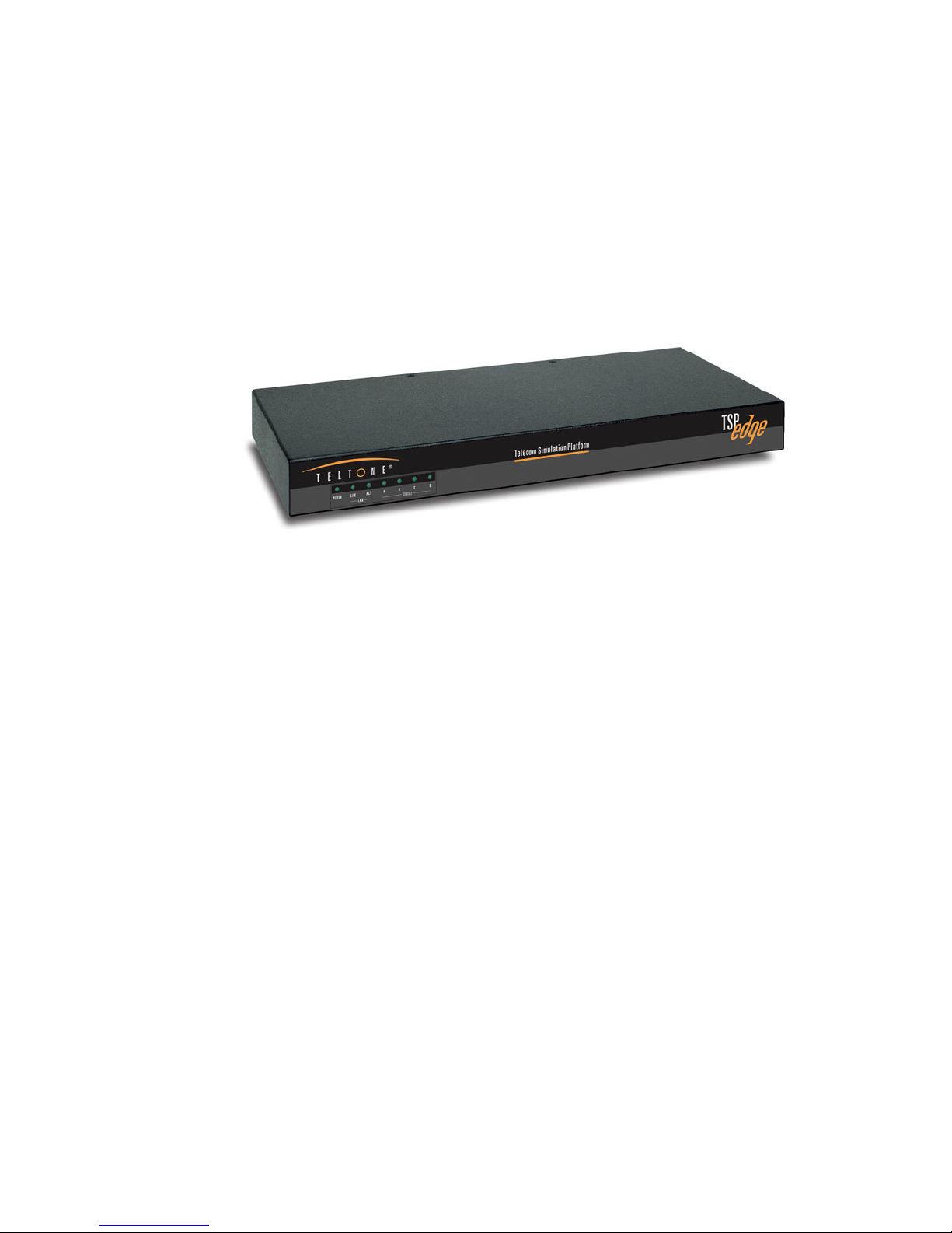
The Teltone TSP Edge is a combined hardware and software platform used to
simulate connections to different telephony interfaces. These include T1, E1, analog
POTS FXS, and analog POTS FXO. An RS-232 port and an Ethernet port are
provided to configure and control the Edge.
Telecom Simulation Platform
TSP Edge
Standard Features
• Base unit for configuring with optional hardware plug-in modules
• Upgradeable software and hardware modular design
• Analog POTS and T1/E1 simulation in the same system
• Operates under Windows 95/98/2000/XP or Windows NT
• Programming and control can be done with either the serial or Ethernet
connection
• Status display provides current state for each channel (on/off-hook, ringing,
etc)
• Supports three call types
o Originate – calls placed by the Edge to a connected device
o Terminate – calls placed into the Edge by a connected device
o End-to-End – calls placed through the Edge by one device to another
• Call progress and DTMF signaling
Figure 1. Edge - Front
• Event logging of
o On/off-hook
o Ringing
40-400-00065, Rev. E 1
Page 12

TSP Edge User’s Manual
o Time to answer
o Call duration
o Errors such as T1/E1 loss of sync
o Date/time of each event
• Programmable call parameters
o Analog channel types: Loop Start FXS and FXO
o T1 channel type (robbed bit signaling): Loop Start, Ground Start,
Immediate Dial, Wink Start, Delay Dial
o E1 channel signaling including: CAS Q.421 with DTMF Variation,
Loop Start, Ground Start, Wink, Immediate Dial, Delay Dial
o CAMA or Tie Trunk operation
o Programmable T1 and E1 signaling bit states for A, B, C & D bits
o T1/E1 Clear channel “nailed up” 64 KB/s connection
o Call Timing: Call Duration, Guard Time, Far-end Disconnect Time,
Delay Before Audio Message
o Dial String: ANI/DNIS Transmit Digits –40 Digits,
Phone Number –40 Digits
o Dial Tone: Enable, Delay Before, Length
o Ringback: Enable, Duration
• Bulk call generation
• Diagnostics with ability to place channels in different signaling states and
shows the signaling bit states on T1/E1
• Trace for detailed call progress of a channel
• Ability to control multiple Edge units with a single computer via the Ethernet
connection
Typical Applications
The Edge is configurable for three basic types of calls: End-to-End, Call Originate,
and Call Terminate. End-to-End calls are similar to calls placed through any switch;
calls are originated on one end and are terminated on the other end. However, in some
applications, you may want to simulate incoming traffic to a connected device; these
calls are originated from within the Edge. You may also want to monitor outgoing
traffic from a connected device, these calls are Terminated into the Edge.
End-to-End Calls
End-to-End calls are ones where one channel is connected to another. They are
initiated by an external device connected to the Edge, attempting to make a
40-400-00065, Rev. E
2
Page 13
TSP Edge User’s Manual
connection to another external device. For example, calling from one modem to
another on a pair of POTS connections, or from a POTS connection to a T1 modem
bank for V.90 modem testing. A T1/E1 Clear Channel application is where a single
channel operates as a 64 KB/s pipe, with no framing or control bits in the data stream.
The channel is cross-connected to another T1/E1 Clear Channel via the Control Set.
Dialed, Channel Bank, DS0 to DS0 (for Clear Channel operation only) and Switch
Emulation are the types of End-to-End Control Sets used by the Edge.
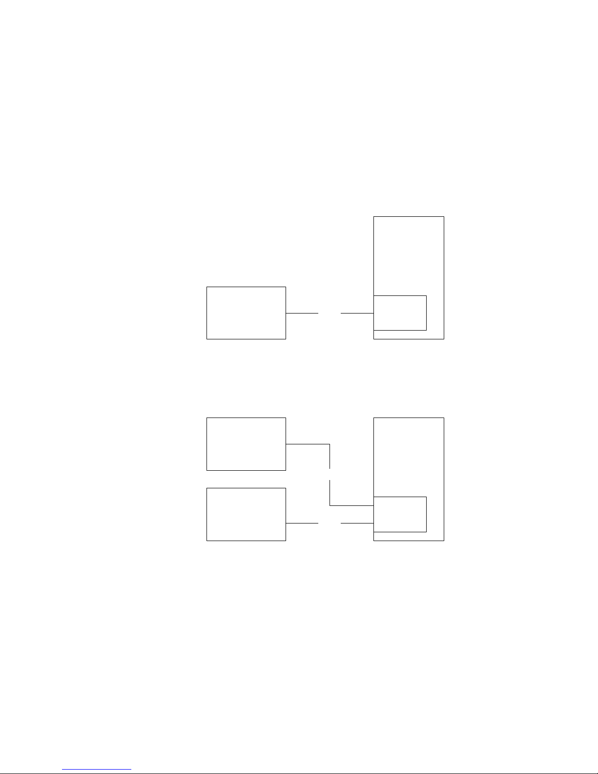
The Edge cross connects a channel on the T1/E1 to another channel on the same
T1/E1 (see Figure 2).
TSP Edge
Equipment under
Test
T1/E1
Single or
Dual T1/E1
Module
Figure 2. Single T1/E1 End-to-End
The Edge cross connects a channel on the first T1/E1 to any channel on the second
T1/E1 (see Figure 3).
Equipment under
Test
Equipment under
Test
T1/E1
T1/E1
TSP Edge
Single or
Dual T1/E1
Module
Figure 3. Dual T1/E1 End-to-End
40-400-00065, Rev. E
3
Page 14
TSP Edge User’s Manual
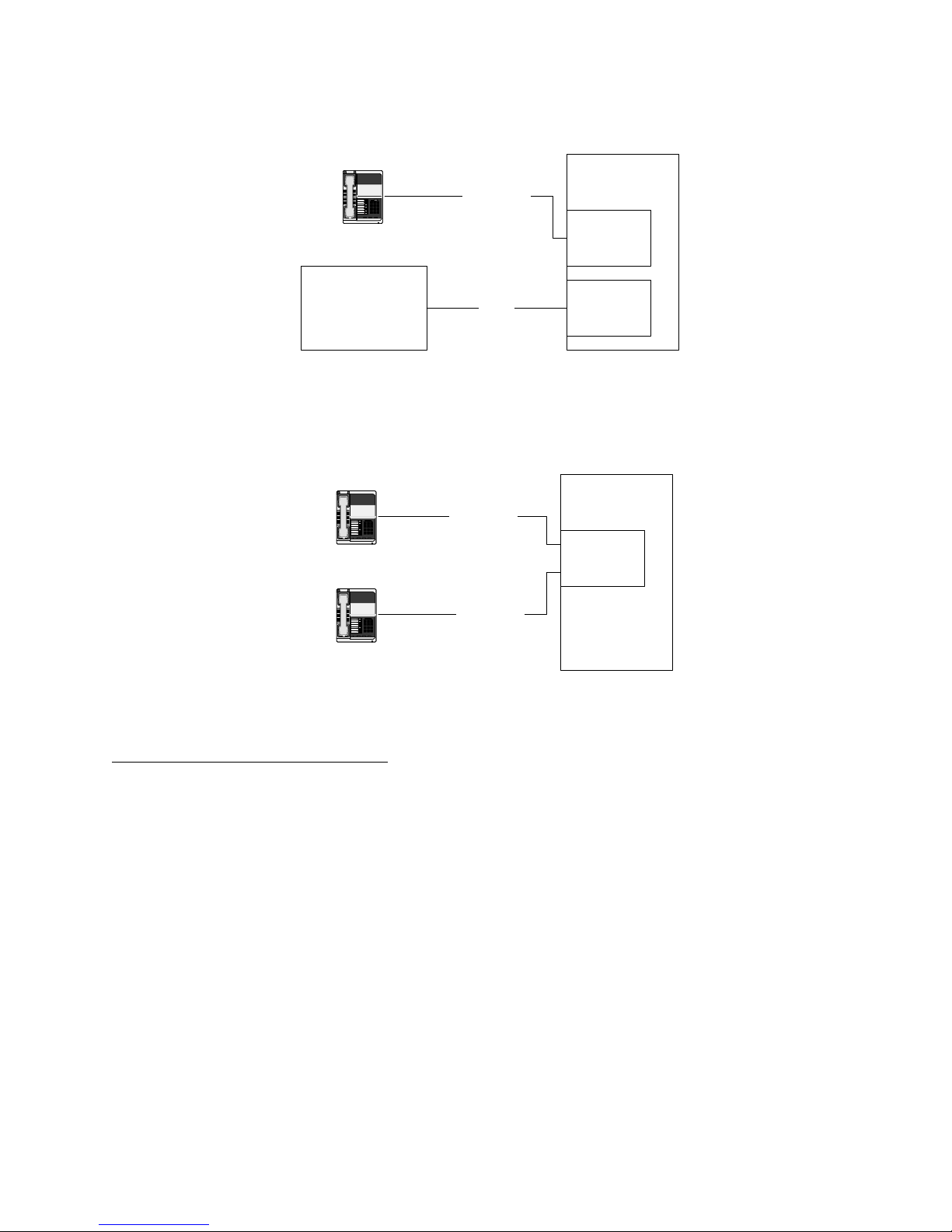
The Edge connects an Analog Loop Start channel to a T1/E1 channel (see Figure 4).
TSP Edge
123
456
789
8#
*
Term Set
2-wire Loop
4 or 8
Channel
POTS
Module
Equipment under
Test
T1/E1
Single or
Dual T1/E1
Module
Figure 4. Analog LS to T1/E1 End-to-End
The Edge connects an Analog Loop Start channel to another Analog Loop Start
channel (see Figure 5).
TSP Edge
123
456
789
8#
*
Term Set
123
456
789
8#
*
2-wire Loop
4 or 8
Channel
POTS
Module
2-wire Loop
Term Set
Figure 5. Analog LS to Analog LS End-to-End
Call Originate and Call Terminate
The Edge generates calls to the equipment under test in Call Originate mode. Call
Terminate mode is where the Edge receives calls from the equipment under test. In
both cases, the Edge will count the calls, and display the calls as completed,
unanswered, or busy in the event log. Once the calls are established; a WAV file can
be programmed to play to indicate that a call has taken place.
With Call Originate mode, the Edge generates calls on the channels of a T1/E1 line to
the equipment under test. With a Dual T1/E1 module, the calls can be generated on
both T1/E1s simultaneously. Call Terminate mode is where the Edge receives calls
from the equipment under test on the channels of the T1/E1 lines (see Figure 3).
For the POTS channels, the Edge generates calls to term set in Call Originate mode.
Call Terminate mode is where the Edge receives calls from the term set (see Figure
6).
40-400-00065, Rev. E
4
Page 15
Figure 6. Analog Loop Start, Call Originate and Call Terminate
Bulk Call Generation
Call Originate mode can be used for Bulk Call Generation. Bulk Call Generation are
calls that originate within the Edge, simulating call traffic, terminating at an external
device, often with some audio file playback when the external device answers. This
can be used to “stress test” the equipment under test.
123
456
789
8#
*
Term Set
2-wire Loop
TSP Edge User’s Manual
TSP Edge
4 or 8
Channel
POTS
Module
Installation Tests
The Edge can emulate the PSTN and be terminated to a PBX via a T1/E1 circuit or
multiple POTS connections. This allows for testing PBX programming and
functionality before live traffic is cut over to it.
Telephony Interfaces
The Edge has a modular design (see Figure 7) and the following hardware options:
• Dual T1/E1 module
• 8 Channel POTS FXS module
• 8 Channel POTS FXO module
• Single T1/E1 module (discontinued)
• 4 Channel POTS module (discontinued)
40-400-00065, Rev. E
Figure 7. Edge - Back
5
Page 16
TSP Edge User’s Manual
Digital Interface Modules
Dual T1/E1 Module
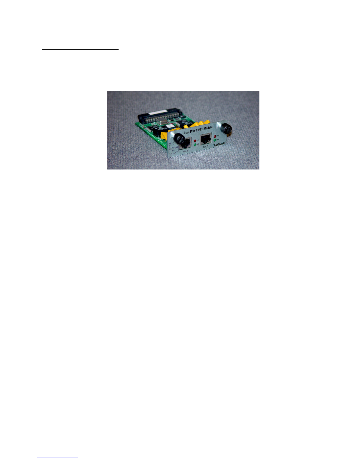
The Dual T1/E1 interface module (see Figure 8) supports T1, E1, and PRI
configurations.
LINK This LED indicator shows that the T1/E1 link is active
ERR This LED indicator shows that an error has occurred
Figure 8. Dual T1/E1 Module
Single T1/E1 Module (Discontinued)
The Single T1/E1 module is identical to the Dual T1/E1 except there is only one port.
40-400-00065, Rev. E
6
Page 17
TSP Edge User’s Manual
Analog Interface Modules
8 Channel POTS FXS Module
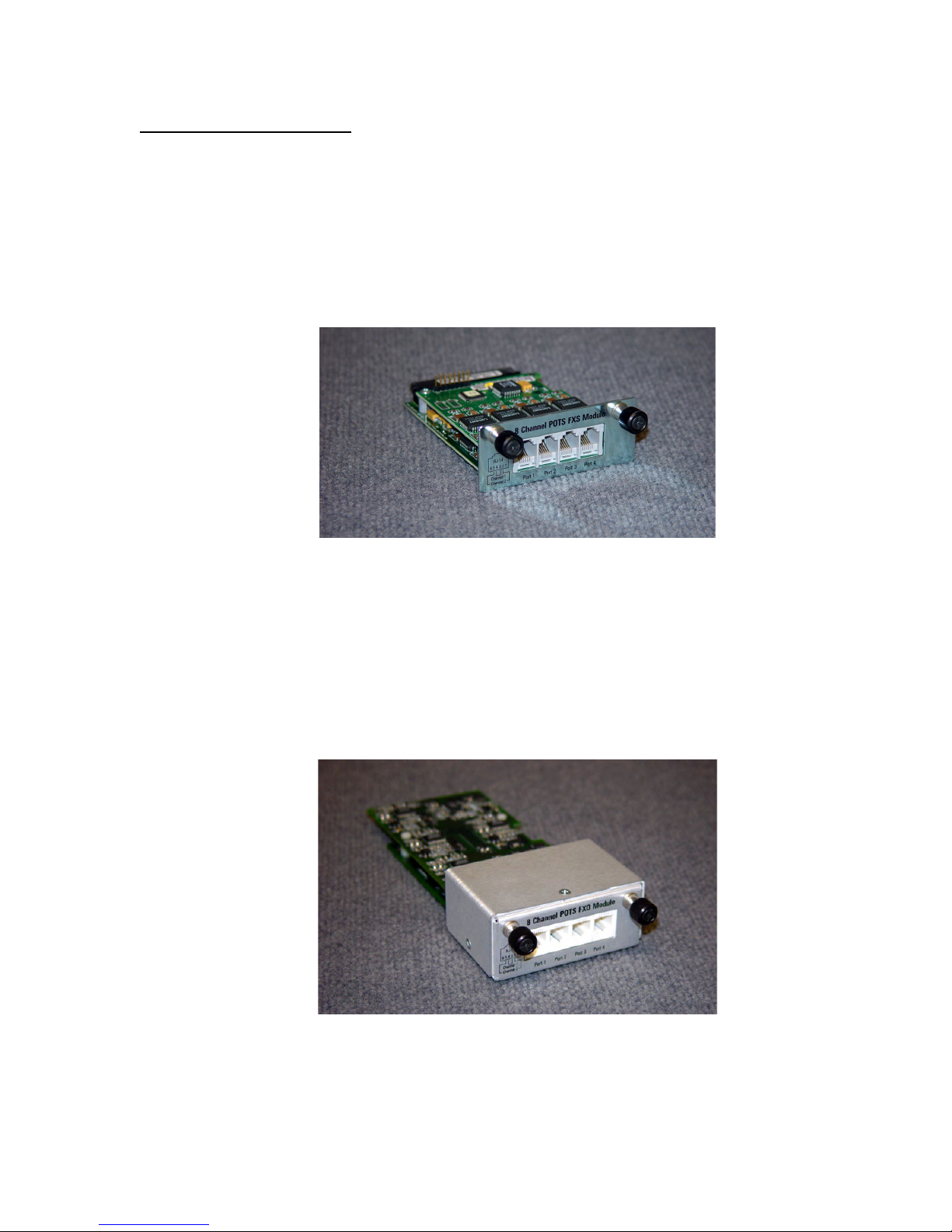
The 8 Channel POTS FXS interface module (see Figure 9) provides eight (8)
channels which appear as Central Office or PBX lines. The interface provides battery,
ringing and call progress to the equipment under test, and can detect on and off-hook
conditions and DTMF signaling from the connected equipment.
The interface uses industry standard RJ11 jacks wired to RJ14 standards.
Figure 9. 8 Channel POTS FXS Module
8 Channel POTS FXO Module
The 8 Channel POTS FXO interface module (see Figure 10) provides eight (8)
channels which appear as telephones to the equipment under test. The interfaces can
detect ringing, go on and off-hook and transmit DTMF dialing.
The interface uses industry standard RJ11 jacks wired to RJ14 standards.
Figure 10. 8 Channel POTS FXO Module
40-400-00065, Rev. E
7
Page 18

TSP Edge User’s Manual
4 Channel POTS Module (Discontinued)
The 4 Channel POTS interface module provides four (4) channels which appear as
Central Office or PBX lines. The interface provides battery, ringing and call progress
to the equipment under test, and can detect on and off-hook conditions and DTMF
signaling from the connected equipment.
The interface uses industry standard RJ11 jacks.
The 4 channel POTS module is identical to the 8 channel FXS module, except there is
only 1 channel available per port.
Advanced Software Modules
TSP-PRI
TSP-PRI (Primary Rate ISDN): This software module includes the standard Edge
features plus it adds either T1 or E1 Primary Rate ISDN to an Edge unit that has no
PRI capability licensed.
T1 Primary Rate ISDN:
• Includes multiple switch types:
o US National ISDN-2
o AT&T 4ESS
o AT&T 5ESS
o NT DMS-100/250
• Simulates CPE end or Network end
• Provides the following capabilities:
o Direct dialing in (DID)
o Subaddressing
o Delivery of Called and Caller number (CLIP)
o Delivery of Type of Address and Numbering Plan
E1 Primary Rate ISDN:
• Includes EURO-ISDN switch type
• Simulates CPE end or Network end
• Provides the following capabilities:
o Direct dialing in (DID)
o Subaddressing
40-400-00065, Rev. E
8
Page 19
TSP Edge User’s Manual
o Delivery of Called and Caller number (CLIP)
o Delivery of Type of Address and Numbering Plan
TSP-2PRI
The TSP-2PRI software module adds either T1 or E1 Primary Rate ISDN to an Edge
unit that already has one of the two types installed.
TSP-ATS
TSP-ATS (Advanced Test Scripting): This software module includes the standard
Edge features plus user defined scripts including:
• User-definable call sequences
• Send DTMF during a call
• Detect DTMF during a call
• Send test tones
• Detect broadband energy
• Detect voice
• Play multiple wave files on a channel
License Codes
Edge license codes are used for:
• Enabling additional purchased software modules
• Setting warranty information
For information about upgrading the Edge, see “Upgrades Tab” on page 48.
SETUP
System Requirements
Power
Caution: AC operating power must be within 90 to 250 volts AC and the
operating frequency from 43 to 63 Hz.
The Edge unit uses an industry standard IEC three prong connector so that almost any
international power cord can be used. A standard North American power cord is
provided with the unit.
40-400-00065, Rev. E
9
Page 20

TSP Edge User’s Manual
PC
• PC with Windows 95/98/XP/2000 or Windows NT
• Serial port interface on PC (standard RS-232 DCE interface – cable provided
with Edge)
• Ethernet connection to PC (crossover cable with RJ45 connectors provided) or
to LAN (standard Ethernet cable not provided)
• Monitor, keyboard, and mouse or equivalent devices
• 2X Speed CD-ROM drive
The following minimum disk storage capacities are required for the basic installation
and storage of saved files:
6 Mb required on the disk with the Windows operating system
4 Mb required on the disk the application is installed on
7 Mb additional required to install the Adobe Acrobat reader
Checking Your Edge Package
When you receive your Edge unit, you should receive the following components:
• TSP-EDGE-01 unit
• 120 VAC power cord
• RJ45 Ethernet cross over cable (gray cable, labeled)
• RJ11 serial cable
• RJ11 to DB9 adapter
• RJ11 to DB25 adapter
• Two RJ45 - T1/E1 cables (yellow cable, labeled)
• Rack-mount Bracket Kit (2 brackets and 8 mounting screws)
• Edge Configuration Software (CD-ROM)
• Product Registration Card
Optional Hardware
• Dual T1/E1 interface module
• 8 Channel POTS FXS interface module
• 8 Channel POTS FXO interface module
• Y-Cable Kit (set of 4, to use with 8 Channel POTS interface modules)
40-400-00065, Rev. E
10
Page 21
TSP Edge User’s Manual
Optional Software Modules
• TSP-PRI: Adds T1 or E1 Primary Rate ISDN (you select T1 or E1 upon
installation) NOTE: For older TSP-BASE units, only T1 PRI is available.
• TSP-2PRI: Extends TSP-PRI module to include both T1 and E1 Primary Rate
ISDN. NOTE: For TSP Edge units only.
• TSP-ATS, Advanced Test Scripting software module. NOTE: For TSP Edge units
only.
If any of the items you ordered are missing or damaged, please contact Teltone
customer service.
Caution: The Edge modules are (electro-static discharge) sensitive devices and
are shipped in static shield packaging. Proper precautions are needed to avoid
damaging them when handled. Teltone Corporation requires any returned
modules to be properly packaged in static shield packaging.
Installing Hardware Modules
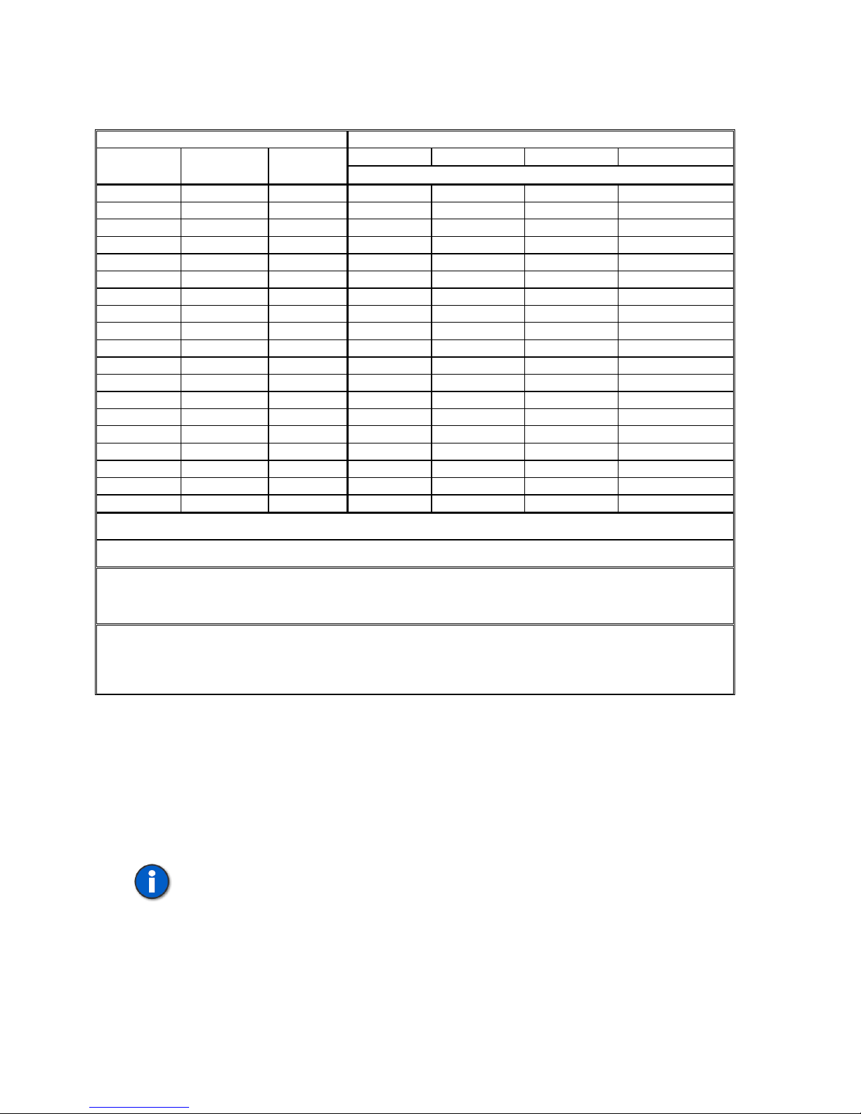
Before applying power to the Edge, ensure that the telephony interface modules are
installed per the following information and Table 1. Ensure the modules are securely
seated and the thumb-screws are tightened.
Note: Slot count is 1-4 from left to right when looking at the back of the Edge.
1. If using a T1/E1 module, install it in slot 4.
a. Two T1/E1 modules may be used ONLY if they are both Single T1/E1
modules and no other modules are installed. Install the Single T1/E1
modules in slots 3 and 4.
2. When installing POTS modules (both FXO and FXS types), install the first
module in slot 3 and work to the left.
a. If installing both FXO and FXS modules, place the FXS modules to the
left of the FXO modules.
b. If installing both 4 and 8 Port POTS FXS modules, place the 4 Port
module to the left of the 8 Port module.
c. When using a 4-Port POTS module, at most only one other module may
be installed.
40-400-00065, Rev. E
11
Page 22
TSP Edge User’s Manual
Table 1. Module Interface Matrix
Number of Each Module Type Module Placement
Slot 1 Slot 2 Slot 3 Slot 4 8 Channel
Slot count is 1-4 from left to right when looking at the back of the Edge.
POTS FXS
8 Channel
POTS FXO
Dual Port
T1/E1
1 T1/E1
1 POTS-FXO
2 POTS-FXO POTS-FXO
3 POTS-FXO POTS-FXO POTS-FXO
1 1 POTS-FXO T1/E1
2 1* POTS-FXO POTS-FXO T1/E1*
3 1* POTS-FXO POTS-FXO POTS-FXO T1/E1*
1 POTS-FXS
2 POTS-FXS** POTS-FXS**
3 POTS-FXS POTS-FXS POTS-FXS
1 1 POTS-FXS** T1/E1
2 1* POTS-FXS POTS-FXS T1/E1*
3 1* POTS-FXS POTS-FXS POTS-FXS T1/E1*
1 1 POTS-FXS** POTS-FXO
1 2 POTS-FXS POTS-FXO POTS-FXO
2 1 POTS-FXS POTS-FXS POTS-FXO
1 1 1* POTS-FXS POTS-FXO T1/E1*
1 2 1* POTS-FXS POTS-FXO POTS-FXO T1/E1*
2 2 1* POTS-FXS POTS-FXS POTS-FXO T1/E1*
* Only the second port of a Dual-T1/E1 module will be active if more than one POTS module is installed. Port 1 of a Dual-
T1/E1 module will be disabled in these configurations.
** A 4 Port POTS module may be used in place of an 8 Port POTS FXS module in these configurations. The 4 Port POTS
module must be installed to the left of any other module.
If using Single T1/E1 modules:
A Single T1/E1 module may be used in place of the Dual T1/E1 module in any of the above configurations.
Two Single T1/E1 modules may be used if no other modules are installed in the Edge. The modules must be placed in slots
3 and 4.
If using 4 Port POTS modules:
A 4 Port POTS module may be used in place of an 8 Port POTS FXS module in any configuration in which there are at
MOST two modules. The 4 Port POTS module must be installed to the left of any other module.
Two 4 Port POTS modules may be used only if no other modules are installed in the Edge. The modules must be placed in
slots 2 and 3.
Communications Connections
Configuring and control of the Edge can be done with either a serial connection to a
PC or with an Ethernet connection directly to a PC or to a LAN. It is necessary to use
the serial connection to initially program the IP for the Ethernet connection.
For pin-out details, see “Connector and Cable Pin-outs” on page 152.
Important: When using the T1/E1 module in T1-PRI or E1-PRI mode, the
network connection must be used for programming and control; the serial
connection is not allowed. This allows for enhanced messaging during PRI
operation.
40-400-00065, Rev. E
12
Page 23
TSP Edge User’s Manual
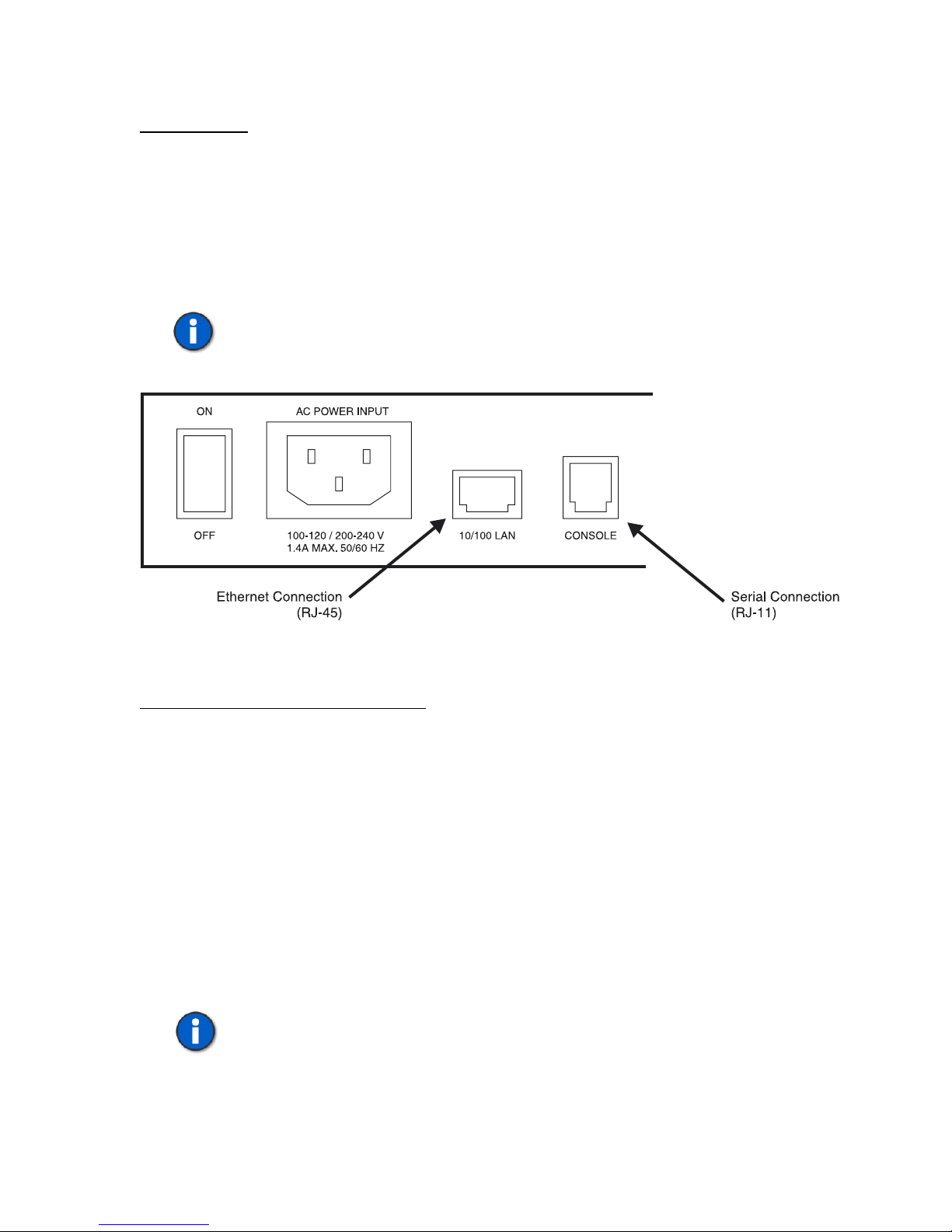
Console Port
The Console Port is an RS-232 serial connection for configuration and control of the
Edge. The connection is an RJ11 jack on the Edge, with cables and adapters provided
for connection to either a DB9 or DB25 connection on the PC.
Connect the serial cable (RJ11 jack at both ends) to the Edge at the jack labeled
Console. Connect the other end to the PC’s serial port using the DB9 or DB25
adapter.
Important: Initial programming of the Edge must be done with this connection.
Figure 11. Serial and Ethernet Connections on the Edge Back Panel
10/100 LAN (Ethernet) Connection
The network connection is a 10/100 Base-T which can be used for configuration and
control of the Edge, and which is necessary for downloading voice messages and
software upgrades to the Edge.
An Ethernet cross-over cable (RJ45 at both ends) is provided for connecting directly
to a PC. If connecting via a network hub, a standard straight-through network cable is
required. See “Network Connection” on page 21 for more details.
Powering Up the Edge
The Edge uses a universal power supply that operates from 90 to 250 VAC, 43 to 63
Hz. Connect the power cord and turn on the unit using the switch on the back of the
unit.
Note: Grounding is assured by using the appropriate (approved) power cord.
40-400-00065, Rev. E
13
Page 24

TSP Edge User’s Manual
The green POWER LED on the front panel will indicate the status of the system. The
LED should be solid green. If the LED fails to light, check your power connections
and verify the switch is in the ON position. If the LED still fails to light, disconnect
power immediately and contact Teltone Technical Support at 425-951-3390.
Important: Adequate airflow must be maintained in order for the unit to
operate correctly. Do not wrap the unit in blankets, paper or other material that
may impede ventilation.
Installing Edge Software
The Edge configuration software is supplied on a CD-ROM disk and uses the
common Windows setup routine. Ensure you have the latest version by going to the
Teltone website (www.teltone.com) and verifying the version available or call
Teltone technical support.
An autorun facility initiates the installation process automatically when the CD-ROM
is installed into the disk drive. An alternative method is to insert the CD-ROM, then
select START, RUN, BROWSE, then choose your CD-ROM drive, and the file
labeled SETUP.EXE. Follow the on screen instructions.
For information about the current and previous versions of the software, see
“Revision History” on page 119.
PROGRAMMING THE EDGE
The Edge configuration software installed on the PC controls the Edge unit and its
configuration. Multiple projects can be saved and used for different testing
applications and units.
Basics
The Edge configuration software allows a user to define Edge Project configurations
in terms of Units, Templates, and Control Sets.
A Unit defines the configuration of a physical Edge unit, the communications
interface used to control it, the hardware modules installed in it, and configuration
parameters for those hardware modules. Within a unit are:
• Slots - the physical card slots where modules are installed
• Ports - the individual connectors on the modules
• Channels - the individual lines or timeslots on each port. Each channel is
identified throughout the configuration software using a unique ID string,
based upon the channel’s location within a particular unit (see “Channel
Identification” on page 30).
40-400-00065, Rev. E
14
Page 25
Templates define protocols, timings and signaling to be applied to channels within
one or more units.
Control Sets define the action to be taken (such as call origination), which channels
are to be used, what templates are assigned to those channels, and when the action is
to start and stop.
Main Window
Once all connections have been made and the unit is powered up, start the Edge
configuration software.
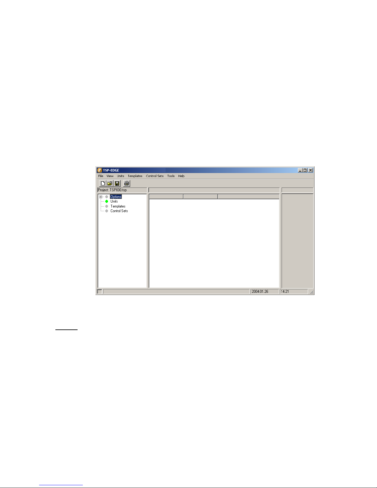
The main window starts with a default project file and is ready for configuring the
Edge (see Figure 12).
TSP Edge User’s Manual
Figure 12. Configuration Software New Project
Menus
File – for creating, opening and saving project files, and exiting the program.
View – to access and clear the event log and to access Options.
Units – to edit unit-specific parameters for each Edge unit, and to initialize a unit.
Templates – to edit templates.
Control Sets – to edit control sets.
Tools – to access the Diagnostic and Trace functions.
Help – to access the Help file and About dialog box.
40-400-00065, Rev. E
15
Page 26
TSP Edge User’s Manual
Tree Display
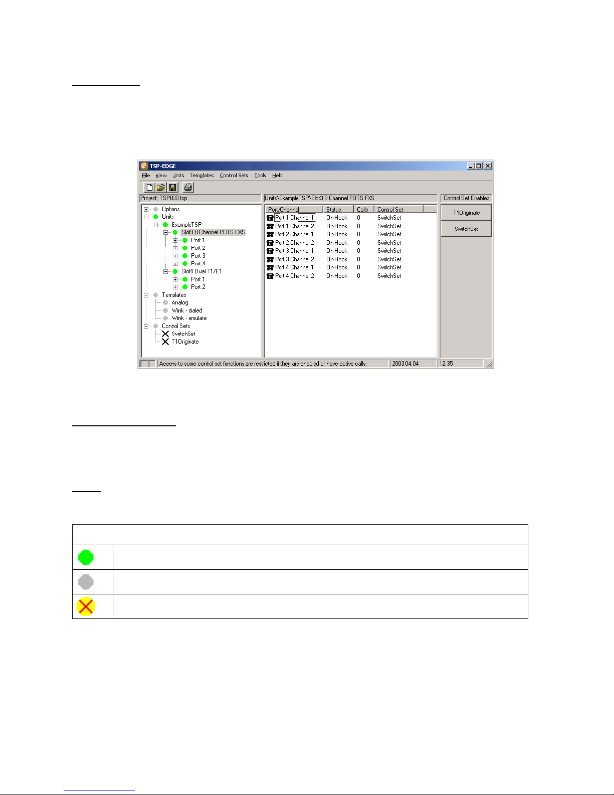
On the left side of the main window is a tree display for Options, Units, Templates,
and Control Sets. A plus sign (+) appears in front of each of these as simulation
parameters are created. Clicking the plus sign (+) expands the display tree and
clicking the minus sign (-) does the opposite. See Figure 13.
Information Section
To the right side of the tree display is the information section. The information
section displays parameters and current states of the item chosen in the tree display.
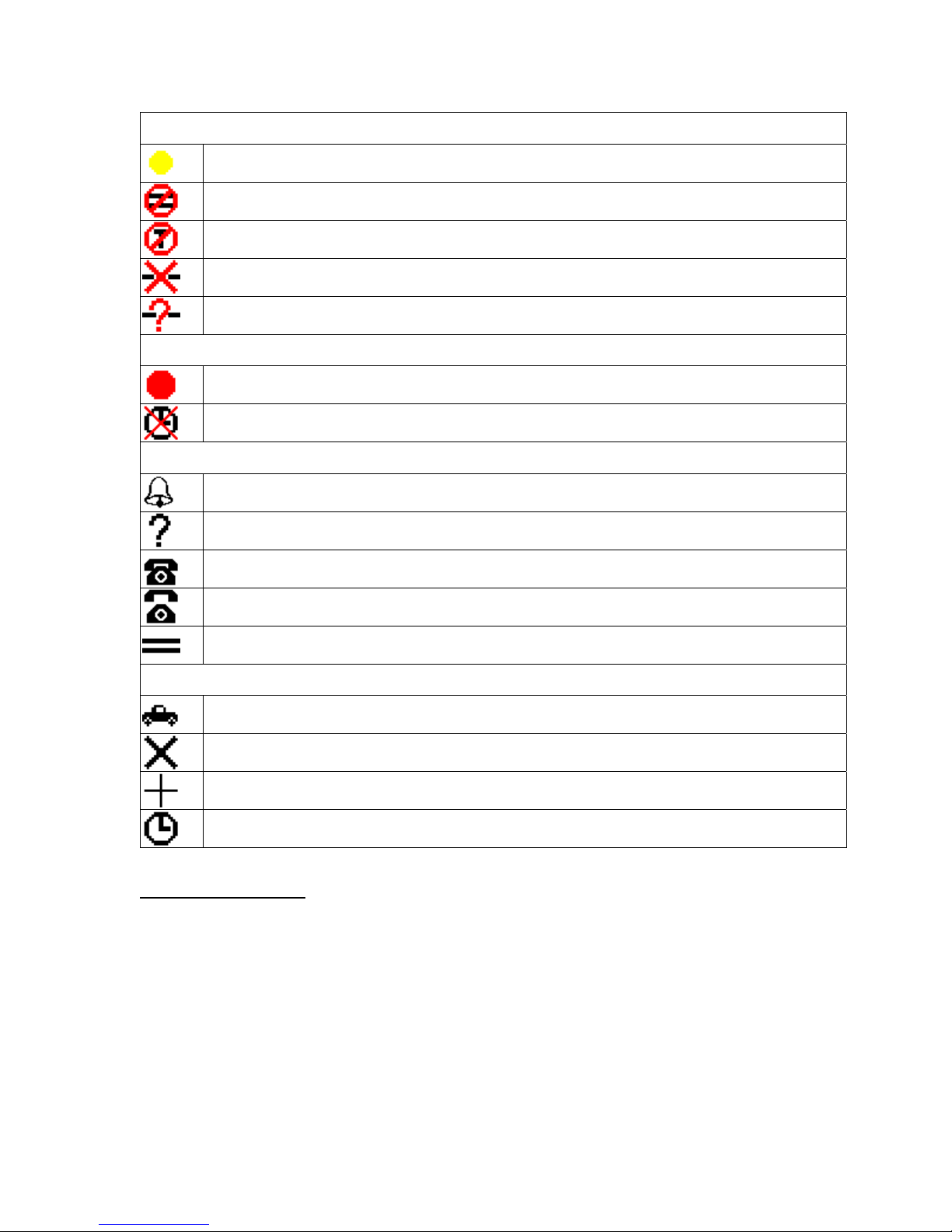
Icons
The following icons are used in the tree display and information section.
Everything is OK. (Green Dot)
This item has no status. (Gray Dot)
Error lower in tree. (Yellow Dot with Red X)
Figure 13. Main Window
General Status
40-400-00065, Rev. E
16
Page 27
TSP Edge User’s Manual
Unit Status
Attempting to communicate with Edge. (Yellow Dot)
Card Definitions do not match.
Unit connected is not an Edge unit or requires a license code.
Communication error to unit.
No Comm port defined for unit.
T1/E1 Alarms
T1/E1 Alarm (Red Dot) - Check that the T1/E1 cable is connected and that the T1/E1
parameters for the connected device are configured the same as the unit.
T1/E1 Clock Sync Error - Check that the T1/E1 parameters for the connected device are
configured the same as the unit.
Channel Status
Channel is ringing.
No status available.
Channel is On-hook.
Channel is Off-hook.
Clear Channel
Control Set Status
Control set is running.
Control set Disable.
Control Set Finished.
Control Set Waiting for Start Time
Control Set Enables
The Control Set Enable buttons appear on the far right side of the main window once
Control Sets have been created. These buttons are used to activate control sets.
During programming and control of the Edge, the small box at the bottom left corner
of the main window turns yellow indicating commands are being sent to the Edge.
Once complete, the box turns gray.
40-400-00065, Rev. E
17
Page 28
TSP Edge User’s Manual
Units
Unit Configuration
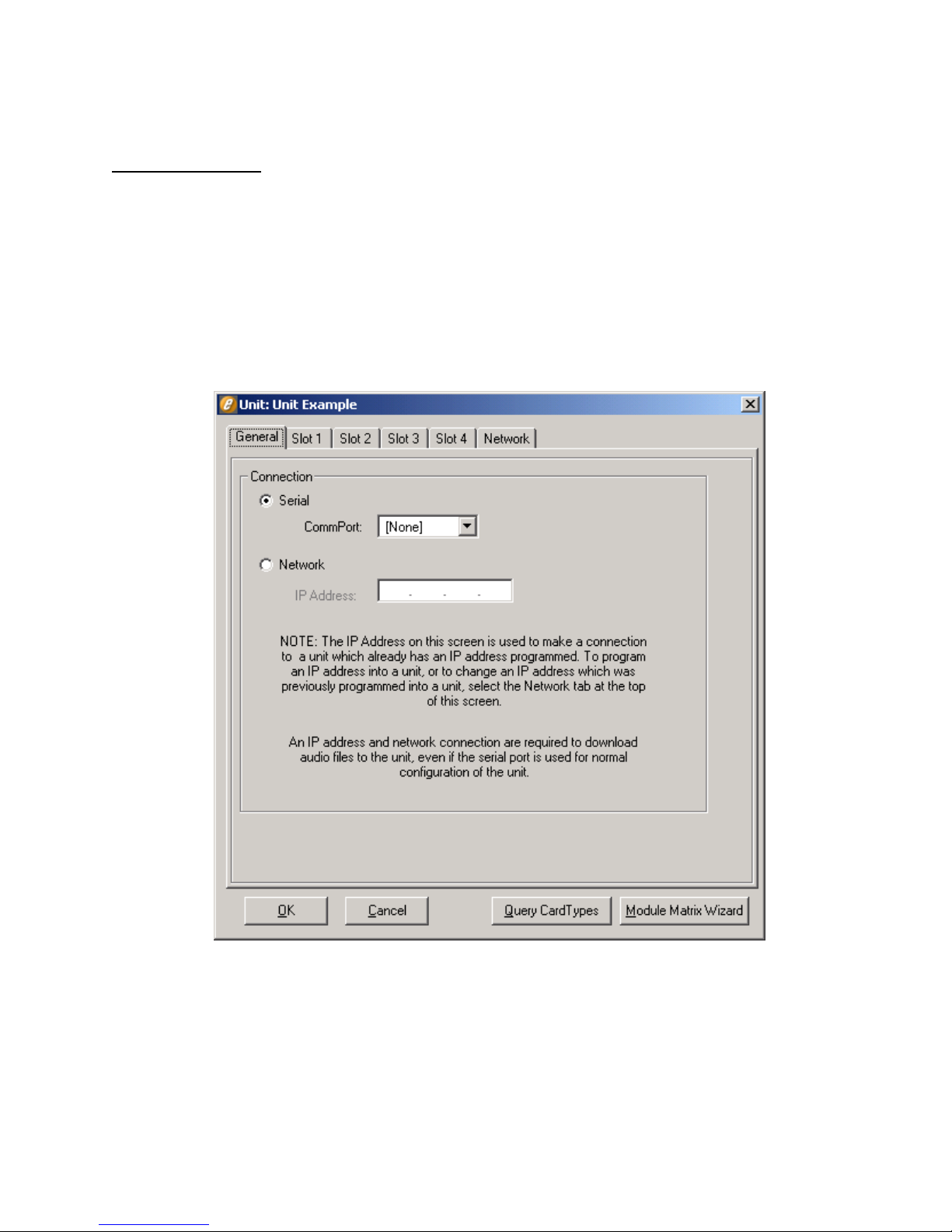
Each Edge must be defined as a “Unit” in the configuration software. The Unit screen
(see Figure 14) is used to define the connection for communicating to the Edge, the
card types installed in the unit, and specific information for the Ports and Channels on
each card.
By clicking New on the Units menu, the prompt “Enter New Unit Name” appears.
For demonstration purposes, the name “Unit Example” is used in this manual. After
entering the name for your unit, the Unit screen is displayed (see Figure 14) with the
unit name in the title bar.
Note the tabs on the Unit screen: General (Connection for Serial or Network
control), Slots 1 - 4 (for card types), and Network (for assigning an IP address to the
unit).
40-400-00065, Rev. E
18
Figure 14. Unit Screen
Page 29

The Unit screen is displayed with the General tab selected. This tab is used to select
the type of connection that will be used to communicate to the Edge. A Serial
connection must be used initially since no IP address is assigned for a Network
connection at this point.
Serial Connection
The serial connection is mandatory for initial setup of the Edge. It must be used to
establish control of the unit and to set it up for network control. Select the
CommPort that will be used to control the unit.
When using a T1/E1 module in T1-PRI or E1-PRI mode, a network connection
must be used for programming and control; a serial connection is not allowed.
This allows for enhanced messaging during PRI operation.
Query Card Types
At this point, the unit in the Edge configuration software can be configured to match
the modules installed in the physical unit. This can be done automatically by clicking
the Query Card Types button at the bottom of the Unit screen. A message is displayed
stating “This will set the current units card types to match those actually in the
system”. Click OK to continue. The Unit screen’s slot information now reflects the
physical modules in the unit.
TSP Edge User’s Manual
Teltone recommends using the Query Card Types button for configuring the Edge.
But, if the unit is not connected to the PC, manual configuration can be done by
selecting the Unit screen Slot tab that corresponds with the position of a module.
Then configure the Card Type by selecting the appropriate card type. Later, when you
connect to the Edge, download the configuration by selecting Initialize on the Units
menu.
When you click the Query Card Types button, if the physical modules in the unit are
installed incorrectly, a message refers you to the Module Matrix Wizard for the
proper setup.
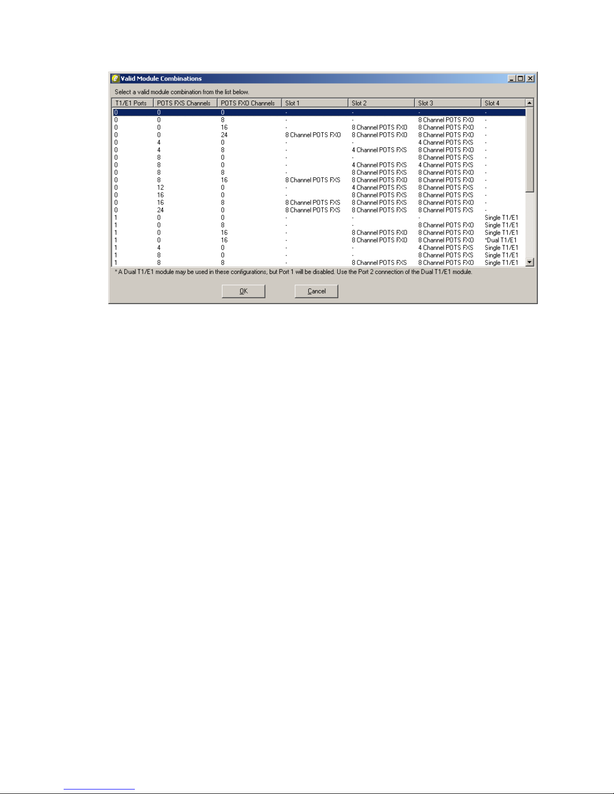
The Module Matrix Wizard button on the Unit screen (see Figure 14) can be used to
select valid module installation configurations. After clicking the Module Matrix
Wizard button, the Valid Module Combination dialog box is displayed, as shown in
Figure 15.
40-400-00065, Rev. E
19
Page 30
TSP Edge User’s Manual
Figure 15. Module Matrix Wizard
Selecting a module combination in the Valid Module Combination dialog box and
then clicking OK sets all of the card types on the Unit screen. For more information,
see “Installing Hardware Modules” on page 11.
After configuring the card types, click OK on the Unit screen.
Newer Software Versions
If the Edge software version on the PC is newer than the code in the unit, a message
is displayed:
Newer code is available for unit ‘xxx’. Do you wish to
download to your unit now? Note: You must have a network
connection to the unit to download.
The Edge must have an Ethernet connection and an IP address assigned for the
download to be successful. Click No if this has not been done and follow the
instructions in the next subsection. Once the Edge is assigned an IP address,
download the newer version to the unit by clicking OK on the Unit screen or by
selecting Initialize on the Units menu. This can be done with either the Serial or
Network Connection selected on the General tab of the Unit screen.
If it’s indicated that the code in the Edge is newer than that on the PC, download the
latest version of the software from the Teltone website (www.teltone.com).
40-400-00065, Rev. E
20
Page 31

Network Connection
A network connection can be used for programming and controlling the Edge, and for
downloading audio files and software upgrades to the unit. It must be used when a
T1/E1 module is programmed for T1-PRI or E1-PRI mode to allow for enhanced
messaging. The initial setup of the IP address for the network connection must be
done from the Network tab on the Unit screen via the serial connection. The Network
tab is used to assign a new IP address or to change an existing IP address (see
“Changing an IP Address” on page 22).
The IP Address field on the General tab displays the IP address of the currently
connected unit. The field is also used to connect to units that have already been
assigned an IP address. Even if the serial connection is used for controlling the unit,
the Ethernet connection is still required if using audio files or downloading newer
version software.
To configure the IP address, ensure you have connected the unit’s Ethernet port either
to the LAN with a straight-through cable or to the PC directly using the crossover
cable provided.
TSP Edge User’s Manual
If connecting to a LAN, contact your network administrator to assign a static IP for
the unit.
To enter the IP address, go to the Units menu, click the unit name and select the
Network tab on the Unit screen. Use a valid IP format that is in the same subnet and
uses a valid subnet mask. Click OK.
Network Control
A network connection can be used for controlling the Edge. Only a PC on the same
subnet as the unit can control it via the network.
To enable network control, select the unit on the Units menu. On the Unit screen
General tab, the IP address programmed into the unit will be displayed. Select
Network connection and click OK. The unit is controlled via the Ethernet connection
at this point.
If the unit’s IP address is not displayed on the Unit screen, follow the instructions in
the previous subsection first.
Connecting to a Unit on the Network
You can connect your PC to any Edge that has been assigned a valid IP address and is
on the network. The Edge configuration software remembers the names and IP
addresses of all the units that your PC has connected to.
If your PC has previously connected to the unit, select New on the Units menu. In the
New Unit dialog box, select the unit you wish to connect to. This automatically enters
40-400-00065, Rev. E
21
Page 32

TSP Edge User’s Manual
the last known IP address for that unit. If not, first create a new unit, select Network
connection, and enter the IP address of the unit you wish to connect to.
Then click the Query Card Types button and click OK. The Query Card Types
function matches the modules in the physical unit to the card types in your Edge
configuration software project. If you skip this step, an error message may appear
advising that the card types do not match.
Override
If a unit is accessed when it is in use, an Override message appears. The machine
name of the party using it is displayed, and the option to override the connection is
provided. If the override is implemented, the PC that was previously connected to the
unit receives a Communication Error message advising of the network connection
override and the machine name of the party that took control. All override actions are
recorded in the event log (see “Event Log” on page 52).
The override feature is used to regain control of a unit in case the controlling PC loses
its network connection. It also facilitates controlling the unit from different locations.
To take control back when a connection is overridden, go to the Units menu, choose
Initialize and the name of the unit.
Changing an IP Address
To change the IP address of a unit, go to the Units menu and select the unit. The Unit
screen is displayed. Choose the Network tab, enter the new IP address, and click OK.
The Edge now has the new IP address, and the PC is communicating with the Edge
using the new IP address.
If you open a project that has an old IP address for a unit, a message advises you of
the new IP address and asks if you want to change to the new IP address. This
message is only provided on the PC that was controlling the unit when the IP address
was changed.
Viewing Unit Information
To view a unit’s hardware ID, warranty expiration dates, license code, and other
information:
1. Connect to the Edge.
2. If you have not yet created a Unit Name, do so now (see “Units” on page
18).
3. In the Edge configuration software main window, expand the Units node
of the tree display and click the name of the connected unit.
The hardware ID, warranty expiration dates, etc. are displayed in the information
section.
40-400-00065, Rev. E
22
Page 33
Unit Configuration Summary
1. Select New on the Units menu and name the unit.
The Unit dialog box is displayed.
2. In the Unit dialog box, configure the Serial Connection setting on the
General tab by selecting the appropriate Comm Port.
3. Click the Query Card Types button at the bottom of the Unit dialog box.
The information on the Slot tabs in the Unit dialog box now reflects the physical
modules in the Edge.
4. Click OK in the Unit dialog box.
5. If a message stating that "Newer code is available" is displayed, click No
and follow the instructions in “Newer Software Versions” on page 20.
6. Re-open the Unit dialog box for your unit.
7. If network control is needed, assign a valid IP address to the unit, and
select Network connection.
TSP Edge User’s Manual
Module Configuration
Slot Tabs
Once the card types and the connection to the Edge are defined, there are many
different options to configure for each card type. Choose each Slot tab that has a
module installed and configure it according to the following subsections.
Single T1/E1 and Dual T1/E1 Card Types
For T1/E1 modules, the Card Mode field is displayed to the right of the Card Type
field. T1 is displayed by default. Clicking the arrow displays the E1, T1-PRI and E1PRI options.
Note: T1-PRI and E1-PRI are available when optional software module(s) are
purchased. For more information, see “Primary Rate ISDN Software Modules
(TSP-PRI and TSP-2PRI)” on page 87.
When using two single T1/E1 modules, both modules have to be configured for the
same card mode and PCM encoding/companding. Therefore, the selections for Card
Mode and mu-law or a-law are disabled for one of the slots.
40-400-00065, Rev. E
23
Page 34
TSP Edge User’s Manual
T1 Card Mode
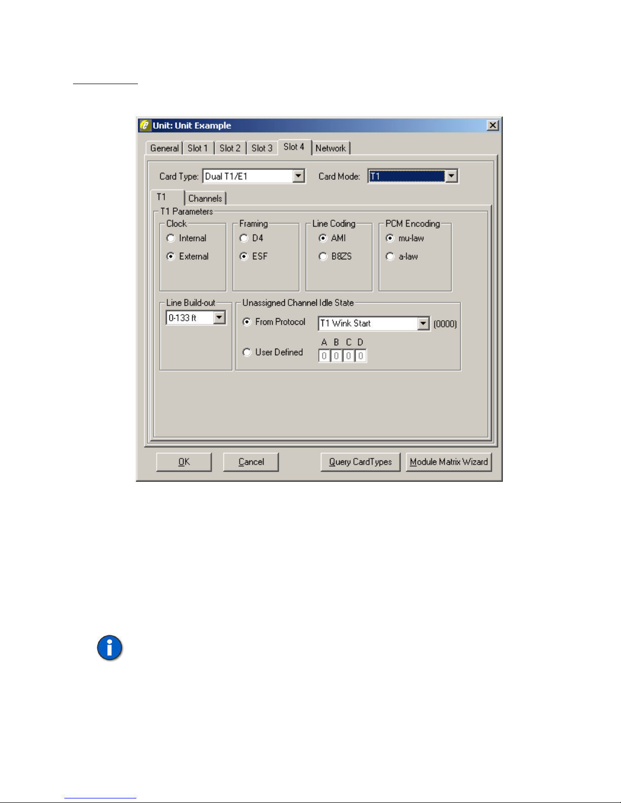
Figure 16 shows the parameters on the T1 tab in the T1 card mode.
Figure 16. T1 Card Mode T1 Tab
Clock
The Clock needs to be set to where one end is providing timing (normally the PSTN)
while the other end is deriving clock from it (usually the CPE). The Internal clock
setting is used when the Edge acts as the PSTN and provides the clocking to the
equipment under test. External Clock is used when the Edge acts as the CPE and
clocks from the equipment under test (i.e., if the Edge is set for Internal clock, the
equipment under test should be set for External clock, and vice versa).
Note: If using only one port on a Dual T1/E1 that is configured for External
Clock, port 2 must be used and will derive its clock from the equipment
under test. If using both ports, the device connected to Port 1 must use the
same clocking reference as the device connected to port 2.
40-400-00065, Rev. E
24
Page 35

TSP Edge User’s Manual
Framing
With Framing, both ends need to match, otherwise synchronization will not be
achieved. D4 is considered a more common format while ESF (extended superframe)
provides for overhead features such as a data link and CRC-6 for detection of errors
without interrupting the signal. The Edge does not report data link information for
CRC-6 errors.
Line Coding
For Line Coding, AMI suffices if no DDS data exists on any of the T1 channels.
B8ZS is used when DDS data channels are present to compensate for when an all
Zeros state exists (when equipment is off). This can lead to loss of synchronization on
the T1 data stream due to too many successive zeros.
PCM Encoding
For PCM Encoding, the choices are mu-law and a-law. For T1, mu-law is the default.
This is the PCM encoding and companding standard used in North America and
Japan. For E1, a-law is the default and is the PCM encoding and companding
standard used in Europe.
Important: On Dual T1/E1 modules, both ports are configured for the same
clock, framing , and line coding. Ensure the parameters are consistent with the
configuration of the equipment under test. This information can be found in the
equipment manual or by contacting the vendor.
Line Build-out
The Line Build-out defaults to 0-133 ft (0 dB level) but can be changed for different
distances or dB loss expected on the line.
Unassigned Channels Idle State
The Unassigned Channels Idle State defines the signaling state for T1 channels that
have not been assigned to any control set, and therefore are not associated with any
template. You can select an idle signaling state associated with a particular protocol
or define the actual bit pattern directly.
To change the default idle state for unassigned channels, see “Unassigned Channels
Tab” on page 50. For information about the Channels tab, see “Channels Tab” on
page 29.
40-400-00065, Rev. E
25
Page 36
TSP Edge User’s Manual
E1 Card Mode
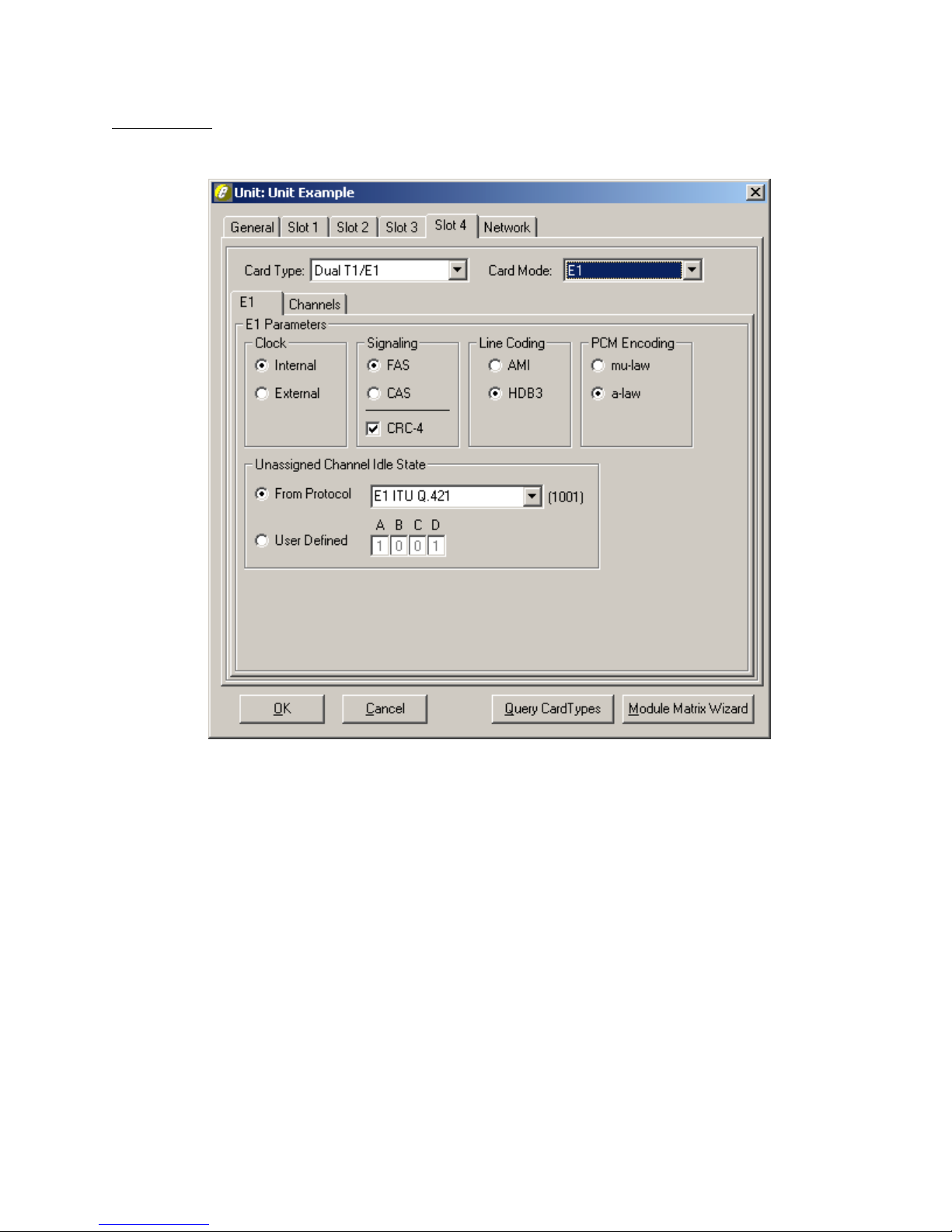
Figure 17 shows the parameters on the E1 tab in the E1 card mode.
Figure 17. E1 Card Mode E1 Tab
The Edge is capable of supporting up to 56 channels depending on configuration. In
the case where two E1s are configured for the unit, the last 4 channels of the second
E1 do not support messages or call progress tones and may only be used in Call
Originate and Call Terminate control sets. Also, if a Dual E1 module and a POTS
module are used, the last 8 channels (for 4 Channel POTS) or the last 12 channels (for
8 Channel POTS) are unavailable on the second E1.
Clock
The Clock needs to be set to where one end is providing timing (normally the PSTN)
while the other end is deriving clock from it (usually the CPE). The Internal clock
setting is used when the Edge acts as the PSTN and provides the clocking to the
equipment under test. External Clock is used when the Edge acts as the CPE and
clocks from the equipment under test (i.e., if the Edge is set for Internal clock, the
equipment under test should be set for External clock, and vice versa).
40-400-00065, Rev. E
26
Page 37

Signaling
With Signaling, both ends need to match, otherwise synchronization will not be
achieved. CAS is considered a more common format for voice traffic while FAS is
used for data traffic. The CRC-4 option is used for error detection. The Edge does not
report CRC-4 information.
Line Coding
For Line Coding, AMI suffices if no DDS data exists on any of the E1 channels.
HDB3 is used when DDS data channels are present to compensate for when an all
Zeros state exists (when equipment is off). This can lead to lost of synchronization on
the E1 data stream due to too many successive zeros.
PCM Encoding
For PCM Encoding, the choices are mu-law and a-law. For T1, mu-law is the
default. This is the PCM encoding and companding standard used in North America
and Japan. For E1, a-law is the default and is the PCM encoding and companding
standard used in Europe.
TSP Edge User’s Manual
Note: If using only one port on a Dual T1/E1 that is configured for External
Clock, port 2 must be used and will derive its clock from the equipment under
test. If using both ports, the device connected to Port 1 must use the same
clocking reference as the device connected to port 2.
Important: On Dual T1/E1 modules, both channels are configured for the same
clock, signaling, and line coding. Ensure the parameters are consistent with the
configuration of the equipment under test. This information can be found in the
equipment manual or by contacting the vendor.
Unassigned Channels Idle State
The Unassigned Channels Idle State defines the signaling state for E1 channels that
have not been assigned to any control set, and therefore are not associated with any
template. You can select an idle signaling state associated with a particular protocol
or define the actual bit pattern directly.
To change the default idle state for unassigned channels, see “Unassigned Channels
Tab” on page 50. For information about the Channels tab, see “Channels Tab” on
page 29.
40-400-00065, Rev. E
27
Page 38
TSP Edge User’s Manual
4 Channel POTS and 8 Channel POTS FXS Card Types
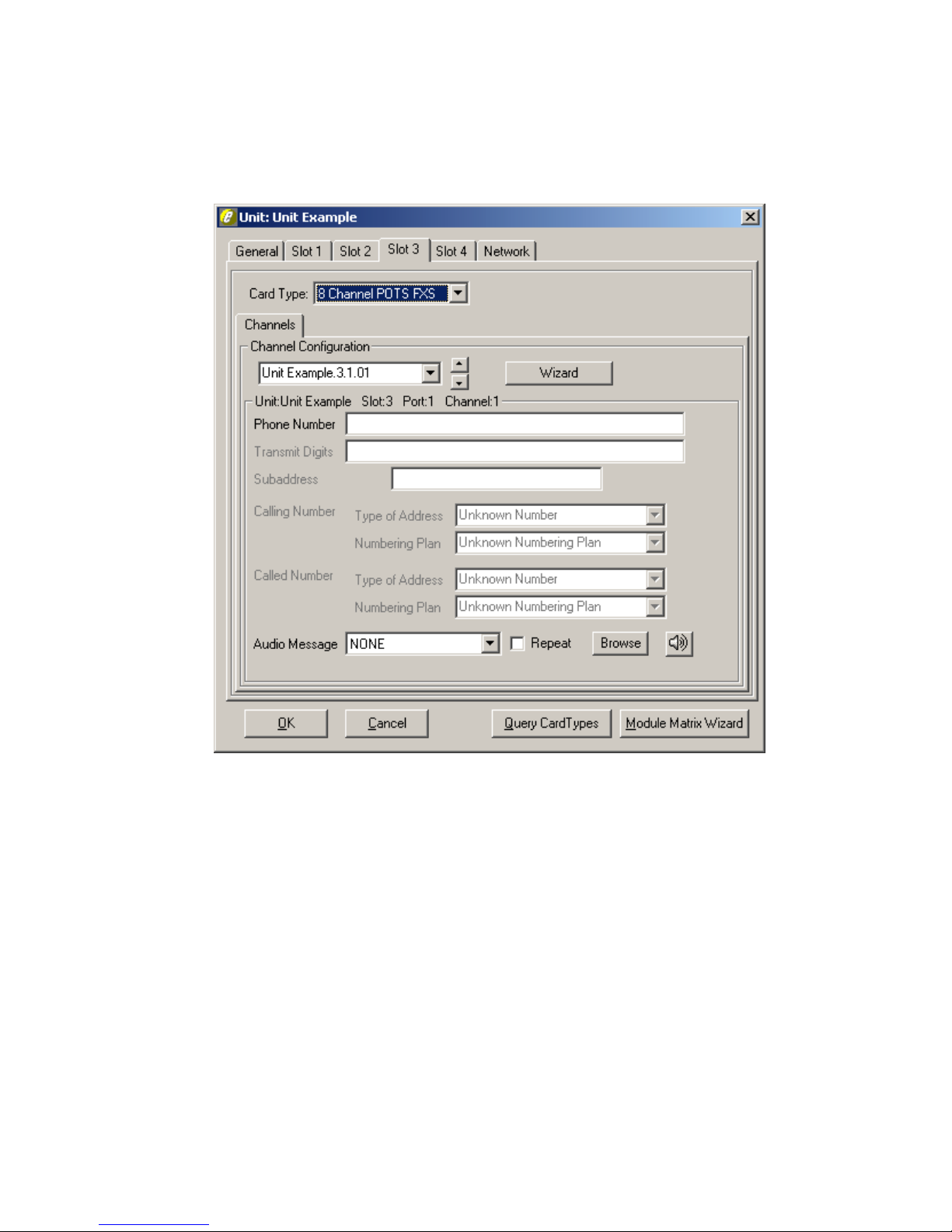
When either of these card types is selected, only a Channels tab is displayed (see
Figure 18).
Figure 18. POTS FXS Card Type
The 4 Channel POTS and 8 Channel POTS FXS Card Type screens are identical. The
only difference is the number of channels available to configure. These channels
operate as Analog Loop Start FXS only.
For information about the Channels tab, see “Channels Tab” on page 29.
40-400-00065, Rev. E
28
Page 39
8 Channel POTS FXO Card Type
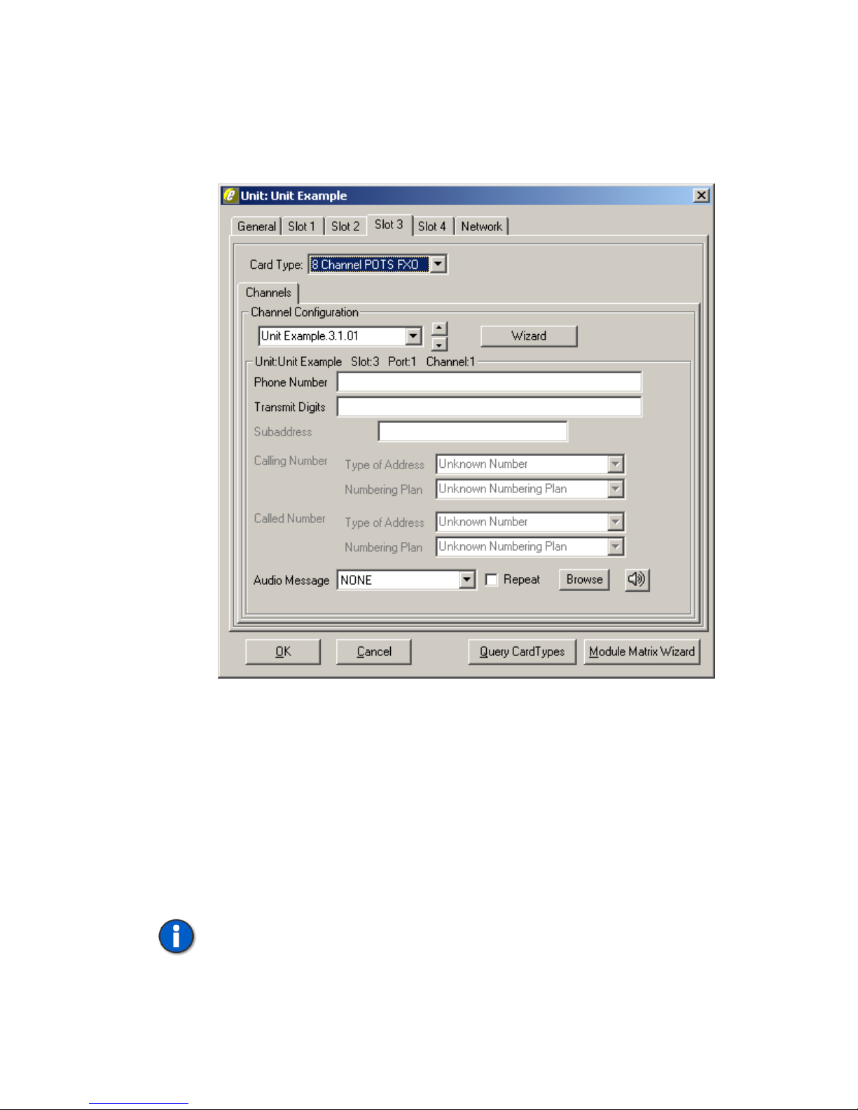
When the 8 Channel POTS FXO card type is chosen, only a Channels tab is
displayed. See Figure 19. These channels operate as Analog Loop Start FXO only.
TSP Edge User’s Manual
Figure 19. POTS FXO Card Type
Channels Tab
The Channels tab is where each channel can be assigned a Phone Number, Transmit
Digits (T1/E1 only) and Audio Message. The Channel Configuration field assigns the
channel an identification number (see “Channel Identification” on page 30).
The Subaddress, Calling Number, and Called Number fields are only available for
T1-PRI and E1-PRI card modes. For more information, see “Primary Rate ISDN
Software Modules (TSP-PRI and TSP-2PRI)” on page 87.
Note: For E1, only usable channels are listed (1-30). The 2 signaling channels
are not available.
40-400-00065, Rev. E
29
Page 40

TSP Edge User’s Manual
Channel Identification
The channel identification number is based on the name the unit was given, the slot
number the module is in, the port (each physical connector on a card is considered a
port and is numbered on the card), and the logical channel (1-24 on a T1, 1-30 on an
E1, 1-2 on an 8 Channel POTS and only 1 on a 4 Channel POTS). Each "port" can
have one or more "channels". For instance, each T1 port has 24 channels. On an 8
channel POTS module, each of the four ports has two channels (i.e., each connector
has two analog phone lines).
The assignment method is displayed in Figure 20.
Unit Example . 3 . 1 . 01
Unit Name
Channel Number
Port NumberSlot Number
Figure 20. Channel Identification
Note the numbering scheme by clicking the arrow under Channel Configuration on a
POTS Unit screen. The channel displayed in Figure 20 is “Unit Example .3.1.01”.
The name assigned to the Edge is “Unit Example” with .3 being the third slot in the
Edge. The .1 is the first port of four on the POTS module. The .01 is for the first
channel of two on each port of the 8 Channel POTS module. Note that the breakdown
for the channel assignment is displayed just beneath the Channel Configuration box
on the POTS screen.
All the parameters available for the T1/E1 cards under the Channel Configuration are
identical on the 4 and 8 Channel POTS Card Type screens, except for Transmit
Digits, which is only available on T1/E1.
Phone Number
The Phone Number is the telephone number assigned (up to 40 digits) to a channel
that will be dialed by another channel to call to that channel. This only applies to the
Dialed control sets.
Transmit Digits
The Transmit Digits are the DTMF digits (up to 40 digits) that the Edge sends
digitally via common channel for PRI calls or in-band when a call is placed to a
T1/E1 Wink Start, Delay Dial, Immediate Dial, FXS, or Q.421 channel. This provides
routing information as in DNIS operation for the equipment under test, if needed.
Note: Only in-band DTMF signaling is available. R1 and R2, MF signaling
is currently not supported by the Edge.
The format used for transmitting ANI and DNIS varies depending on how the
equipment under test is programmed. A * can be used in the Transmit Digits field to
40-400-00065, Rev. E
30
Page 41

TSP Edge User’s Manual
provide a separator between the ANI and DNIS. A # can be used as the terminator.
The following are two possible scenarios:
ANI*DNIS# or DNIS*ANI#
Where the total number of characters is 40 or less.
Also, other variations are possible. Refer to the manual of the equipment under test
for more information.
Audio Message
The last option for Channel Configuration is Audio Message. Here you can choose an
audio file to be played during a call simulation.
The default for Audio Message is NONE. An audio file can be chosen by clicking the
Browse button and choosing the preferred file. The speaker button plays the audio file
chosen. If you wish to have the message played continuously during the call, click the
Repeat box to enable it, otherwise the message is played only once.
Audio Messages must be created and stored in mu-law or a-law encoded, 8 bit Wave
file format, and are stored in the PC in the Audio folder. The Edge automatically
converts a Wave file between a-law and mu-law in order to transmit them in
accordance with the unit’s port configuration.
Messages that are less than 8 seconds in length, with a total combined length of 24
seconds or less, are downloaded into the Edge and stored in nonvolatile memory. If
any messages are longer than 8 seconds, or the combined length exceeds 24 seconds,
some messages will be streamed to the Edge in real-time over the network
connection.
Notes: To download or stream audio files, the Edge must have a network
connection and a valid IP address programmed.
Streaming audio files to the Edge in real-time may be affected by the number
of channels playing audio simultaneously, the speed of the PC streaming the
audio, and other network traffic.
40-400-00065, Rev. E
31
Page 42
TSP Edge User’s Manual
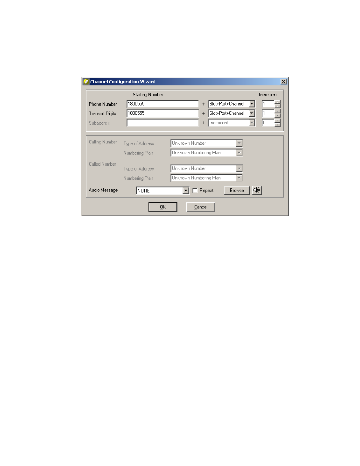
Channel Configuration Wizard
If you click the Wizard button, the Channel Configuration Wizard dialog box appears
(see Figure 21).
Figure 21. Channel Configuration Wizard
This dialog box can be used to automatically assign Phone Number, Transmit Digits,
and Audio Message for all the channels on that card at once. These fields are the
same as the ones under Channel Configuration on the Slot tab for the Unit screen and
can be configured either way.
For assigning Phone Number or Transmit Digits, numbers are assigned using the
value in the Starting Number field, modified in one of two ways. The
Slot+Port+Channel option assigns the last four digits according to the channel’s
location in the Edge. Selecting the Increment option enables the Increment field. Each
channel is given the Starting Number plus the Increment used. (i.e., Starting Number
12345678901 for Increment of 3. Channel 1- 12345678901, channel 2- 12345678904,
channel 3- 12345678907, channel 4- 12345678910, etc.)
The wizard assigns the Audio Message selection to all the channels on that module.
Click OK at the bottom of the Channel Configuration Wizard dialog box when
finished with the settings.
Once configurations are completed on the Unit screen, click OK. The configuration
information is automatically sent to the Edge.
40-400-00065, Rev. E
32
Page 43
Note: The error message “Installed card types do not match defined card
types” indicates a configuration mismatch between the physical modules in
the Edge and card types selected on the Unit screen. If this message occurs,
click OK, and open the Unit screen, and select the Edge to edit. Verify and
correct the settings. To avoid this error, it is recommended that you
automatically configure the Edge by using the Query Card Types button.
Module Configuration Summary
1. If using a T1/E1 module, select the Slot tab that corresponds to the
module’s location and select the appropriate card mode from the Card
Mode list. The T1 or E1 tab is used to set the parameters according to the
equipment being tested.
Note: T1-PRI and E1-PRI are available when optional software
module(s) are purchased. For more information, see “Primary Rate
ISDN Software Modules (TSP-PRI and TSP-2PRI)” on page 87.
2. If using T1-PRI or E1-PRI mode, a PRI tab appears. Set the appropriate
Switch Type and Simulation, which is the end the Edge will be simulating.
TSP Edge User’s Manual
Templates
Templates are used to define details of the channel protocols to be used for call
simulation. The basic protocol is set on the Type tab, timings for that protocol are set
on the Timings tab, and the signaling bit patterns used for the protocol are set on the
Signaling tab.
Select New on the Templates menu. A screen requesting to "Enter New Template
Name" is displayed. It is recommended that the template name reflect the protocol
being used. This makes it easier to distinguish what the protocol of the Template is on
the Control Set(s). After entering the template name, it is displayed in the Template
3. Configure the Channels tab for all the installed modules. Each channel can
be assigned a Phone Number (T1, E1 and POTS), Transmit Digits (i.e.,
ANI and DNIS for T1 and E1), and Audio Message (the network
connection must be established). For T1-PRI and E1-PRI, Subaddress,
Called Number and Calling Number features are also available. For more
information, see “Channels Tab” on page 29.
The Channel Configuration Wizard button can be used to assign values to
all the channels at once. For more information, see “Channel
Configuration Wizard” on page 32.
4. Click OK to exit the Unit screen.
The configuration information is sent to the Edge.
40-400-00065, Rev. E
33
Page 44
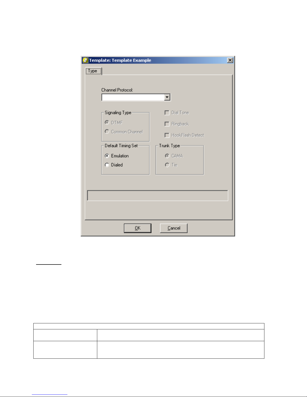
TSP Edge User’s Manual
dialog box title bar (see Figure 22). The Signaling tab only appears once a Channel
Protocol using bit signaling is chosen.
Figure 22. Template Type Tab
Type Tab
Channel Protocols
A template has several Channel Protocols available as listed in the Channel Protocols
field (see Table 2). Click the Channel Protocol arrow to choose an option (scroll
down to see all options). Once a template is assigned to a control set, the channel type
cannot be changed (for more information, see “Control Sets” on page 40).
Table 2. Channel Protocols
ANALOG PROTOCOLS
Analog Loop Start FXS
Analog Loop Start FXO
40-400-00065, Rev. E
34
This is used only with 4 or 8 Channel POTS FXS modules. The channel
provides battery, ground and ringing to the terminating set.
This is used only with 8 Channel POTS FXO modules. The channel
detects ringing, provides an off-hook or on-hook state and transmit
DTMF.
Page 45
E1 ITU Q.421
T1/E1 Loop Start FXO
T1/E1 Loop Start FXS
T1/E1 Ground Start FX0
T1/E1 Ground Start FXS
T1/E1 Immediate Dial
T1/E1 Delay Dial
T1/E1 Wink Start
T1/E1 Clear Channel
T1 Primary Rate (CPE)
T1 Primary Rate
(Network)
E1 Primary Rate (CPE)
E1 Primary Rate
(Network)
TSP Edge User’s Manual
DIGITAL PROTOCOLS
Used only when equipment under test is set-up for E1 CAS operation.
This is an ITU-T signaling standard for E1 channel associated signaling.
Used when the equipment under test is configured for foreign exchange
operation and is functioning as the office. The Edge interfaces with the
equipment under test using loop start signaling on the specific channel of
the T1/E1.
Used when the equipment under test is configured for foreign exchange
operation and is functioning as the station. The Edge interfaces with the
equipment under test using loop start signaling on the specific channel of
the T1/E1.
Used when the equipment under test is configured for foreign exchange
operation and is functioning as the office. The Edge interfaces with the
equipment under test using ground start signaling on the specific
channel of the T1/E1.
Used when the equipment under test is configured for foreign exchange
operation and is functioning as the station. The Edge interfaces with the
equipment under test using ground start signaling on the specific
channel of the T1/E1.
This is used when the Edge interfaces with the equipment under test as
an Immediate Dial circuit on the channel of the T1/E1. The signaling bits
use Immediate Dial protocol.
This is used when the Edge interfaces with the equipment under test as
a Delay Dial circuit on the channel of the T1/E1. The signaling bits use
Delay Dial protocol.
This is used when the Edge interfaces with the equipment under test as
an Wink Start circuit on the channel of the T1/E1. The signaling bits use
Wink Start protocol.
This is used when the Edge interfaces with the equipment under test to
cross-connect two T1/E1 channels to provide for clear channel
operation. The T1 should be configured for ESF, with B8ZS line coding.
E1 should be configured for HDB3 line coding.
This is used when the Edge simulates the CPE end and interfaces with
equipment under test configured for PRI. To select a T1 Primary Rate
(CPE) template for a control set and then assign channels, at least one
unit’s slot card mode must be T1-PRI with the PRI tab simulation setting
as CPE.
This is used when the Edge simulates the network and interfaces with
equipment under test configured for PRI. To select a T1 Primary Rate
(Network) template for a control set and then assign channels, at least
one unit’s slot card mode must be T1-PRI with the PRI tab simulation
setting as Network.
This is used when the Edge simulates the CPE end and interfaces with
the equipment under test configured for PRI. To select an E1 Primary
Rate (CPE) template for a control set and then assign channels, at least
one unit’s slot card mode must be E1-PRI with the PRI tab simulation
setting as CPE.
This is used when the Edge simulates the network and interfaces with
equipment under test configured for PRI. To select an E1 Primary Rate
(Network) template for a control set and then assign channels, at least
one unit’s slot card mode must be E1-PRI with the PRI tab simulation
setting as Network.
40-400-00065, Rev. E
35
Page 46

TSP Edge User’s Manual
Signaling Type
This option cannot be changed. This may be enabled for future enhancements.
Default Timings Set
The choices of Emulation and Dialed are used in conjunction with the Controls Set
type chosen. Emulation is the default and is used in all but Dialed Control Sets. When
using Dialed Control Sets, choose the Dialed Default Timing Set. The Timings
default values are set differently to accommodate for the call progress differences in
the Control Sets. For more information, see “Control Sets” on page 40.
Dial Tone
The Dial Tone feature only applies to FXS protocols. The Edge defaults to providing
Dial Tone on the channel. You can disable Dial Tone by clearing the Dial Tone check
box.
Ringback
The Ringback feature applies to FXS, Delay Dial, Immediate Dial, Wink Start, E1
ITU Q.421, and PRI Network protocols. The Edge defaults to providing ringback on
the channel. You can disable Ringback by clearing the Ringback check box.
Hook Flash Detect
This option allows detection of hook flash to perform transfers. It only allows
transfers between analog FXS lines in a dialed control set.
Trunk Type
This option gives the choice of Tie Trunk or CAMA for T1/E1 Wink Start, Delay
Dial, and Immediate Dial. Tie Trunk is for end-to-end signaling. CAMA operation is
where a signaling is done section by section.
Timings Tab
Timings are used to control the intervals of all the different parts of the call process
while the Edge is originating or terminating calls. The default times should be
appropriate for most testing.
There are three sections on the Timings screen:
• Timings in the Originating Calls section are used when the Edge is generating
• Timings in the Terminating Calls section are used when the Edge is receiving
calls to the equipment under test.
incoming calls from the equipment under test.
• Timings in the All Calls section apply to both incoming and outgoing calls.
See “Call Timings and Process Flowcharts” on page 125 for a detailed description of
each parameter.
40-400-00065, Rev. E
36
Page 47
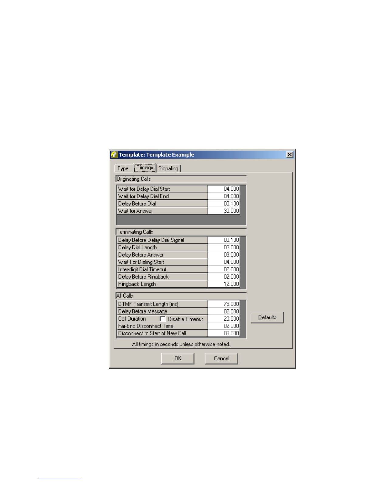
TSP Edge User’s Manual
Clicking anywhere on the line for a parameter highlights the value and displays
arrows, which allow you to change the timing value. If you click to the left of the
decimal point, the arrows change the numbers to the left of the decimal point. If you
click to the right of the decimal point, the arrows change the numbers to the right of
the decimal point. You may also enter the value directly using the keyboard.
The DTMF Transmit Length may be set between 50 and 200 milliseconds, in 12.5
millisecond increments. All other values may be set from 0 to 300 seconds, in 5
millisecond increments.
All timings are reset to default settings by clicking the Defaults button (see Figure
23).
40-400-00065, Rev. E
Figure 23.Template Timings Tab
37
Page 48
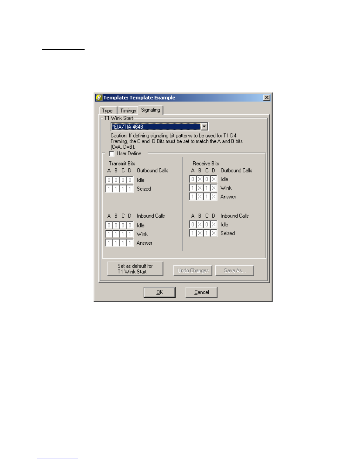
TSP Edge User’s Manual
Signaling Tab
The Signaling tab is used to modify the T1 and E1 bit states for the selected signaling
protocol (see Figure 24). These are the A & B bits for D4 (a.k.a. Superframe) and the
A, B, C & D bits for ESF and E1 signaling. This gives the Edge the flexibility to
match the protocol of the equipment under test if using a different standard.
The first field is for using a predefined protocol and has *Factory Default listed. This
uses the bits states as defined by the standard for the Channel Protocol chosen on the
Type tab. Clicking the arrow lists equipment that Teltone Corporation has verified the
default bits states used during call progress. All predefined settings provided by
Teltone begin with a “*”. All others listed without the “*” will be those created by the
user.
User Define Field
The User Define field is checked if it is necessary to change the bit state parameters
to match the equipment under test. Once checked, it will become grayed out and the
predefined protocol field above will become blank. The Undo Changes and Save As
40-400-00065, Rev. E
38
Figure 24.Template Signaling Tab
Page 49

buttons become available at this point and the bit state Outbound (end initiating call)
and Inbound (end receiving the call) fields can be edited. A 1 or 0 can be entered into
these fields since signaling is done in a binary form. An X is used for a Receive Bit
when that signaling bit is not used.
Information on the bit states for the equipment being tested by the Edge should be
obtained from the manual, vendor or technical support of that product.
Notes: For T1, when using D4 framing, the bit fields are in ABAB format and
the C and D bits must match the A and B bit fields. This is because D4 does not
employ C and D bits and will cause signaling problems.
For E1, the C and D bits must be set for 0 and 1 respectively. Otherwise,
synchronization problems will occur.
Set as Default for (Channel Protocol) Button
The Set as Default for (channel protocol) button allows the user to set a predefined
protocol other than the factory default to be used when a Channel Protocol is chosen
on the Type tab. This allows the assignment of the channel protocol without having to
go to the Signaling tab each time.
TSP Edge User’s Manual
Undo Changes Button
The Undo Changes button sets the signaling back to the predefined protocol listed
before checking the User Define button. The same thing can be done by clicking the
down arrow for the predefined protocols and choosing one.
Save As Button
The Save As… button is used to assign a name to the signaling protocol states
defined in the User Define section. Once saved, the name will be available in the
predefined protocols list when clicking the down arrow.
Template Configuration Summary
1. Create templates to configure the channel protocols based on the modules
being used (i.e., Analog Loop Start templates for POTS, and T1 Wink
Start template for T1/E1 modules). A template is associated with the
channels to be tested when a control set is created. To create a template,
select New on the Templates menu.
2. Click the Channel Protocol arrow for a list of available protocols. For
more information about the protocols, see “Type Tab” on page 34. Analog
Loop Start templates are only used for the POTS modules. Start by using
the defaults for all the fields on the template.
40-400-00065, Rev. E
39
Page 50
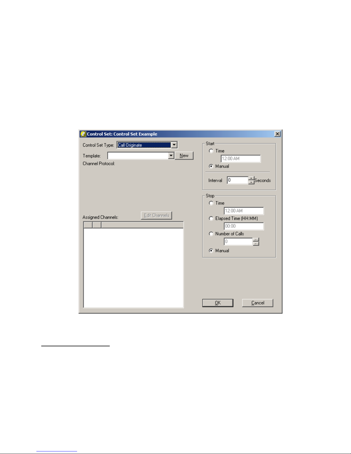
TSP Edge User’s Manual
Control Sets
A control set tells the Edge how to function. Control sets are used to set up the type of
test the Edge will perform, assign the template(s) to be used, the channels to be tested,
and the protocol used for the channels. Certain tests can be set up to start and
complete either manually or automatically. Multiple control sets in a single Edge
provide for greater flexibility.
To create a new control set, select New on the Control Sets menu. The New Control
Set Name dialog box is displayed. Enter a name and click OK. The Control Set dialog
box is displayed (see Figure 25).
Control Set Type Field
The Control Set Type field is used to configure the mode the Edge will be in. Note
the Control Set Type defaults to Call Originate.
Call Originate Control Set Type
The Call Originate Control Set is used when the Edge will generate calls to the device
under test. The Edge will place a call on each channel, sending the Transmit Digits (if
defined) and playing an audio file after the call is connected (if an audio file is
40-400-00065, Rev. E
40
Figure 25. Control Set
Page 51
assigned to the channel). For the Call Originate Control Set Type, one Template field
is displayed. All Channel Protocols except for T1/E1 Clear Channel can be used for
this Control Set Type.
Call Terminate Control Set Type
The Call Terminate Control Set is used when the Edge will receive calls generated by
the device under test. The Edge will answer calls placed into it, then play an audio file
after the call is connected (if an audio file is assigned to the channel). For the Call
Terminate Control Set Type, one template field is displayed. All Channel Protocols
except for T1/E1 Clear Channel can be used for this Control Set Type.
End-to-End Control Sets
The End-to-End Control Set is used when calls are placed by one connected device
through the Edge to another connected device.
There are four types of End-to-End Control Sets: Dialed, Switch Emulation,
Channel Bank, and DS0 to DS0. With these operations the Edge passes traffic
through from one channel to another.
TSP Edge User’s Manual
Dialed Control Set - A Dialed control set acts as a PBX or Central Office switch.
Any channel within a Dialed control set can route a call to any other channel within
the same control set when it receives the telephone number assigned on the Channels
tab of the Unit screen.
Dialed control sets have the option to use up to two different Templates, allowing
Analog POTS channels and T1/E1 channels, or two different T1/E1 channel types, to
be combined in the same control set.
Note: When using the Dialed control set type, the Templates used need to use
the Dialed Default Timing Set on the Type tab. This ensures proper operation
when making a call.
Switch Emulation Control Set - Switch emulation control sets act similar to a
Dialed control set, except that instead of looking at the digits that are dialed, the
channels to be connected are pre-defined in the control set. This connection is
scripted and occurs automatically once a call is initiated by an off-hook or a seizure.
Note: Calls routings are static and are not routed by telephone number, but by
channel assignment in the Control Set. For more information, see “Channel
Assignments” on page 43. Also, call progress including dial tone and ringback
is done by a scripted timing rather than action done by dialing a number.
Channel Bank Control Set - Connects a T1/E1 channel to a POTS channel and
passes the signaling straight through. For Channel Bank operation, an Analog Loop
40-400-00065, Rev. E
41
Page 52
TSP Edge User’s Manual
Start channel can be connected to a T1/E1 FXO Loop Start channel or a T1/E1 Clear
Channel.
Channel Bank Simulation - For T1/E1 FXO Loop Start to the Analog Loop Start, the
POTS channel connects with the T1/E1 FXO Loop Start channel and will pass voice
traffic. This simulates a channel bank.
The T1/E1 Clear Channel to Analog Loop Start setup will allow a channel bank setup
between a POTS port and a T1/E1 clear channel. This allows the Edge to connect to a
T1 port on an SS7 system to provide voice traffic. An external control is required to
provide for SS7 signaling on the equipment under test when establishing a call.
In this configuration, when the POTS phone goes off-hook, the audio path will be
connected to the T1 channel. When the POTS phone goes on-hook the T1 channel
will receive silence. Since the T1 channel is clear channel, there will be no signaling
between the two channels.
Note: Ringing to the POTS port is not available due to the absence of
signaling in T1 Clear Channel operation.
DS0 to DS0 Control Set - Connects two channels together with no signaling. The
DS0 to DS0 Control Set only allows the use of a template created for T1/E1 Clear
Channel protocol. This can be done on a Single T1/E1 by connecting a channel to
another channel on the same T1/E1 or on the Dual T1/E1 module, connecting a
channel from the Port 1 T1/E1 to a channel on the Port 2.
Note: Fractional T1 and T1 data is not supported. Data is only supported at the
DS0 64K channel level to another 64K channel.
User Script Control Sets
For information about User Script control sets, see “Advanced Test Scripting
Software Module (TSP-ATS)” on page 97.
Template Field
The Template list gives the choices of the templates that have been created which can
be used for the Control Set Type chosen. A new template can also be created from
this screen by clicking New (see “Templates” on page 33). Either select a previously
created template from the Template list or create a new template by clicking the New
button.
For End-to-End Control Sets, the Control Set screen shows two template fields
instead of one. This allows you to assign different templates to each of the two
channels that you are connecting, and allows combining T1/E1 and analog channels
within the same control set.
40-400-00065, Rev. E
42
Page 53
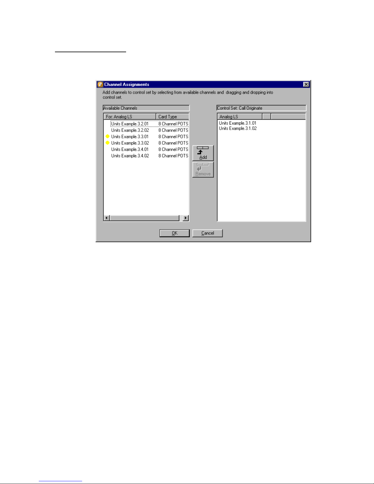
TSP Edge User’s Manual
Channel Assignments
To select the channels, click the Edit Channels button (see Figure 25). The Channel
Assignments screen appears (see Figure 26).
Figure 26. Channel Assignments (Analog)
The Channel Assignments screen displays the Available Channels to test for the
Control Set Type and Template chosen on the Control Set screen.
For example, assume that for an Analog LS Channel Type, the name “Analog LS”
was given to the template. Notice that in the Channel Assignment screen on the left
side under Available Channels, the template name, “Analog LS”, is displayed (see
Figure 26). Listed underneath are the channels that can be used for the selected
control set and template.
For another example, assume that the template was configured for T1 Wink Start
protocol and named “T1 Wink St” (see Figure 27). The left side under the Available
Channels has channels 1-24 for both T1s, and any of the channels can be chosen.
40-400-00065, Rev. E
43
Page 54
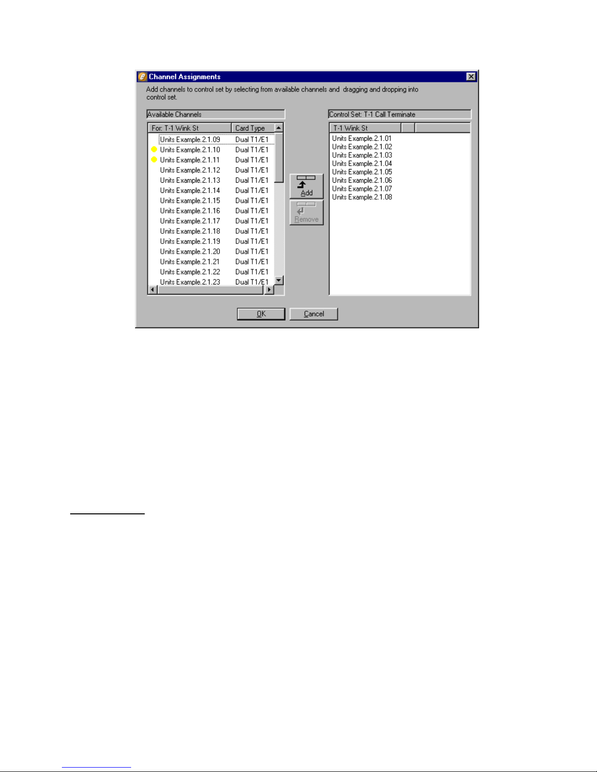
TSP Edge User’s Manual
Add/Remove Buttons
The channels to be tested are chosen by selecting the channel on the left side and
clicking the Add button or by dragging and dropping a channel to the right side of the
screen. To remove a channel on the right, select it and click the Remove button or
drag and drop it back to the left side of the screen. Multiple channels can be done
simultaneously by using the Shift or Control keys while selecting the channels. Click
OK once the channels have been chosen. This will take you back to the Control Set
screen (see Figure 25).
Start and Stop
The Start and Stop areas on the Control Set screen are only used in Call Originate
mode. This is used to control when the Edge will start making test calls, at what
interval (in seconds, if any) each call will be placed, and when to stop placing the
calls.
Start
For starting a simulation, the choices of Time and Manual are available. Selecting
Time enables a field to set a predefined time for the Edge to start.
Figure 27. Channel Assignments (T1 Channels)
To manually start the test, select Manual. Testing starts immediately once the Control
Set Enable button is clicked in the Edge configuration software main window.
40-400-00065, Rev. E
44
Page 55

TSP Edge User’s Manual
Interval
Interval is used to stagger the testing on the channels. Using the Interval delays the
calls to each channel (in seconds) starting with the first channel listed in the Assigned
Channels section. In the Interval box, type or select the number of seconds.
By leaving the interval set to 0 seconds (the default), all channels assigned to the
Control Set initiate calls simultaneously once the test begins.
Stop
For ending a simulation, the choices of Time, Elapsed Time, Number of Calls, and
Manual are available. Selecting Time enables a field to set a predefined time for the
Edge to stop testing. Selecting Elapsed Time enables a field to set the amount of time
(in hours and minutes) the test is to run once started. The Number of Calls option is
used to set a specific number of calls to be placed to each of the channels assigned.
Selecting Manual stops the test when the Control Set Enable button is disabled.
End-to-End Example
The control set for end-to-end operation is configured with two template fields. For
this example, we will use Switch Emulation with POTS and T1 Channels.
1. Go to Control Sets menu and choose New. Name the control set “End-to-
End Example” and click OK.
2. In the Control Set dialog box, select Switch Emulation for the Control
Set Type.
3. Create a new template by clicking the New button next to the first
Template field. Name the Template “Analog LS”. Choose Analog Loop
Start for the Channel Protocol and click OK.
4. Click New at the second Template field. Name the Template “T1 Wink
St”. Choose T1/E1 Wink Start for the Channel Protocol and click OK.
The names “Analog LS” and “T1 Wink St” appear in the Template fields in the
Control Set dialog box. See Figure 28.
40-400-00065, Rev. E
45
Page 56
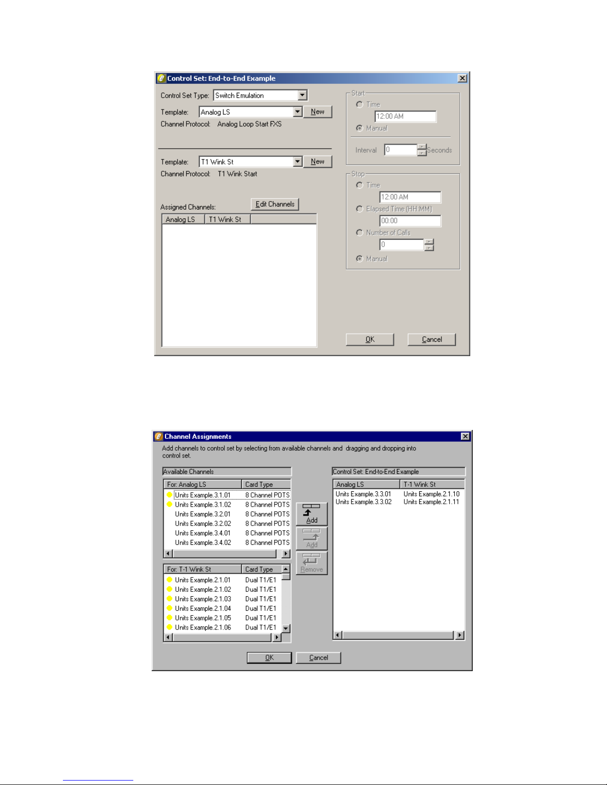
TSP Edge User’s Manual
Figure 28. End-to-End Control Set Example
5. Click the Edit Channels button.
The Channel Assignments dialog box appears. See Figure 29.
40-400-00065, Rev. E
46
Figure 29. Connecting Channels
Page 57
TSP Edge User’s Manual
In this example, channels are added under the “Analog LS” column by
choosing the Available Channels in the upper left box. These are the
POTS channels available for the simulation that will work with the Analog
Loop Start template. A channel can only be added to the second column
on the right (i.e., T1 Wink Start) when there is already an entry on the
same line in the first column (i.e., Analog LS). Use the channels in the box
on lower left with the T1 card type for the “T1 Wink St” column. The
pairs of channels on each line connect when a call is initiated from either
end.
Yellow dots next to any channels indicate that these channels have already
been assigned to a previously created Control Set. These channels can be
used for this control set, but are then no longer be assigned to the previous
control set.
Click OK when done assigning channels.
6. Click OK in the Control Set dialog box.
The main window appears with an End-to-End Example button under Control Set
Enables.
7. Click the End-to-End Example button.
The control set is activated allowing calls to take place. The equipment under test
at both ends initiate the traffic, and the Edge is passive in this example.
Control Set Configuration Summary
1. Create a new control set by selecting New on the Control Sets menu.
2. Select a Control Set Type.
3. Assign template(s) to be used with the channels tested. Select a template
in the Template field. Call Originate and Call Terminate have one
Template field while all other control sets have two fields.
4. Assign channels by clicking the Edit Channels button. A Channel
Assignment screen appears and the Available Channels are listed on the
left side of the screen. Select the channels to be tested by moving them
from the left side to the right side. Click OK.
Note: The Switch Emulation, Channel Bank, and DS0 to DS0
control set types require the channels to be paired side-by-side on
the right side of the screen. The channel initiating the call will
automatically be connected to the channel it is paired with.
5. Program the Start and Stop times, if applicable.
6. Click OK.
The main window is displayed.
7. Run your simulation by clicking its Control Set Enables button in the main
window.
40-400-00065, Rev. E
47
Page 58
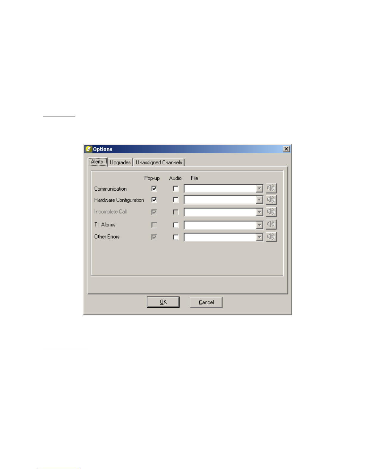
TSP Edge User’s Manual
Options
The Options dialog box allows you to set up alerting, enter license codes for
upgrading the Edge, and change the default idle state for unassigned channels.
Select Options on the View menu.
Alerts Tab
When an error or alarm status on any connected unit occurs, the Edge configuration
software can display a pop-up window and/or play a sound file (see Figure 30).
Upgrades Tab
The Upgrades tab (see Figure 31) is where you enter license codes for:
• Enabling additional purchased software modules
• Setting warranty information (to view current warranty expiration date, see
“Viewing Unit Information” on page 22)
40-400-00065, Rev. E
48
Figure 30. Alerts Tab
Page 59
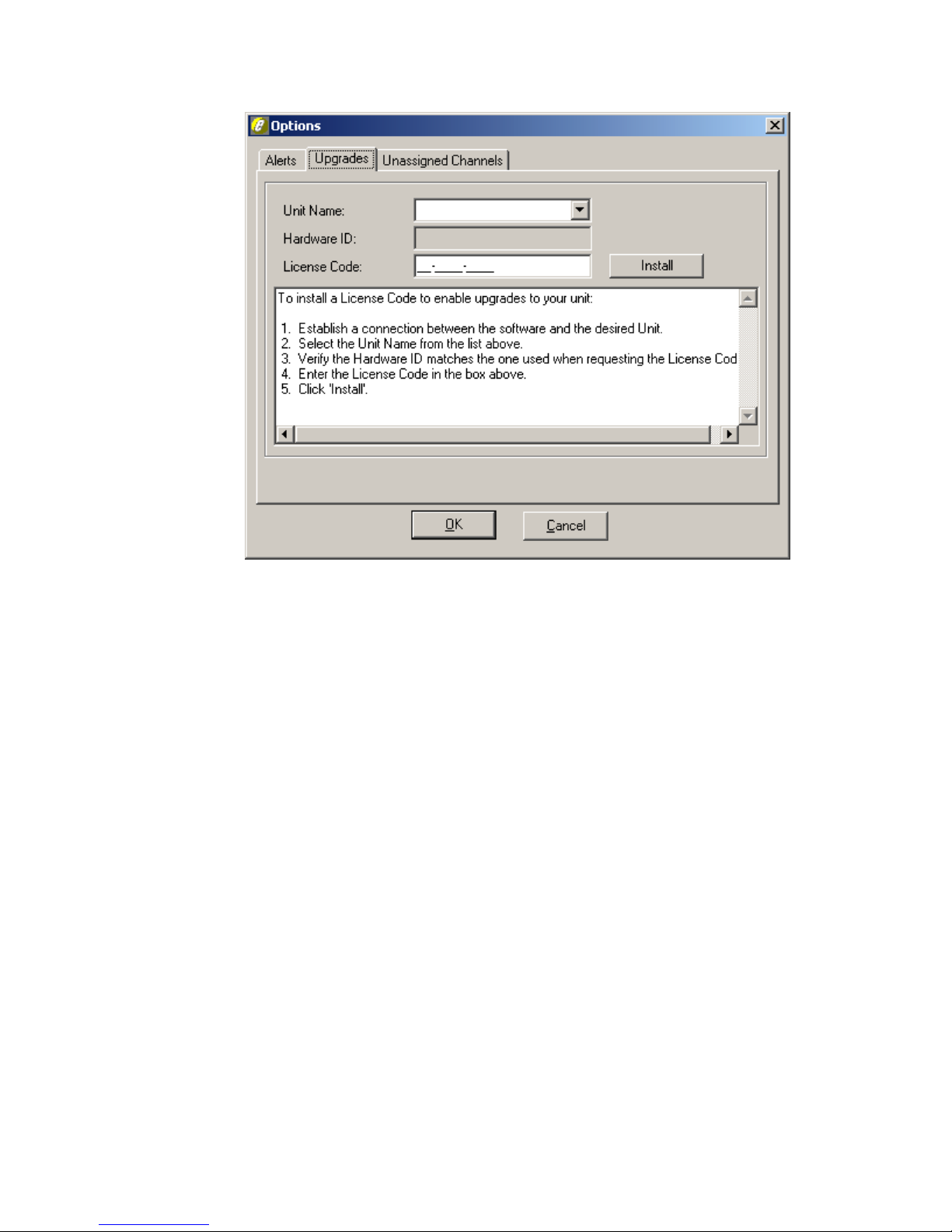
TSP Edge User’s Manual
Figure 31. Upgrades Tab
Before contacting Teltone to purchase an upgrade, please have the following
available:
• The unit’s hardware ID (to view hardware ID, see “Viewing Unit
Information” on page 22)
• The unit’s current license code (to view license code, see “Viewing Unit
Information” on page 22)
• The unit’s serial number (on the bottom of the unit)
• Your name and title
• Your company name, address, and telephone number
• Your email address (this allows us to quickly send you your license code)
Once you have received a license code from Teltone, select Options on the View
menu. Then select the Upgrades tab, select the unit name in the Unit Name list, enter
the code, and click the Install button.
License codes need to be installed only once and are stored permanently in the Edge’s
memory. Once a license code is installed, the Edge can be used with any PC.
40-400-00065, Rev. E
49
Page 60

TSP Edge User’s Manual
Unassigned Channels Tab
The Unassigned Channels tab (see Figure 32) is used to define the default signaling
state for T1 and E1 channels that have not been assigned to any control set, and
therefore are not associated with any template.
These signaling states are used as the defaults when selecting a new card mode in the
Unit screen for an Edge and may be overridden on a per-unit basis (see “T1 Card
Mode” on page 24 and “E1 Card Mode” on page 26).
You can select an idle signaling state associated with a particular protocol or define
the actual bit pattern directly.
Figure 32. Setting the Default Idle State for Unassigned Channels
40-400-00065, Rev. E
50
Page 61
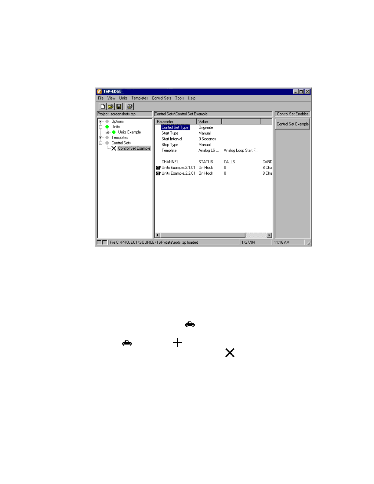
EXECUTING AND VIEWING SIMULATIONS
Executing a Simulation
Figure 33 shows a Control Set Enable button with the name “Control Set Example”.
TSP Edge User’s Manual
Figure 33. Control Set Information
When expanding the display tree for Control Sets and highlighting the name of the
Control Set, a list of the Parameters and Values are displayed in the information
section. See Figure 33. The same can also be done for all the other components on the
display tree.
A simulation is started by clicking the Control Set Enable button. The button appears
depressed when enabled and a small (running) icon appears next to the Control
Set name in the tree display (see “Icons” on page 16). Upon completion of a timed
simulation, the changes to a (finished). Manually stopping the simulation by
clicking the Control Set Enable button, causes the to re-appear next to the control
set after all the assigned channels return to an idle state. See Figure 34.
40-400-00065, Rev. E
51
Page 62
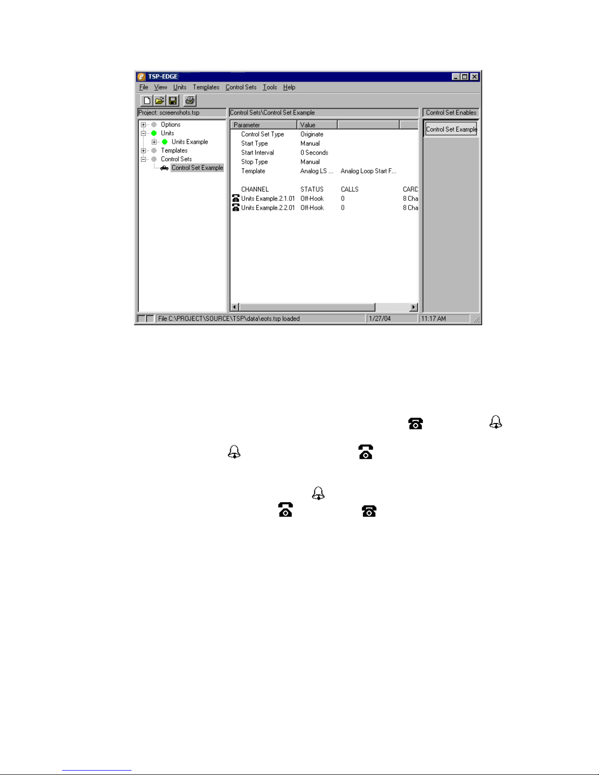
TSP Edge User’s Manual
Since the Control Set in Figure 33 and Figure 34 was configured for Manual Start and
Stop, the test calls start immediately and do not stop until the Control Set Enables
button is clicked a second time.
For POTS FXS channels the status of the channel changes from (on-hook) to
(ringing) to indicate a ringing state. Once the Edge recognizes an off-hook from the
equipment under test, the (ringing) changes to an (off-hook). See Figure 34.
This is the state of the equipment under test.
On T1/E1 Wink Start operation, there is no (ringing) or Ringing Status due to the
nature of the protocol operation. An (off-hook) or (on-hook) from the
equipment under test is the only indication.
Event Log
An event log is created for all events and calls related to the Edge. Various filters can
be turned on to eliminate conditions that you may not want to view.
To access the Event Log, select Event Log on the View menu. You then have two
options: Open, which opens the event log, and Clear, which allows you to delete the
contents of the event log.
Figure 34. Call Status
There are two views on the Event Log (see Figure 35).
40-400-00065, Rev. E
52
Page 63
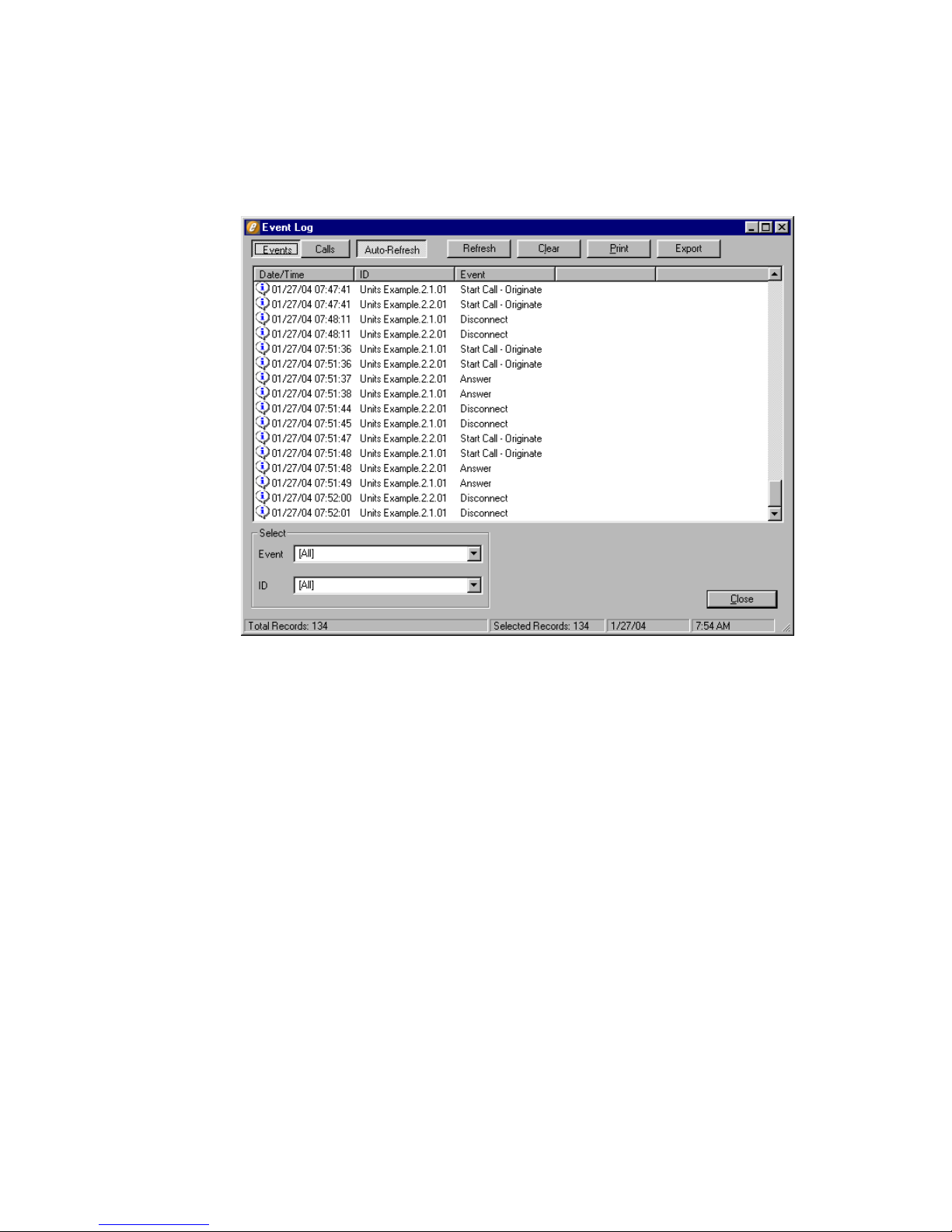
TSP Edge User’s Manual
• The Events view, shows all occurrences of any change in state on the Edge
and on all calls.
• The Calls view, shows call information only.
Figure 35. Events View on Event Log
Enabling Auto-Refresh initiates constant updates of the Event Log as changes occur.
Refresh is used when Auto-Refresh is off, which causes the log to update only when
the Refresh button is clicked.
Clear is used to delete all information stored in both the Events and Calls log and
starts the log with a clean slate.
Print allows printing of the current view of the log file.
Export allows saving the current view of the event log as a comma-delimited text file.
The bottom of the screen has a Select section where filters can be used to display
specific Events and/or specific IDs of the Edge system.
The Event filter allows viewing specific events or types of events.
The ID filter allows viewing of events for a specific unit or channel.
The Events view shows the date and time of the occurrence, the ID of the specific
unit or channel and what Event actually occurred.
40-400-00065, Rev. E
53
Page 64
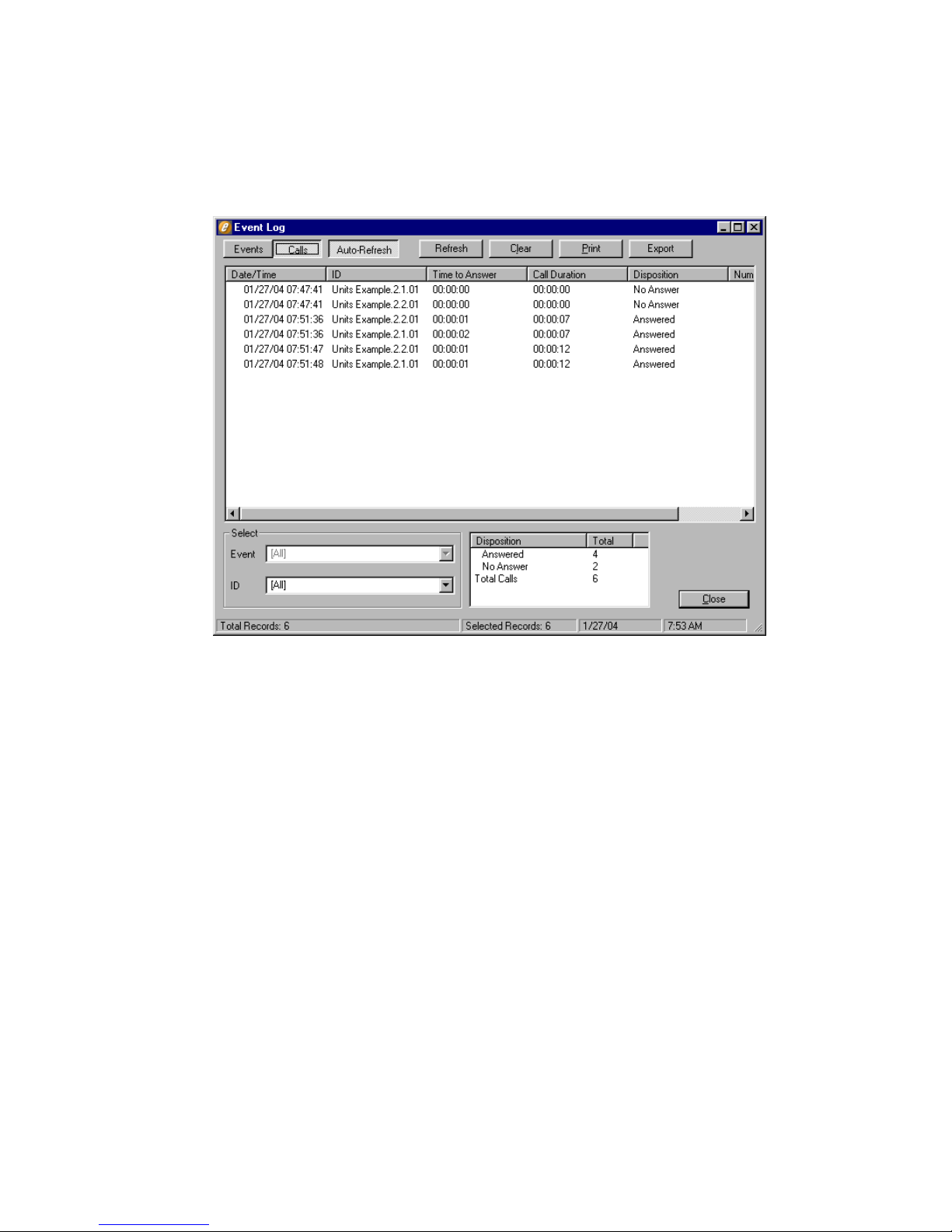
TSP Edge User’s Manual
The Calls view only shows the calls that have taken place on the channels that have
been running tests (see Figure 36). This view shows the date/time and ID plus the
Time to Answer, Call Duration and Disposition, indicating if the call was answered or
not.
Figure 36. Calls View on Event Log
When viewing Calls, a Summary box displays the dispositions and total number of all
calls on the channels selected in the Select field.
40-400-00065, Rev. E
54
Page 65
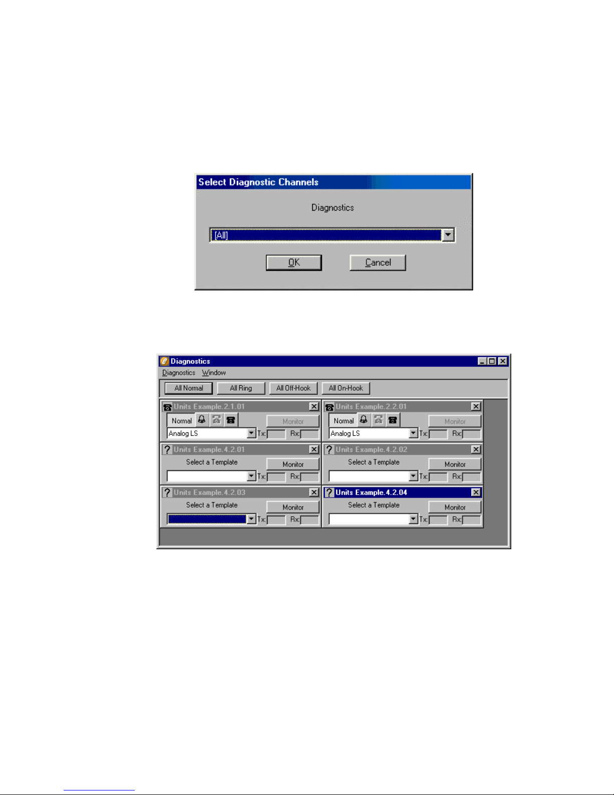
Diagnostics
Selecting Diagnostics on the Tools menu opens the Diagnostics window and a Select
Diagnostic Channels dialog box overlaid on top. See Figure 37. Click the arrow and a
list of channels is displayed. Scroll to select a specific channel. Selecting All will
bring up every channel on the Edge including the ones not in use. It is recommended
to choose a specific channel or choose by the Control Set name.
Figure 38 shows how channels are displayed. A box represents each selected channel.
TSP Edge User’s Manual
Figure 37. Select Diagnostic Channels Screen
Channels can be viewed in any combination. To add other channels, select View
Channel on the Diagnostics menu. To close a specific channel, click the Close button
in the title bar for the channel. To close all the channels, select Close All on the
Diagnostics menu. The Window menu controls the way the channels are arranged.
The icon in a channel’s title bar indicates an on-hook or off-hook condition from the
equipment under test.
40-400-00065, Rev. E
Figure 38. Diagnostics Window
55
Page 66
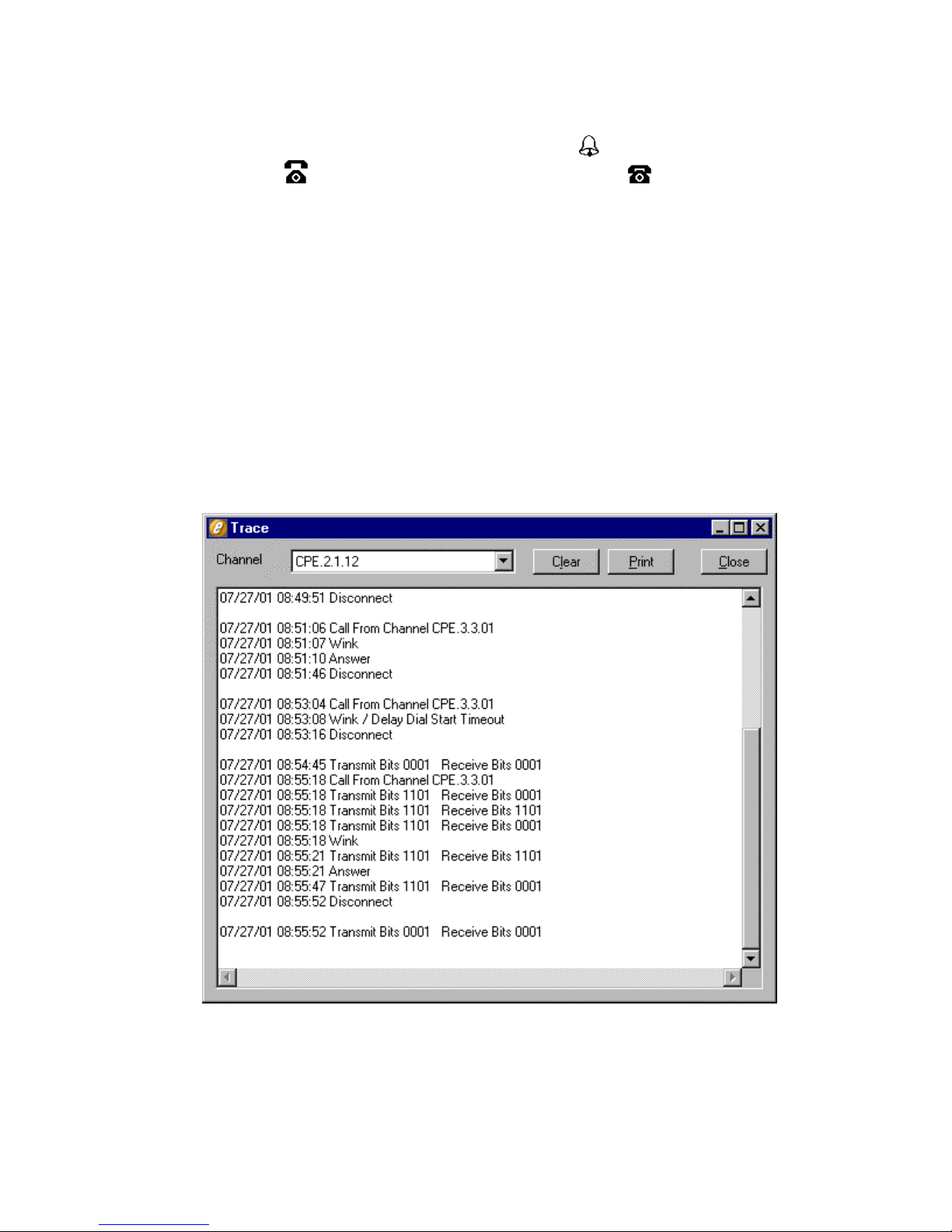
TSP Edge User’s Manual
A channel can be placed in a certain signaling state by clicking the appropriate button
in the channel’s box. Ringing is forced by clicking the
by clicking the button. On-hook is forced by clicking the button. The Normal
button puts the channel back to normal operation. In addition, all channels can be
placed in a certain state by clicking the All Normal, All Ring, All Off-Hook, or All
On-Hook buttons.
To view the signaling bits states for T1/E1 channels, click the Monitor button for the
channel. For ESF framing and E1, the ABCD bit states are indicated. For D4 framing,
the bit states are indicated in ABAB format. Only one channel can be monitored at a
time.
To exit Diagnostics, select Exit on the Diagnostics menu.
Trace
The step by step call progress of a channel can be displayed with the Trace screen
(see Figure 39). This feature is helpful for troubleshooting problems on calls.
button. Off-hook is forced
Select Trace on the Tools menu. Choose the channel to be monitored from the
Channel list. The information will scroll as calls are made on the channel.
40-400-00065, Rev. E
56
Figure 39. Trace Screen
Page 67

TSP Edge User’s Manual
Note: To have the transmit and receive signaling bits visible in the Trace
screen, the same channel must be selected in the Diagnostics screen, and have
the Monitor button selected.
40-400-00065, Rev. E
57
Page 68

TSP Edge User’s Manual
TEST AUTOMATION INTERFACE
The TAI (Test Automation Interface) allows a user to create an external program to
control one or more Edge units through links to the Edge configuration software. This
is used for the test and development environment with control software written in
TCL or LabView, or any programming language that is capable of DDE (Dynamic
Data Exchange) or TCP (Transmission Control Protocol) connections.
The TAI feature allows a user’s program to load preconfigured project files, start and
stop tasks (control sets), receive event messages, and access diagnostic and trace
(displays extended PRI event messages) functions.
Note: Sample programs that demonstrate the TAI functions are included in the
TAI folder with the Edge software.
Important: TAI features require using version 2.6 or greater of the Edge
software.
Basic Operation
Project files must be created using the Edge configuration software prior to using the
TAI functionality. The TAI interface does not allow for the editing of projects.
The Edge configuration software acts as a driver for the TAI functions. When using
the TAI functionality, the Edge program must be running on a PC that has
connectivity (either serial or network) to the Edge units being controlled.
Access to the TAI functions of the Edge configuration software can be done from a
program using DDE or TCP links, either on the same PC that is running the Edge
configuration software, or on another PC across a network. Only one connection at a
time is allowed.
40-400-00065, Rev. E
58
Page 69

TSP Edge User’s Manual
Communicating with Edge Configuration Software Using DDE
Sending
DDE commands are sent to the Edge configuration software using a DDE execute
command. DDE execute commands require the following three items:
Service: The service for all Edge commands is “Telecom Simulation
Platform”
Topic: The topic for all Edge commands is “link”
Data: The data for the Edge commands are the commands and
parameters as described in the following command
descriptions.
For example, to set a channel into a ringing diagnostic state the command would be:
dde execute {Telecom Simulation Platform} link SETDIAGNOSTIC,test.2.1.01,1
The exact command format may vary depending upon the actual programming
language used.
Retrieving
Retrieving data from the Edge configuration software through DDE uses a DDE
request. DDE requests require the following items:
After sending any command to the Edge configuration software, a request should be
sent to the appropriate DDE items to retrieve the results of the command.
For example, to receive the response from a command, the command would be:
dde request {Telecom Simulation Platform} link TSPData
The exact command format may vary depending upon the actual programming
language used.
Service: The service for all Edge requests is “Telecom Simulation
Platform”
Topic: The topic for all Edge requests is “link”
Item: There are three different item parameters used for the Edge.
These items are TSPData, TSPAlerts and TSPEvents. Usage of
these three items is explained in the following command
descriptions.
40-400-00065, Rev. E
59
Page 70

TSP Edge User’s Manual
Communicating with Edge Configuration Software Using TCP
To communicate with the Edge configuration software using TCP, an application
must request three socket connections from the Edge configuration software. All
requests are to the IP address of the PC that is running the Edge configuration
software, and are sent to the same port (default 3474). The first socket requested will
become socket1, the second socket2 and the third socket3. All commands to the Edge
configuration software are sent on socket1. Data returned from the Edge configuration
software is sent as described in the following command descriptions.
Since the socket connections are assigned in the order that they are requested, in the
event that any connection fails, all three must be closed and then re-established.
For example, to set a channel into a ringing diagnostic state, the command would be:
puts $socket1 SETDIAGNOSTIC,test.2.1.01,1
The exact command format may vary depending upon the actual programming
language used.
40-400-00065, Rev. E
60
Page 71

Commands
TSP Edge User’s Manual
GETMESSAGES
Format
GETMESSAGES, mode
Description
Retrieves events and warning messages
Parameter
DDE Returns
mode
0 Clears buffers
1 Retrieves messages
Item TSPData
OK Command accepted
Error Invalid parameter
Item TSPAlerts
List of warning messages. Messages delimited by “~”.
Item TSPEvents
List of events. Events delimited by linefeed.
TCP Returns
Socket1
OK Command accepted
Error Invalid parameter
Socket2
List of warning messages. Messages delimited by “~”.
Socket3
List of events. Events delimited by linefeed.
Notes
When using the DDE link, events and warning messages are buffered and sent when
polled by the getmessages command.
The getmessages command is not required when using the TCP link. Events and
warning messages are sent on sockets 2 and 3 automatically when they occur and are
not buffered.
40-400-00065, Rev. E
61
Page 72

TSP Edge User’s Manual
GETSTATUS
Format
GETSTATUS
Description
Retrieves status items.
DDE Returns
Item TSPData
Returns a list containing one or more of the following as
appropriate, delimited with linefeeds:
FILE,filename
Filename is the name of the current project file
UNIT,unitname,connectstatus
Unitname
name of an Edge unit defined in the current
project file.
Connectstatus
0 if connection to Edge is broken.
1 if connection to Edge is OK.
T1ALARMS,portname,alarms
Portname
t1/e1 port (unitname.slot.port)
Alarms
0 no alarms
1 Clock Sync
2 Red Alarm
3 Clock Sync & Red Alarm
TASK,taskname,enabled,runstatus
Taskname
task (control set) name
Enabled
0 task (control set) disabled
1 task (control set) enabled
runstatus
0 idle
1 channels still active
TCP Returns
Socket1
Same data as DDE link item TSPData
40-400-00065, Rev. E
62
Page 73

TSP Edge User’s Manual
INITIALIZE
Format
INITIALIZE,unitname
Description
Initializes an Edge unit
Parameter
DDE Returns
TCP Returns
unitname
Name of Edge unit to initialize
Item TSPData
Working Command accepted, initializing unit
Error Invalid parameter
Complete Initialization complete
Socket1
Same data as DDE link item TSPData
Notes
The working response is sent immediately after the command is received, and before
the initialization of the unit. The complete is sent when the initialization of the Edge
is completed.
If communicating via DDE, and the Working response is received, the user should
repeat the DDE request until the Complete response is received.
40-400-00065, Rev. E
63
Page 74

TSP Edge User’s Manual
LISTCARDS
Format
LISTCARDS,unitname
Description
Lists what cards are installed in an Edge unit
Parameter
DDE Returns
TCP Returns
unitname
Name of Edge unit
Item TSPData
Error Invalid parameter
Cardnames List of card types, one per slot, delimited with linefeeds
Socket1
Same data as DDE link item TSPData
40-400-00065, Rev. E
64
Page 75

TSP Edge User’s Manual
LISTCHANNELS
Format
LISTCHANNELS,taskname
Description
Lists what channels are assigned to a task
Parameter
DDE Returns
TCP Returns
taskname
Name of task (control set)
Item TSPData
Error Invalid parameter
Channelnames
List of channels (unitname.slot.port.channel) delimited
with linefeeds
Socket1
Same data as DDE link item TSPData
40-400-00065, Rev. E
65
Page 76

TSP Edge User’s Manual
LISTFILES
Format
LISTFILES
Description
Lists the project files that are in the data subdirectory
DDE Returns
TCP Returns
Item TSPData
Filenames List of file names delimited with linefeeds
Socket1
Same data as DDE link item TSPData
40-400-00065, Rev. E
66
Page 77

TSP Edge User’s Manual
LISTTASKS
Format
LISTTASKS
Description
Lists the tasks (control sets) that have been loaded from the project file
DDE Returns
TCP Returns
Item TSPData
Tasks (control sets) names
List of task (control set) names delimited with linefeeds
Socket1
Same data as DDE link item TSPData
40-400-00065, Rev. E
67
Page 78

TSP Edge User’s Manual
LISTUNITS
Format
LISTUNITS
Description
Lists the Edge units that have been loaded from the project file.
DDE Returns
TCP Returns
Item TSPData
Edge unit names
List of Edge unit names delimited with linefeeds.
Socket1
Same data as DDE link item TSPData
40-400-00065, Rev. E
68
Page 79

TSP Edge User’s Manual
LOADFILE
Format
LOADFILE,filename
Description
Loads a project file
Parameter
DDE Returns
TCP Returns
filename
Name of project file to load. Filename must exist in the data
subdirectory of the Edge configuration software, or must contain
the full path, and must exist on the same PC as the Edge
configuration software.
Item TSPData
Working Command accepted, loading project file
Error Invalid parameter
Complete File load complete
Socket1
Same data as DDE link item TSPData
Notes
The working response is sent immediately after the command is received, and before
the file is loaded. The complete is sent when the file load is completed.
If communicating via DDE, and the Working response is received, the user should
repeat the DDE request until the Complete is received.
40-400-00065, Rev. E
69
Page 80

TSP Edge User’s Manual
RUNTASK
Format
RUNTASK,taskname,state
Description
Starts or stops a task (control set)
Parameters
DDE Returns
TCP Returns
taskname
Name of task (control set) to start or stop
state
0 or Stop Disable task (control set)
1 or Start Enable task (control set)
Item TSPData
OK Command accepted
Error Invalid parameter
Socket1
Same data as DDE link item TSPData
40-400-00065, Rev. E
70
Page 81

TSP Edge User’s Manual
SETDIAGNOSTIC
Format
SETDIAGNOSTIC,channelid,state
Description
Places a channel into a diagnostic state
Parameters
channelid
state
DDE Returns
Item TSPData
Name of channel (unitname.slot.port.channel)
0 Return channel to normal operation
1 Set channel to ringing state
2 Place channel Off hook
3 Place channel On hook
OK Command accepted
Error Invalid parameter
TCP Returns
Socket1
Same data as DDE link item TSPData
Notes
The channel must be assigned to a task (control set), and the state must be valid for
the protocol in use. Multiple channels may be set in diagnostic modes simultaneously.
40-400-00065, Rev. E
71
Page 82

TSP Edge User’s Manual
SETMONITOR
Format
SETMONITOR,channelid
Description
Enables monitoring of bit state changes on a channel.
Parameter
DDE Returns
TCP Returns
channelid
Name of channel (unitname.slot.port.channel)
Item TSPData
OK Command accepted
Error Invalid parameter
Socket1
Same data as DDE link item TSPData
Notes
The channel must be assigned to a task (control set). Only one channel can be
monitored at a time, setting a new channel will disable monitoring of any previously
assigned channel. Bit state changes are sent as events.
40-400-00065, Rev. E
72
Page 83

TSP Edge User’s Manual
SETPRIEVENTS
Format
SETPRIEVENTS,channelid
Description
Enables extended PRI event messages for a channel.
Parameter
DDE Returns
TCP Returns
channelid
Name of channel (unitname.slot.port.channel)
Item TSPData
OK Command accepted
Error Invalid parameter
Socket1
Same data as DDE link item TSPData
Notes
The channel must be assigned to a task (control set). Only one channel can be set to
display PRI events at a time, setting a new channel will disable the display of PRI
events on any previously assigned channel.
40-400-00065, Rev. E
73
Page 84

TSP Edge User’s Manual
Warning Messages
Format
Prompt^Mode^Type^Response
Description
Warning messages are sent from the Edge software to the user’s application. Because
the prompt may contain commas, a carat “^” is used to separate parameters, and
events are terminated with a linefeed character.
Parameters
Prompt
Text string of the warning message
Mode
These are the buttons which normally would have shown on the
pop-up message box.
0 OK
1 OK Cancel
2 Abort Retry Ignore
3 Yes No Cancel
4 Yes No
5 Retry Cancel
Type
Type of message.
0 NONE
1 Communication error
2 Hardware error
4 T1 alarm
5 Other
Response
Default response which was generated to this message.
1 OK
2 Cancel
3 Abort
4 Retry
5 Ignore
6 Yes
7 No
Notes
When running the Edge configuration software, warning messages normally appear
as pop-up messages requiring a user response. Because the TAI functions are
intended for program control, these messages are suppressed and a default response is
40-400-00065, Rev. E
74
Page 85

TSP Edge User’s Manual
automatically generated. These messages are provided as a troubleshooting tool
and may be ignored.
When using the DDE link, events and warning messages are buffered and sent when
polled by the getmessages command.
The getmessages command is not required when using the TCP link. Events and
warning messages are sent on sockets 2 and 3 automatically when they occur and are
not buffered.
40-400-00065, Rev. E
75
Page 86

TSP Edge User’s Manual
Events
Format
DateTime,EventType,ID,Category,Event,Data1,Data2
Description
Events are sent from the Edge software to the user’s application. A comma separates
event parameters, and events are terminated with a linefeed character.
Parameters
DateTime
mm/dd/yy hh:mm:ss
EventType
1 EventTypeError
2 EventTypeWarning
4 EventTypeInformation
ID
Unitname
Unitname.slot
Unitname.slot.port
Unitname.slot.port.channel
Category
0 Standard messages
1 PRI Send messages
2 PRI RCV messages
Event
See event numbers for the specific category.
Data1
See specific events
Data2
See specific events
Notes
When using the DDE link, events and warning messages are buffered and sent when
polled by the getmessages command.
The getmessages command is not required when using the TCP link. Events and
warning messages are sent on sockets 2 and 3 automatically when they occur and are
not buffered.
40-400-00065, Rev. E
76
Page 87
Event Number Reference Tables
The following tables provide the Numbers for Events broken into the three message
categories; followed by the Cause 0 and Cause 1 numbering listed in the Data1 and
Data2 columns respectively for the categories.
TSP Edge User’s Manual
Standard Messages
Event
Message Description Data1
#
1 LogStartup "Startup"
2 logShutdown "Shutdown"
3 logT1AlarmClear "T1/E1 Alarm Clear"
4 logT1alarmSet0 "T1/E1 Alarm Set - Clock Sync"
5 logT1AlarmSet1 "T1/E1 Alarm Set - Red Alarm"
6 logT1AlarmSet2 "T1/E1 Alarm Set - Undefined 2"
7 logT1AlarmSet3 "T1/E1 Alarm Set - Undefined 3"
8 logT1AlarmSet4 "T1/E1 Alarm Set - Undefined 4"
9 logT1AlarmSet5 "T1/E1 Alarm Set - Undefined 5"
10 logT1AlarmSet6 "T1/E1 Alarm Set - Undefined 6"
11 logT1AlarmSet7 "T1/E1 Alarm Set - Undefined 7"
135 logRCVerror "Receive Error "
136 logNoPort "No Serial Port Selected"
137 logNoIP "No IP Address Defined"
138 logFTPFail "Network Connection Failure"
139 logTXFail "Transmit Failure"
140 logCardWrong "Wrong card type in slot "
141 logCardMissing "Missing card in slot "
142 logCardInvalid "Invalid card type in slot "
143 logPortInUse "Serial Port Already In Use "
144 logIPInUse "IP Address Already In Use "
145 logTFTPComplete "File Download Successful "
146 logTFTPNOSERVER "File Download - Transmit Failure "
147 logTFTPTXFAIL "File Download - No Response From
Server "
148 logTFTPFILEERROR "File Download - File Creation Error "
149 logNOTEDGE "Unit is not a Teltone TSP "
150 logNEEDSKEY "Unit requires key to operate "
151 logNeedsIPConnection "Unit requires network connection to
download audio file "
152 logCTLRCVOVERRUN "Controller - Receiver Overrun "
153 logCTLTXOVERRUN "Controller - Transmitter Overrun "
154 logReset "Unit Reset"
40-400-00065, Rev. E
77
Page 88
TSP Edge User’s Manual
Event
Message Description Data1
#
155 logSlotUnsupported "Card found in unsupported slot "
156 logOVERRIDE "Network Connection Override "
157 logTSPInUse "Unit Already Connected to another
PC "
158 logFILENOTFOUND "File Not Found "
159 logNeedsPRIKEY "Unit requires License Code For PRI
to operate "
161 C_DIALED “Dialed Number (Called.Calling)” called.calling
162 C_DISCONNECT "Disconnect"
163 C_O_STARTCALL "Start Call - Originate"
164 C_INCOMINGCALL "Incoming Call"
165 C_BUSY "Busy"
166 C_INVALID "Invalid Condition - Dialed task
(control set) with Dialtone Disabled"
167 C_O_START_EE "Call From Channel " ConnectChannel
168 C_CONNECT "Connect To Channel " ConnectChannel
169 C_DIAL_TIMEOUT "Dial Timeout"
170 C_ANSWER "Answer"
171 C_COD "COD"
172 C_AUDIO "Audio File Playback Start"
173 C_DIAL_NOMATCH "No Match For Dialed Number"
174 C_ALERTING "Alerting Channel " ConnectChannel
175 C_WINK "Wink"
176 C_NOWINK "Wink / Delay Dial Start Timeout"
177 C_GLARE "Wink / Delay Dial End Timeout"
178 C_NOTIPGROUND "No Tip Ground Detected"
179 C_NOACK "No Acknowledge Detected"
180 C_INCOMPATIBLE "User Incompatible"
181 C_BITS "Bits Tx.Rx = " TXBits.RXBits
(ABCD.ABCD)
40-400-00065, Rev. E
78
Page 89
TSP Edge User’s Manual
PRI Send Messages
Event # Message Description
0 N_CONN_RQ “CONNECT REQUEST"
1 N_CONN_RS “CONNECT RESPONSE"
2 N_DISC_RQ “DISCONNECT REQUEST"
3 N_REL_RQ “RELEASE REQUEST"
4 N_DATA_RQ “DATA REQUEST"
5 N_DACK_RQ “DATA ACK REQUEST"
6 N_EXP_RQ “EXPEDITED DATA REQUEST"
7 N_STAT_RQ “STATUS REQUEST"
8 N_RES_RQ “RESET REQUEST"
9 N_RES_RS “RESET RESPONSE"
10 N_START_RQ “START REQUEST"
11 N_RELOAD_RQ “RELOAD REQUEST"
12 N_KEYPAD_RQ “KEYPAD REQUEST"
16 N_SS_RQ “SUPPLEMENTARY SERVICES"
17 N_DV_RQ “DIGITIZED VOICE REQUEST*/"
18 N_VOL_RQ “VOLUME REQUEST"
19 N_MAP_RQ “MAP REQUEST"
20 N_MIC_RQ “MIC REQUEST"
21 N_BCHAN_LOOP “B CHANNEL LOOPBACK REQUEST"
22 N_DCHAN_LOOP “D CHANNEL LOOPBACK REQUEST"
32 N_SUS_RQ “SUSPEND REQUEST"
33 N_REM_RQ “RESUME REQUEST"
36 N_MORE_INFO_RQ “MORE INFO REQUEST"
39 N_SUS_RS “SUSPEND RESPONSE"
40 N_REM_RS “RESUME RESPONSE"
48 N_PDL_RQ “Parameter DownLoad REQUEST"
49 N_BAP_RQ “BACP REQUEST"
50 N_ALERT_RQ “ALERT REQUEST (for U9)"
51 N_REST_CHAN_RQ “RESTART CHANNEL REQUEST*/"
52 N_SND_BOM “N SND BOM"
53 N_PRI_STAT_RQ “PRI STAT REQUEST"
54 N_CALL_PROC_RQ “CALL PROC REQUEST"
55 N_FMIC_SIMPLEX_RQ “FMIC SIMPLEX REQUEST"
56 N_FMIC_DUPLEX_RQ “FMIC DUPLEX REQUEST"
57 N_FMIC_DISC_RQ “FMIC DISC REQUEST"
58 N_PROG_RQ “PROG REQUEST"
59 N_CONN_ACK_RQ “CONN ACK REQUEST"
40-400-00065, Rev. E
79
Page 90

TSP Edge User’s Manual
PRI RCV Messages
Event
Message Description data1 data2
#
0 N_CONN_IN "CONNECT INDICATION"
1 N_CONN_CF "CONNECT CONFIRM"
2 N_DISC_IN "DISCONNECT INDICATION"
3 N_DISC_CF "DISCONNECT CONFIRM"
4 N_DATA_IN "DATA INDICATION"
5 N_DACK_IN "DATA ACK INDICATION"
6 N_EXP_IN "EXPEDITED DATA INDICATION"
7 N_STAT_IN "STATUS INDICATION:” Cause 0
(See
N_STAT_IN
causes)
8 N_RES_IN "RESET INDICATION"
9 N_RES_CF "RESET CONFIRM"
10 N_REL_IN "RELEASE INDICATION"
16 N_SS_IN "SUPPLEMENTARY SERVICES"
32 N_SUS_CF "SUSPEND CONFIRM"
33 N_REM_CF "RESUME CONFIRM"
34 N_SUS_IN "SUSPEND INDICATION"
35 N_REM_IN "RESUME INDICATION"
38 N_KEYPAD_IN "KEYPAD INDICATION"
48 N_PDL_CF "Parameter DownLoad CONFIRM"
49 N_PDL_END "Parameter DownLoad END"
50 N_CONN_ACK_IN "CONN ACK INDICATION"
51 N_BAP_IN "BACP"
52 N_XMIT_ACK_IN "Transmit Data Acknowledge"
53 N_CALL_PROC_IN "CALL PROCEEDING
INDICATION"
54 N_ALERT_IN "ALERTING INDICATION"
55 N_PROG_IN "PROGRESS INDICATION"
56 N_CALL_PRES_IN "CALL PRESENT INDICATION"
128 N_INIFILE_START "Start INI file to E2p"
129 N_INIFILE_WRITE "Issue INI file write to E2p"
130 N_INIFILE_CLOSE "Issue close INI file in E2p"
131 N_CHECK_INIFILE_CRC "Check CRC of INI file in E2p"
Cause 1
(See
N_STAT_IN
causes)
40-400-00065, Rev. E
80
Page 91
TSP Edge User’s Manual
N_STAT_IN Causes
Cause
0
0 STAT_ONHOOK
1 STAT_OFFHOOK
2 FATAL_ERROR
3 START_ALERT
4 STOP_ALERT
5 CAUSE_IND
6 DISPLAY_INFO
7 SIGNAL_IND
8 PROGRESS_IND
9 FEATURE_IND
10 LINE_NOT_ACTIVE
11 LINE_ACTIVE
12 TEI_REMOVED
13 DISC_RCV
14 UPDATE_PCHAN
15 SPID_ERR
16 NO_CHAN_ERR
17 FACILITY_IND
18 NOTIFY_IND
19 INFO_RQ_IND
20 TEI_REM_INFO
21 SCREEN_UPDATE
22 MISC_INFO
23 ISDN_MSG
24 PPP_ACTIVE
25 PPP_UPDATE_PROF
26 LINE_NOT_READY
27 LINE_READY
28 FMIC_CONN
29 CALLW_ASK
30 CALLW_NOT
31 REMUSER_SUS
32 REMUSER_RES
33 SEND_COMPLETE
34 CONN_RCV "CONN received in response
35 STATE_0_RCV
Message Description Cause1
"STAT ONHOOK"
"STAT OFFHOOK"
"FATAL ERROR"
"START ALERT"
"STOP ALERT"
"Display information"
"Line not currently active"
"Line currently active"
"TEI Removed"
"Q.931 DISC pkt received"
"Update PCHAN for a connid"
"err in term init rq"
"no channel avail"
"Facility IE indication"
"TEI Removed information"
"Update Screen after PDL"
"Miscellaneous information"
"ISDN MSG HEX DUMP"
"PPP Active"
"Update the PPP Profile"
"Line not ready for calls"
"Line now ready for calls"
"KAD"
"Call waiting asking"
"Call Waiting notify"
"Remote user Suspended"
"Remote user Resumed"
"End of digits for overlap sending"
(network-side)"
"STATUS w/CS=0 received in N19"
See CAUSE_IND Cause1
See SIGNAL_IND Cause1
See PROGRESS_IND Cause1
See FEATURE_IND Cause1
See NOTIFY_IND Cause1
See INFO_RQ_IND Cause1
40-400-00065, Rev. E
81
Page 92
TSP Edge User’s Manual
Cause
0
36 DIVERTING_NOT
37 DIVERTED_NOT
38 REMUSER_HOLD
39 REMUSER_ENDHOLD
40 ECT_ALERT
41 ECT_ACTIVE
42 TPTY_ACTIVE
43 TPTY_DEACTIVE
44 TPTY_HOLD
45 PCHAN_NOT_ACTIVE
46 PCHAN_ACTIVE
47 DLCI_INFO
48 ERR_REPORT
49 LINK_READY
50 LINK_NOT_READY "Frame Relay Link Becomes
51 BIT_RATE_CHANGE
52 CAS_R2_GROUP_I_TO
53 CAS_R2_GROUP_II_T
54 CAS_R2_GROUP_A_T
55 CAS_R2_GROUP_B_T
56 SIG_CHAN_UP
57 SIG_CHAN_FAIL
58 SIG_CHAN_STBY "PRI BACKUP signaling channel
59 SWV_INFO
60 LINE_PARMS_IN
61 MORE_INFO_INDICATI
62 RESTART_INCOMPAT
63 T302_TIMEOUT
Message Description Cause1
"Diverting notify"
"Diverted notify"
"Remote user in Hold"
"Remote user finish hold"
"ECT in alerting"
"ECT active"
"3Pty conference On"
"3Pty conference Off"
"3Pty user in hold"
"Frame Relay PCHAN Trouble"
"Frame Relay PCHAN Active"
"Frame Relay DLCI data"
"Frame Relay Frame Error Detected"
"Frame Relay Link Becomes Ready"
Not_Ready"
"Frame Relay Link Bit Rate Change"
NE_RECEIVED
ONE_RECEIVED
ONE_RECEIVED
ONE_RECEIVED
ON
_STATE
"last CAS Group I tone received"
"last CAS Group II tone received"
"last CAS Group A tone received"
"last CAS Group B tone received"
"PRI BACKUP signaling channel UP"
"PRI BACKUP signaling channel FAIL"
STANDBY"
"Send Switch variant"
"Line parameters notification"
"QSIG"
"QSIG"
"T302_TIMEOUT"
40-400-00065, Rev. E
82
Page 93

TSP Edge User’s Manual
CAUSE_IND
Cause 1 Description
1 "CAUSE = unassigned number"
2 "CAUSE = no route to specified transit network"
3 "CAUSE = No route to destination"
6 "CAUSE = Channel unacceptable"
7 "CAUSE = Call awarded and being delivered in an established channel"
8 "CAUSE = call is proceeding"
16 "CAUSE = normal call clearing"
17 "CAUSE = user busy"
18 "CAUSE = no user responding"
19 "CAUSE = No answer from user (user alerted)"
21 "CAUSE = call rejected"
22 "CAUSE = number changed"
26 "CAUSE = Non-selected user clearing"
27 "CAUSE = destination out of order"
28 "CAUSE = invalid number format (address incomplete)"
29 "CAUSE = facility rejected"
30 "CAUSE = response to STATus ENQ"
31 "CAUSE = normal, unspecified"
34 "CAUSE = no circuit/channel available"
38 "CAUSE = Network out of order"
41 "CAUSE = temporary failure"
42 "CAUSE = switching equipment congestion"
43 "CAUSE = user information discarded"
44 "CAUSE = requested circ/channel not available"
47 "CAUSE = resource unavailable, unspecified"
49 "CAUSE = Quality of service unavailable"
50 "CAUSE = requested facility not subscribed"
51 "CAUSE = bearer capability incompatible with service request"
53 "CAUSE = service operation violated"
54 "CAUSE = incoming calls barred"
57 "CAUSE = bearer capability not authorized"
58 "CAUSE = bearer capability not presently available"
63 "CAUSE = service or option not available, unspecified"
65 "CAUSE = bearer capability not implemented"
66 "CAUSE = channel type not implemented"
69 "CAUSE = requested facility not implemented"
70 "CAUSE = only restricted digital information bearer capability is available"
40-400-00065, Rev. E
83
Page 94
TSP Edge User’s Manual
Cause 1 Description
79 "CAUSE = service or option not implemented, unspecified"
81 "CAUSE = invalid call reference value"
82 "CAUSE = identified channel does not exist"
83 "CAUSE = A suspended call exists, but this call identity does not"
84 "CAUSE = Call identity in use"
85 "CAUSE = No call suspended"
86 "CAUSE = Call having the requested call identity has been cleared"
88 "CAUSE = incompatible destination"
90 "CAUSE = destination address missing, and direct call not subscribed"
91 "CAUSE = Invalid transit network selection"
95 "CAUSE = invalid message, unspecified"
96 "CAUSE = mandatory information element is missing"
97 "CAUSE = message type non-existent or not implemented"
98 "CAUSE = message not compatible with state"
99 "CAUSE = information element non-existent or not implemented"
100 "CAUSE = invalid information element contents"
101 "CAUSE = Message not compatible with call state"
102 "CAUSE = Timer error, 300 + diag"
111 "CAUSE = protocol error, unspecified"
118 "CAUSE = invalid calling party number"
127 "CAUSE = cause unknown"
SIGNAL_IND
Cause 1 Description
0 “SIGNAL = tone on: dial tone”
1 “SIGNAL = tone on: ring back (audible ring)”
3 “SIGNAL = tone on: reorder”
4 “SIGNAL = tone on: busy”
5 “SIGNAL = tone on: confirmation”
7 “SIGNAL = tone on: camp-on”
8 “SIGNAL = tone on: receiver off-hook”
9 “SIGNAL = tone on: custom tone or announcement”
11 “SIGNAL = tone on: busy verify tone”
17 “SIGNAL = tone on: special dial tone”
18 “SIGNAL = tone on: barge-in warning”
19 “SIGNAL = tone on: expensive route”
63 “SIGNAL = tones off”
64 “SIGNAL = alerting on: incoming call”
40-400-00065, Rev. E
84
Page 95
Cause 1 Description
65 “SIGNAL = alerting on: incoming call (distinctive)”
66 “SIGNAL = alerting on: requested call offered”
67 “SIGNAL = alerting on: reserved 3”
68 “SIGNAL = alerting on: reserved for ring splash”
69 “SIGNAL = alerting on: reserved 5”
70 “SIGNAL = alerting on: reserved 6”
71 “SIGNAL = alerting on: reserved 7”
79 “SIGNAL = alerting off”
PROGRESS_IND
Cause 1 Description
1 "PROGRESS = Call is not end-to-end ISDN"
2 "PROGRESS = Destination address is non-ISDN"
3 "PROGRESS = Origination address is non-ISDN"
4 "PROGRESS = Call has returned to the ISDN"
8 "PROGRESS = In-band info or appropriate pattern is now available"
16 "PROGRESS = Destination not responding, call reattempted"
17 "PROGRESS = Treatment applied to call"
18 "PROGRESS = Call proceeding"
19 "PROGRESS = Call alerting at destination"
20 "PROGRESS = Call connected at destination"
21 "PROGRESS = Dialing"
22 "PROGRESS = Disconnect"
TSP Edge User’s Manual
NOTIFY_IND
Cause 1 Description
4 “Service Profile Updated – Please request Parameter Download”
5 “User bridged onto call”
6 “Monitoring discontinued”
7 “Call on hold”
8 “Monitored user idle”
11 “Call is forwarded”
12 “Privacy enabled”
13 “Privacy disabled”
14 “Call retrieved from hold”
40-400-00065, Rev. E
85
Page 96
TSP Edge User’s Manual
INFO_RQ_IND
Cause 1 Description
1 "INFO REQUEST COMPLETED"
64 "PROMPT FOR ADDITIONAL INFO"
65 "PROMPT FOR ADDITIONAL INFO: Authorization"
66 "PROMPT FOR ADDITIONAL INFO: Digits"
67 "PROMPT FOR ADDITIONAL INFO: Terminal ID"
FEATURE_IND
Cause 1 Description
0 "FEATURE = idle"
1 "FEATURE = dialing or active"
2 "FEATURE = incoming call offered"
3 "FEATURE = held"
4 "FEATURE = associated call active"
16 "FEATURE = inactive"
17 "FEATURE = active"
18 "FEATURE = requested call offered"
19 "FEATURE = parameter entry"
40-400-00065, Rev. E
86
Page 97

TSP Edge User’s Manual
PRIMARY RATE ISDN SOFTWARE MODULES (TSP-PRI AND TSP-2PRI)
The Primary Rate ISDN software modules are purchased options that give the Edge
the capability of simulating T1 PRI for North American switch types and E1 PRI for
European EURO ISDN. The Edge can be configured to simulate either the CPE or the
Network for multiple Primary Rate ISDN switch platforms.
To enable either T1 or E1 Primary Rate ISDN capabilities within an Edge unit, you
must purchase the TSP-PRI software module. After installing the license code for the
module, the first time you configure the unit for PRI operation, you are prompted to
select whether to license the unit for T1 PRI operation or for E1 PRI operation.
To enable both T1 and E1 Primary Rate ISDN, you must purchase both the TSP-PRI
and TSP-2PRI software modules. When you install the license code for TSP-2PRI,
the primary rate not previously selected is enabled.
Important: When using the T1/E1 module in PRI mode, the network
connection must be used for programming and control; the serial connection is
not allowed. This allows for enhanced messaging during PRI operation.
40-400-00065, Rev. E
87
Page 98
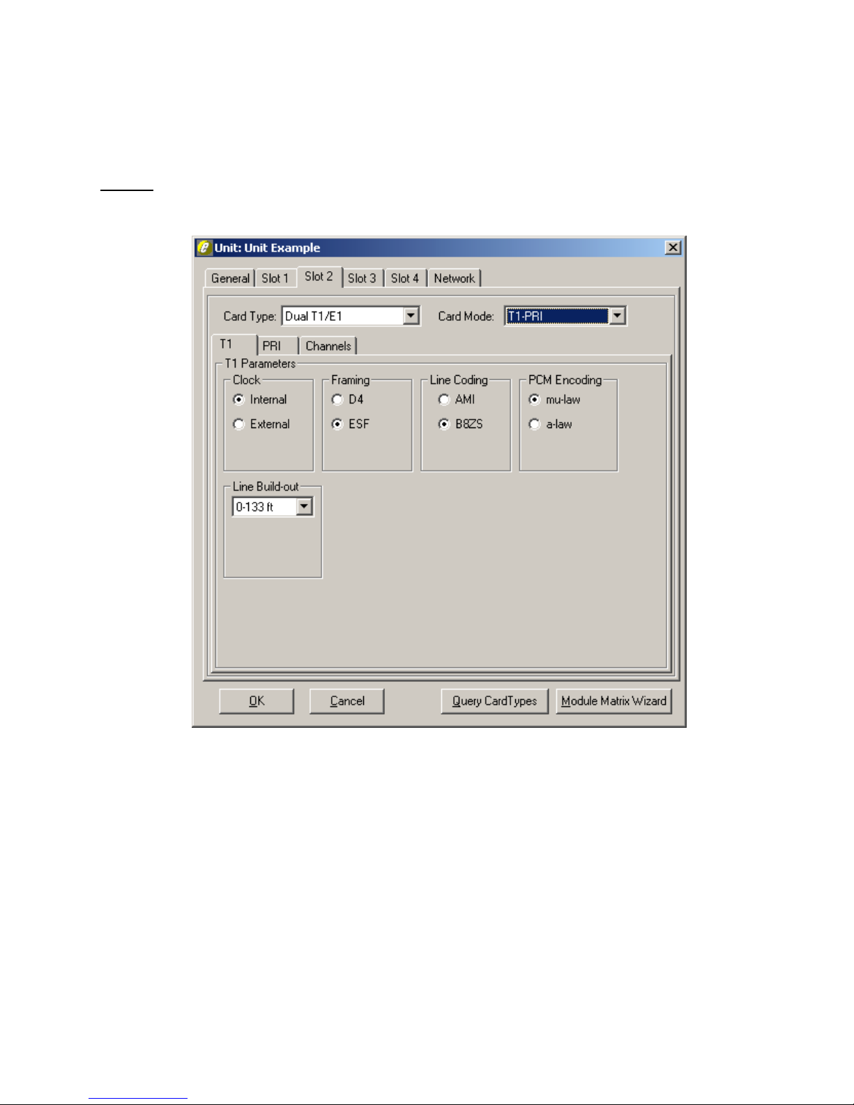
TSP Edge User’s Manual
T1 PRI (North American Standards)
The Edge supports a bearer capability of “Speech” or “3.1 kHz Audio”.
T1 Tab
Figure 40 shows the parameters on the T1 tab in the T1-PRI card mode.
Clock
The Clock needs to be set to where one end is providing timing (normally the PSTN)
while the other end is deriving clock from it (usually the CPE). The Internal clock
setting is used when the Edge acts as the PSTN and provides the clocking to the
equipment under test. External Clock is used when the Edge acts as the CPE and
clocks from the equipment under test (i.e., if the Edge is set for Internal clock, the
equipment under test should be set for External clock, and vice versa).
40-400-00065, Rev. E
88
Figure 40. T1-PRI Card Mode T1 Tab
Page 99

Framing
For Framing, both ends need to match otherwise synchronization will not be
achieved. D4 is considered a legacy format while ESF (extended superframe) has
more features available such as CRC-4 for detection of errors without interrupting the
signal.
Line Coding
For Line Coding, AMI suffices if no DDS data exists on any of the T1 channels.
B8ZS is used when DDS data channels are present to compensate for when an all
Zeros state exist (when equipment is off) which can lead to lost of synchronization on
the T1 due to too many successive zeros.
PCM Encoding
The Edge configuration software defaults to mu-law PCM Encoding which is the
North American standard for T1. PCM encoding refers to the process used to digitize
the analog signal. It is necessary to ensure this matches the equipment under test. E1
normally uses a-law PCM encoding.
TSP Edge User’s Manual
Note: If using only one port on a Dual T1/E1 that is configured for External
Clock, port 2 must be used and will derive its clock from the equipment under
test. If using both ports, the device connected to Port 1 must use the same
clocking reference as the device connected to port 2.
Line Build-out
The Line Build-out defaults to 0-133 ft (0 dB level) but can be changed for different
distances or dB loss expected on the line.
Important: On Dual T1/E1, both channels are configured for the same
clock, framing (for T1), signaling (for E1), and line coding. Ensure the
T1/E1 parameters are consistent with the configuration of the equipment
under test. This information can be found in the equipment manual or by
contacting the vendor.
40-400-00065, Rev. E
89
Page 100
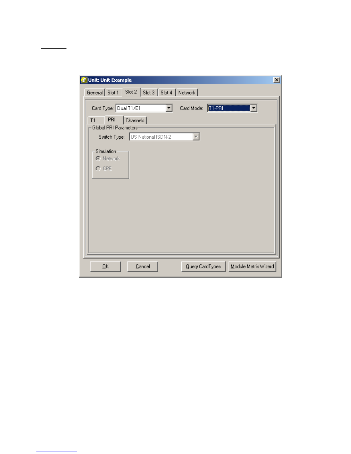
TSP Edge User’s Manual
PRI Tab
The global PRI parameters are configured on this tab (see Figure 41). This includes
programming the PRI switch platform and the end the Edge will simulate.
Figure 41. T1-PRI Card Mode PRI Tab
Switch Type
The options available are AT&T 4ESS, AT&T 5ESS, NT DMS-100/250, and US
National ISDN. These options cover the majority of the North American switch
types.
Simulation
This selection establishes the end the Edge simulates. Select Network if the Edge
simulates the central office. Select CPE if the Edge simulates the Customer Premise
Equipment.
40-400-00065, Rev. E
90
 Loading...