

Teltone TSP Edge, TSP-EDGE-01, TSP-DT1E1-01, TSP-8PFXO-01, TSP-8POTS-01 User Manual
...
TSP Edge
User’s Manual
40-400-00065, Rev. E

Note
This manual covers Model TSP-EDGE-01, hardware modules TSP-DT1E1-01, TSP-8PFXO-01, TSP8POTS-01 and software modules TSP-PRI, TSP-2PRI, TSP-ATS.
Copyright Notice
Copyright © 2002-2004 Teltone Corporation
All Rights Reserved
Trademarks
Teltone is a registered trademark of Teltone Corporation.
TSP is a trademark of Teltone Corporation.
Windows is a registered trademark of Microsoft Corporation.
Other company and product names may be trademarks or
registered trademarks of their respective owners.
Teltone Corporation
Bothell, Washington, USA
Customer Service: 425-951-3388
Technical Support: 425-951-3390
Fax: 425-487-2288
Email: info@teltone.com
Website: www.teltone.com
40-400-00065, Rev. E
ii

Table of Contents
Overview..............................................................................................................1
Standard Features.....................................................................................1
Typical Applications................................................................................2
End-to-End Calls ..............................................................................2
Call Originate and Call Terminate....................................................4
Bulk Call Generation ........................................................................5
Installation Tests...............................................................................5
Telephony Interfaces................................................................................5
Digital Interface Modules .................................................................6
Analog Interface Modules ................................................................7
Advanced Software Modules...................................................................8
TSP-PRI............................................................................................8
TSP-2PRI..........................................................................................9
TSP-ATS...........................................................................................9
License Codes ..........................................................................................9
Setup ....................................................................................................................9
System Requirements...............................................................................9
Power ................................................................................................9
PC .....................................................................................................10
Checking Your Edge Package .................................................................10
Optional Hardware............................................................................10
Optional Software Modules..............................................................11
Installing Hardware Modules...................................................................11
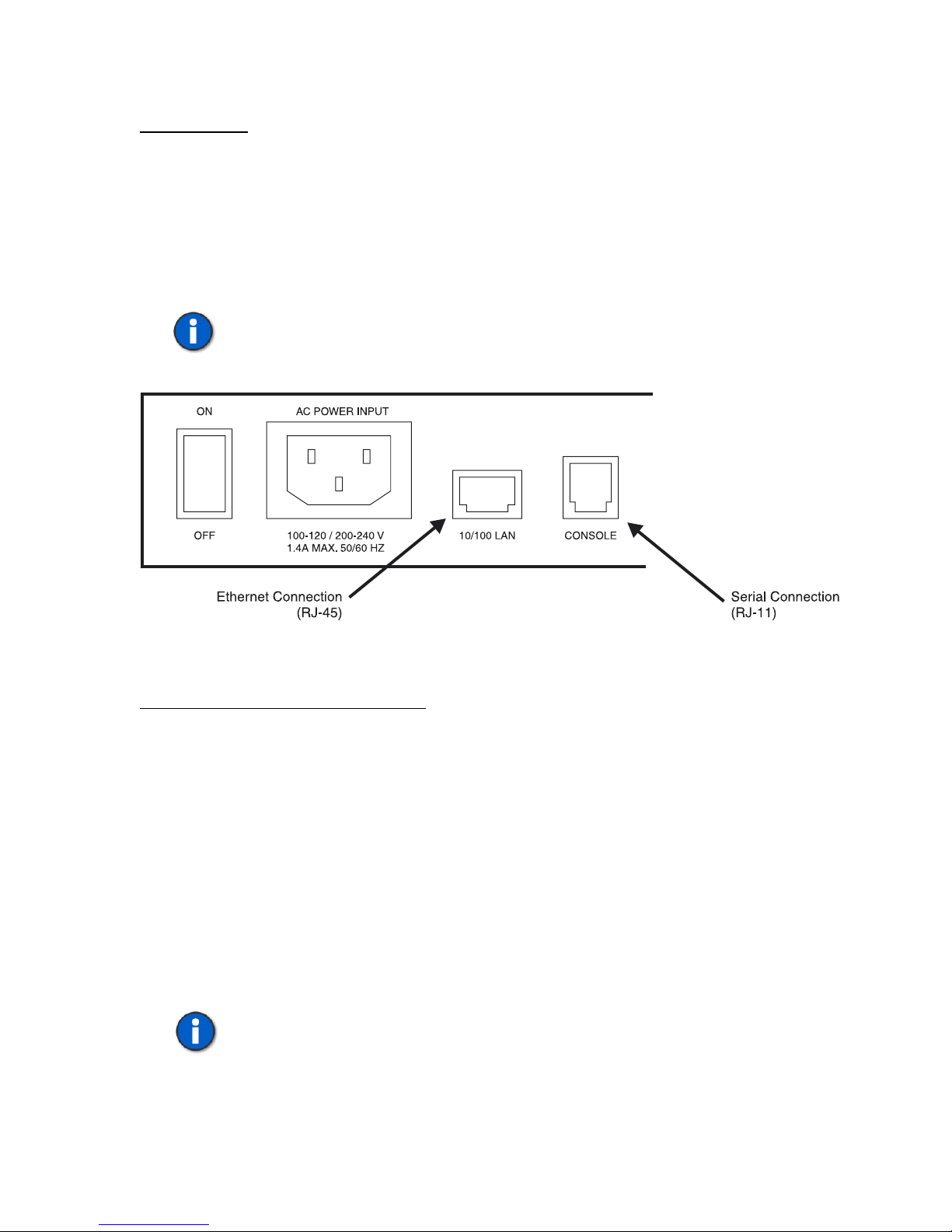
Communications Connections .................................................................12
Console Port......................................................................................13
10/100 LAN (Ethernet) Connection .................................................13
Powering Up the Edge .............................................................................13
Installing Edge Software..........................................................................14
Programming the Edge ........................................................................................14
Basics .......................................................................................................14
Main Window ..........................................................................................15
Menus ...............................................................................................15
Tree Display......................................................................................16
Information Section ..........................................................................16
Icons..................................................................................................16
Control Set Enables ..........................................................................17
Units.........................................................................................................18
Unit Configuration............................................................................18
Viewing Unit Information ................................................................22
Unit Configuration Summary ...........................................................23
Module Configuration ......................................................................23
Module Configuration Summary......................................................33
Templates.................................................................................................33
Type Tab...........................................................................................34
40-400-00065, Rev. E iii

Timings Tab......................................................................................36
Signaling Tab....................................................................................38
Template Configuration Summary ...................................................39
Control Sets..............................................................................................40
Control Set Type Field......................................................................40
Template Field..................................................................................42
Channel Assignments .......................................................................43
Start and Stop....................................................................................44
End-to-End Example ........................................................................45
Control Set Configuration Summary................................................47
Options.....................................................................................................48
Alerts Tab .........................................................................................48
Upgrades Tab....................................................................................48
Unassigned Channels Tab.................................................................50
Executing and Viewing Simulations....................................................................51
Executing a Simulation............................................................................51
Event Log.................................................................................................52
Diagnostics...............................................................................................55
Trace ........................................................................................................56
Test Automation Interface ...................................................................................58
Basic Operation........................................................................................58
Communicating with Edge Configuration Software Using DDE.....59
Communicating with Edge Configuration Software Using TCP .....60
Commands ...............................................................................................61
GETMESSAGES..............................................................................61
GETSTATUS ...................................................................................62
INITIALIZE .....................................................................................63
LISTCARDS.....................................................................................64
LISTCHANNELS.............................................................................65
LISTFILES .......................................................................................66
LISTTASKS .....................................................................................67
LISTUNITS ......................................................................................68
LOADFILE.......................................................................................69
RUNTASK .......................................................................................70
SETDIAGNOSTIC...........................................................................71
SETMONITOR.................................................................................72
SETPRIEVENTS..............................................................................73
Warning Messages...................................................................................74
Events.......................................................................................................76
Event Number Reference Tables .............................................................77
Standard Messages............................................................................77
PRI Send Messages...........................................................................79
PRI RCV Messages ..........................................................................80
N_STAT_IN Causes.........................................................................81
CAUSE_IND ....................................................................................83
SIGNAL_IND...................................................................................84
40-400-00065, Rev. E
iv

PROGRESS_IND .............................................................................85
NOTIFY_IND...................................................................................85
INFO_RQ_IND ................................................................................86
FEATURE_IND ...............................................................................86
Primary Rate ISDN Software Modules (TSP-PRI and TSP-2PRI) .....................87
T1 PRI (North American Standards) .......................................................88
T1 Tab...............................................................................................88
PRI Tab.............................................................................................90
Channels Tab ....................................................................................91
E1 PRI (EURO-ISDN).............................................................................92
E1 Tab...............................................................................................93
PRI Tab.............................................................................................95
Channels Tab ....................................................................................96
Advanced Test Scripting Software Module (TSP-ATS) .....................................97
Using ScriptBuilder .................................................................................98
Move, Cut, Copy, Paste, Delete and Undo .......................................100
Navigation Window..........................................................................100
Commands ...............................................................................................100
Conditionals/Timers/Events .............................................................101
Line States ........................................................................................103
Tones/Audio .....................................................................................105
Establishing Audio Connections between Channels................................109
Assigning a Script to a Control Set..........................................................110
Sample Scripts .........................................................................................111
Troubleshooting ...................................................................................................112
Warranty and Service...........................................................................................117
Warranty Information ..............................................................................117
Return Procedures....................................................................................117
Technical Assistance................................................................................117
Maintenance.............................................................................................117
Cleaning............................................................................................117
Servicing ...........................................................................................117
Ordering Information...........................................................................................118
Hardware Chassis.....................................................................................118
Optional Hardware Modules....................................................................118
Optional Software Modules .....................................................................118
Accessories ..............................................................................................118
Extended Warranties................................................................................118
Revision History ..................................................................................................119
Specifications.......................................................................................................122
Appendices...........................................................................................................125
Call Timings and Process Flowcharts......................................................125
Call Timings .....................................................................................125
Call Process Flowcharts....................................................................128
Connector and Cable Pin-outs .................................................................152
Console Port......................................................................................152
40-400-00065, Rev. E v

10/100 LAN (Network) PORT .........................................................153
T1/E1 Ports .......................................................................................153
POTS Ports .......................................................................................154
References............................................................................................................156
Glossary ...............................................................................................................158
Index ....................................................................................................................165
40-400-00065, Rev. E
vi

List of Figures
Figure 1. Edge - Front..........................................................................................1
Figure 2. Single T1/E1 End-to-End .....................................................................3
Figure 3. Dual T1/E1 End-to-End........................................................................3
Figure 4. Analog LS to T1/E1 End-to-End..........................................................4
Figure 5. Analog LS to Analog LS End-to-End ..................................................4
Figure 6. Analog Loop Start, Call Originate and Call Terminate........................5
Figure 7. Edge - Back ..........................................................................................5
Figure 8. Dual T1/E1 Module..............................................................................6
Figure 9. 8 Channel POTS FXS Module .............................................................7
Figure 10. 8 Channel POTS FXO Module...........................................................7
Figure 11. Serial and Ethernet Connections on the Edge Back Panel .................13
Figure 12. Configuration Software New Project .................................................15
Figure 13. Main Window.....................................................................................16
Figure 14. Unit Screen .........................................................................................18
Figure 15. Module Matrix Wizard.......................................................................20
Figure 16. T1 Card Mode T1 Tab........................................................................24
Figure 17. E1 Card Mode E1 Tab........................................................................26
Figure 18. POTS FXS Card Type........................................................................28
Figure 19. POTS FXO Card Type .......................................................................29
Figure 20. Channel Identification ........................................................................30
Figure 21. Channel Configuration Wizard...........................................................32
Figure 22. Template Type Tab.............................................................................34
Figure 23.Template Timings Tab ........................................................................37
Figure 24.Template Signaling Tab ......................................................................38
Figure 25. Control Set..........................................................................................40
Figure 26. Channel Assignments (Analog)..........................................................43
Figure 27. Channel Assignments (T1 Channels) .................................................44
Figure 28. End-to-End Control Set Example.......................................................46
Figure 29. Connecting Channels..........................................................................46
Figure 30. Alerts Tab ...........................................................................................48
Figure 31. Upgrades Tab......................................................................................49
Figure 32. Setting the Default Idle State for Unassigned Channels ....................50
Figure 33. Control Set Information......................................................................51
Figure 34. Call Status...........................................................................................52
Figure 35. Events View on Event Log.................................................................53
Figure 36. Calls View on Event Log ...................................................................54
Figure 37. Select Diagnostic Channels Screen ....................................................55
Figure 38. Diagnostics Window ..........................................................................55
Figure 39. Trace Screen .......................................................................................56
Figure 40. T1-PRI Card Mode T1 Tab ................................................................88
Figure 41. T1-PRI Card Mode PRI Tab...............................................................90
Figure 42. T1-PRI Card Mode Channels Tab......................................................91
Figure 43. E1-PRI Card Mode E1 Tab ................................................................93
Figure 44. E1-PRI Card Mode PRI Tab...............................................................95
40-400-00065, Rev. E vii

Figure 45. E1-PRI Card Mode Channels Tab......................................................96
Figure 46. Script Example Steps..........................................................................97
Figure 47. ScriptBuilder.......................................................................................99
Figure 48. Detecting DTMF Sequence ................................................................106
Figure 49. Control Set Dialog Box with a Script Assigned.................................110
Figure 50. Console Port Pin-out ..........................................................................152
Figure 51. Serial Cable RJ11 to RJ11..................................................................152
Figure 52. Serial Cable Adapters.........................................................................152
Figure 53. Network Port Pin-out..........................................................................153
Figure 54. Ethernet Cross-Over Cable.................................................................153
Figure 55. T1/E1 Module Pin-out........................................................................153
Figure 56. T1/E1 Cable........................................................................................154
Figure 57. 8 Channel POTS FXO Module Pin-out..............................................154
Figure 58. POTS FXS Module Pin-out................................................................154
Figure 59. POTS Y-Cable....................................................................................155
40-400-00065, Rev. E
viii

IMPORTANT USER SAFETY INSTRUCTIONS
When using this product, basic safety precautions, including the following, should always be followed to reduce the risk of fire,
electric shock, and injury to persons.
1. Read and understand all instructions.
2. Follow all warnings and instructions marked on the product.
3. The product should be operated only from the type of power source indicated on the marking label. If you are not sure of the
type of power supply, consult your dealer or local power company. The product is designed for indoor use only.
4. To reduce the risk of electric shock, do not disassemble the product, but take it to qualified service personnel when service or
repair work is required. Opening or removing covers may expose you to dangerous voltages or other risks. Incorrect reassembly
can cause electric shock when the appliance is subsequently used.
5. If the product does not operate normally by following the operating instructions, or if the product has been dropped or the
cabinet has been damaged, or if the product exhibits a distinct change in performance, refer servicing to qualified service
personnel.
6. If the product is used in a manner other than specified in this manual, the protection provided by the product may be impaired.
7. For the purpose of removing power from the product, the power input connector is the main power disconnect point. Pull the
power cord away from the connector to ensure power disconnect.
8. Adequate air flow must be maintained in order for the product to operate correctly. Do not wrap the product in blankets, paper,
or other material that may impede ventilation.
40-400-00065, Rev. E ix

x
U.S. REGULATORY COMPLIANCE
FCC Part 15 Class A Notice: This equipment has been tested and found to comply with the limits for a Class A digital device,
pursuant to part 15 of the FCC Rules. These limits are designed to provide reasonable protection against harmful interference when
the equipment is operated in a commercial environment. This equipment generates, uses, and can radiate radio frequency energy
and, if not installed and used in accordance with the instruction manual, may cause harmful interference to radio communications.
Operation of this equipment in a residential area is likely to cause harmful interference in which case the user will be required to
correct the interference at his own expense.
The Installation Category (OVERVOLTAGE CATEGORY) for this device is II and it is designed to be safe under POLLUTION
DEGREE 2, per IEC 1010-1: 1990 specifications.
The following only applies to the TSP-8PFXO-01 module:
FCC Part 68 Notice: To comply with FCC Part 68 regulations, the following requirements must be met:
1. If the telephone company requests information on the equipment connected to their lines, please tell them:
a. the telephone number the equipment is connected to;
b. this equipment operates on standard RJ11 phone jacks;
c. the FCC registration number;
d. the ringer equivalence number (REN). The REN shows how many devices, such as phones, modems, etc. can be
connected to your line. In most areas, there cannot be more than five devices (i.e., a REN of five) on a phone line. If the
REN is exceeded, then your phone may not ring properly.
NOTE: Items C and D above are found on the label on any Teltone equipment connected to your telephone line.
2. These devices must not be installed on coin-operated telephone lines or party lines.
3. Repair work on this device must be done by Teltone Corporation.
4. If any trouble is experienced with this equipment, the telephone company may request that the customer disconnect the
registered equipment from the telephone line to determine if the registered equipment is malfunctioning and if the registered
equipment is malfunctioning, the use of such equipment shall be discontinued until the problem has been corrected.
The following only applies to the TSP-8PFXO-01 module:
CANADIAN REGULATORY COMPLIANCE
Notice: This equipment meets the applicable Industry Canada Terminal Equipment Technical Specifications. This is confirmed by
the registration number. The Industry Canada label or the abbreviation, IC, before the registration number signifies that registration
was performed based on a Declaration of Conformity indicating that Industry Canada technical specifications were met. It does not
imply that Industry Canada approved the equipment. Industry Canada does not guarantee the equipment will operate to the user's
satisfaction. Before installing this equipment, users should ensure that it is permissible to connect it to the facilities of the local
telecommunications company. The equipment must also be installed using an acceptable method of connection. In some cases, the
company’s inside wiring associated with a single line individual service may be extended by means of a certified connector
assembly (telephone extension cord). The customer should be aware that compliance with the above conditions may not prevent
degradation of service in some situations.
Repairs to certified equipment should be made by Teltone Corporation. Any repairs or alterations made by the user to this
equipment, or equipment malfunctions, may give the telecommunications company cause to request the user to disconnect the
equipment. Users should ensure for their own protection that the electrical ground connections of the power utility, telephone lines,
and internal metallic water pipe system, if present, are connected together. This precaution may be particularly important in rural
areas.
Caution: Users should not attempt to make such connections themselves, but should contact the appropriate electric inspection
authority, or electrician, as appropriate. The Ringer Equivalence Number (REN) assigned to each terminal device provides an
indication of the maximum number of terminal devices to be connected to a telephone interface without overloading the interface.
The termination on an interface may consist of any combination of devices subject only to the requirement that the sum of the REN
of all devices does not exceed five (5) in most, but not all cases. Check with your local exchange carrier for the REN limit in your
service area. The REN assigned to each device is located on the equipment label.
COMPLIANCE NOTICE: This digital apparatus does not exceed the Class A limits for Radio Noise Emissions set out in the
equipment standard ICES-003 for digital apparatus.
AVIS DE CONFORMATION: Le présent appareil numérique n’émet pas de bruits radioélectriques dépassant les limites applicables
aux appareils numériques de la class A prescrites dans le Règlement sur le brouillage radioélectriques édicté par le ministère des
Communications du Canada.
40-400-00065, Rev. E
OVERVIEW
The Teltone TSP Edge is a combined hardware and software platform used to
simulate connections to different telephony interfaces. These include T1, E1, analog
POTS FXS, and analog POTS FXO. An RS-232 port and an Ethernet port are
provided to configure and control the Edge.
Telecom Simulation Platform
TSP Edge
Standard Features
• Base unit for configuring with optional hardware plug-in modules
• Upgradeable software and hardware modular design
• Analog POTS and T1/E1 simulation in the same system
• Operates under Windows 95/98/2000/XP or Windows NT
• Programming and control can be done with either the serial or Ethernet
connection
• Status display provides current state for each channel (on/off-hook, ringing,
etc)
• Supports three call types
o Originate – calls placed by the Edge to a connected device
o Terminate – calls placed into the Edge by a connected device
o End-to-End – calls placed through the Edge by one device to another
• Call progress and DTMF signaling
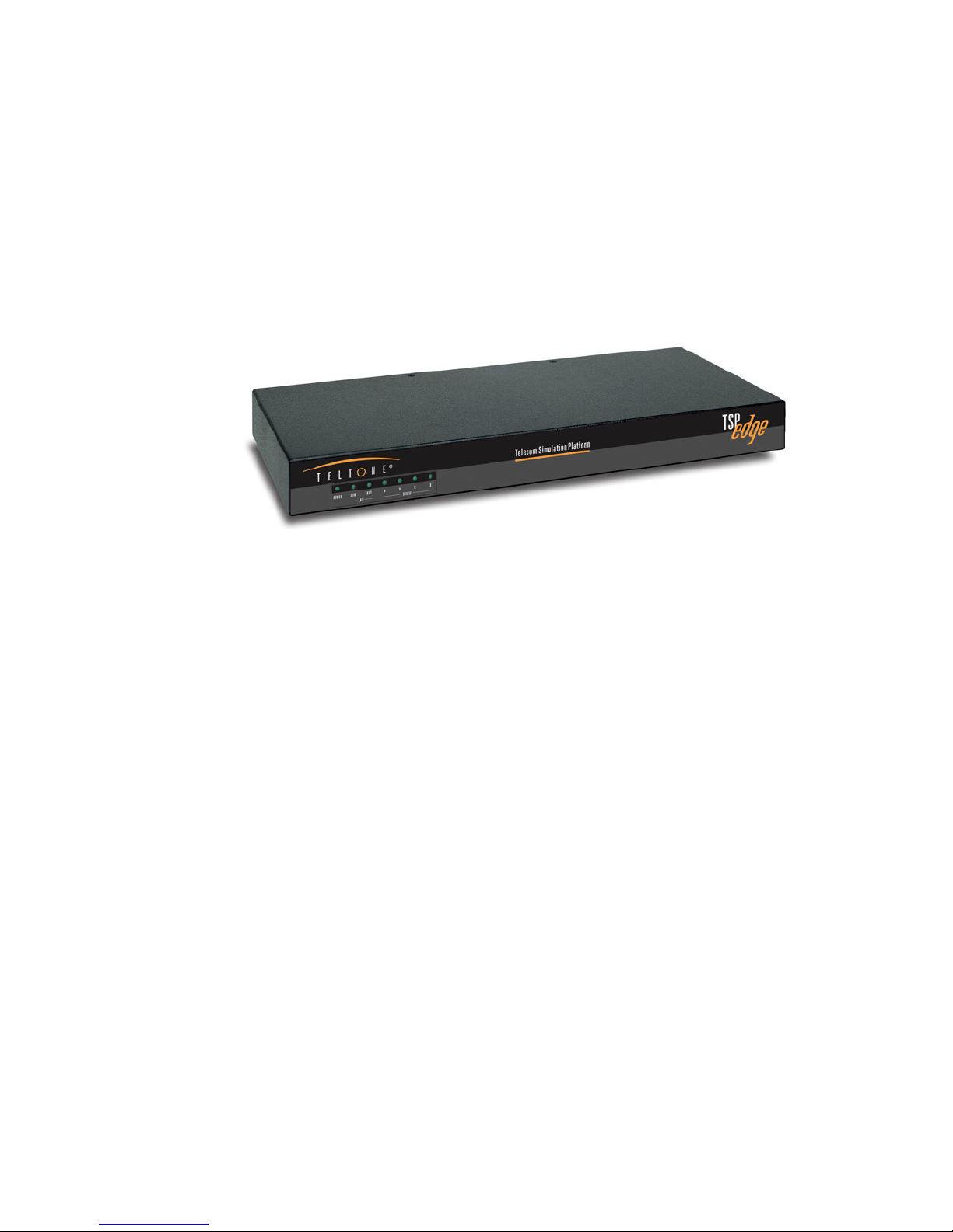
Figure 1. Edge - Front
• Event logging of
o On/off-hook
o Ringing
40-400-00065, Rev. E 1

TSP Edge User’s Manual
o Time to answer
o Call duration
o Errors such as T1/E1 loss of sync
o Date/time of each event
• Programmable call parameters
o Analog channel types: Loop Start FXS and FXO
o T1 channel type (robbed bit signaling): Loop Start, Ground Start,
Immediate Dial, Wink Start, Delay Dial
o E1 channel signaling including: CAS Q.421 with DTMF Variation,
Loop Start, Ground Start, Wink, Immediate Dial, Delay Dial
o CAMA or Tie Trunk operation
o Programmable T1 and E1 signaling bit states for A, B, C & D bits
o T1/E1 Clear channel “nailed up” 64 KB/s connection
o Call Timing: Call Duration, Guard Time, Far-end Disconnect Time,
Delay Before Audio Message
o Dial String: ANI/DNIS Transmit Digits –40 Digits,
Phone Number –40 Digits
o Dial Tone: Enable, Delay Before, Length
o Ringback: Enable, Duration
• Bulk call generation
• Diagnostics with ability to place channels in different signaling states and
shows the signaling bit states on T1/E1
• Trace for detailed call progress of a channel
• Ability to control multiple Edge units with a single computer via the Ethernet
connection
Typical Applications
The Edge is configurable for three basic types of calls: End-to-End, Call Originate,
and Call Terminate. End-to-End calls are similar to calls placed through any switch;
calls are originated on one end and are terminated on the other end. However, in some
applications, you may want to simulate incoming traffic to a connected device; these
calls are originated from within the Edge. You may also want to monitor outgoing
traffic from a connected device, these calls are Terminated into the Edge.
End-to-End Calls
End-to-End calls are ones where one channel is connected to another. They are
initiated by an external device connected to the Edge, attempting to make a
40-400-00065, Rev. E
2

TSP Edge User’s Manual
connection to another external device. For example, calling from one modem to
another on a pair of POTS connections, or from a POTS connection to a T1 modem
bank for V.90 modem testing. A T1/E1 Clear Channel application is where a single
channel operates as a 64 KB/s pipe, with no framing or control bits in the data stream.
The channel is cross-connected to another T1/E1 Clear Channel via the Control Set.
Dialed, Channel Bank, DS0 to DS0 (for Clear Channel operation only) and Switch
Emulation are the types of End-to-End Control Sets used by the Edge.
The Edge cross connects a channel on the T1/E1 to another channel on the same
T1/E1 (see Figure 2).
TSP Edge
Equipment under
Test
T1/E1
Single or
Dual T1/E1
Module
Figure 2. Single T1/E1 End-to-End
The Edge cross connects a channel on the first T1/E1 to any channel on the second
T1/E1 (see Figure 3).
Equipment under
Test
Equipment under
Test
T1/E1
T1/E1
TSP Edge
Single or
Dual T1/E1
Module
Figure 3. Dual T1/E1 End-to-End
40-400-00065, Rev. E
3

TSP Edge User’s Manual
The Edge connects an Analog Loop Start channel to a T1/E1 channel (see Figure 4).
TSP Edge
123
456
789
8#
*
Term Set
2-wire Loop
4 or 8
Channel
POTS
Module
Equipment under
Test
T1/E1
Single or
Dual T1/E1
Module
Figure 4. Analog LS to T1/E1 End-to-End
The Edge connects an Analog Loop Start channel to another Analog Loop Start
channel (see Figure 5).
TSP Edge
123
456
789
8#
*
Term Set
123
456
789
8#
*
2-wire Loop
4 or 8
Channel
POTS
Module
2-wire Loop
Term Set
Figure 5. Analog LS to Analog LS End-to-End
Call Originate and Call Terminate
The Edge generates calls to the equipment under test in Call Originate mode. Call
Terminate mode is where the Edge receives calls from the equipment under test. In
both cases, the Edge will count the calls, and display the calls as completed,
unanswered, or busy in the event log. Once the calls are established; a WAV file can
be programmed to play to indicate that a call has taken place.
With Call Originate mode, the Edge generates calls on the channels of a T1/E1 line to
the equipment under test. With a Dual T1/E1 module, the calls can be generated on
both T1/E1s simultaneously. Call Terminate mode is where the Edge receives calls
from the equipment under test on the channels of the T1/E1 lines (see Figure 3).
For the POTS channels, the Edge generates calls to term set in Call Originate mode.
Call Terminate mode is where the Edge receives calls from the term set (see Figure
6).
40-400-00065, Rev. E
4
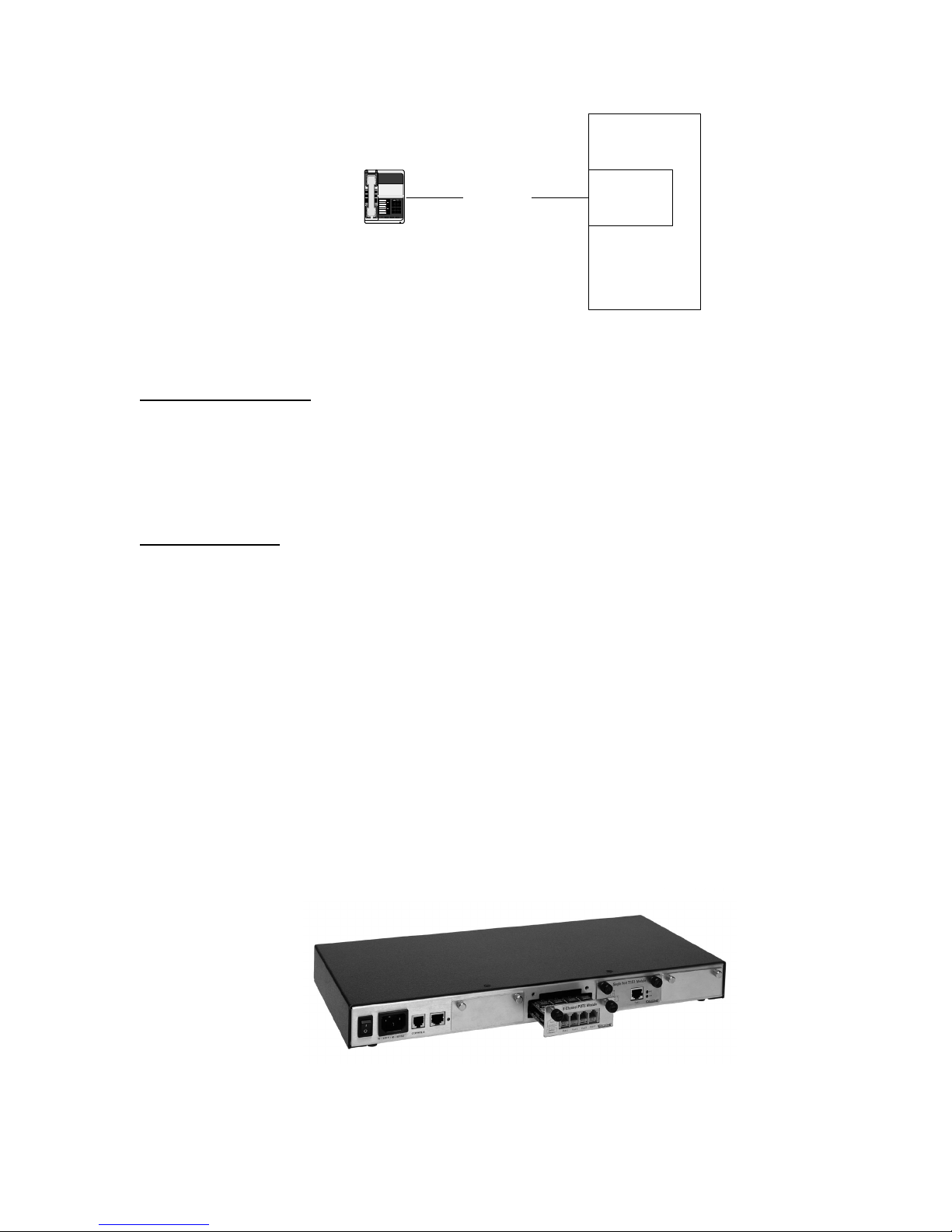
Figure 6. Analog Loop Start, Call Originate and Call Terminate
Bulk Call Generation
Call Originate mode can be used for Bulk Call Generation. Bulk Call Generation are
calls that originate within the Edge, simulating call traffic, terminating at an external
device, often with some audio file playback when the external device answers. This
can be used to “stress test” the equipment under test.
123
456
789
8#
*
Term Set
2-wire Loop
TSP Edge User’s Manual
TSP Edge
4 or 8
Channel
POTS
Module
Installation Tests
The Edge can emulate the PSTN and be terminated to a PBX via a T1/E1 circuit or
multiple POTS connections. This allows for testing PBX programming and
functionality before live traffic is cut over to it.
Telephony Interfaces
The Edge has a modular design (see Figure 7) and the following hardware options:
• Dual T1/E1 module
• 8 Channel POTS FXS module
• 8 Channel POTS FXO module
• Single T1/E1 module (discontinued)
• 4 Channel POTS module (discontinued)
40-400-00065, Rev. E
Figure 7. Edge - Back
5
TSP Edge User’s Manual
Digital Interface Modules
Dual T1/E1 Module
The Dual T1/E1 interface module (see Figure 8) supports T1, E1, and PRI
configurations.
LINK This LED indicator shows that the T1/E1 link is active
ERR This LED indicator shows that an error has occurred
Figure 8. Dual T1/E1 Module
Single T1/E1 Module (Discontinued)
The Single T1/E1 module is identical to the Dual T1/E1 except there is only one port.
40-400-00065, Rev. E
6
TSP Edge User’s Manual
Analog Interface Modules
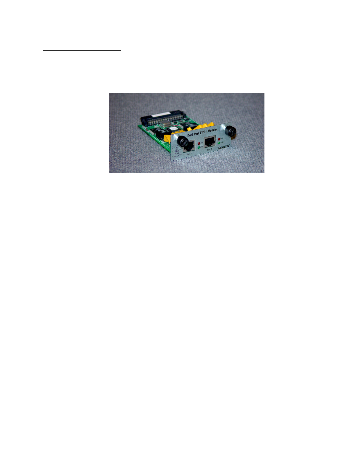
8 Channel POTS FXS Module
The 8 Channel POTS FXS interface module (see Figure 9) provides eight (8)
channels which appear as Central Office or PBX lines. The interface provides battery,
ringing and call progress to the equipment under test, and can detect on and off-hook
conditions and DTMF signaling from the connected equipment.
The interface uses industry standard RJ11 jacks wired to RJ14 standards.
Figure 9. 8 Channel POTS FXS Module
8 Channel POTS FXO Module
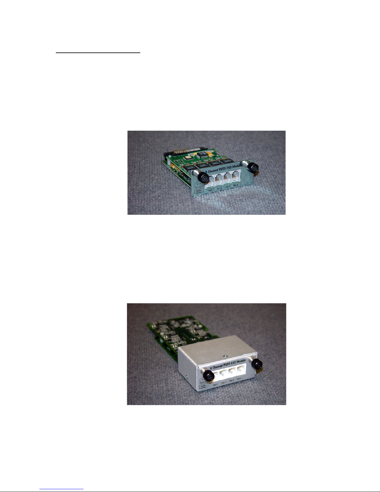
The 8 Channel POTS FXO interface module (see Figure 10) provides eight (8)
channels which appear as telephones to the equipment under test. The interfaces can
detect ringing, go on and off-hook and transmit DTMF dialing.
The interface uses industry standard RJ11 jacks wired to RJ14 standards.
Figure 10. 8 Channel POTS FXO Module
40-400-00065, Rev. E
7

TSP Edge User’s Manual
4 Channel POTS Module (Discontinued)
The 4 Channel POTS interface module provides four (4) channels which appear as
Central Office or PBX lines. The interface provides battery, ringing and call progress
to the equipment under test, and can detect on and off-hook conditions and DTMF
signaling from the connected equipment.
The interface uses industry standard RJ11 jacks.
The 4 channel POTS module is identical to the 8 channel FXS module, except there is
only 1 channel available per port.
Advanced Software Modules
TSP-PRI
TSP-PRI (Primary Rate ISDN): This software module includes the standard Edge
features plus it adds either T1 or E1 Primary Rate ISDN to an Edge unit that has no
PRI capability licensed.
T1 Primary Rate ISDN:
• Includes multiple switch types:
o US National ISDN-2
o AT&T 4ESS
o AT&T 5ESS
o NT DMS-100/250
• Simulates CPE end or Network end
• Provides the following capabilities:
o Direct dialing in (DID)
o Subaddressing
o Delivery of Called and Caller number (CLIP)
o Delivery of Type of Address and Numbering Plan
E1 Primary Rate ISDN:
• Includes EURO-ISDN switch type
• Simulates CPE end or Network end
• Provides the following capabilities:
o Direct dialing in (DID)
o Subaddressing
40-400-00065, Rev. E
8

TSP Edge User’s Manual
o Delivery of Called and Caller number (CLIP)
o Delivery of Type of Address and Numbering Plan
TSP-2PRI
The TSP-2PRI software module adds either T1 or E1 Primary Rate ISDN to an Edge
unit that already has one of the two types installed.
TSP-ATS
TSP-ATS (Advanced Test Scripting): This software module includes the standard
Edge features plus user defined scripts including:
• User-definable call sequences
• Send DTMF during a call
• Detect DTMF during a call
• Send test tones
• Detect broadband energy
• Detect voice
• Play multiple wave files on a channel
License Codes
Edge license codes are used for:
• Enabling additional purchased software modules
• Setting warranty information
For information about upgrading the Edge, see “Upgrades Tab” on page 48.
SETUP
System Requirements
Power
Caution: AC operating power must be within 90 to 250 volts AC and the
operating frequency from 43 to 63 Hz.
The Edge unit uses an industry standard IEC three prong connector so that almost any
international power cord can be used. A standard North American power cord is
provided with the unit.
40-400-00065, Rev. E
9

TSP Edge User’s Manual
PC
• PC with Windows 95/98/XP/2000 or Windows NT
• Serial port interface on PC (standard RS-232 DCE interface – cable provided
with Edge)
• Ethernet connection to PC (crossover cable with RJ45 connectors provided) or
to LAN (standard Ethernet cable not provided)
• Monitor, keyboard, and mouse or equivalent devices
• 2X Speed CD-ROM drive
The following minimum disk storage capacities are required for the basic installation
and storage of saved files:
6 Mb required on the disk with the Windows operating system
4 Mb required on the disk the application is installed on
7 Mb additional required to install the Adobe Acrobat reader
Checking Your Edge Package
When you receive your Edge unit, you should receive the following components:
• TSP-EDGE-01 unit
• 120 VAC power cord
• RJ45 Ethernet cross over cable (gray cable, labeled)
• RJ11 serial cable
• RJ11 to DB9 adapter
• RJ11 to DB25 adapter
• Two RJ45 - T1/E1 cables (yellow cable, labeled)
• Rack-mount Bracket Kit (2 brackets and 8 mounting screws)
• Edge Configuration Software (CD-ROM)
• Product Registration Card
Optional Hardware
• Dual T1/E1 interface module
• 8 Channel POTS FXS interface module
• 8 Channel POTS FXO interface module
• Y-Cable Kit (set of 4, to use with 8 Channel POTS interface modules)
40-400-00065, Rev. E
10

TSP Edge User’s Manual
Optional Software Modules
• TSP-PRI: Adds T1 or E1 Primary Rate ISDN (you select T1 or E1 upon
installation) NOTE: For older TSP-BASE units, only T1 PRI is available.
• TSP-2PRI: Extends TSP-PRI module to include both T1 and E1 Primary Rate
ISDN. NOTE: For TSP Edge units only.
• TSP-ATS, Advanced Test Scripting software module. NOTE: For TSP Edge units
only.
If any of the items you ordered are missing or damaged, please contact Teltone
customer service.
Caution: The Edge modules are (electro-static discharge) sensitive devices and
are shipped in static shield packaging. Proper precautions are needed to avoid
damaging them when handled. Teltone Corporation requires any returned
modules to be properly packaged in static shield packaging.
Installing Hardware Modules
Before applying power to the Edge, ensure that the telephony interface modules are
installed per the following information and Table 1. Ensure the modules are securely
seated and the thumb-screws are tightened.
Note: Slot count is 1-4 from left to right when looking at the back of the Edge.
1. If using a T1/E1 module, install it in slot 4.
a. Two T1/E1 modules may be used ONLY if they are both Single T1/E1
modules and no other modules are installed. Install the Single T1/E1
modules in slots 3 and 4.
2. When installing POTS modules (both FXO and FXS types), install the first
module in slot 3 and work to the left.
a. If installing both FXO and FXS modules, place the FXS modules to the
left of the FXO modules.
b. If installing both 4 and 8 Port POTS FXS modules, place the 4 Port
module to the left of the 8 Port module.
c. When using a 4-Port POTS module, at most only one other module may
be installed.
40-400-00065, Rev. E
11

TSP Edge User’s Manual
Table 1. Module Interface Matrix
Number of Each Module Type Module Placement
Slot 1 Slot 2 Slot 3 Slot 4 8 Channel
Slot count is 1-4 from left to right when looking at the back of the Edge.
POTS FXS
8 Channel
POTS FXO
Dual Port
T1/E1
1 T1/E1
1 POTS-FXO
2 POTS-FXO POTS-FXO
3 POTS-FXO POTS-FXO POTS-FXO
1 1 POTS-FXO T1/E1
2 1* POTS-FXO POTS-FXO T1/E1*
3 1* POTS-FXO POTS-FXO POTS-FXO T1/E1*
1 POTS-FXS
2 POTS-FXS** POTS-FXS**
3 POTS-FXS POTS-FXS POTS-FXS
1 1 POTS-FXS** T1/E1
2 1* POTS-FXS POTS-FXS T1/E1*
3 1* POTS-FXS POTS-FXS POTS-FXS T1/E1*
1 1 POTS-FXS** POTS-FXO
1 2 POTS-FXS POTS-FXO POTS-FXO
2 1 POTS-FXS POTS-FXS POTS-FXO
1 1 1* POTS-FXS POTS-FXO T1/E1*
1 2 1* POTS-FXS POTS-FXO POTS-FXO T1/E1*
2 2 1* POTS-FXS POTS-FXS POTS-FXO T1/E1*
* Only the second port of a Dual-T1/E1 module will be active if more than one POTS module is installed. Port 1 of a Dual-
T1/E1 module will be disabled in these configurations.
** A 4 Port POTS module may be used in place of an 8 Port POTS FXS module in these configurations. The 4 Port POTS
module must be installed to the left of any other module.
If using Single T1/E1 modules:
A Single T1/E1 module may be used in place of the Dual T1/E1 module in any of the above configurations.
Two Single T1/E1 modules may be used if no other modules are installed in the Edge. The modules must be placed in slots
3 and 4.
If using 4 Port POTS modules:
A 4 Port POTS module may be used in place of an 8 Port POTS FXS module in any configuration in which there are at
MOST two modules. The 4 Port POTS module must be installed to the left of any other module.
Two 4 Port POTS modules may be used only if no other modules are installed in the Edge. The modules must be placed in
slots 2 and 3.
Communications Connections
Configuring and control of the Edge can be done with either a serial connection to a
PC or with an Ethernet connection directly to a PC or to a LAN. It is necessary to use
the serial connection to initially program the IP for the Ethernet connection.
For pin-out details, see “Connector and Cable Pin-outs” on page 152.
Important: When using the T1/E1 module in T1-PRI or E1-PRI mode, the
network connection must be used for programming and control; the serial
connection is not allowed. This allows for enhanced messaging during PRI
operation.
40-400-00065, Rev. E
12
TSP Edge User’s Manual
Console Port
The Console Port is an RS-232 serial connection for configuration and control of the
Edge. The connection is an RJ11 jack on the Edge, with cables and adapters provided
for connection to either a DB9 or DB25 connection on the PC.
Connect the serial cable (RJ11 jack at both ends) to the Edge at the jack labeled
Console. Connect the other end to the PC’s serial port using the DB9 or DB25
adapter.
Important: Initial programming of the Edge must be done with this connection.
Figure 11. Serial and Ethernet Connections on the Edge Back Panel
10/100 LAN (Ethernet) Connection
The network connection is a 10/100 Base-T which can be used for configuration and
control of the Edge, and which is necessary for downloading voice messages and
software upgrades to the Edge.
An Ethernet cross-over cable (RJ45 at both ends) is provided for connecting directly
to a PC. If connecting via a network hub, a standard straight-through network cable is
required. See “Network Connection” on page 21 for more details.
Powering Up the Edge
The Edge uses a universal power supply that operates from 90 to 250 VAC, 43 to 63
Hz. Connect the power cord and turn on the unit using the switch on the back of the
unit.
Note: Grounding is assured by using the appropriate (approved) power cord.
40-400-00065, Rev. E
13

TSP Edge User’s Manual
The green POWER LED on the front panel will indicate the status of the system. The
LED should be solid green. If the LED fails to light, check your power connections
and verify the switch is in the ON position. If the LED still fails to light, disconnect
power immediately and contact Teltone Technical Support at 425-951-3390.
Important: Adequate airflow must be maintained in order for the unit to
operate correctly. Do not wrap the unit in blankets, paper or other material that
may impede ventilation.
Installing Edge Software
The Edge configuration software is supplied on a CD-ROM disk and uses the
common Windows setup routine. Ensure you have the latest version by going to the
Teltone website (www.teltone.com) and verifying the version available or call
Teltone technical support.
An autorun facility initiates the installation process automatically when the CD-ROM
is installed into the disk drive. An alternative method is to insert the CD-ROM, then
select START, RUN, BROWSE, then choose your CD-ROM drive, and the file
labeled SETUP.EXE. Follow the on screen instructions.
For information about the current and previous versions of the software, see
“Revision History” on page 119.
PROGRAMMING THE EDGE
The Edge configuration software installed on the PC controls the Edge unit and its
configuration. Multiple projects can be saved and used for different testing
applications and units.
Basics
The Edge configuration software allows a user to define Edge Project configurations
in terms of Units, Templates, and Control Sets.
A Unit defines the configuration of a physical Edge unit, the communications
interface used to control it, the hardware modules installed in it, and configuration
parameters for those hardware modules. Within a unit are:
• Slots - the physical card slots where modules are installed
• Ports - the individual connectors on the modules
• Channels - the individual lines or timeslots on each port. Each channel is
identified throughout the configuration software using a unique ID string,
based upon the channel’s location within a particular unit (see “Channel
Identification” on page 30).
40-400-00065, Rev. E
14
Templates define protocols, timings and signaling to be applied to channels within
one or more units.
Control Sets define the action to be taken (such as call origination), which channels
are to be used, what templates are assigned to those channels, and when the action is
to start and stop.
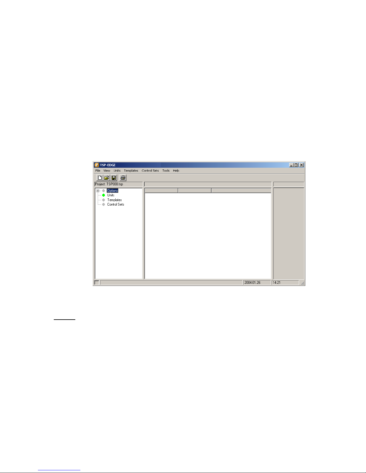
Main Window
Once all connections have been made and the unit is powered up, start the Edge
configuration software.
The main window starts with a default project file and is ready for configuring the
Edge (see Figure 12).
TSP Edge User’s Manual
Figure 12. Configuration Software New Project
Menus
File – for creating, opening and saving project files, and exiting the program.
View – to access and clear the event log and to access Options.
Units – to edit unit-specific parameters for each Edge unit, and to initialize a unit.
Templates – to edit templates.
Control Sets – to edit control sets.
Tools – to access the Diagnostic and Trace functions.
Help – to access the Help file and About dialog box.
40-400-00065, Rev. E
15
TSP Edge User’s Manual
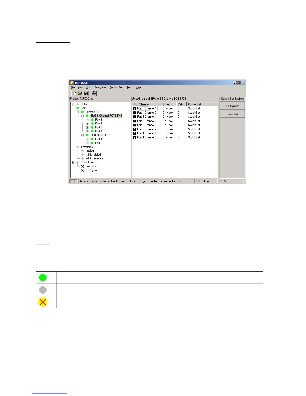
Tree Display
On the left side of the main window is a tree display for Options, Units, Templates,
and Control Sets. A plus sign (+) appears in front of each of these as simulation
parameters are created. Clicking the plus sign (+) expands the display tree and
clicking the minus sign (-) does the opposite. See Figure 13.
Information Section
To the right side of the tree display is the information section. The information
section displays parameters and current states of the item chosen in the tree display.
Icons
The following icons are used in the tree display and information section.
Everything is OK. (Green Dot)
This item has no status. (Gray Dot)
Error lower in tree. (Yellow Dot with Red X)
Figure 13. Main Window
General Status
40-400-00065, Rev. E
16
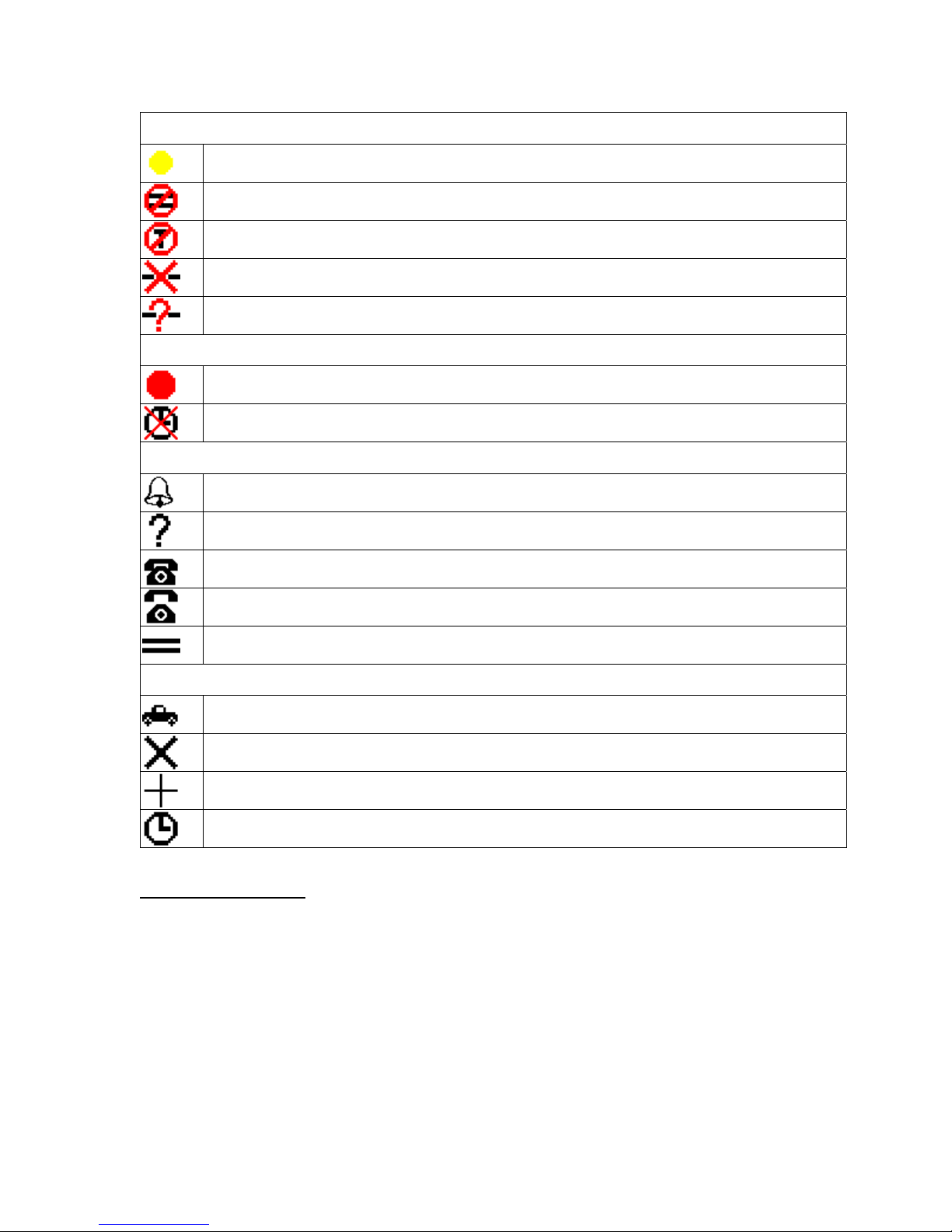
TSP Edge User’s Manual
Unit Status
Attempting to communicate with Edge. (Yellow Dot)
Card Definitions do not match.
Unit connected is not an Edge unit or requires a license code.
Communication error to unit.
No Comm port defined for unit.
T1/E1 Alarms
T1/E1 Alarm (Red Dot) - Check that the T1/E1 cable is connected and that the T1/E1
parameters for the connected device are configured the same as the unit.
T1/E1 Clock Sync Error - Check that the T1/E1 parameters for the connected device are
configured the same as the unit.
Channel Status
Channel is ringing.
No status available.
Channel is On-hook.
Channel is Off-hook.
Clear Channel
Control Set Status
Control set is running.
Control set Disable.
Control Set Finished.
Control Set Waiting for Start Time
Control Set Enables
The Control Set Enable buttons appear on the far right side of the main window once
Control Sets have been created. These buttons are used to activate control sets.
During programming and control of the Edge, the small box at the bottom left corner
of the main window turns yellow indicating commands are being sent to the Edge.
Once complete, the box turns gray.
40-400-00065, Rev. E
17
TSP Edge User’s Manual
Units
Unit Configuration
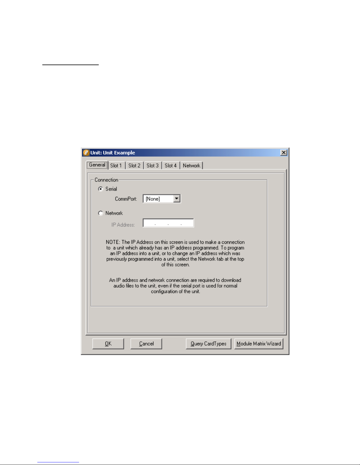
Each Edge must be defined as a “Unit” in the configuration software. The Unit screen
(see Figure 14) is used to define the connection for communicating to the Edge, the
card types installed in the unit, and specific information for the Ports and Channels on
each card.
By clicking New on the Units menu, the prompt “Enter New Unit Name” appears.
For demonstration purposes, the name “Unit Example” is used in this manual. After
entering the name for your unit, the Unit screen is displayed (see Figure 14) with the
unit name in the title bar.
Note the tabs on the Unit screen: General (Connection for Serial or Network
control), Slots 1 - 4 (for card types), and Network (for assigning an IP address to the
unit).
40-400-00065, Rev. E
18
Figure 14. Unit Screen

The Unit screen is displayed with the General tab selected. This tab is used to select
the type of connection that will be used to communicate to the Edge. A Serial
connection must be used initially since no IP address is assigned for a Network
connection at this point.
Serial Connection
The serial connection is mandatory for initial setup of the Edge. It must be used to
establish control of the unit and to set it up for network control. Select the
CommPort that will be used to control the unit.
When using a T1/E1 module in T1-PRI or E1-PRI mode, a network connection
must be used for programming and control; a serial connection is not allowed.
This allows for enhanced messaging during PRI operation.
Query Card Types
At this point, the unit in the Edge configuration software can be configured to match
the modules installed in the physical unit. This can be done automatically by clicking
the Query Card Types button at the bottom of the Unit screen. A message is displayed
stating “This will set the current units card types to match those actually in the
system”. Click OK to continue. The Unit screen’s slot information now reflects the
physical modules in the unit.
TSP Edge User’s Manual
Teltone recommends using the Query Card Types button for configuring the Edge.
But, if the unit is not connected to the PC, manual configuration can be done by
selecting the Unit screen Slot tab that corresponds with the position of a module.
Then configure the Card Type by selecting the appropriate card type. Later, when you
connect to the Edge, download the configuration by selecting Initialize on the Units
menu.
When you click the Query Card Types button, if the physical modules in the unit are
installed incorrectly, a message refers you to the Module Matrix Wizard for the
proper setup.
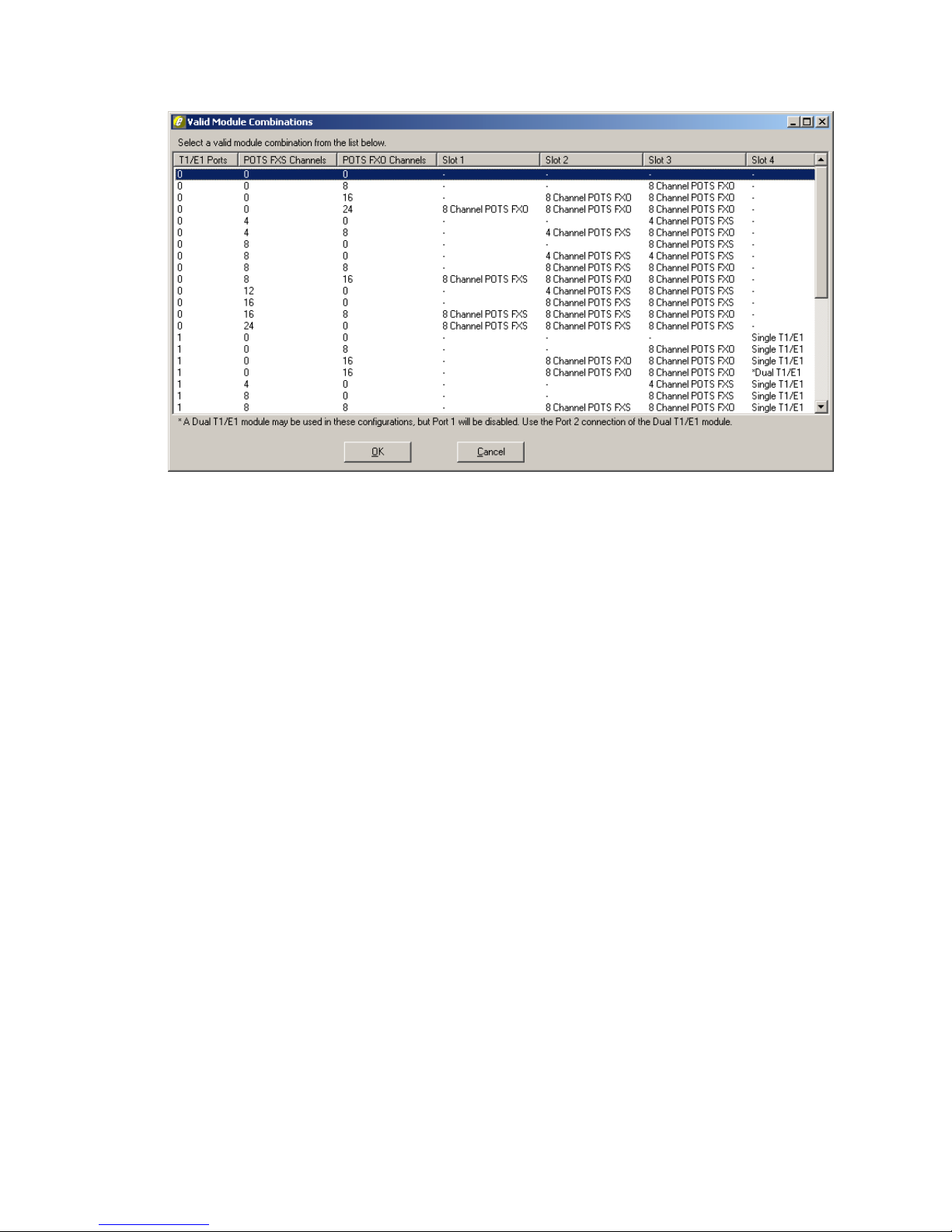
The Module Matrix Wizard button on the Unit screen (see Figure 14) can be used to
select valid module installation configurations. After clicking the Module Matrix
Wizard button, the Valid Module Combination dialog box is displayed, as shown in
Figure 15.
40-400-00065, Rev. E
19
TSP Edge User’s Manual
Figure 15. Module Matrix Wizard
Selecting a module combination in the Valid Module Combination dialog box and
then clicking OK sets all of the card types on the Unit screen. For more information,
see “Installing Hardware Modules” on page 11.
After configuring the card types, click OK on the Unit screen.
Newer Software Versions
If the Edge software version on the PC is newer than the code in the unit, a message
is displayed:
Newer code is available for unit ‘xxx’. Do you wish to
download to your unit now? Note: You must have a network
connection to the unit to download.
The Edge must have an Ethernet connection and an IP address assigned for the
download to be successful. Click No if this has not been done and follow the
instructions in the next subsection. Once the Edge is assigned an IP address,
download the newer version to the unit by clicking OK on the Unit screen or by
selecting Initialize on the Units menu. This can be done with either the Serial or
Network Connection selected on the General tab of the Unit screen.
If it’s indicated that the code in the Edge is newer than that on the PC, download the
latest version of the software from the Teltone website (www.teltone.com).
40-400-00065, Rev. E
20
 Loading...