

Teltone TSP Base User Manual
Telecom
Simulation
Platform
User’s Manual
Part No.: 40-400-00049
Revision: J

Copyright Notice
Copyright © 2001 Teltone Corporation
All Rights Reserved
Trademarks
Teltone is registered trademarks of Teltone Corporation.
TSP is a trademark of Teltone Corporation.
Windows is a registered trademark of Microsoft Corporation.
Other company and product names may be trademarks or
registered trademarks of their respective owners.
Teltone Corporation
22116 – 23
rd
Drive SE
Bothell, Washington 98021-4413 USA
Customer Service: 425-951-3388
Technical Support: 425-951-3390
Fax: 425-487-2288
Email: info@teltone.com
Website: www.teltone.com

Contents
IMPORTANT USER SAFETY INSTRUCTIONS. . . . . . . . . . . . . . . . . . . . . . . . . . . . . . . . . . . . . . vi
REGULATORY COMPLIANCE . . . . . . . . . . . . . . . . . . . . . . . . . . . . . . . . . . . . . . . . . . . . . . . . . . vi
Overview . . . . . . . . . . . . . . . . . . . . . . . . . . . . . . . . . . . . . . . . . . . . . . . . . . . . . . . . . . . . . . . . . . . . 1
Standard Features (TSP-Base). . . . . . . . . . . . . . . . . . . . . . . . . . . . . . . . . . . . . . . . . . . . . . . . 1
Hardware Options . . . . . . . . . . . . . . . . . . . . . . . . . . . . . . . . . . . . . . . . . . . . . . . . . . . . . . . . . . 2
Software Options. . . . . . . . . . . . . . . . . . . . . . . . . . . . . . . . . . . . . . . . . . . . . . . . . . . . . . . . . . . 2
System Requirements. . . . . . . . . . . . . . . . . . . . . . . . . . . . . . . . . . . . . . . . . . . . . . . . . . . . . . .2
Power Requirements . . . . . . . . . . . . . . . . . . . . . . . . . . . . . . . . . . . . . . . . . . . . . . . . . . . . 2
Operating System Requirements . . . . . . . . . . . . . . . . . . . . . . . . . . . . . . . . . . . . . . . . . . . 3
Connections . . . . . . . . . . . . . . . . . . . . . . . . . . . . . . . . . . . . . . . . . . . . . . . . . . . . . . . . . . .3
Simulation Interfaces . . . . . . . . . . . . . . . . . . . . . . . . . . . . . . . . . . . . . . . . . . . . . . . . . . . . 4
4 and 8 Channel POTS Modules . . . . . . . . . . . . . . . . . . . . . . . . . . . . . . . . . . . . . . . . . . . 6
Getting Started . . . . . . . . . . . . . . . . . . . . . . . . . . . . . . . . . . . . . . . . . . . . . . . . . . . . . . . . . . . . . . . 7
Check your TSP package . . . . . . . . . . . . . . . . . . . . . . . . . . . . . . . . . . . . . . . . . . . . . . . . . . . . 7
Optional Hardware . . . . . . . . . . . . . . . . . . . . . . . . . . . . . . . . . . . . . . . . . . . . . . . . . . . . . . 7
Optional Software Modules . . . . . . . . . . . . . . . . . . . . . . . . . . . . . . . . . . . . . . . . . . . . . . . 7
Configuring the TSP Hardware/Software . . . . . . . . . . . . . . . . . . . . . . . . . . . . . . . . . . . . . . . . . . . 8
Module Interface Matrix (Required Set-up) . . . . . . . . . . . . . . . . . . . . . . . . . . . . . . . . . . . . . . . 8
Basic Hardware setup . . . . . . . . . . . . . . . . . . . . . . . . . . . . . . . . . . . . . . . . . . . . . . . . . . . 8
Power up the TSP . . . . . . . . . . . . . . . . . . . . . . . . . . . . . . . . . . . . . . . . . . . . . . . . . . . . . . . . . . 8
Software Installation Instructions . . . . . . . . . . . . . . . . . . . . . . . . . . . . . . . . . . . . . . . . . . . . . . 9
Operational Strategy . . . . . . . . . . . . . . . . . . . . . . . . . . . . . . . . . . . . . . . . . . . . . . . . . . . . . . . . 9
Quick Start . . . . . . . . . . . . . . . . . . . . . . . . . . . . . . . . . . . . . . . . . . . . . . . . . . . . . . . . . . . . . . . 9
Hardware and Software Setup . . . . . . . . . . . . . . . . . . . . . . . . . . . . . . . . . . . . . . . . . . . . . 9
Units Configuration . . . . . . . . . . . . . . . . . . . . . . . . . . . . . . . . . . . . . . . . . . . . . . . . . . . . . 10
Module Configuration . . . . . . . . . . . . . . . . . . . . . . . . . . . . . . . . . . . . . . . . . . . . . . . . . . . 10
Templates Configuration . . . . . . . . . . . . . . . . . . . . . . . . . . . . . . . . . . . . . . . . . . . . . . . . 11
Control Sets Configuration . . . . . . . . . . . . . . . . . . . . . . . . . . . . . . . . . . . . . . . . . . . . . . . 11
Simulation Types. . . . . . . . . . . . . . . . . . . . . . . . . . . . . . . . . . . . . . . . . . . . . . . . . . . . . . . . . . 12
End-to-End Calls . . . . . . . . . . . . . . . . . . . . . . . . . . . . . . . . . . . . . . . . . . . . . . . . . . . . . . 12
Call Originate and Call Terminate . . . . . . . . . . . . . . . . . . . . . . . . . . . . . . . . . . . . . . . . . 13
Programming the TSP . . . . . . . . . . . . . . . . . . . . . . . . . . . . . . . . . . . . . . . . . . . . . . . . . . . . . . . . . 15
Telecom Simulation Platform (TSP) main screen . . . . . . . . . . . . . . . . . . . . . . . . . . . . . . . . . 15
Tree Display . . . . . . . . . . . . . . . . . . . . . . . . . . . . . . . . . . . . . . . . . . . . . . . . . . . . . . . . . . 15
Information Section. . . . . . . . . . . . . . . . . . . . . . . . . . . . . . . . . . . . . . . . . . . . . . . . . . . . . 15
Control Set Enables . . . . . . . . . . . . . . . . . . . . . . . . . . . . . . . . . . . . . . . . . . . . . . . . . . . . 16
Units . . . . . . . . . . . . . . . . . . . . . . . . . . . . . . . . . . . . . . . . . . . . . . . . . . . . . . . . . . . . . . . . . . . 16
Serial Connection . . . . . . . . . . . . . . . . . . . . . . . . . . . . . . . . . . . . . . . . . . . . . . . . . . . . . . 17
40-400-00049, Rev. J Page iii

Telecom Simulation Platform
Templates . . . . . . . . . . . . . . . . . . . . . . . . . . . . . . . . . . . . . . . . . . . . . . . . . . . . . . . . . . . . . . . 29
Control Sets . . . . . . . . . . . . . . . . . . . . . . . . . . . . . . . . . . . . . . . . . . . . . . . . . . . . . . . . . . . . . 34
Event Log Screen . . . . . . . . . . . . . . . . . . . . . . . . . . . . . . . . . . . . . . . . . . . . . . . . . . . . . . . . . . . . 43
Options Screen . . . . . . . . . . . . . . . . . . . . . . . . . . . . . . . . . . . . . . . . . . . . . . . . . . . . . . . . . . . . . . 45
TSP Diagnostics . . . . . . . . . . . . . . . . . . . . . . . . . . . . . . . . . . . . . . . . . . . . . . . . . . . . . . . . . . . . . 46
TSP Trace . . . . . . . . . . . . . . . . . . . . . . . . . . . . . . . . . . . . . . . . . . . . . . . . . . . . . . . . . . . . . . . . . . 48
Primary Rate ISDN Software Module (TSP-PRI) . . . . . . . . . . . . . . . . . . . . . . . . . . . . . . . . . . . . 49
T1 Tab. . . . . . . . . . . . . . . . . . . . . . . . . . . . . . . . . . . . . . . . . . . . . . . . . . . . . . . . . . . . . . . . . . 49
PRI Tab . . . . . . . . . . . . . . . . . . . . . . . . . . . . . . . . . . . . . . . . . . . . . . . . . . . . . . . . . . . . . . . . . 51
Channels Tab . . . . . . . . . . . . . . . . . . . . . . . . . . . . . . . . . . . . . . . . . . . . . . . . . . . . . . . . . . . . 52
Troubleshooting. . . . . . . . . . . . . . . . . . . . . . . . . . . . . . . . . . . . . . . . . . . . . . . . . . . . . . . . . . . . . . 54
Icon Legend. . . . . . . . . . . . . . . . . . . . . . . . . . . . . . . . . . . . . . . . . . . . . . . . . . . . . . . . . . . . . . . . . 57
Authorization Code . . . . . . . . . . . . . . . . . . . . . . . . . . . . . . . . . . . . . . . . . . . . . . . . . . . . . 18
Software Updates . . . . . . . . . . . . . . . . . . . . . . . . . . . . . . . . . . . . . . . . . . . . . . . . . . . . . . 19
Network Connection . . . . . . . . . . . . . . . . . . . . . . . . . . . . . . . . . . . . . . . . . . . . . . . . . . . . 19
Slot Tabs . . . . . . . . . . . . . . . . . . . . . . . . . . . . . . . . . . . . . . . . . . . . . . . . . . . . . . . . . . . .21
Single T1/E1 and Dual T1/E1 Card Types . . . . . . . . . . . . . . . . . . . . . . . . . . . . . . . . . . . 21
The 4 and 8 Channel POTS Card Types . . . . . . . . . . . . . . . . . . . . . . . . . . . . . . . . . . . . 24
Channels Tab . . . . . . . . . . . . . . . . . . . . . . . . . . . . . . . . . . . . . . . . . . . . . . . . . . . . . . . . . 25
Channel Configuration Wizard . . . . . . . . . . . . . . . . . . . . . . . . . . . . . . . . . . . . . . . . . . . . 27
T1/E1 Alarms . . . . . . . . . . . . . . . . . . . . . . . . . . . . . . . . . . . . . . . . . . . . . . . . . . . . . . . . . 28
Type Tab . . . . . . . . . . . . . . . . . . . . . . . . . . . . . . . . . . . . . . . . . . . . . . . . . . . . . . . . . . . . 29
Channel Protocols . . . . . . . . . . . . . . . . . . . . . . . . . . . . . . . . . . . . . . . . . . . . . . . . . . . . . 30
Timings Tab . . . . . . . . . . . . . . . . . . . . . . . . . . . . . . . . . . . . . . . . . . . . . . . . . . . . . . . . . . 32
Signaling Tab . . . . . . . . . . . . . . . . . . . . . . . . . . . . . . . . . . . . . . . . . . . . . . . . . . . . . . . . . 33
Control Set Type Field . . . . . . . . . . . . . . . . . . . . . . . . . . . . . . . . . . . . . . . . . . . . . . . . . . 35
Template Field . . . . . . . . . . . . . . . . . . . . . . . . . . . . . . . . . . . . . . . . . . . . . . . . . . . . . . . . 36
Channel Assignments. . . . . . . . . . . . . . . . . . . . . . . . . . . . . . . . . . . . . . . . . . . . . . . . . . . 37
Executing a Simulation . . . . . . . . . . . . . . . . . . . . . . . . . . . . . . . . . . . . . . . . . . . . . . . . . . 39
End-to-End Control Set Example . . . . . . . . . . . . . . . . . . . . . . . . . . . . . . . . . . . . . . . . . . 41
Alerts Tab . . . . . . . . . . . . . . . . . . . . . . . . . . . . . . . . . . . . . . . . . . . . . . . . . . . . . . . . . . . .45
Upgrades Tab. . . . . . . . . . . . . . . . . . . . . . . . . . . . . . . . . . . . . . . . . . . . . . . . . . . . . . . . . 45
Clock. . . . . . . . . . . . . . . . . . . . . . . . . . . . . . . . . . . . . . . . . . . . . . . . . . . . . . . . . . . . . . . . 50
Framing . . . . . . . . . . . . . . . . . . . . . . . . . . . . . . . . . . . . . . . . . . . . . . . . . . . . . . . . . . . . .50
Line Coding . . . . . . . . . . . . . . . . . . . . . . . . . . . . . . . . . . . . . . . . . . . . . . . . . . . . . . . . . . 50
PCM Encoding . . . . . . . . . . . . . . . . . . . . . . . . . . . . . . . . . . . . . . . . . . . . . . . . . . . . . . . . 51
Switch Type . . . . . . . . . . . . . . . . . . . . . . . . . . . . . . . . . . . . . . . . . . . . . . . . . . . . . . . . . . 51
Simulation. . . . . . . . . . . . . . . . . . . . . . . . . . . . . . . . . . . . . . . . . . . . . . . . . . . . . . . . . . . .51
Subaddress . . . . . . . . . . . . . . . . . . . . . . . . . . . . . . . . . . . . . . . . . . . . . . . . . . . . . . . . . . 52
Calling and Called Number. . . . . . . . . . . . . . . . . . . . . . . . . . . . . . . . . . . . . . . . . . . . . . . 52
Templates. . . . . . . . . . . . . . . . . . . . . . . . . . . . . . . . . . . . . . . . . . . . . . . . . . . . . . . . . . . .52
Page iv

Contents
Appendix 1 Flowcharts . . . . . . . . . . . . . . . . . . . . . . . . . . . . . . . . . . . . . . . . . . . . . . . . . . . . . . . . 58
Timings Tab for Analog LS, T1/E1 GS FXS, and T1/E1 LS FXS . . . . . . . . . . . . . . . . . . 58
Call Process Flowcharts for Analog LS, T1/E1 GS FXS or T1/E1 LS FXS . . . . . . . . . . 59
Timings Tab for E1 ITU Q.421 . . . . . . . . . . . . . . . . . . . . . . . . . . . . . . . . . . . . . . . . . . . . 61
Call Process Flowcharts for E1 ITU Q.421. . . . . . . . . . . . . . . . . . . . . . . . . . . . . . . . . . . 62
Timings Tab for T1/E1 GS FXO and T1/E1 LS FXO . . . . . . . . . . . . . . . . . . . . . . . . . . . 64
Timings Tab for T1/E1 Immediate Dial . . . . . . . . . . . . . . . . . . . . . . . . . . . . . . . . . . . . . . 65
Call Terminate T1/E1 Immediate . . . . . . . . . . . . . . . . . . . . . . . . . . . . . . . . . . . . . . . . . . 66
Timings tab for T1/E1 Delay Dial and T1/E1 Wink Start. . . . . . . . . . . . . . . . . . . . . . . . . 67
Call Process Flow Charts for T1/E1 Wink and Delay Dial . . . . . . . . . . . . . . . . . . . . . . . 69
Timings Tab for T1 PRI (CPE) . . . . . . . . . . . . . . . . . . . . . . . . . . . . . . . . . . . . . . . . . . . . 70
Timings Tab for T1 PRI (Network) . . . . . . . . . . . . . . . . . . . . . . . . . . . . . . . . . . . . . . . . . 71
Glossary of Terms . . . . . . . . . . . . . . . . . . . . . . . . . . . . . . . . . . . . . . . . . . . . . . . . . . . . . . . . . . . . 73
References . . . . . . . . . . . . . . . . . . . . . . . . . . . . . . . . . . . . . . . . . . . . . . . . . . . . . . . . . . . . . . . . . 77
Revision History. . . . . . . . . . . . . . . . . . . . . . . . . . . . . . . . . . . . . . . . . . . . . . . . . . . . . . . . . . . . . . 78
Warranty and Service . . . . . . . . . . . . . . . . . . . . . . . . . . . . . . . . . . . . . . . . . . . . . . . . . . . . . . . . . 79
Warranty Information. . . . . . . . . . . . . . . . . . . . . . . . . . . . . . . . . . . . . . . . . . . . . . . . . . . . . . .79
Return Procedures . . . . . . . . . . . . . . . . . . . . . . . . . . . . . . . . . . . . . . . . . . . . . . . . . . . . . . . .79
Technical Assistance . . . . . . . . . . . . . . . . . . . . . . . . . . . . . . . . . . . . . . . . . . . . . . . . . . . . . . 79
Maintenance . . . . . . . . . . . . . . . . . . . . . . . . . . . . . . . . . . . . . . . . . . . . . . . . . . . . . . . . . . . . . 79
Cleaning . . . . . . . . . . . . . . . . . . . . . . . . . . . . . . . . . . . . . . . . . . . . . . . . . . . . . . . . . . . . .79
Servicing. . . . . . . . . . . . . . . . . . . . . . . . . . . . . . . . . . . . . . . . . . . . . . . . . . . . . . . . . . . . . 79
Ordering Information . . . . . . . . . . . . . . . . . . . . . . . . . . . . . . . . . . . . . . . . . . . . . . . . . . . . . . . . . . 80
Specifications . . . . . . . . . . . . . . . . . . . . . . . . . . . . . . . . . . . . . . . . . . . . . . . . . . . . . . . . . . . . . . . 81
Index . . . . . . . . . . . . . . . . . . . . . . . . . . . . . . . . . . . . . . . . . . . . . . . . . . . . . . . . . . . . . . . . . . . . . . 83
40-400-00049, Rev. J Page v

Telecom Simulation Platform
IMPORTANT USER SAFETY INSTRUCTIONS
When using your equipment, basic safety precautions should always be followed to reduce the risk of fire, electric
shock, and injury to persons, including the following:
1. Read and understand all instructions.
2. Follow all warnings and instructions marked on the product.
3. This product should be operated only from the type of power source indicated on the marking label. If you are
not sure of the type of power supply, consult your dealer or local power company. Product designed for indoor use
only.
4. To reduce the risk of electric shock, do not disassemble this product, but take it to a qualified serviceman when
some service or repair work is required. Opening or removing covers may expose you to dangerous voltages or
other risks. Incorrect reassembly can cause electric shock when the appliance is subsequently used.
5. If the product does not operate normally by following the operating instructions, or if the product has been
dropped or the cabinet has been damaged, or if the product exhibits a distinct change in performance; refer
servicing to qualified service personnel.
6. If this product is used in a manner other than specified in this manual, the protection provided by the product
may be impaired.
7. The IEC 320 connecter (power input) is the main power disconnect point, for the purpose of removing power
from the unit. Pull the power cord away from the connector to assure power disconnect.
8. Adequate air flow must be maintained in order for the unit to operate correctly. Do not wrap the unit in blankets,
paper, or other material that may impede ventilation.
REGULATORY COMPLIANCE
FCC Part 15 : This equipment has been tested and found to comply with the limits for a Class A digital device,
pursuant to Part 15 of the FCC Rules. These limits are designed to provide reasonable protection against harmful
interference in a residential installation. This equipment generates, uses, and can radiate radio frequency energy
and, if not installed and used in accordance with the instructions, may cause harmful interference to radio
communications. However, there is no guarantee that interference will not occur in a particular installation. If this
equipment does cause harmful interference to radio or television reception, which can be determined by turning
the equipment off and on, the user is encouraged to try to correct the interference by one or more of the following
measures:
·
Reorient or relocate the receiving antenna.
·
Increase the separation between the equipment and receiver.
·
Connect the equipment to an outlet on a circuit different from that to which the receiver is
connected.
·
Consult the dealer or an experienced radio/TV technician for help.
The Installation Category (OVER VOLTAGE CATEGORY) for this device is II and it is designed to be safe under
POLLUTION DEGREE 2, per IEC 1010-1: 1990 specifications.
Page vi

Overview
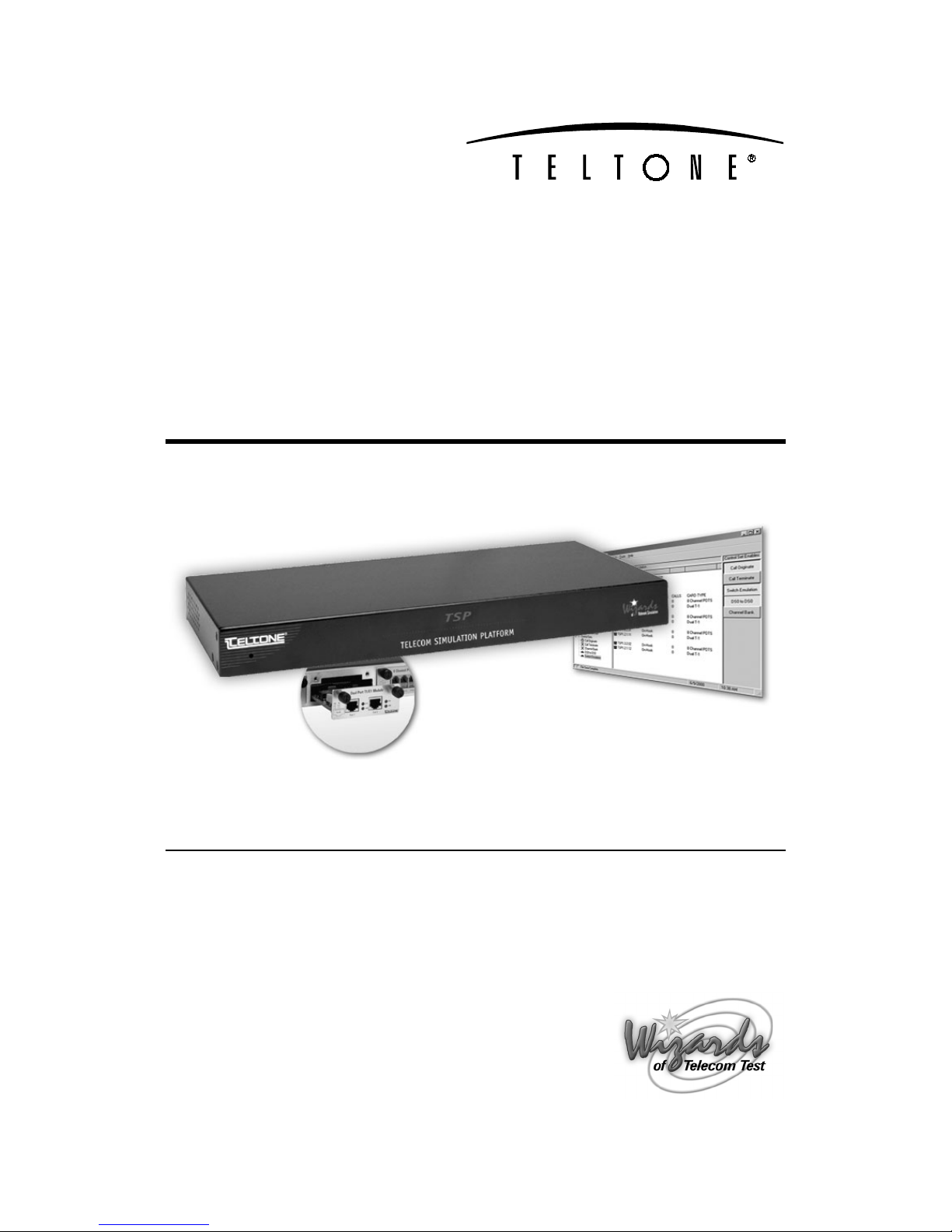
The Teltone TSP (Telecom Simulation Platform) is a combined hardware and software platform
used to simulate connections to different telephony interfaces. These include T1, E1, and Analog
POTS, and in the future, other interfaces. The AC power input is universal, accepting 90 to 250
VAC, from 43 to 63 Hz. An RS-232 port connection is used to configure the TSP.
Standard Features (TSP-Base)
Base unit for configuring with optional hardware modules
·
Upgradeable software and hardware modular design
·
Able to connect multiple TSP’s to a single computer
·
Analog POTS and T1/E1 simulation in the same system
·
Operates under Windows 95/98/2000 or Windows NT
·
Programming and control can be done with either the serial or ethernet connection
·
Status Display provides current state for each channel (on/off-hook, ringing, etc)
·
Supports three call types
·
Originate – calls placed by the TSP to a connected device
·
Terminate – calls placed into the TSP by a connected device
·
End-to-End – calls placed through the TSP by one device to another
·
Call progress and DTMF signaling by playback of audio files
·
Event Logging of
·
On/off-hook
·
·
Ringing
·
Time to answer
·
Call duration
·
Errors such as T1/E1 loss of sync
·
Date/time of each event
·
Programmable Call Parameters
·
T1 channel type (robbed bit signaling): Loop Start, Ground Start, Immediate Dial, Wink
Start, Delay Dial
·
E1 channel signaling including: CAS Q.421 with DTMF Variation, Loop Start, Ground
Start, Wink, Immediate Dial, Delay Dial
·
CAMA or Tie Trunk operation
·
Programmable T1 and E1 signaling bit states for A, B, C & D bits
·
T1/E1 Clear channel “nailed up” 64 KB/s connection
·
Analog channel type: Loop Start only
·
Call Timing: Call Duration, Guard Time, Far-end Disconnect Time, Delay Before Audio
Message
·
Dial String: ANI/DNIS Transmit Digits –40 Digits, Phone Number –40 Digits.
·
Dial Tone: Enable, Delay Before, Length
·
Ringback: Enable, Duration
·
Bulk Call Generation
·
Diagnostics with ability to place channels in different signaling states and shows the signaling
bit states on T1/E1
·
Trace for detailed call progress of a channel
40-400-00049, Rev. J Page 1
Telecom Simulation Platform
Hardware Options
·
·
·
·
Software Options
TSP-PRI (Primary Rate ISDN)
This option includes the standard TSP features plus:
·
·
·
TSP Single T1/E1 module
TSP Dual T1/E1 module
TSP 4 Channel POTS module
TSP 8 Channel POTS module
Multiple switch types, which include:
US National ISDN-2
·
AT&T 4ESS
·
AT&T 5ESS
·
NT DMS-100/250
·
Simulates CPE end or Network end
Provides the following Supplementary Services:
Direct dialing in (DDI)
·
Subaddressing
·
Delivery of Called and Caller number (CLIP)
·
Delivery of Type of Address and Numbering Plan
·
System Requirements
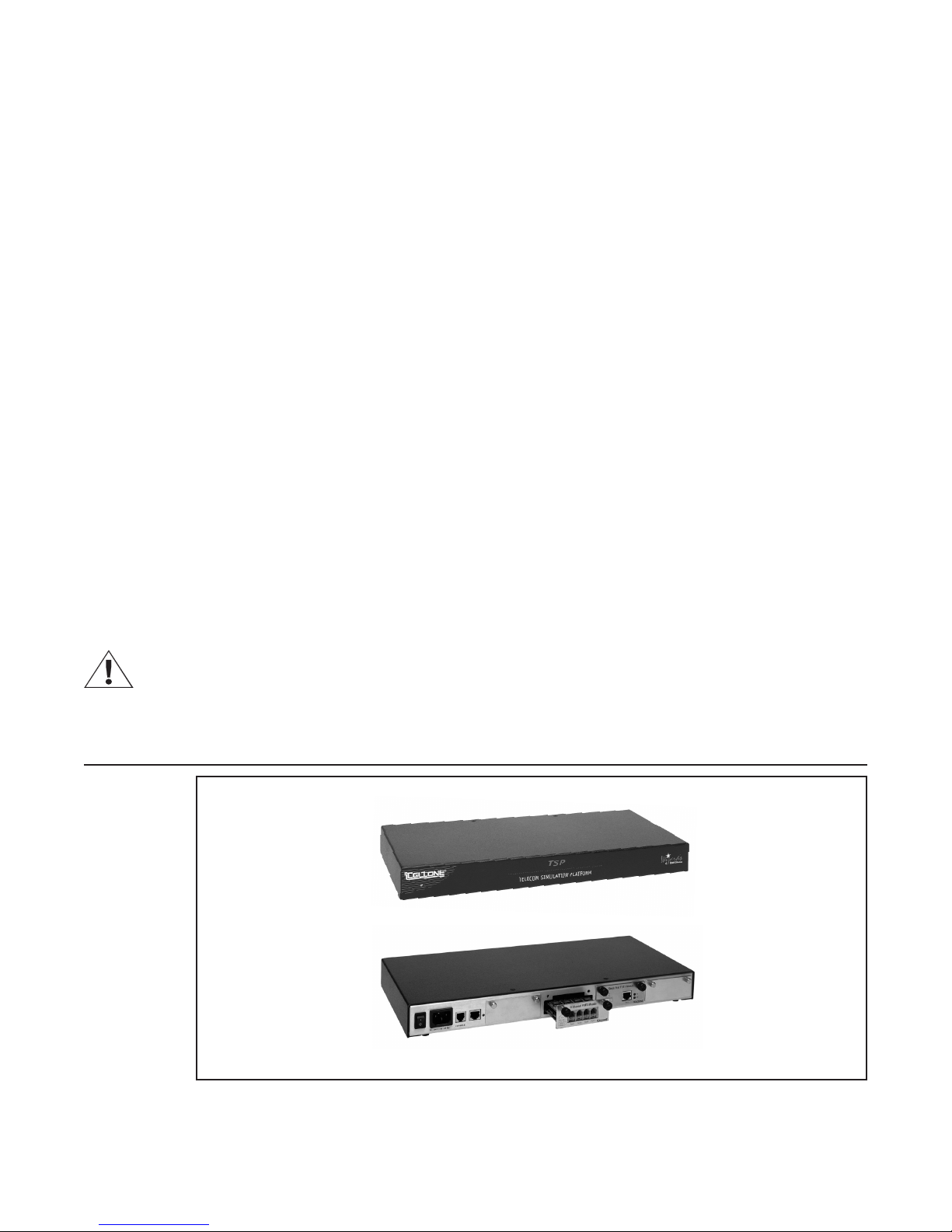
Power Requirements
AC operating power must be within 90 to 250 Volts AC and the operating frequency from 43 to 63
Hz. A standard North American plug is provided with the unit, although the TSP base unit uses an
industry standard IEC three prong connector so that almost any international power plug can be
used.
Figure 1 TSP-A-01
Page 2
Overview
Operating System Requirements
The PC Configuration software will operate on Windows 95/98/2000 and Windows NT. The
following minimum disk storage capacities are required for the basic installation and storage of
saved files:
6 Mb required on the disk with the Windows operating system
4 Mb required on the disk the application is installed on
7 Mb additional required to install the Adobe Acrobat reader
Connections
Configuring and control of the TSP can be done with either a serial connection to a PC or with an
Ethernet connection directly to a PC or to a LAN. It is necessary to use the serial connection to
initially program the IP for the Ethernet connection.
Important
When using the T1/E1 module in T1-PRI mode, the network connection must be used for
programming and control; the serial connection is not allowed. This allows for enhanced
messaging during PRI operation.
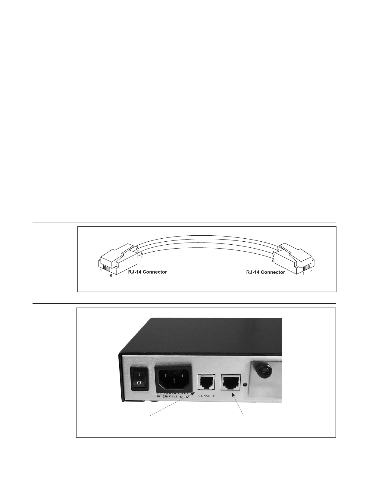
Serial connection
The connection is an RJ-11 port using an RJ-14 standard on the TSP chassis, mating to a DB-9
or DB-25 connector (on the PC) and supports control leads Tx Data, Rx Data, and Ground. Refer
to Figure 2 for cable pinouts. Refer to Figure 3 for port connections.
Important
Initial programming of the TSP must be done with this connection
Figure 2 Serial Cable RJ-14 to RJ-14
Figure 3 RJ-14 Port Connections
Serial Connection Ethernet Connection
40-400-00049, Rev. J Page 3

Telecom Simulation Platform
Ethernet connection
The network connection is a 10/100 base T using an RJ-45 connector. This connection is
necessary for downloading voice messages and software updates to the TSP. The Ethernet cable
provided is a cross-over cable and is only used when connecting directly to a PC. Refer to Figure
4 for cable pinouts. Refer to Figure 3 for port connections. See Network Connection in the Units
section for more details.
Figure 4 Ethernet Cross-over cable
RJ-45 Connector 1 RJ-45 Connector 2
1 Pair 2 (T2) Tx + 3 White/Orange Rx +
2 Pair 2 (R2) Tx - 6 Orange Rx -
3 Pair 3 (T3) Rx + 1 White/Green Tx +
4 Pair 1 (R1) 4 Blue
5 Pair 1 (T1) 5 White/Blue
6 Pair 3 (R3) Rx - 2 Green Tx -
7 Pair 4 (T4) 7 White/Brown
8 Pair 4 (R4) 8 Brown
Simulation Interfaces
Single and Dual T1/E1 Modules
Cable requirements, Pinouts, Technical Specs
·
The Single T1/E1 and Dual T1/E1 interface modules support a line build-out of either 0-133 ft,
134-266 ft, 267-399 ft, or 400-533 ft for connection to real cable installations. An alternate
choice for line build-out is defining the loss characteristics of -7.5 dB, -15 dB, or -22.5 dB.
Physical connection is via an RJ-45 configured to RJ-48C standard (pin 1- Rx ring, Pin 2- Rx
tip, pin 4- Tx ring, pin 5- Tx tip). Framing options include D4 or ESF for T1. E1 features
include signaling options of FAS, CAS with the option for CRC-4. Line Coding options are
AMI with the option for B8ZS on T1 and HDB3 for E1. Clocking options are either internal or
external.
Page 4
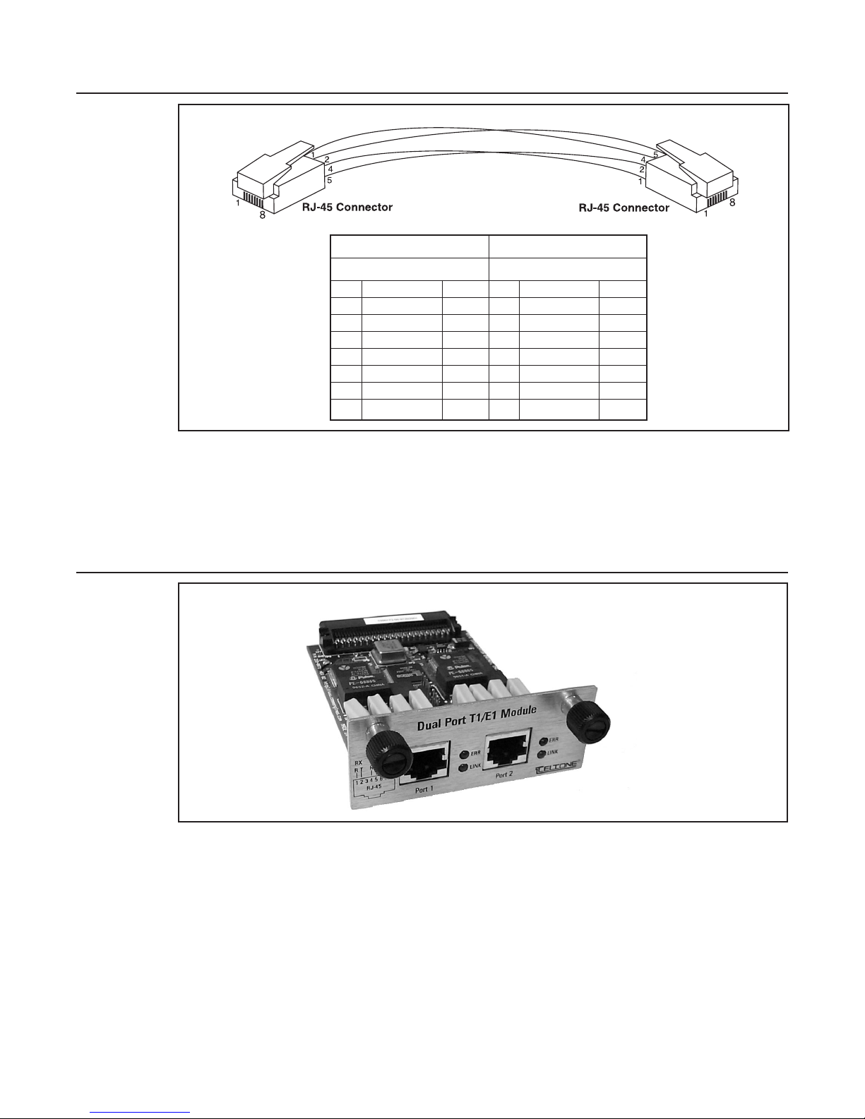
Figure 5 T1/E1 Cable
DTE DTE
Connector 1 RJ-45 Connector 2
RJ-45
1 White/Orange Rx Ring 4 White/Orange Tx Ring
2 Orange Rx Tip 5 Orange Tx Tip
3 White/Green NC 3 - NC
4 Blue Tx Ring 1 Blue Rx Ring
5 White/Blue Tx Tip 2 White/Blue Rx Tip
6 Green NC 6 - NC
7 White/Brown NC 7 - NC
8 Brown NC
8
Overview
Important:
A shielded T1/E1 cable must be used for the TSP to be FCC Part 15 compliant.
The Single T1/E1 Module looks like the Dual T1/E1 Module except there is only one port. See
Figure 6.
Figure 6 Dual T1/E1 Module
LINK This LED indicator shows that the T1/E1 link is active
ERR This LED indicator shows that an error has occurred
40-400-00049, Rev. J Page 5
Telecom Simulation Platform
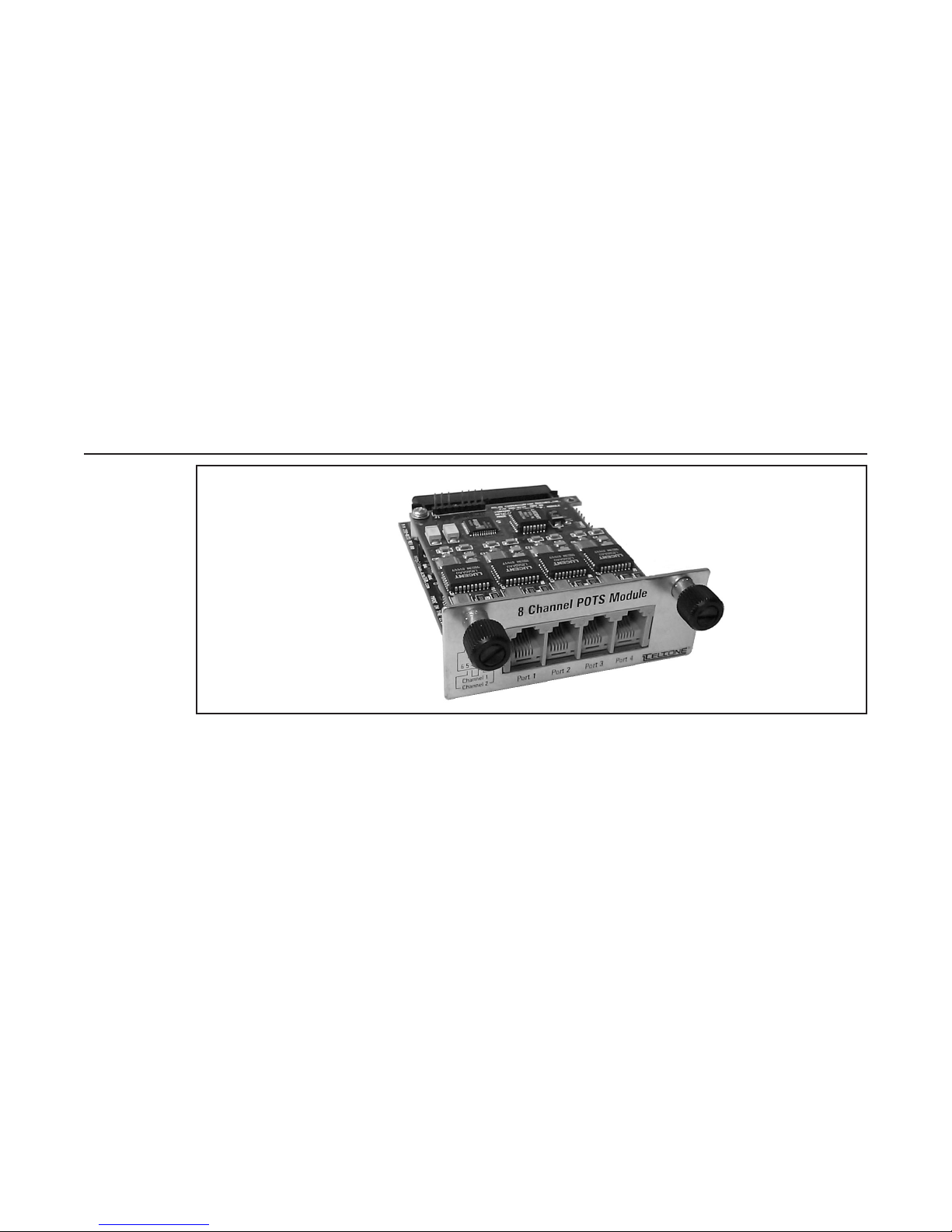
4 and 8 Channel POTS Modules
4 Channel POTS Module
Cable requirements, P inouts, Technical Specs
The 4 Channel POTS interface module will use industry standard RJ-11 jacks and the wiring
·
also meets industry standards, using Pins 3 and 4 for Tip and Ring. Pins 1,2,5, and 6 have no
connection.
The 4 channel POTS module is identical to the 8 channel module, except there is only 1 channel
available per port. See Figure 7.
8 Channel POTS Module
Cable Requirements, Pinouts, Technical Specs
The 8 Channel POTS interface module will use industry standard RJ-11 jacks and is wired to
·
RJ-14 standards, using Pins 3 and 4 for Tip & Ring for the first line, and pins 2 and 5 for Tip
& Ring for the second line. Pins 1 and 6 will have no connection.
Figure 7 8 Channel POTS Module
Page 6

Getting Started
Check your TSP package
When you receive your TSP (Telecom Simulation Platform), you will receive the following
components:
Your package should include the following items:
TSP-BASE-01 unit
·
120 VAC power cord
·
RJ-45 Ethernet cross over cable (gray cable, labeled)
·
RJ-14 - RS-232 cable (RJ-11 connector on each end)
·
RJ-14 - DB-9 adapter
·
RJ-14 - DB-25 adapter
·
Two RJ-45 - T1/E1 cables (yellow cable, labeled)
·
TSP Configuration Software (CD-ROM)
·
Product Registration Card
·
At least 1 Optional Hardware Module (purchased separately)
·
Optional Hardware
Single T1/E1 interface module
·
Dual T1/E1 interface module
·
4 Channel POTS interface module
·
·
8 Channel POTS interface module
·
Y-Cable Kit (set of 4)
Optional Software Modules
·
TSP-PRI, T1 Primary Rate ISDN software module
If any of the items you ordered are missing or damaged, contact Teltone’s Customer Service
department at 425-951-3388.
The TSP modules are ESD (electro-static discharge) sensitive devices and are shipped in static
shield packaging. Proper precautions are needed to avoid damaging them when handled. Teltone
Corporation requires any returned modules to be properly packaged in static shield packaging.
40-400-00049, Rev. J Page 7

Configuring the TSP Hardware/Software
Module Interface Matrix (Required Set-up)
Table 1 Module Interface Matrix
Slot 1 Slot 2 Slot 3 Slot 4
One Single- or Dual-T1/E1 module not used T1/E1 not used not used
One 4- or 8-Channel POTS module not used not used POTS not used
Two Single-T1/E1 modules (Note 1) not used T1/E1 T1/E1 not used
One Single- or Dual-T1/E1 module and one 4- or
8-Channel POTS module
Two 4- or 8-Channel POTS modules (Note 2) not used POTS POTS not used
Three 8-Channel POTS modules POTS POTS POTS not used
One Single- or Dual-T1/E1 module and two 8-Channel
POTS module (Note 3)
One Single- or Dual-T1/E1 module and three 8-Channel
POTS modules (Note 3)
Note 1: The TSP does not support two Dual T1/E1 modules.
Note 2: If using both a 4-Channel POTS and a 8-Channel POTS module, Teltone recommends placing the 4-Channel POTS module in
Note 3: A Single- or Dual-T1/E1 module can be used but only the second port of a Dual-T1/E1 module will be active if more than one
Slot 2 and the 8-Channel POTS module in Slot 3.
POTS module is installed. Port 1 of a Dual-T1/E1 module will be disabled.
not used T1/E1 POTS not used
not used POTS POTS T1/E1
POTS POTS POTS T1/E1
Slot count is 1-4 from left to right when looking at the back of the TSP.
Modules must be installed per the matrix before the TSP is powered on. Call setup scenarios that
are configured via the PC software are dependent upon the order in which modules are installed.
For example, configurations that are created when slot 2 has a T1/E1 module installed and slot 3
has a POTS module installed, will not be recognized as valid if the modules are moved to
different positions. Therefore it is always necessary to follow the required installation order
specified above. The TSP will give an error if the modules are not installed as required in the
matrix.
Basic Hardware setup
Before applying power to the TSP, install the optional modules per the matrix. Ensure they are
securely seated. Connect the CommPort cable (RJ-11 jack at both ends) to the unit at the jack
labeled Console. Connect the other end to the PC using the DB-9 or DB-25 adapter. For the
Ethernet connection, use the provided crossover cable (RJ-45 at both ends) if connecting directly
to the PC. If connecting to the network, a standard Ethernet cable will be needed.
Important
Before installing or removing a POTS module, connect a telephone set to any port of any POTS
module, power down the unit, and then go off-hook on the telephone set. This allows for voltage
dissipation from the base unit and prevents damage to the unit. An alternative procedure is to
power down the TSP for at least 30 minutes before installing or removing the module.
Power up the TSP
Before power-up ensure that the modules are seated firmly in the TSP to prevent damage.
The TSP uses a universal power supply that operates from 90 to 250 VAC, 43 to 63 Hz. Connect
the power cord and turn on the unit using the switch on the back of the unit.
Note:
Page 8
Grounding is assured by using the appropriate (approved) power cord.

Configuring the TSP/Hardware and Software
The green status LED on the front panel will indicate the status of the system. The LED should be
solid green. If the LED fails to light, disconnect power immediately and contact Teltone Technical
Support at 425-951-3390.
Important
Adequate airflow must be maintained in order for the unit to operate correctly. Do not wrap the
unit in blankets, paper or other material that may impede ventilation.
Software Installation Instructions
The TSP software is supplied on a CD-ROM disk and uses the common Windows setup routine.
Ensure you have the latest version (Version 2.5 at the time this was written) by going to the
Teltone web site, and verifying the version available under Software Downloads for the TSP or
call Technical Support 425-951-3390.
An autorun facility will initiate the installation process automatically when the CD-ROM is installed
into the disk drive. An alternative method to perform the installation is to insert the CD-ROM, then
select START, RUN, BROWSE, then choose your CD-ROM drive, and the file labeled
SETUP.EXE. Follow the on screen instructions.
Important
It will be necessary to obtain an Authorization Code from Teltone Customer Service after the first
Unit is created with the configuration software to enable testing with the TSP. Once the
Authorization Code is installed, the TSP can be used with any PC using the current configuration
software version. See Authorization Code in the Units section for complete instructions.
For information about the current and previous versions of the software, see page 78.
Operational Strategy
The TSP uses a GUI based configuration software program that allows a user to define the TSP
using Units, Templates, Control Sets, and Options. These parameters are saved as a Project
found on the File menu.
Quick Start
Note
The Unit definition defines the communications interface, the installed hardware and some
generic definitions of each module. The Templates define the channel operating characteristics
and timings. The Control Set definition defines the group(s) of individual channels and their
interactions. Once these items have been defined, a Control Set button will appear. When a
Control Set Enables button is selected, this begins the running of the particular application.
Configuration of the TSP via the Windows GUI is very flexible and allows the user to configure the
TSP in a straightforward manner. This section is to assist in configuring the TSP in minimal time
but is not intended to take the place of the rest of the manual. The basic process for setting up
the unit is described in the following subsections.
Hardware and Software Setup
1. Install the modules as required per the Module Interface Matrix section.
2. Connect the Serial and Ethernet cables according to the Basic Hardware Setup section.
The Ethernet connection is not necessary unless you are prompted that newer code is available
or you are using audio files. See Step 5 in “Units Configuration” if needed.
3. Ensure the modules are firmly seated and connect the power cord to the unit per the Power
up the TSP section. Turn on the TSP.
4. Follow the Software Installation Instructions section of the manual.
40-400-00049, Rev. J Page 9

Telecom Simulation Platform
5. Launch the Telecom Simulation Platform software.
6. Verify you are using the latest version of the configuration software (Version 2.5 at the time
this was written), by opening the program, going to the Help menu and choosing About TSP.
Confirm the latest version available by going to the Teltone web site at www.teltone.com, and
verifying the version under Software Downloads for the TSP or call Technical Support
425-951-3390.
Units Configuration
1. Choose New on the Units menu and name the TSP. The Units screen will default to Serial
connection.
2. Choose the CommPort of the PC that the TSP is connected to by clicking the arrow next to
None.
3. Use the Query Card Types button on the screen to set the program to match the cards that
are installed in the TSP.
4. Click OK on the Units screen. At this point, you will need to obtain an authorization code
before testing can be done with the TSP. Refer to the Authorization Code section of the
manual for instructions or call Teltone Corporation. (See step 6 in “Hardware and Software
Setup.”)
Note:
5. If you are prompted that "Newer code is available" choose No and follow the instructions in
the Software Updates section of the manual. Otherwise go to the next step.
6. Re-open the Units screen by going to the Unit menu and clicking the name given the unit at
the bottom of the drop-down menu.
Module Configuration
1. If a T1/E1 module is not being used skip to step 3. If using a T1/E1 module, click on the Slot
that corresponds to the position the card is installed on the Units screen and choose the Card
Mode by clicking the arrow. A T1 or E1 tab will appear which is used to set the parameters
accordingly for the equipment being tested.
T1-PRI Card Mode is an optional software module that can be purchased to enable the TSP for
this mode.
2. If you are not using T1-PRI, skip to the next step. If using T1-PRI mode, a PRI tab will
appear. Set the appropriate Switch Type and the Simulation, which is the end the TSP will be
simulating.
3. Configure the Channels tab for the T1/E1 and POTS modules on each slot. This is for setting
the optional (but not necessary, depending on the type of testing) Channel Configuration.
Each channel can be assigned a Phone Number (T1, E1 and POTS), Transmit Digits (i.e.
ANI and DNIS for T1 and E1), and Audio Message (the Network Connection must be
established). For T1-PRI, Subaddress, Called Number and Calling Number features are
available. See Channels Tab in the Units section of manual for more details.
Note:
The first number of the channel configuration corresponds to the slot the module is in. Each
physical port (or connector) in the module to which you connect equipment is the second
assigned number. The third number corresponds to the actual channel. Each "port" can have
one or more "channels". For instance, each T1 port has 24 channels. On an 8 channel POTS
module, each of the four ports has two channels (i.e., each connector has two analog phone
lines).
4. The Wizard button can be used to assign values to all the channels at once. See Channel
Configuration Wizard for more details.
5. Click OK to exit the Units screen.
Page 10

Configuring the TSP/Hardware and Software
Templates Configuration
1. Create Templates to configure the types of channels based on the modules being used (i.e.
Analog Loop Start template for POTS and T1 Wink Start template for T1/E1 modules). The
template will be associated with the channels to be tested when a Control Set is created.
Templates are created by going to the Templates menu and clicking New. (See the
Templates section, Type Tab for a list of protocols.)
2. Click the Channel Protocol arrow for a list of available protocols. Analog Loop Start is only
used for the POTS module. Create a template for the T1/E1 module and use the appropriate
T1 protocol (i.e. T1 Wink Start). Start by using the defaults for all the fields on the template.
Control Sets Configuration
1. Create a new “Control Set” by going to the Control Set menu and clicking New. A "Control
Set" tells the TSP how to function. This is where the individual channels are assigned to
Templates. Multiple Control Sets are allowed in a single TSP for greater flexibility.
2. Select the type of Control Set by clicking the Call Originate arrow. Calls made using the TSP
are defined as follows:
Call Originate - calls placed by the TSP to a connected device. The TSP will play a WAV file
·
after the call is connected if selected on the Channels tab on the Units screen.
Call Terminate - calls placed into the TSP by a connected device. The TSP will play a WAV
·
file after the call is connected if selected on the Channels tab on the Units screen.
The four control set types below are End-to-End, which are calls placed through the TSP by a
connected device to another device. See End-to-End Control Sets section for more details.
Note:
Note:
Dialed - You have the choice of using one or two templates. Any channel within this control
·
set can call to any other channel within the control set by dialing the telephone number
assigned on the Channels tab of the Units screen.
When using the Dialed control set type, the Templates used will need to be edited to use the
Dialed Default Timing Set on the Type tab. Go to the Template menu and choose the name
at the bottom of the drop down menu to edit.
·
Switch Emulation - connecting one channel to another. This connection is scripted and
occurs automatically once a call is initiated by an off-hook or a seizure.
·
Channel Bank - T1/E1 FXO LS to Analog LS or T1/E1 Clear Channel to Analog LS are the
only protocols that can be used.
·
DS0 to DS0 - T1/E1 Clear Channel Operation is the only protocol available.
3. Assign the Templates previously created to be used with the channels tested. Click the
Templates arrow on the Control Set screen and choose the Template names. Call Originate
and Call Terminate will only have one Template field while all other control sets have two
fields.
4. On the same screen, the channels are assigned by clicking the Edit Channels button. A
Channel Assignment screen will appear and the Availa ble Channels will be listed on the left
side of the screen. Select the channels to be tested by moving them from the left window to
the right window. Click OK and you will be returned to the Control Sets screen. See Channel
Assignments section for more details.
The Switch Emulation, Channel Bank and DS0 to DS0 control set types require the channels to
be paired side by side on the right side of the screen. The channel initiating the call will
automatically be connected to the channel it is paired with.
5. Program the Start and Stop times, if applicable. Once steps 3 through 6 are completed, click
the OK button. This will return you to the main TSP screen. See the Controls Sets section for
more details on Steps 1 through 5.
40-400-00049, Rev. J Page 11
Telecom Simulation Platform
6. Once the Control Sets have been defined, you can run your simulation by enabling it with the
Control Set Enables button from the main TSP screen.
Simulation Types
The three basic types of calls are End-to-End, Call Originate, and Call Terminate. End-to-End
calls are similar to calls placed through any switch. Calls are originated on one end and are
terminated on the other end. However, in some applications, you may want to simulate incoming
traffic to a connected device, these calls are originated from within the TSP. You may also want
to monitor outgoing traffic from a connected device, these calls are Terminated into the TSP.
End-to-End Calls
End-to-End calls are ones where one channel is connected to another. They are initiated by an
external device connected to the TSP, attempting to make a connection to another external
device. For example, calling from one modem to another on a pair of POTS connections, or from
a POTS connection to a T1 modem bank for V.90 modem testing. A T1/E1 Clear Channel
application is where a single channel operates as a 64 KB/s pipe, with no framing or control bits
in the data stream. The channel is cross-connected to another T1/E1 Clear Channel via the
Control Set. Dialed, Channel Bank, DS0 to DS0 (for Clear Channel operation only) and Switch
Emulation are the types of End-to-End Control Sets used by the TSP.
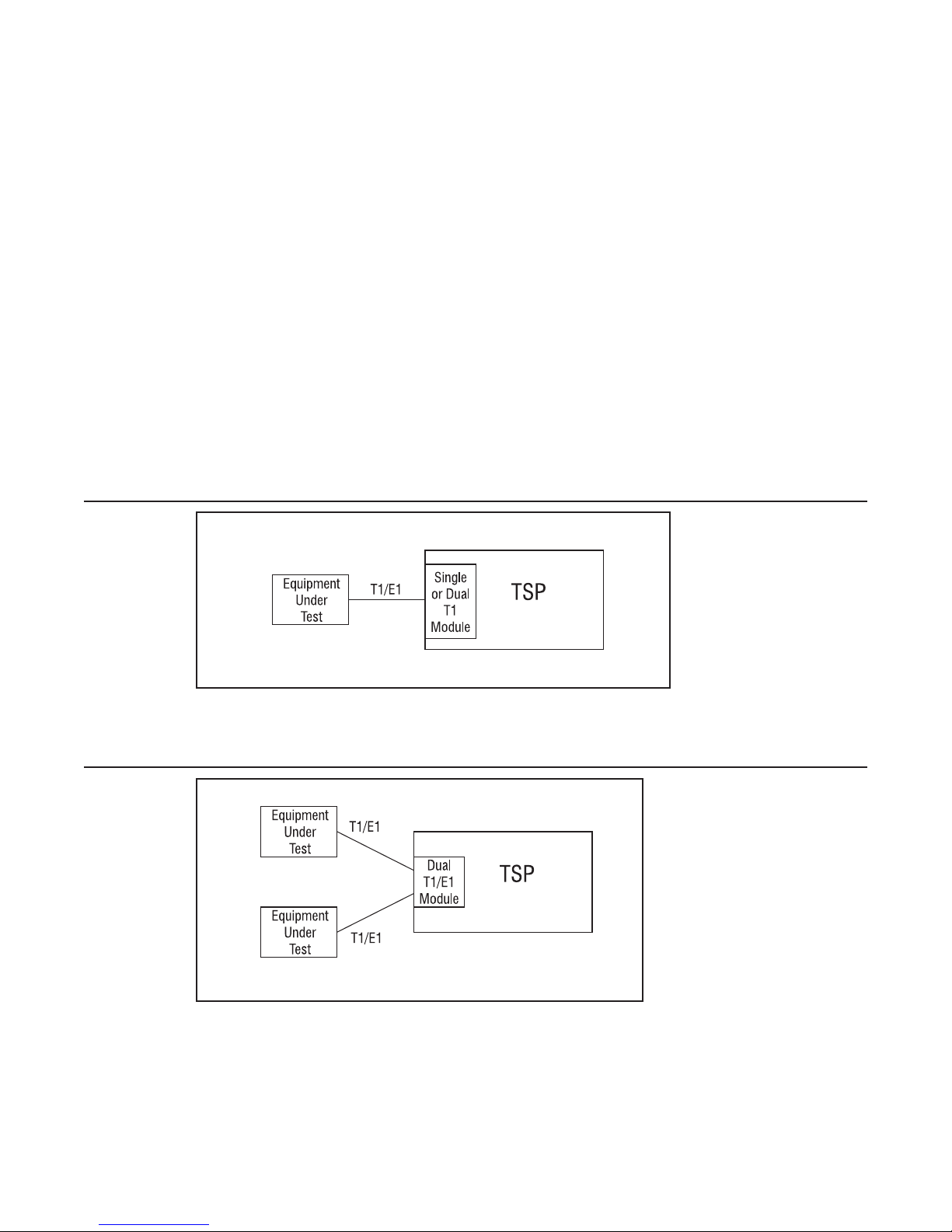
Figure 8 Single T1/E1, End-to-End
The TSP cross connects a channel on the T1/E1 to another channel on the same T1/E1.
Figure 9 Dual T1/E1 Block End-to-End
The TSP cross connects a channel on the first T1/E1 to any channel on the second T1/E1.
Page 12
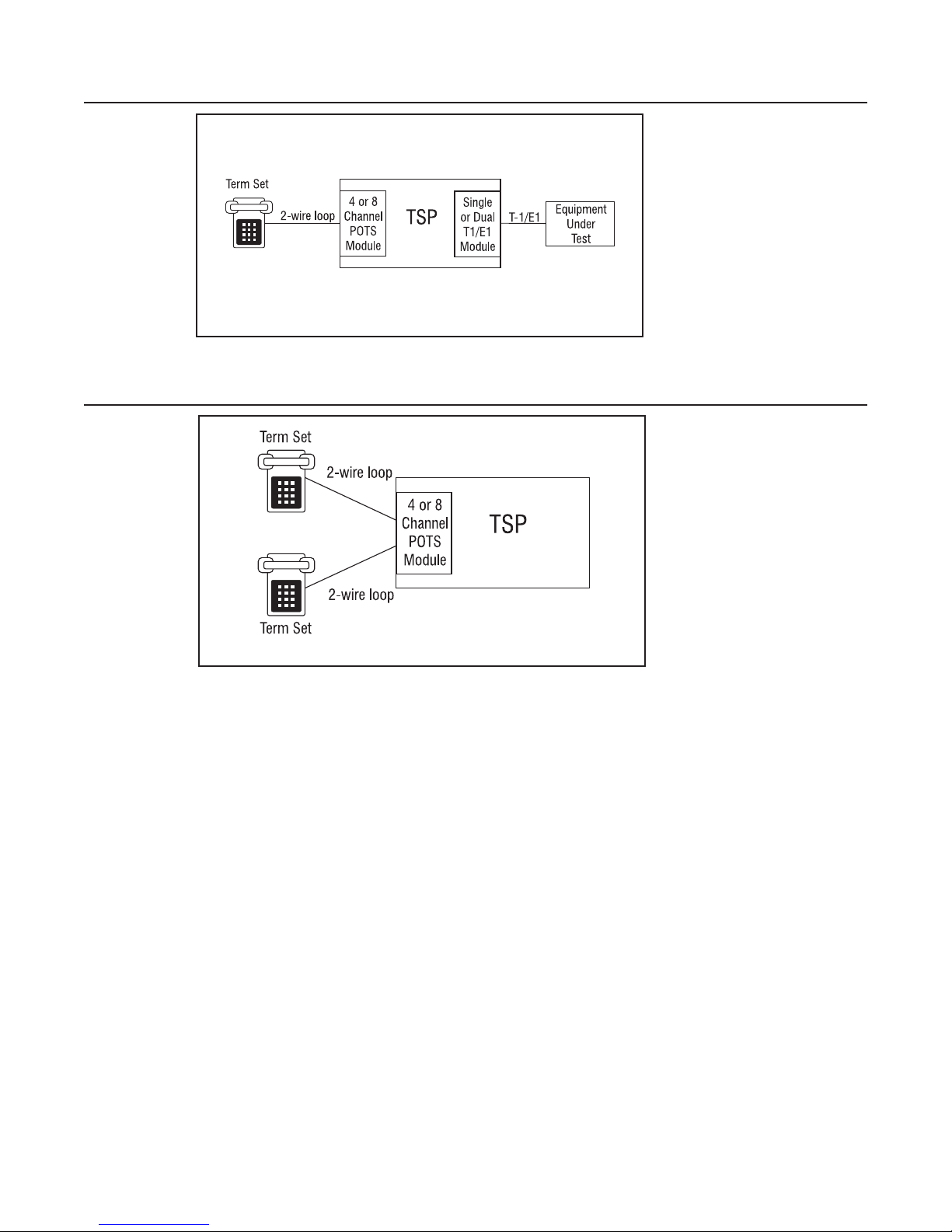
Figure 10 Analog LS to T1/E1 End-to-End
The TSP connects an Analog Loop Start channel to a T1/E1 channel.
Figure 11 Analog LS to Analog LS End-to-End
Configuring the TSP/Hardware and Software
The TSP connects an Analog Loop Start channel to another Analog Loop Start channel.
Call Originate and Call Terminate
The TSP generates calls to the equipment under test in Call Originate mode. Call Terminate
mode is where the TSP receives calls from the equipment under test. In both cases, the TSP will
count the calls, and display the calls as completed, unanswered, or busy in the event log. Once
the calls are established; a WAV file can be programmed to play to indicate that a call has taken
place.
40-400-00049, Rev. J Page 13
Telecom Simulation Platform
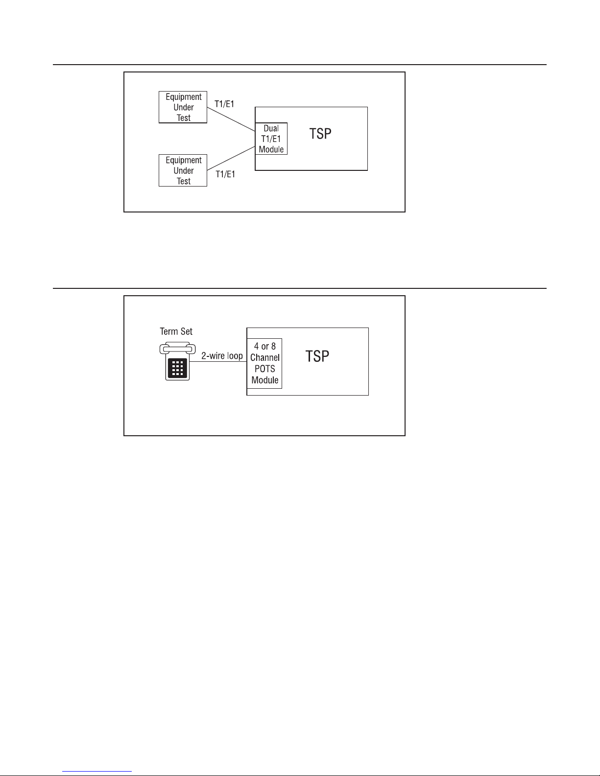
Figure 12 T1/E1, Call Originate and Call Terminate Diagram
With Call Originate mode, the TSP generates calls on the channels of a T1/E1 line to the
equipment under test. With a Dual T1/E1 module, the calls can be generated on both T1/E1’s
simultaneously. Call Terminate mode is where the TSP receives calls from the equipment under
test on the channels of the T1/E1 lines.
Figure 13 Analog Loop Start, Call Originate and Call Terminate
For the POTS channels the TSP generates calls to term set in Call Originate mode. Call
Terminate mode is where the TSP receives calls from the term set.
Bulk Call Generation
Call Originate mode can be used for Bulk Call Generation. Bulk Call Generation are calls that
originate within the TSP, simulating call traffic, terminating at an external device, often with some
audio file playback when the external device answers. This can be used to “stress test” the
equipment under test.
Installation Tests
The TSP can emulate the PSTN and be terminated to a PBX via a T1/E1 circuit or multiple POTS
connections. This allows for testing PBX programming and functionality before live traffic is cut
over to it.
Page 14
Programming the TSP
The software loaded on the PC controls the TSP and its configuration. Multiple projects can be
saved and used for different testing applications and TSP units.
Once all connections have been made and the TSP is powered up, start the TSP program.
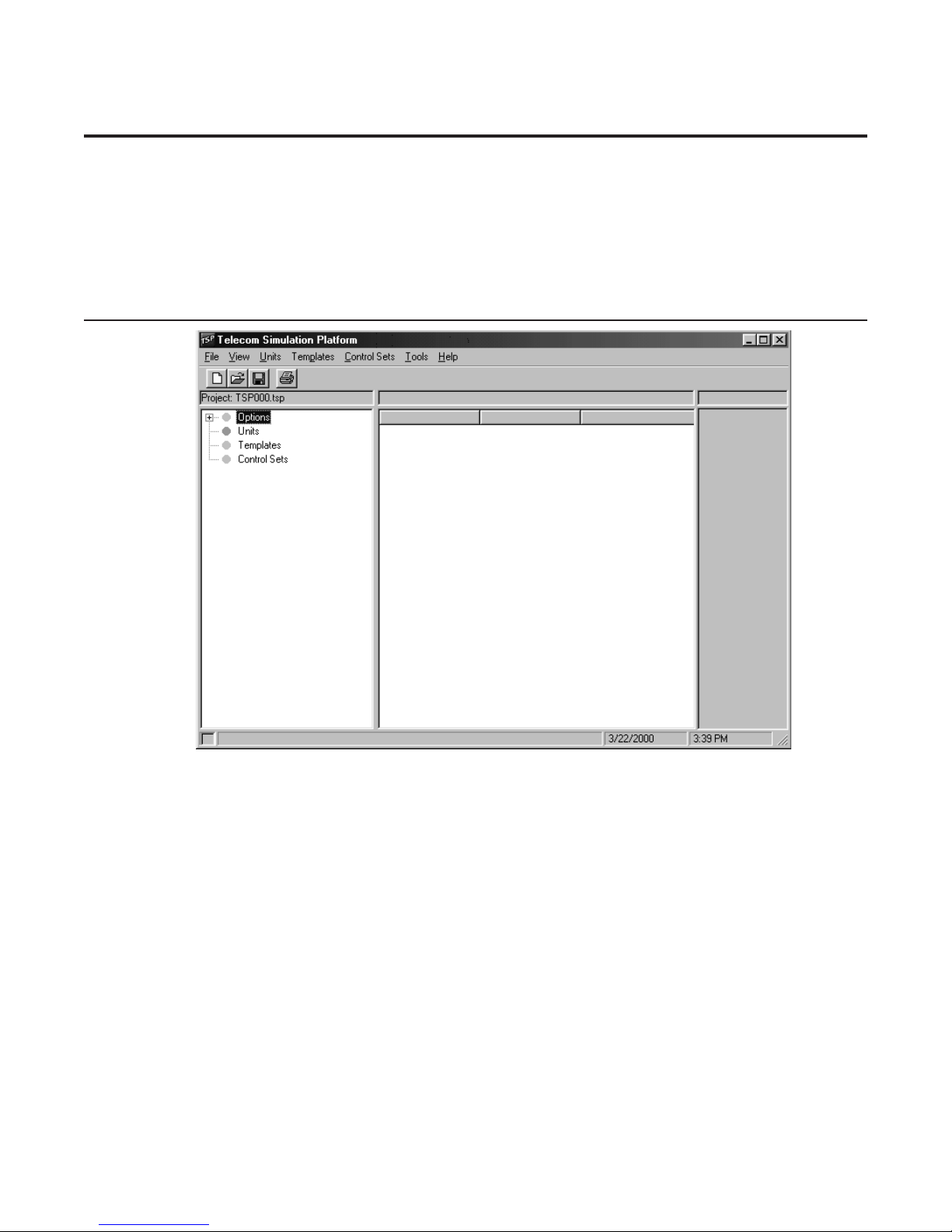
Telecom Simulation Platform (TSP) main screen
Figure 14 TSP Main Screen
The Telecom Simulation Platform screen starts with a default Project file and is ready for
configuring the TSP. Note the following menu options. File creates, saves, or opens TSP
Projects. View is for the Event Log and Options (Options brings up the Alerts settings and
Upgrades information). The Units, Templates and Control Sets menu items are for building and
saving the TSP test configurations. Also under the Units menu is Initializ e to reset the parameters
in the TSP.
The Tools menu item brings up the TSP Diagnostics screen. The Help menu brings up the Help
file.
Tree Display
On the left side is a Tree Display for Options (subset Alerts by clicking on the + sign), Units,
Templates, and Control Sets. A plus sign (+) will appear in front of each of these as simulation
parameters are created. Clicking on the plus sign (+) will expand the display tree and clicking on
the minus sign (-) will do the opposite.
Information Section
To the right side of the Tree Display is the information section. The information section displays
parameters and current states of the item chosen in the Tree Display screen.
40-400-00049, Rev. J Page 15
Telecom Simulation Platform
Control Set Enables
The far right side of the TSP screen is where Control Set Enable buttons will appear once a
Control Set has been created. The buttons are used to activate a Control Set.
During programming and control of the TSP, the box at the bottom left corner of the screen turn
yellow indicating commands are being sent to the TSP. Once complete, the box turns gray.
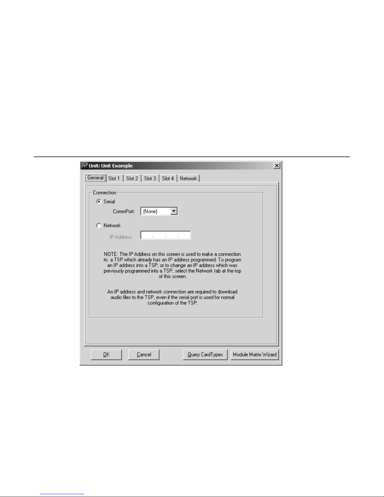
Units
Each TSP must be defined as a “Unit”. The Unit screen is used to define the connection for
communicating to the TSP, the card types installed in the TSP, and specific information for the
Ports and Channels on each card. By clicking on the Units menu item and choosing New, the
prompt “Enter New Unit Name” will appear. For demonstration purposes the name “Unit example”
will be used. The following screen will come up.
Figure 15 Unit Screen
Note the tabs on the Unit screen: General (Connection for Serial or Network control), Slots 1 - 4
(for card types), and Network (for assigning an IP address to the TSP). The Units screen comes
up with the General tab selected. This tab is used to choose the type of connection that will be
used to communicate to the TSP. The Serial connection must be used to start since no IP
address is assigned at this point for the Network control.
Important
Page 16
It will be necessary to obtain an Authorization Code from Teltone Customer Service after the first
Unit is created to enable testing with the TSP. The message: “Unit ‘name’ requires an
Authorization Code to enable its operation. Contact Teltone Corporation.” will appear after you
completed configuring on the Units screen and click OK. Only one Authorization Code is required
to enable the TSP. Programming of the Authorization Code is a one time operation and is stored
Programming the TSP
permanently in the TSP’s memory. Once the Authorization Code is installed, the TSP can be
used with any PC.
Serial Connection
The serial connection is mandatory for initial setup of the TSP. It must be used to establish
control of the TSP and to set up control using the Network Connection by assigning an IP
Address to the unit. Start by choosing the CommPort that will be used to control the TSP. Under
the Serial option, clicking on the arrow will open the drop down menu where you can choose the
connection that will be used.
Important
When using the T1/E1 module in T1-PRI mode, the network connection must be used for
programming and control; the serial connection is not allowed. This allows for enhanced
messaging during PRI operation.
Query Card Types Button
At this point the TSP can be configured for the modules installed. This can be done automatically
by clicking on the Query Card Types button at the bottom of the screen. A screen will pop up
stating “This will set the current units card types to match those actually in the system”. Click OK
to continue. The program has now configured the Slots in the program to reflect the physical
modules in the TSP.
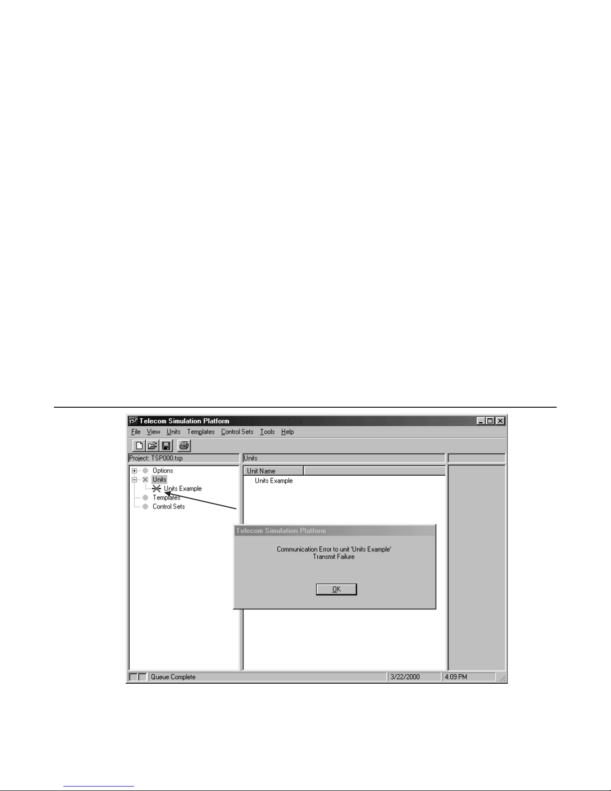
When doing the Query Card Types command without a TSP powered up or connected or if
there’s an IP configuration error, the error message “Communication Error to unit “X” (X being the
unit name) will appear. The second line of the error message will indicate either a “Transmit
Failure” for a serial connection or “Network Connection Failure” for an IP configuration error.
There will also be symbols under Units on the tree display below indicating an error has occurred.
See the symbols in the Icon Legend section.
Figure 16 Example of a communications failure to TSP
Teltone recommends using the Query Card Types command for configuring the TSP. If the TSP
is not connected, manual configuration can be done. To do this, choose the Slot that coincides
40-400-00049, Rev. J Page 17
The red X indicates communication
failure to the TSP

Telecom Simulation Platform
with the position a module is installed by clicking on the tab for that Slot number. The Card Type
is configured by clicking on the arrow and choosing the option.
Module Matrix W izard
It is important during hardware set-up that the modules are installed in the slots of the base unit
per the Module Interface Matrix. The Module Matrix Wizard button on the Units screen (see
Figure 15) can also be used to select the valid module installation configurations. Clicking the
Module Matrix Wizard button displays valid module combinations, as shown in Figure 16A.
Figure 16A Module Matrix Wizard
Important:
When doing a Query Card Types command, if the modules are not installed in the correct slots,
the TSP program will indicate this and refer you to the Module Matrix Wizard for the proper set-up
Before installing or removing a POTS module, connect a telephone set to any port of any POTS
module, power down the unit, and then go off-hook on the telephone set. This allows for voltage
dissipation from the base unit and prevents damage to the unit. An alternative procedure is to
power down the TSP for at least 30 minutes before installing or removing the module.
At this point it is recommended to click OK on the Units screen. You will need to obtain an
Authorization Code to enable the TSP to test.
Also, if you receive a message indicating “newer code is available” click No. You will need to
follow the instructions in the Software Updates section after obtaining the Authorization Code to
successfully download the newer code to the TSP.
Authorization Code
An Authorization Code is necessary to enable the TSP the first time it is used, and also to enable
any purchased software modules (such as TSP-PRI). This code, obtained from Teltone’s
Customer Service, needs to be loaded only once and is stored in the TSP permanently.
Page 18

Programming the TSP
Before contacting Teltone for the Authorization Code, please have the following available:
Hardware ID (see below)
·
Serial Number (on the bottom of the unit)
·
Software Serial Number (on the CD)
·
Your name
·
Your title
·
Your company
·
Your address
·
Your telephone number
·
To read the Hardware ID, click on the View menu of the main window and choose Options. An
Options screen appears. Click on the Upgrades tab. At the Unit Name field, click on the down
arrow and the unit name you created appears. Choose the name, and the Hardware ID appears
underneath. If you have not yet created a Unit Name, see the Units section of this manual.
If you purchased an additional software module, such as TSP-PRI, obtain the Authorization Code
using the serial number from the additional software module CD, which activates both the TSP
and the software module.
To obtain the Authorization Code, contact Teltone’s Customer Service department:
Call: 425-951-3388 or
Fax: 425-487-2288 or
Email: info@teltone.com.
Once you have the Authorization Code, enter it on the screen where you obtained the Hardware
ID and click Install. The TSP will be enabled to run simulations.
Software Updates
If the TSP software version on the PC is newer than the code on the TSP unit, a “newer code is
available” message will display.
The message box text is as follows:
“Newer code is available for unit ‘Units Example’. Do you wish to download to your TSP now?
Note: You must have a network connection to the TSP to download.”
The TSP must have an Ethernet connection and an IP address assigned for the download to be
successful. Answer No, if this has not been done and follow the instructions in the next section,
Network Connection. Once the TSP is assigned an IP, the download can be done by clicking OK
on the Units screen or initializing the Unit. This can be done with either the Serial or Network
Connection chosen on the General tab of the Units screen.
If it’s indicated that the code on the TSP is newer than that on the PC, download the latest
version of the software from the Teltone web site at www.teltone.com.
Network Connection
The network connection can be used for programming and control of the TSP, WAV file
downloads and software updates utilizing the Ethernet port on the TSP. It must be used when the
T1/E1 module is programmed for T1-PRI mode to allow for enhanced messaging. The initial
set-up of the IP address for the network connection must be done from the Network tab on the
Units screen via the serial connection. The Network tab is used to assign a new IP or to change
an existing IP.
40-400-00049, Rev. J Page 19

Telecom Simulation Platform
The IP Address field on the General tab for the Units screen displays the IP of the TSP that is
currently being communicated with and is used to connect to other TSP’s already assigned an IP
address and connected to the network. If the serial connection is used for control of the TSP, the
Ethernet connection is still required if using audio files or to download software updates.
To set-up, ensure you have connected the TSP ethernet port to the LAN with a straight through
cable. For connecting directly to the PC with the crossover cable provided, use a valid IP format
that is in the same subnet and uses a valid subnet mask. If connecting to a LAN, see the network
administrator to assign a static IP for the TSP. Go to the Units menu, click on the unit name and
select the Network tab on the Units screen to input the IP address. Click OK on the Units screen.
Network Control
The Network connection can be used for controlling the TSP. This is done by going to the Units
menu, and clicking on the name of the unit at the bottom of the drop-down window. On the Units
screen, the IP address programmed into the Unit will be displayed. Click the radio button for the
Network connection and click OK. The TSP will be controlled via the Ethernet connection to the
TSP at this point.
If the IP address is not displayed, follow the instructions in the previous Network Connection
section to program the TSP with one.
Network control can only be done by PCs on the same subnet as the TSP.
Connecting to an Existing TSP
You can connect to any other TSP that has been assigned a valid IP address and is on the
network. This is done by creating a new Unit, choosing the Network radio button, inputting the
existing IP address of the unit you wish to connect in the IP Address field on the General tab,
clicking on Query Card Types and clicking OK. The Query Card Types action is done to match
the card types in the TSP to your project. Otherwise an error message will occur advising card
types do not match.
If you want to connect to a TSP that you previously have connected to, the program will
remember the name and the IP address of all the TSP’s that PC has connected to. To do this, go
to Units and select New. On the new Unit window, click on the arrow at the right of the entry field.
Select the name of the unit you wish to connect. This will populate the last known IP address for
that unit name. The Query Card Types command will still need to be done.
Override
If a TSP is accessed when it is in use, an Override message will appear. The machine name of
the party using it will be given and the option to override the connection. If the override is
implemented, the machine that was previously connected to the TSP will receive a
Communication Error message advising of the Network Connection Override and the machine
name of the party that took control. All Override actions are recorded on the Event Log found on
the View menu (see Event Log section of TSP manual for more details).
This feature is necessary to regain control of the TSP in the case of a broken connection to the
network by the PC controlling it. This also makes it convenient to control the TSP from different
locations.
To take control back when a connection is overridden, go to the Units menu, choose Initializ e and
the name of the Unit.
Changing an IP Address
To change an IP Address of a TSP already programmed with one, go to the Units menu and
choose the name given the TSP. This will bring up the Units screen. Choose the Network tab,
input the new IP address and click OK. The TSP will now have the new IP address and the PC
program will be communicating using the new IP address.
Page 20
Programming the TSP
If a Project is opened that has the previous IP address of a TSP unit, the program will advise of
the new IP address and ask if you want to change to the new IP address. This only occurs on the
PC that was controlling the TSP when the IP was changed.
Slot Tabs
Once the Card Types and the connection for programming and control of the TSP are defined,
there are different options available to configure depending on the Card Type. Choose the Slot
Tab that has a Dual T1/E1 or Single T1/E1 card installed. If a T1/E1 card is not being used, skip
to the 4 and 8 Channel POTS Card Type screens.
Single T1/E1 and Dual T1/E1 Card Types
For T1/E1 modules, the Card Mode field will be displayed to the right of the Card Type field. T1
(default) will be displayed. Clicking the arrow will give the options E1 and T1-PRI.
Note:
T1-PRI is available when the TSP-PRI Software module is purchased. Refer to the TSP-PRI
section for configuring in this mode.
When using two Single T1/E1 modules, both modules have to be configured for the same Card
Mode and PCM encoding /companding. The Slot 3 selection for Card Mode and mu-law or a-law
will be grayed out with the selections on Slot 2.
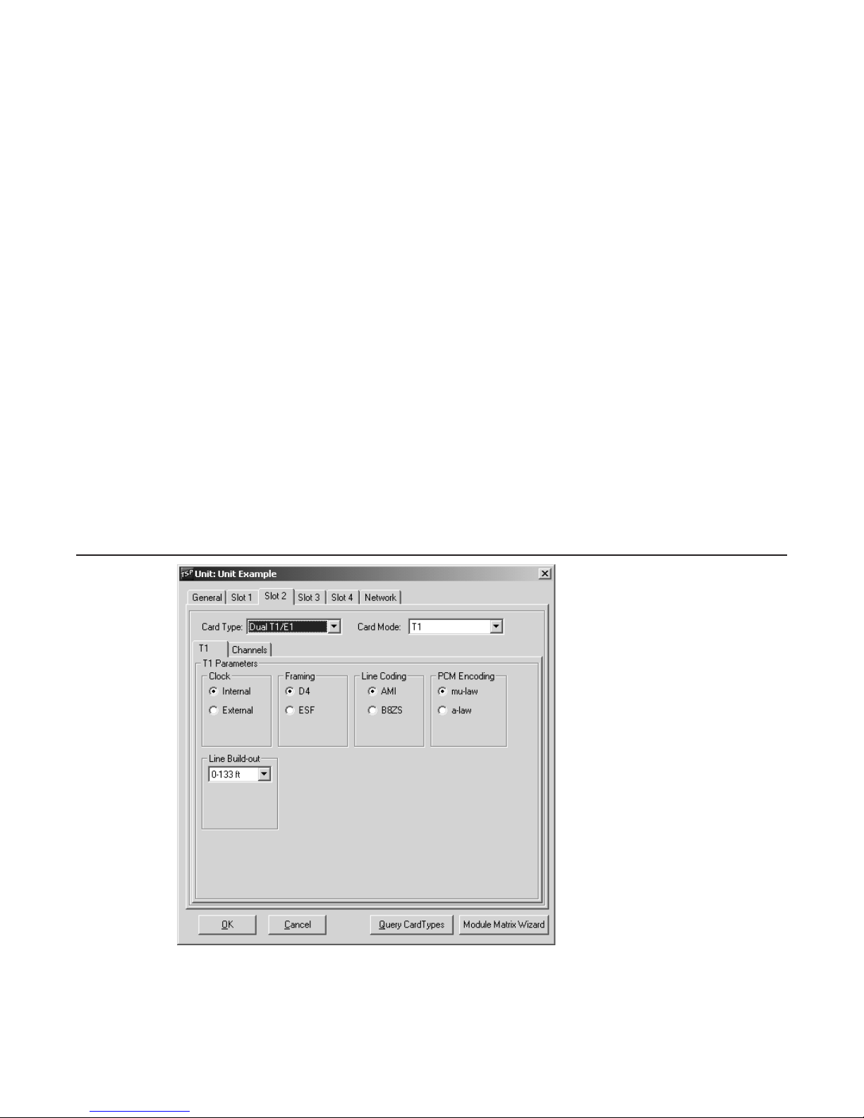
T1 Card Mode
Figure 17 shows the parameters on the T1 tab in the T1 card mode. The T1 parameters include,
Clock, Framing, Line Coding and PCM Encoding options. They are configured on this screen by
clicking on the corresponding radio button. The Line Build-out defaults to 0-133 ft (0 dB level) but
can be changed for different distances or dB loss expected on the line.
Figure 17 T1 Parameters Screen
Clock
The Clock needs to be set to where one end is providing timing (normally the PSTN) while the
other end is deriving clock from it (usually the CPE). The Internal clock setting is used when the
TSP acts as the PSTN and provides the clocking to the equipment under test. External Clock is
40-400-00049, Rev. J Page 21

Telecom Simulation Platform
used when the TSP acts as the CPE and clocks from the equipment under test (i.e., if the TSP is
set for Internal clock, the equipment under test should be set for External clock, and vice versa).
Note:
Important
If using only one port on a Dual T1/E1 that is configured for External Clock, port 2 must be used
and will derive its clock from the equipment under test. If using both ports, the device connected
to Port 1 must use the same clocking reference as the device connected to port 2.
Framing
With Framing, both ends need to match, otherwise synchronization will not be achieved. D4 is
considered a more common format while ESF (extended superframe) provides for overhead
features such as a data link and CRC-6 for detection of errors without interrupting the signal. The
TSP does not report data link information for CRC-6 errors.
Line Coding
For Line Coding, AMI suffices if no DDS data exists on any of the T1 channels. B8ZS is used
when DDS data channels are present to compensate for when an all Zeros state exists (when
equipment is off). This can lead to lost of synchronization on the T1 data stream due to too many
successive zeros.
PCM Encoding
For PCM Encoding, the choices are mu-law and a-law. For T1, mu-law is the default. This is the
PCM encoding and companding standard used in North America and Japan. For E1, a-law is the
default and is the PCM encoding and companding standard used in Europe.
On Dual T1/E1, both channels are configured for the same clock, framing (for T1), signaling (for
E1), and line coding. Ensure the T1/E1 parameters are consistent with the configuration of the
equipment under test. This information can be found in the equipment manual or by contacting
the vendor.
Page 22
 Loading...