

Page 1

Telephone Line Emulator
TLE-A
User’s Manual
40-400-00020, Rev. M
Page 2

Note
This manual covers Model TLE-A-01 and software modules TLE-ADV (Advanced Emulation),
TLE-INTL (International), and TLE-ICID (International Caller ID).
Copyright Notice
Copyright © 1997 - 2003 Teltone Corporation
All Rights Reserved
Trademarks
Teltone is a registered trademark of Teltone Corporation.
Windows is a registered trademark of Microsoft Corporation.
Other company and product names may be trademarks or
registered trademarks of their respective owners.
Teltone Corporation
Bothell, Washington 98021 USA
Customer Service: 425-951-3388
Technical Support: 425-951-3390
Fax: 425-487-2288
Email: info@teltone.com
Website: www.teltone.com
ii 40-400-00020, Rev. M
Page 3

Contents
Overview ...................................................................................................................................................................1
Standard Unit Features (TLE-BASE) ...............................................................................................................1
Options ............................................................................................................................................................1
International Software Module (TLE-INTL).................................................................................................1
International Caller ID Software Module (TLE-ICID) ..................................................................................2
Advanced Emulation Software Module (TLE-ADV) ....................................................................................2
Automated Test Software Module (TLE-TEST)..........................................................................................2
TLE Front and Rear Panels .............................................................................................................................3
Getting Started ..........................................................................................................................................................4
Check your TLE Package ................................................................................................................................4
Product Registration ........................................................................................................................................4
Setting up the TLE.....................................................................................................................................................5
Power up the TLE ............................................................................................................................................ 5
Installing the TLE Configuration Software........................................................................................................5
TLE Operation .................................................................................................................................................6
Basic Calling Operation ...................................................................................................................................9
Configuring the TLE ................................................................................................................................................10
Main TLE Screen ........................................................................................................................................... 11
Copy Configurations ......................................................................................................................................12
Operational Screens................................................................................................................................................ 14
Audio Line Monitor.........................................................................................................................................14
Busy Tone......................................................................................................................................................15
Call Waiting....................................................................................................................................................16
Caller ID - Visual Message Waiting ...............................................................................................................18
Advanced Screen Telephony.........................................................................................................................22
DC Signaling..................................................................................................................................................22
Dial Tone .......................................................................................................................................................24
Loop Parameters ...........................................................................................................................................25
Miscellaneous ................................................................................................................................................26
Phone Numbers.............................................................................................................................................28
Port Configuration..........................................................................................................................................30
Reorder..........................................................................................................................................................31
Ringing...........................................................................................................................................................32
Special Information Tones/Number Unobtainable Tone ................................................................................33
Voice Messages ............................................................................................................................................34
References ..............................................................................................................................................................35
Advanced Emulation Software Module (TLE-ADV) .................................................................................................36
Impairments ................................................................................................................................................... 36
Metering Tones..............................................................................................................................................37
Signal Level Measurement ............................................................................................................................38
International Software Module (TLE-INTL)..............................................................................................................39
Rotary Dialing ................................................................................................................................................39
References ....................................................................................................................................................40
Reset to Defaults ...........................................................................................................................................40
Country Screen.............................................................................................................................................. 41
Importing Additional Countries.......................................................................................................................41
Call Waiting....................................................................................................................................................42
Metering Tones..............................................................................................................................................43
Special Information Tones/Number Unobtainable Tone ................................................................................43
Loop Parameters (TLE-INTL) ........................................................................................................................45
Country Default Settings................................................................................................................................45
Australia Defaults .....................................................................................................................................46
Austria Defaults........................................................................................................................................ 47
Belgium Defaults......................................................................................................................................48
Brazil Defaults ..........................................................................................................................................49
China Defaults..........................................................................................................................................50
Denmark Defaults ....................................................................................................................................51
Finland Defaults .......................................................................................................................................52
France Defaults........................................................................................................................................ 53
40-400-00020, Rev. M iii
Page 4

Contents
(Continued)
Germany Defaults ....................................................................................................................................54
Greece Defaults .......................................................................................................................................55
India Defaults ........................................................................................................................................... 56
Ireland Defaults ........................................................................................................................................57
Italy Defaults ............................................................................................................................................58
Japan Defaults .........................................................................................................................................59
Korea Defaults .........................................................................................................................................60
Netherlands Defaults................................................................................................................................61
Norway Defaults.......................................................................................................................................62
Singapore Defaults...................................................................................................................................63
Spain Defaults.......................................................................................................................................... 64
Sweden Defaults......................................................................................................................................65
Switzerland Defaults ................................................................................................................................66
UK Defaults..............................................................................................................................................67
US/Canada defaults ................................................................................................................................. 68
International Caller ID Software Module (TLE-ICID)................................................................................................69
Introduction .................................................................................................................................................... 69
Overview - TLE-ICID...................................................................................................................................... 69
Details of Operation .......................................................................................................................................70
Caller ID Timing Parameters..........................................................................................................................73
Programming .................................................................................................................................................74
Caller ID and Call Waiting Modes ............................................................................................................74
Caller ID and CIDCW Components and Sequence..................................................................................76
Caller ID Miscellaneous Parameters ........................................................................................................ 80
Phone Number Prefix and Group Selections ...........................................................................................81
Caller ID and Call Waiting Tones .............................................................................................................83
DTMF CID Parameters ............................................................................................................................84
Timings ....................................................................................................................................................86
Australia Defaults...........................................................................................................................................90
France Defaults .............................................................................................................................................92
Germany Defaults..........................................................................................................................................94
Netherlands Defaults .....................................................................................................................................96
Singapore Defaults ........................................................................................................................................97
Sweden Defaults............................................................................................................................................98
UK Defaults....................................................................................................................................................99
US/Canada Defaults ....................................................................................................................................101
References ..................................................................................................................................................102
Automated Test Software Module (TLE-TEST).....................................................................................................104
Automated Test Screen ...............................................................................................................................104
Revision History ....................................................................................................................................................106
Troubleshooting..................................................................................................................................................... 110
Errors on Power-up...................................................................................................................................... 110
Informational and Error Messages...............................................................................................................111
Telephone Wiring Variants........................................................................................................................... 114
Warranty and Service............................................................................................................................................116
Warranty Information ...................................................................................................................................116
Return Procedures....................................................................................................................................... 116
Technical Assistance ...................................................................................................................................116
Maintenance ................................................................................................................................................116
Ordering Information .............................................................................................................................................117
Specifications ........................................................................................................................................................118
Glossary ................................................................................................................................................................ 123
Index .....................................................................................................................................................................128
iv 40-400-00020, Rev. M
Page 5
IMPORTANT SAFETY INSTRUCTIONS
When using this product, basic safety precautions, including the following, should always be followed to reduce the risk of
fire, electric shock, and injury to persons.
1. Read and understand all instructions.
2. Follow all warnings and instructions marked on the product.
3. The product should be operated only from the type of power source indicated on the marking label. If you are not sure
of the type of power supply, consult your dealer or local power company. The product is designed for indoor use only.
4. To reduce the risk of electric shock, do not disassemble the product, but take it to qualified service personnel when
service or repair work is required. Opening or removing covers may expose you to dangerous voltages or other risks.
Incorrect reassembly can cause electric shock when the appliance is subsequently used.
5. If the product does not operate normally by following the operating instructions, or if the product has been dropped or
the cabinet has been damaged, or if the product exhibits a distinct change in performance, refer servicing to qualified
service personnel.
6. If the product is used in a manner other than specified in this manual, the protection provided by the product may be
impaired.
7. For the purpose of removing power from the product, the power input connector is the main power disconnect point.
Pull the power cord away from the connector to ensure power disconnect.
8. Adequate air flow must be maintained in order for the product to operate correctly. Do not wrap the product in
blankets, paper, or other material that may impede ventilation.
40-400-00020, Rev. M v
Page 6

REGULATORY COMPLIANCE
FCC Part 15 Class A Notice: This equipment has been tested and found to comply with the limits
for a Class A digital device, pursuant to part 15 of the FCC Rules. These limits are designed to
provide reasonable protection against harmful interference when the equipment is operated in a
commercial environment. This equipment generates, uses, and can radiate radio frequency energy
and, if not installed and used in accordance with the instruction manual, may cause harmful
interference to radio communications. Operation of this equipment in a residential area is likely to
cause harmful interference in which case the user will be required to correct the interference at his
own expense.
The Installation Category (OVERVOLTAGE CATEGORY) for this device is II and it is designed to
be safe under POLLUTION DEGREE 2, per IEC 1010-1: 1990 specifications.
vi 40-400-00020, Rev. M
Page 7

Telephone Line Emulator User’s Manual
Overview
The Teltone Telephone Line Emulator (TLE) is a user-configurable four-port analog
telephone emulator, enabling simulation of many public switched telephone network
(PSTN) conditions. The TLE is designed to work between 100 VAC and 240 VAC,
enabling the TLE to be used worldwide. There is an International Software Module, an
Advanced Simulation Software Module, an Automated Test Software Module, and an
International Caller ID Software Module available. These options are designed to work
individually with the basic TLE, or they can be mixed and matched depending on the
user’s requirements.
Standard Unit Features (TLE-BASE)
• Two user-selectable configuration settings
• 2 x 2 port or 4 port operation
• Vacuum Florescent Display for telephone port status information and other messages
• 600 or 900 ohm programmable input impedance
• Programmable ring frequency, ringback tones, voltage, and cadence
• Programmable loop current
• Programmable DC signaling (on/off-hook, flash, disconnect and line reversal)
• Programmable attenuation
• Three programmable numbers for each line
• Call Waiting, Visual Message Waiting, Stuttered Dial Tone
• Caller ID, SCWID (Caller ID in Call Waiting), and DSCWID (SCWID with Disposition
• Programmable dial tone, busy tone, reorder tone, and special information tones (SIT)
• Five dial-up test tones plus one programmable test tone
• Calling Party Control, network delays, dialing mode, and other miscellaneous settings.
• Audio Messaging, Import WAV files from the PC, Multiple Message Playback
• 100 to 240 VAC power supply
• CE Mark Compliance
• Programming via Windows
• 3.5 mm mono audio jack for monitoring audio
-based software using a serial port
Options
International Software Module (TLE-INTL)
Basic unit features plus:
• 16 stored configuration settings which include:
• 11 predefined Country specific settings
• 5 preset North America settings
• 11 additional Country settings included
• Programmable 12 or 16 kHz metering tones
• Ability to call from one country configuration to another
• Complex impedances for Australia, Ireland, Germany, UK, and Switzerland
40-400-00020, Rev. M 1
Page 8

Telephone Line Emulator User’s Manual
International Caller ID Software Module (TLE-ICID)
This module is an upgrade to TLE-INTL Software Module.
• Supports Multiple Caller ID formats
• Bellcore
• Bellcore Plus
• ETSI FSK
• ETSI DTMF
• Default Country Caller ID Configurations for:
• Australia (Bellcore Plus)
• France (ETSI FSK)
• Germany (ETSI FSK)
• Netherlands (ETSI DTMF)
• Singapore (Bellcore Plus)
• Sweden (ETSI DTMF)
• United Kingdom (ETSI FSK)
• USA/Canada (Bellcore)
• Many programmable parameters
Advanced Emulation Software Module (TLE-ADV)
Basic unit features plus:
• 16 stored configuration settings
• Echo emulation
• White noise emulation
• Satellite delay emulation
• Signal level measurement
• Enable Caller ID after every ring
• Enable/Disable DTMF detection (for pulse dial only applications)
• Metering tones
Automated Test Software Module (TLE-TEST)
Basic unit features plus:
• Control of TLE through serial port using API commands
• Ability to write customizable scripts for repetitive testing
• API definitions in both Visual Basic and C++ formats
• Programmable frequency sweep tone
• Status messages on front panel and through serial port
• Includes access to International and Advanced Emulation features
• Designed specifically for product development and production test applications
• International Caller ID features available with installation of TLE-INTL and TLE-ICID
software modules
40-400-00020, Rev. M 2
Page 9
Telephone Line Emulator User’s Manual
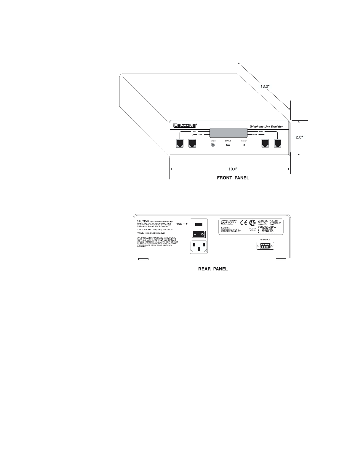
TLE Front and Rear Panels
Figure 1. Telephone Line Emulator Front and Rear Panels
40-400-00020, Rev. M
3
Page 10

Telephone Line Emulator User’s Manual
Getting Started
Check your TLE Package
Your basic package should include the following items:
• TLE-A-01 unit
• 110 VAC power cord for use in North America
• 9-pin male to 9-pin female RS-232 cable
• 9-pin male to 25-pin female adapter
• CD-ROM containing configuration software and User Manuals
• Product Registration Card
The following items may be included as options:
• International Software Module (TLE-INTL)
• International Caller ID Software Module (TLE-ICID) - Requires purchase of the
International Software Module.
• Advanced Emulation Software Module (TLE-ADV)
• Automated Test Software Module (TLE-TEST)
• 7-foot modular telephone cable
• 25-foot modular telephone cable
• 9-pin male to 9-pin female RS-232 cable (1 supplied with each TLE unit)
• 9-pin male to 25-pin female adapter (1 supplied with each TLE unit)
• 7.5 foot 110 VAC power cord (1 supplied with each TLE unit)
If any of the items you ordered are missing or damaged, contact Teltone’s Customer
Service at 425-951-3388.
Product Registration
Please complete the Product Registration card and mail it to Teltone Corporation. This will
place you on the mailing list for information regarding feature enhancements and product
upgrade information.
40-400-00020, Rev. M 4
Page 11

Telephone Line Emulator User’s Manual
Setting up the TLE
Power up the TLE
The TLE uses a universal power supply that operates from 100-240 VAC, 50/60 Hz.
Connect AC power to the TLE, then turn the rear panel power switch to the ON position.
Grounding is assured by using the appropriate (approved) power cord.
The green Status LED on the front panel will indicate the state of the system. The LED
should blink between mid-to-full brightness. If the LED fails to light, disconnect power
immediately and contact Teltone Technical Support at 425-951-3390.
Adequate air flow must be maintained in order for the unit to operate correctly. Do not
wrap the unit in blankets, paper, or other material that may impede ventilation.
Installing the TLE Configuration Software
The TLE Serial Port uses a standard RS-232 DCE interface. Using the cable provided,
connect the TLE to a personal computer running a Windows-based operating system.
(Optional with PC-software V2.00 or greater.)
Windows 95 or Later Versions
1. Insert the CD-Rom into the drive.
If the installation automatically starts, skip to step 4.
2. On the TaskBar, left click START, then RUN.
3. Type in your drive designator, followed by Setup.exe
example: r:\setup.exe
4. Follow the instructions on the screen to complete the installation.
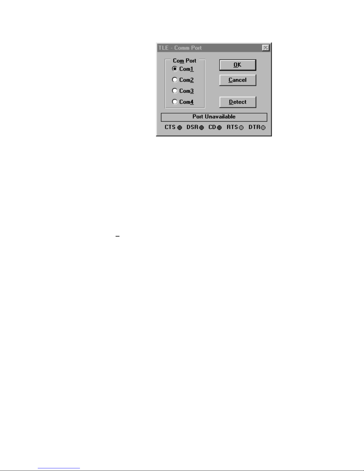
5. Confirm that the correct communications port is configured. PC-Software V2.00 and
greater will automatically display the TLE-Comm Port selection screen if the TLE is not
connected or uses a port other that Comm1. Select the appropriate port and then
etect. The TLE software will test to see if your TLE is connected. The control leads
D
status are shown at the bottom of the window. If the TLE is connected with the proper
cable; all should be green. If not; CTS, DSR, and CD are normally red. Select Cancel
if your TLE is not connected at this time. Select OK to complete the CommPort
selection.
40-400-00020, Rev. M
5
Page 12
Telephone Line Emulator User’s Manual
Windows 3.1 and Windows 3.11 (Windows for Workgroups)
1. Insert the CD-Rom into the drive.
2. Using the Windows Program Manager, Select File, Run.
3. Type in your drive designator, followed by Setup.exe
example: r:\setup.exe
4. Follow the instructions on the screen to complete the installation.
5. Confirm that the correct communications port is configured. PC-Software V2.00 and
greater will automatically display the TLE-Comm Port selection screen if the TLE is not
connected or uses a port other that Comm1. Select the appropriate port and then
etect. The TLE software will test to see if your TLE is connected. The control leads
D
status are shown at the bottom of the window. If the TLE is connected with the proper
cable; all should be green. If not; CTS, DSR, and CD are normally red. Select Cancel
if your TLE is not connected at this time. Select OK to complete the CommPort
selection.
Figure 2. TLE - Comm Port Screen
TLE Operation
40-400-00020, Rev. M 6
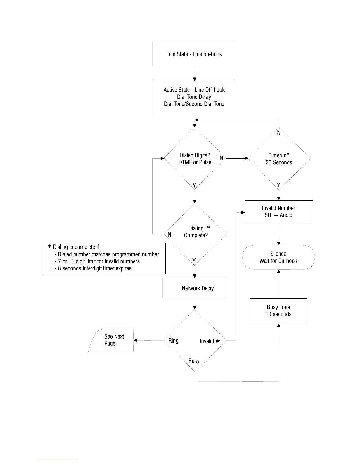
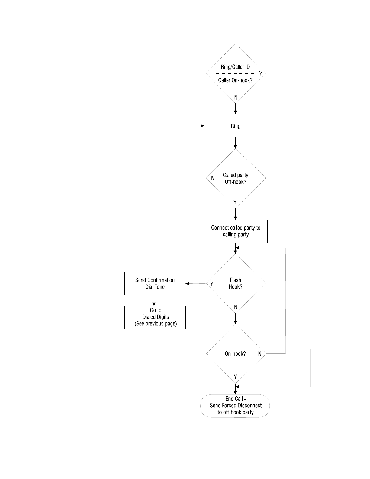
The following call process flowchart will help to explain the basics of call setup and
completion. More detailed explanations are included after the flowchart.
Page 13
Telephone Line Emulator User’s Manual
40-400-00020, Rev. M
Figure 3. TLE Call Processing Flowchart (Part 1)
7
Page 14
Telephone Line Emulator User’s Manual
40-400-00020, Rev. M 8
Figure 4. TLE Call Processing Flowchart (Part 2)
Page 15

Telephone Line Emulator User’s Manual
Basic Calling Operation
The Teltone TLE provides dial tone (Normal – default), or Ringdown (Hotline), or a quiet
battery feed (Silent), when a device goes off-hook and draws sufficient loop current. When
dialing is detected, DTMF or Pulse (aka Rotary dialing), dial tone stops. If an invalid
sequence is dialed, the TLE will issue an Invalid Number Response of SIT + Audio
(default), SIT repeating, Busy, Reorder, Ringback, Silence, or Audio. If a valid number is
dialed, a Hunt Mode of Ring All (default), Ring 1st match, Ring 1st available, or Ring next,
is invoked. Caller ID information is sent to the Called Party, along with Ringing, and
Ringback tone is sent to the Calling Party. When the called line answers, a connection is
established between the two parties.
During an existing call, another party may go off-hook and dial a number that matches one
of the connected parties. If so, then a SAS (Call Waiting tone) + CAS (Caller ID tone) is
issued to the called party. If the called party has a Caller ID box or phone that supports
SCWID (aka Caller ID in Call Waiting), then the Caller ID information will be issued by the
TLE. If the called party does not answer the waiting call, a repeat of the Call Waiting tone
occurs ten seconds after the first. During an existing call, either party may wish to
Transfer/Conference another party. To accomplish this, the originating party must
generate a hook flash, after which the TLE will return a Confirmation Dial Tone, and the
originating party will dial the number of a third party. After connecting to the third party, all
three are brought together with another hook flash. Conference operation is dependent
upon the setting of the Conference Type in the Miscellaneous Screen.
The end of a call uses Calling Party Control. If the Called Party hangs up, the connection
may be re-established if they go off-hook before the Forced Disconnect Timer expires. If
the Calling Party goes on-hook, or if the Forced Disconnect Timer expires, then a Forced
Disconnect signal, a break in the loop current, is sent to the remaining party if they are offhook. After a Forced Disconnect signal is sent, and the party remains off-hook, then
Disconnect Treatment is invoked. The options include Dial Tone (default), Busy, Reorder,
Silence, or an Audio message.
The TLE supports a few special dialing sequences. These include:
Special Caller ID dial ∗67 + telephone number to send PRIVATE
dial ∗87 + telephone number to send OUT OF AREA
dial ∗88 + telephone number to send Checksum error
Speed Dialing dial 1#, 2#, 3#, or 4# to access lines 1,2,3, or 4 respectively
Visual Message Waiting dial ∗50 + telephone number to turn VMW ON
dial ∗51 + telephone number to turn VMW OFF
DTMF Programming dial ∗∗99##
Set Active Configuration dial ∗xx#, where xx is the configuration #
Version Query dial ∗99#, view display for versions
Special Telephone Numbers (programmable) include:
Audio Access Message dial 411
Dial Tone (continuous) 83781 (TEST1)
Busy (continuous) 83782 (TEST2)
Reorder (continuous) 83783 (TEST3)
Ringback (continuous) 83784 (TEST4)
Special Test Tone (continuous) 83785 (TEST5)
Stuttered Dial Tone (continuous) 83786 (TEST6)
40-400-00020, Rev. M
9
Page 16

Telephone Line Emulator User’s Manual
Configuring the TLE
Using the Configuration Software, different configurations can be saved to download to
the TLE. A configuration contains all the programmable parameters of the TLE. The
standard TLE (TLE-BASE) unit can have 2 different configurations, while the add-on
software modules can have up to 16 different configurations.
The Active Configuration is the configuration that is being used by the TLE. Any
configuration may be selected as the Active Configuration using the Configuration
Software, or an ASCII command string via the serial port, or a DTMF dialing sequence
from a device connected to a port. See below for more information.
A Configuration Set is a file name given to reference the configurations saved. Only one
Configuration Set can be downloaded to the TLE, although multiple Configuration Sets
can be saved on the PC.
Editing a configuration may be done off-line, or while connected to the TLE. While
connected to the TLE, changes made are updated in the TLE by either selecting the
APPLY or OK button on each screen. Using the APPLY button will implement the
changes but keep the current screen to allow for any additional changes. Using the OK
button will implement the changes, exit the screen and return to the Main screen. If the
update is to the Active Configuration, every update will cause the display of the TLE to
show “Initializing Configuration” and then “Active Configuration” and then the configuration
number. The TLE must be in the idle state (all lines on-hook) for the update to occur. If
the update is to a configuration that is not currently active, the TLE display will not change.
When the TLE_PC software is run, it will read the Unit Name and the Active
Configuration of the TLE and display them on the Main screen of the software. If there is
no TLE connected, the title bar will read TLE_PC - No Unit Connected. If there is a TLE
connected and the Configuration of the TLE does not match the default configurations in
the software, a screen will appear asking whether you want to query the TLE for its
configuration settings. In addition, any time the TLE is initially connected, the software
will automatically query the unit for firmware version information. If the software has an
updated version, it will ask you if you want to download the new code.
Reset
On the front panel of the TLE there is a recessed button called Reset. Pressing this
button for greater than 1 second once will display a prompt asking. “Reset all configs?
Press Reset = yes”. Pressing Reset a second time for greater than 1 second will reset the
TLE configuration memory to the factory default settings with Configuration 1 active.
When the front panel Reset button is pressed, the unit will be reset to the US/Canada
defaults for all configurations. The user must perform Defaults and Send All from the PC
configuration software to reload the defaults for each individual country configuration.
Selecting Active Configuration using DTMF
All other ports must be on-hook and the dialing sequence is as follow: go off-hook, dial
∗∗99## to enter Programming Mode, then dial ∗xx#, where xx is the configuration
number. For example, to select configuration 02, dial ∗02# and the TLE will respond with
40-400-00020, Rev. M 10
Page 17
Telephone Line Emulator User’s Manual
a three beep confirmation tone (if enabled), and the display will show the new
configuration following an initialization sequence. If an error in the entry occurs, the TLE
will respond with a single beep error response.
Selecting Active Configuration using the serial port
The Active Configuration may be selected via the serial port with PC_TLE software 2.00 or
greater. This is accomplished by setting up the serial port at 9600 baud, 8 data bits, 1
stop bit, no parity, hardware flow control, and sending an ASCII string to change the
Active Configuration. The format of the message to the TLE is either:
:XX<cr> or,
:XX,YY<cr>
The TLE will respond with !OK if the command is accepted or !ERR if it is rejected.
:XX will set the active configuration from 01 to 16 for all 4 ports and :XX,YY will set the
active configuration XX for ports 1 and 3 and YY for ports 2 and 4.
Note: Local echo of command characters is not provided by the TLE.
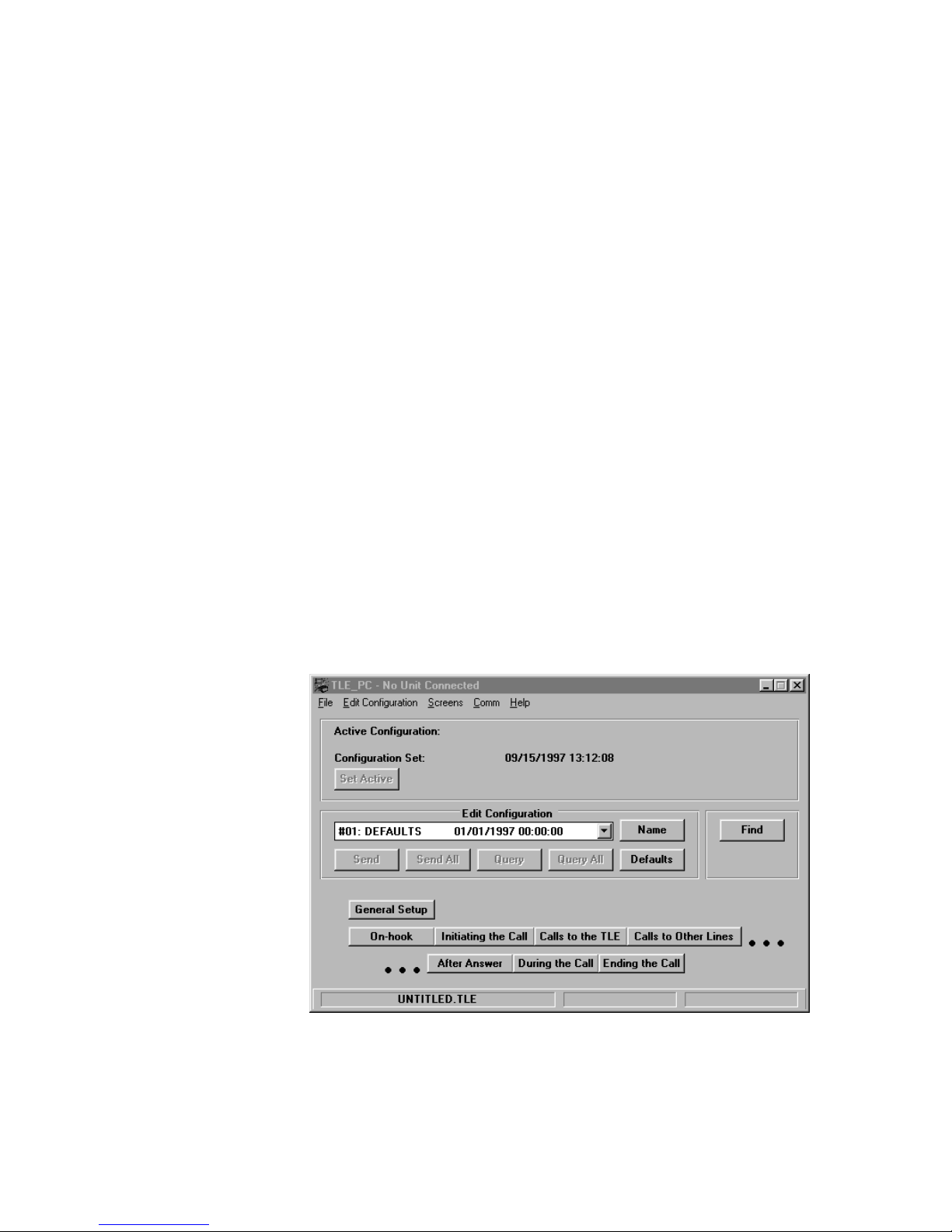
Main TLE Screen
The top section of the main TLE screen displays the Active Configuration Number,
Name, and Date/Time it was created, if a TLE is connected. This field will be blank if no
TLE is connected. It also shows the current Configuration Set Name and the Date/Time
it was created. The Set Active button allows the user to choose the Active Configuration
in the TLE.
The middle section of the screen displays the Configuration being edited. The Name
button allows the user to change the name of each configuration. The Send button sends
the current configuration being edited to the TLE. The Send All button sends all of the
40-400-00020, Rev. M
Figure 5. Main TLE Screen (No TLE Connected)
11
Page 18
Telephone Line Emulator User’s Manual
configurations in the Configuration Set to the TLE. The Query button will query the
settings for the current configuration in the TLE. The Query All button will query all of the
stored configurations in the TLE. The Defaults button will reset any Configuration under
edit to the factory default settings.
The bottom section displays buttons that conform to the natural order of call placement
and pressing any of these buttons will bring up windows with information regarding the
operation of the TLE. Another method to use when changing the operation of the TLE is
to use the S
alphabetical order. A Find button is also supplied to help with locating the parameter to
be changed.
The bottom line of the Main screen will report three items:
1) The name of the saved file under edit.
2) If the Configuration Set under edit matches what is stored in the TLE, Set=TLE will be
displayed. If the Configuration Set does not match, Set<>TLE will be displayed.
3) If the Configuration being edited matches the configuration stored in the TLE,
Configuration=TLE will be displayed. If not, then Configuration<>TLE will be displayed.
The S
These are broken into individual screens labeled as Audio, Busy, Call Waiting, Caller
ID, DC Signaling, Dial Tone, Loop Parameters, Miscellaneous, Phone Numbers, Port
Configuration, Reorder, Ringing, Special Information Tones, and Voice Messages.
Other screens that are active if the TLE-INTL, TLE-ADV, or TLE-TEST software modules
are purchased include Country, Metering Tones, Impairments, Signal Level
Measurement, and Automated Test. The TLE-ICID Software Module combines Call
Waiting and Caller ID into a single screen called Caller ID/Call Waiting.
creens menu on the menu bar. All of the screens are displayed in
creens menu is used to change the settings of the operational features of the TLE.
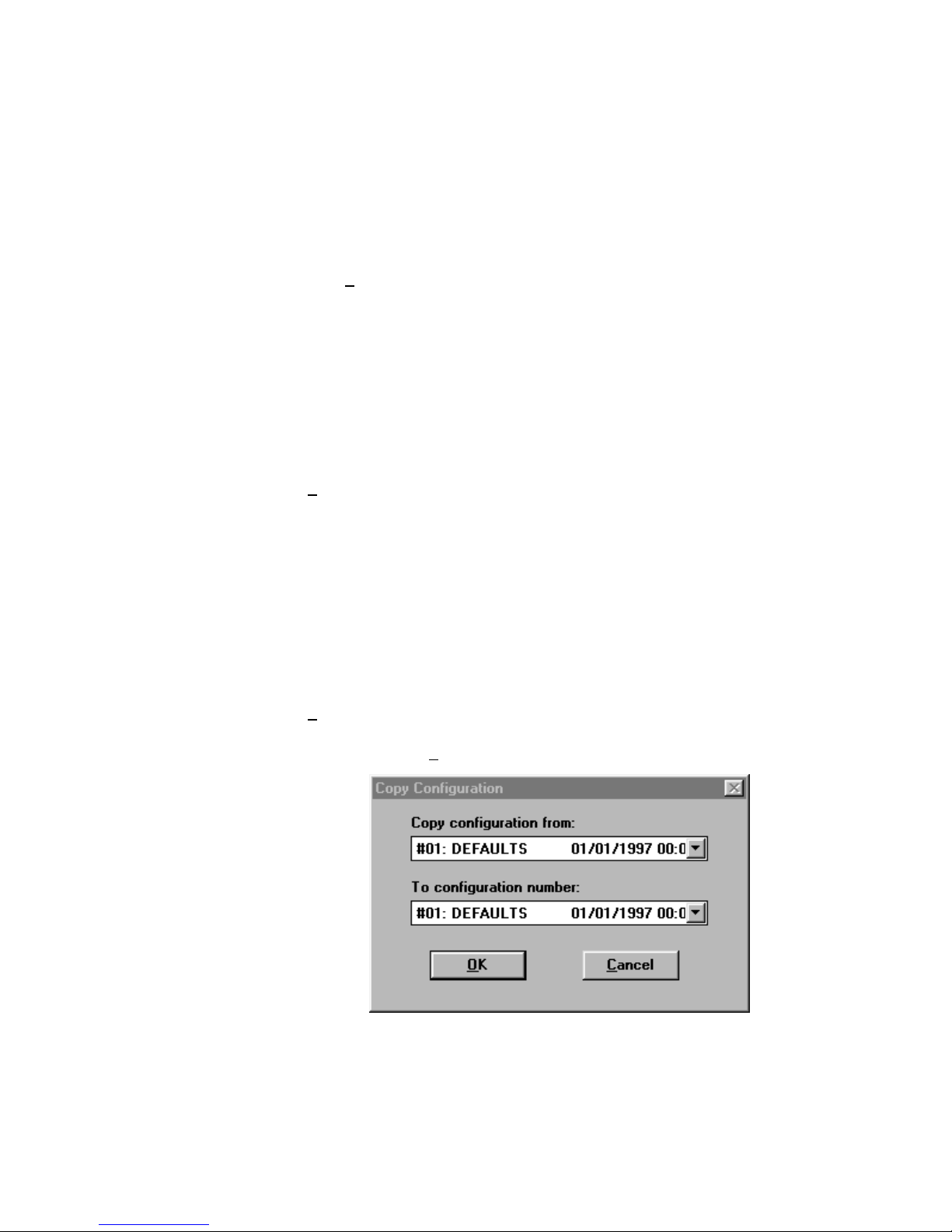
Copy Configurations
The Edit menu is used to copy settings from one configuration to another, or to copy the
settings from one Line to another by using the Copy Configuration and Copy Line
commands found in the E
dit Configuration menu.
Figure 6. Copy Configuration Screen
40-400-00020, Rev. M 12
Page 19

Telephone Line Emulator User’s Manual
Figure 7. Copy Line Screen
40-400-00020, Rev. M
13
Page 20
Telephone Line Emulator User’s Manual
Operational Screens
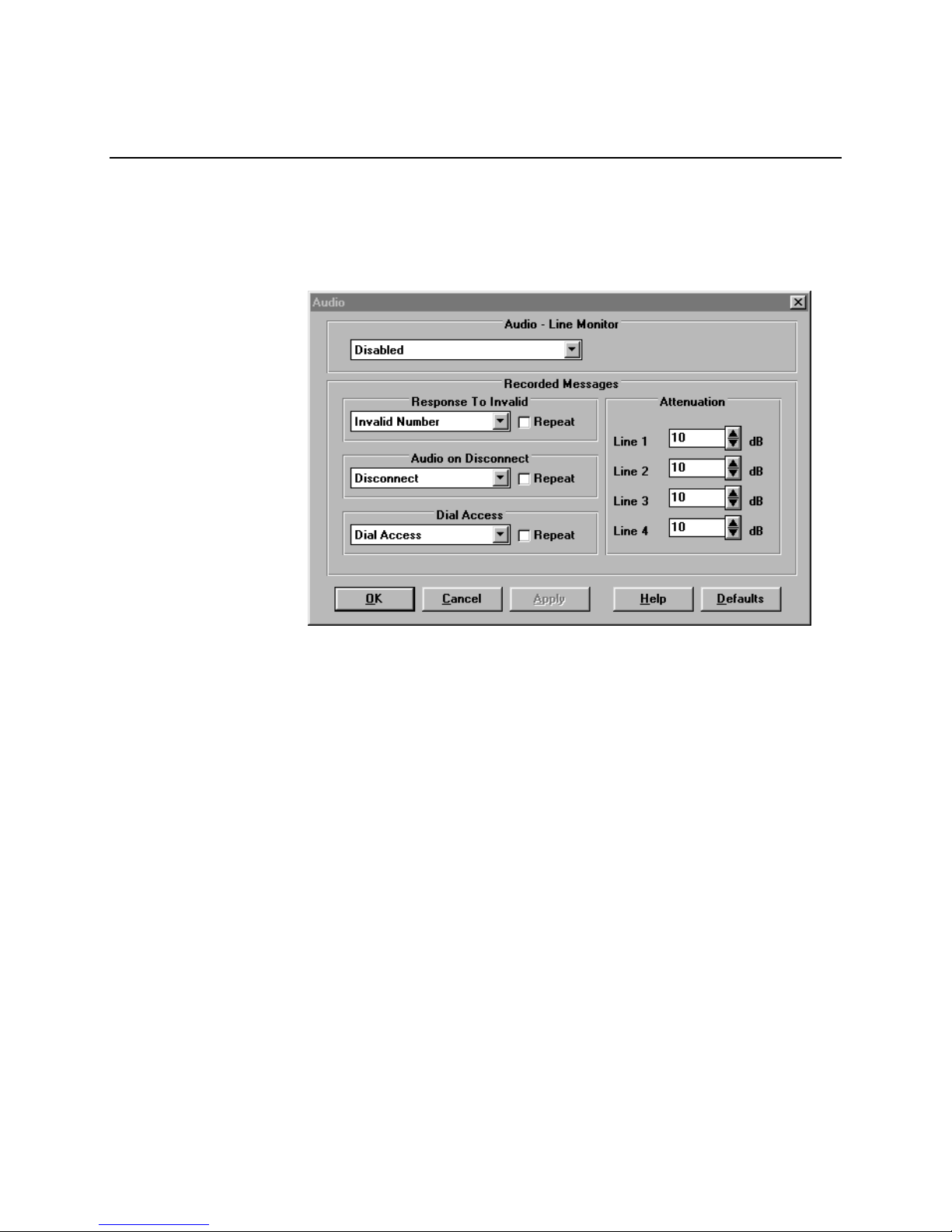
Audio Line Monitor
The Audio port on the front of the TLE is used to monitor the AC signals on any one of the
lines of the TLE when this feature is enabled. Only one line may be monitored at a time.
The audio line monitor port is a 3.5 mm miniature audio jack.
Figure 8. Audio Screen
Recorded Messages
The Recorded Messages portion of the Audio screen, together with the Voice
Messages screen, allows the selection of recorded messages for playback.
There are three conditions defined for playback: Invalid phone Number dialed,
Audio message on Disconnect, and message for Dial Access. There are four
messages which may be stored. The default names (see Voice Messages
screen) are: Invalid Number, Disconnect, Dial Access, and Alternate. Any of
these four names may be selected for the three conditions with the Audio
screen.
When one of the conditions for playback occurs, the recorded message plays
one time, followed by silence. If the Repeat selection is checked, the audio
message will repeat continuously.
The TLE ships with one default message for each of the three conditions. These
messages are stored in a mono 8 kHz, 8-bit µ-law WAV file format. Their names
are: Invalid.WAV, Hangup.WAV, and Dialacc.WAV. The user may create new
files using a sound card. Double clicking on the File field in the Voice Messages
screen allows the selection of a new file. The TLE-PC software stores these in
0.5 seconds increments and displays the total file length on the screen. The sum
40-400-00020, Rev. M 14
Page 21
Telephone Line Emulator User’s Manual
of all recorded messages must not exceed the total length for the audio memory
(8 seconds).
Attenuation
Attenuation is the loss of signal level. Attenuation values refer to the amount of
attenuation compared to the original recording.
Attenuation may be set from 0 dB to 60 dB in 1 dB increments.
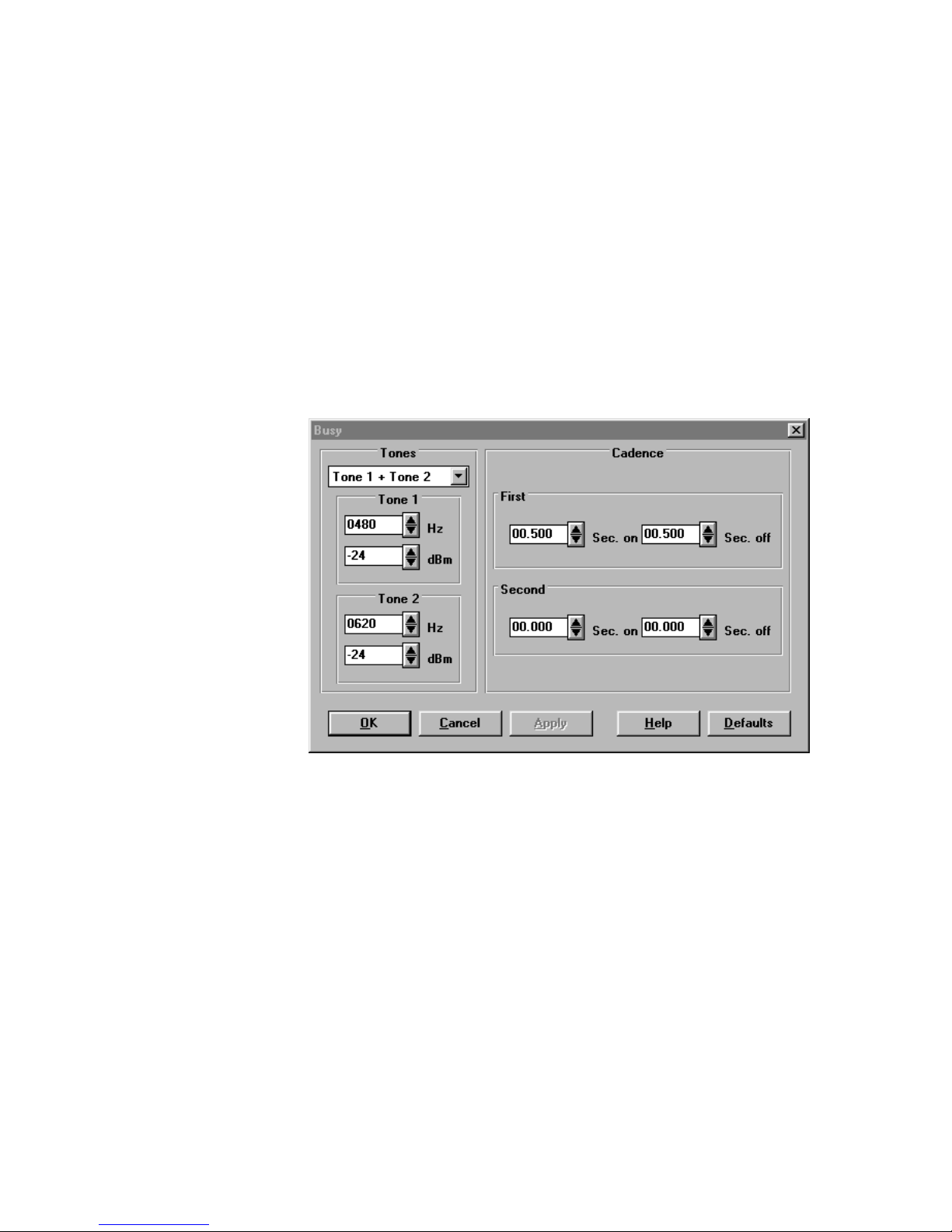
Busy Tone
The Busy signal is an indication that the Called Line is off-hook and not available. Busy
Tone has several variables, including: single tone or dual tone, output level, and a
simple or complex cadence.
Figure 9. Busy Screen
Busy Tone Levels and Frequencies
Busy Tones may be single or dual frequencies with individually adjustable amplitudes.
With a selection of Single Tone the system will only generate the first tone. With a
selection of Tone 1 + Tone 2 the system will generate both tones with the specified
frequencies and amplitudes. Purchase of the TLE-INTL Software Module adds the
selection of Tone 1 x Tone 2. The system will generate Tone 1 modulation by Tone 2. In
this implementation only the fundamental and upper side tone are generated, both at the
amplitude programmed for Tone 1.
For each tone, the frequency range may be set from 10 Hz to 1000 Hz in 1 Hz increments.
Output level may be set from -6 dBm to -60 dBm per tone in 1dB increments.
Busy Tone Cadence
First Cadence on time may be set from 100 mS to 2000 mS in 5 mS increments.
First Cadence off time may be set from 100 mS to 2000 mS in 5 mS increments.
40-400-00020, Rev. M
15
Page 22

Telephone Line Emulator User’s Manual
Second Cadence on or off time may be set from 0 mS to 5000 mS in 5 mS increments, or
may be set to 0 if only the First Cadence values are to be utilized.
If the Second Cadence values are 0, the unit will repeat with the First Cadence values.
If the Second Cadence values are programmed, the unit will repeat after going through all
four time values.
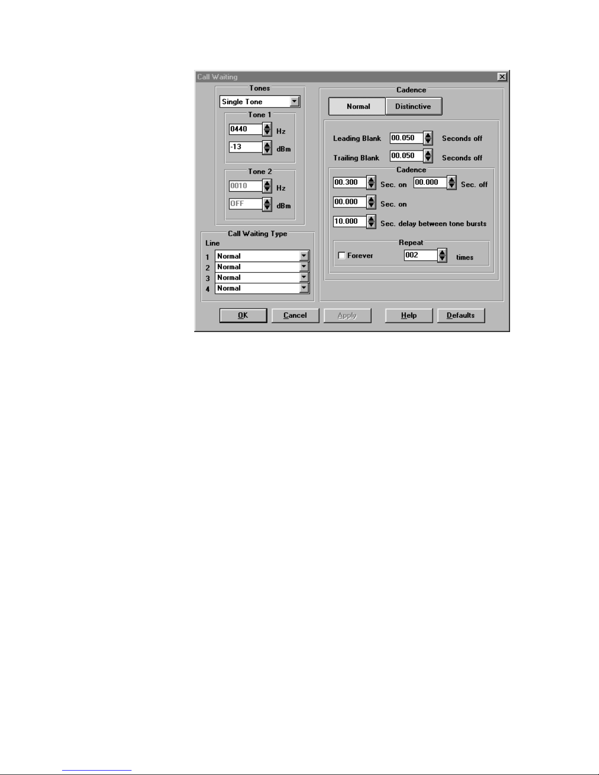
Call Waiting
The Call Waiting signal (a.k.a. SAS Tone, Subscriber Alerting Sequence) is an indication
that there is a calling party waiting for the called party to become available. The calling
party hears normal ringing and the called party hears a Call Waiting Tone that is repeated
once, 10 seconds after the first occurrence. The called party answers a Call Waiting by
either generating a FLASH, which places the existing caller on hold, or by hanging up on
the existing caller, after which the telephone will begin to ring again with the waiting caller.
In some Central Offices, a waiting caller is announced with a Normal single tone if the call
is local, and a Distinctive two tone sequence if the caller is calling from long distance.
Call Waiting With Caller ID Enabled (SCWID or CIDCW)
SCWID (Spontaneous Call Waiting with Caller ID) also known as CIDCW (Caller ID in Call
Waiting) is a function that sends the FSK data (Caller ID) after a Call Waiting Tone. This
data transmission burst is typically sent to a specially configured telephone or an adjunct
device that mutes the line to the local caller for the duration of the FSK burst. The format
of the message is always multiple message format, that is, the Name and Number are
sent to the called party. This feature is invoked whenever a third party places a call to an
existing call, if Caller ID is enabled and Cancel Call Waiting has not been enabled. When
a third party is calling, the called line will be momentarily isolated and will hear a Call
Waiting Tone (SAS tone), followed by a CAS tone to alert the Caller ID phone or adjunct.
If the Caller ID phone or adjunct issues a DTMF “D” (from non-ADSI CPE) or a DTMF “A”
(from ADSI CPE) acknowledgement tone, the FSK sequence is sent down the line for
Caller Identification. The called party may then ignore the Call Waiting, or generate a
flash to place the first caller on hold, and answer the Call Waiting. If the Called Party
ignores the first Call Waiting alerting sequence, it will be repeated once, ten seconds later.
If the called party answers the Call Waiting, they are allowed to alternate between callers
using the flash function. If one party hangs up, the remaining parties are automatically
connected.
Call Waiting with Caller ID Disabled
A user may want to have the TLE generate just the Call Waiting Tone (SAS tone) without
Caller ID or CAS tone. To have the TLE perform in this manner, go to the Caller ID
Screen and disable Caller ID for the line in use.
Cancel Call Waiting
The Call Waiting tone may be disabled on a per-call basis by dialing ∗70 or 70#, TLE
Response - Confirmation Dial Tone. (See Dial Tone screen.) Call Waiting will be reset
and enabled after the line is placed on-hook.
40-400-00020, Rev. M 16
Page 23
Telephone Line Emulator User’s Manual
Figure 10. Call Waiting Screen
The Call Waiting signal has several variables, including: Disabled, Single Tone or Dual
Tone, Type of Call Waiting Signal, and Cadence.
Call Waiting Tone Levels and Frequencies
Call Waiting Tones may be single or dual frequencies with individually adjustable
amplitudes. With a selection of Single Tone the system will only generate the first tone.
With a selection of Tone 1 + Tone 2 the system will generate both tones with the specified
frequencies and amplitudes. Purchase of the International Module adds the selection of
Tone 1 x Tone 2. The system will generate Tone 1 modulation by Tone 2. In this
implementation only the fundamental and upper side tone are generated, both at the
amplitude programmed for Tone 1.
For each tone, the frequency range may be set from 10 Hz to 1800 Hz in 1 Hz increments.
Output Level may be set from -6 dBm to -60 dBm per tone in 1 dB increments.
Call Waiting Type
Call Waiting Type may be programmed for each Line. Options are Disabled, Normal,
and Normal & Distinctive.
Call Waiting Cadence
Two Cadences are available: Normal and Distinctive.
Both Cadence on times may be set from 0 mS to 1500 mS in 5 mS increments.
Cadence off time may be set from 0 mS to 1500 mS in 5 mS increments.
Leading Blank, or the delay before the call waiting tone is sent, may be set from 5 to 100
mS off in 5 mS increments. (Default = 50 mS.)
40-400-00020, Rev. M
17
Page 24

Telephone Line Emulator User’s Manual
Trailing Blank, or the delay after the call waiting tone is sent, may be set from 20 mS to
100 mS off in 5 mS increments.
The Leading Blank time is the time from when the existing call is muted and the Call
Waiting starts. The Trailing Blank time is the time from when the Call Waiting stops and
the existing call is reconnected.
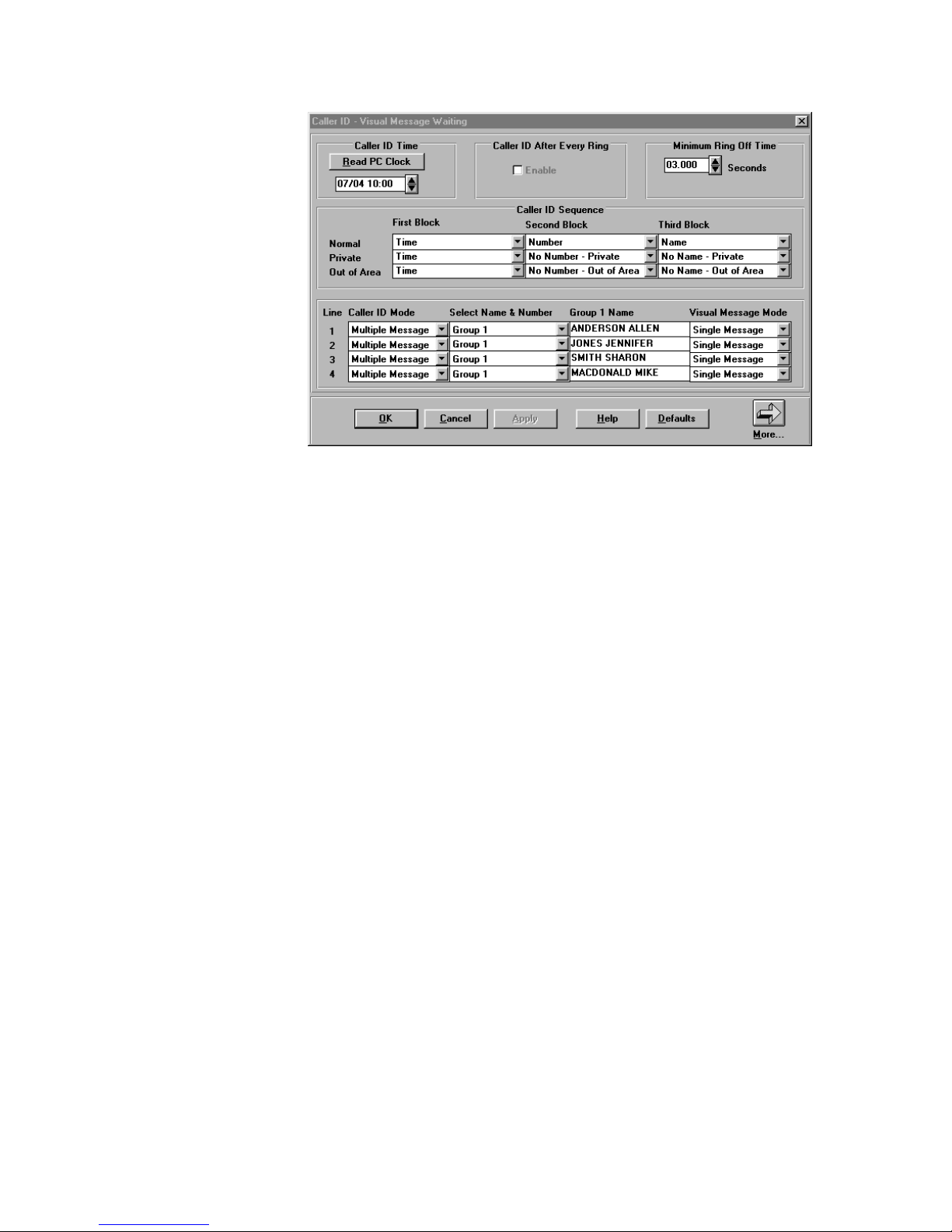
Caller ID - Visual Message Waiting
The Caller ID signal is an FSK signal sent at 1200 baud to alert the called party of the
identity of the calling party. This may consist of the telephone number only, (Single
Message Format), or a Name and Number (Multiple Message Format). The transmission
also includes a Date and Time, and issues a checksum at the end for error correction.
Special sequences include Out of Area ∗87 (indicates no available information for the
caller), Private ∗67 (Blocked Call) and an error message ∗88 (checksum error) when a
special prefix code is dialed before the normal telephone number. For testing and
development purposes, there is a special mode where the Caller ID is sent after every
ring. (TLE-ADV only.)
Visual Message Waiting is an FSK signal sent at 1200 baud to turn on a visual indicator
on an adjunct or Caller ID phone. This signal is sent during an on-hook state after an
open switch interval.
Turn ON the Visual Message Waiting Indicator using the following dial sequence;
Dial ∗50 + “Called Telephone Number”
Turn OFF the Visual Message Waiting Indicator using the following dial sequence;
Dial ∗51 + “Called Telephone Number”
Example: A Caller ID adjunct or display phone is connected to Line 2. From a telephone connected
to any other line, go off-hook and dial *50 102. The display for the called line will indicate
VMW sent during the time when FSK is generated after the Open Switch Interval.
Stuttered Dial Tone is issued to the called line until VMWI OFF is invoked or the Dial
Access Audio Message is dialed. Default is 411.
Note: The TLE-ICID Software Module is available as an upgrade to the TLE-INTL Software
Module. This upgrade module combines the Call Waiting screen and the Caller ID screen.
The TLE-INTL software will allow Caller ID to be enabled for other countries but it
conforms to the Bellcore (USA/Canada) standards.
40-400-00020, Rev. M 18
Page 25
Telephone Line Emulator User’s Manual
Figure 11. Caller - ID Visual Message Waiting Screen 1
Caller ID Time
This may be set either by the user or can be read from the PC clock. The TLE maintains
a real time clock only when power is on. Upon power up the date and time start at the
time as set by this field.
Caller ID After Every Ring
Caller ID After Every Ring is a feature that will send the FSK sequence after every
Power Ring Cycle. The Caller ID will be sent only if the minimum off time criteria is met.
(TLE-ADV and TLE-TEST Software Modules only.)
Minimum Ring Off Time
By default, the TLE must see a minimum of 3 seconds in the off portion of the Ring
Cadence, before Caller ID is sent. By programming this field to a shorter time, the user
can force a transmission during shorter Ring Off Time. The user must be aware that, for
shorter times, the entire FSK data burst may not be complete before the next ring cycle.
The Minimum Ring Off Time can be set from 0 seconds to 10 seconds in 5 mS
increments. Default is 3 seconds.
Caller ID Sequence
Caller ID Sequence is a feature that allows a user to select the sequence and information
that is sent with each Caller ID block using the Multiple Message Format. This is useful to
ensure that CPE devices may receive this data regardless of the order of the messages.
If a ∗67 prefix is dialed prior to the number, the Private sequence will be used.
If a ∗87 prefix is dialed prior to the number, the Out of Area sequence will be used.
If a ∗88 prefix is dialed prior to the number a checksum error is generated.
Otherwise, the Normal sequence will be used.
40-400-00020, Rev. M
19
Page 26

Telephone Line Emulator User’s Manual
Caller ID Mode
This feature allows the selection of the Caller ID Mode for each Line. The options include
Multiple Message format (default), Single Message format, or Disabled.
Select Name & Number
This feature allows the selection of one of three different Groups of Names and Numbers
(see Phone Numbers). The Names for Group 1 are programmable for up to 16
characters. The Names for Group 2 and 3 are fixed. The defaults for the Names follow
this paragraph.
Group 1 - Programmable names, uses Group 1 telephone numbers
Line 1 = ANDERSON ALLEN
Line 2 = JONES JENNIFER
Line 3 = SMITH SHARON
Line 4 = MACDONALD MIKE
Fixed names for Group 2, uses Group 2 telephone numbers
Line 1 = CLINTON BOB
Line 2 = REAGAN RICK
Line 3 = CARTER JOHNNY
Line 4 = FORD GARY
Fixed names for Group 3, uses Group 3 telephone numbers
Line 1 = MONTANA JIM
Line 2 = MARINO DON
Line 3 = AIKMAN TOM
Line 4 = KELLY JOHN
Group 1 Name
The Group 1 Name is programmable up to 16 characters. This is the name that is sent to
the Called Line from the Calling Line when Multiple Message format is used.
Visual Message Mode
This feature allows the selection of the Visual Message Mode for each Line. The options
include Multiple Message format (default), Single Message format, or Disabled.
40-400-00020, Rev. M 20
Page 27
Telephone Line Emulator User’s Manual
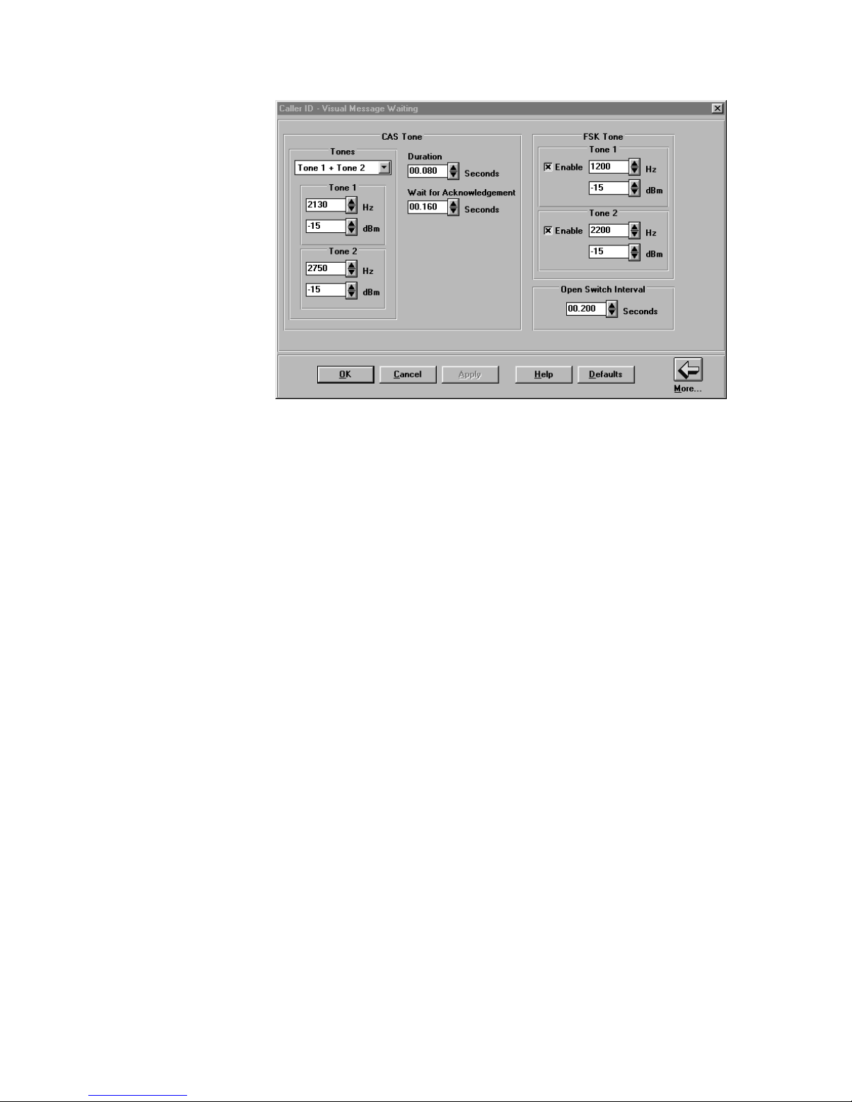
Figure 12. Caller ID Visual Message Waiting Screen 2
CAS Tone
CAS Tone is a CPE Alerting Signal; a Bellcore term for a tone used to alert CPE
equipment of Call Waiting, asking for ACKnowledgement prior to sending Caller ID. The
CAS Tone has several variables, including: Disabled, Single Tone or Dual Tone,
Duration, and Time to Wait for Acknowledgement.
With a selection of Single Tone the system will only generate the first tone. With a
selection of Tone 1 + Tone 2 the system will generate both tones with the specified
frequencies and amplitudes. Purchase of the International Module adds the selection of
Tone 1 x Tone 2. The system will generate Tone 1 modulation by Tone 2. In this
implementation only the fundamental and upper side tone are generated, both at the
amplitude programmed for Tone 1.
Frequency for Tone 1 and Tone 2 may be set from 10 Hz to 3000 Hz in 1 Hz increments
and -6 dBm to -60 dBm in 1 dBm increments.
Duration may be set from 70 mS to 90 mS in 5 mS increments.
After the TLE sends the CAS signal it waits a certain time for a DTMF ACKnowledgement
signal from the CPE device. If it sees this, it sends the FSK data. This Wait for
Acknowledgement time may be varied to ensure that CPE devices are responding within
the proper time window. Wait for Acknowledgement may be set from 100 mS to 300
mS in 5 mS increments.
FSK Tone
The FSK (Frequency Shift Key) Tones are programmable in both frequency and signal
level. The mark (1) tone is the lower of the two tones and is programmable from 1100 Hz
to 1400 Hz. The space (0) tone is the upper tone and is programmable from 2000 Hz to
2300 Hz. Both tone levels may be set from -10 dBm to -60 dBm in 1 dB increments.
40-400-00020, Rev. M
21
Page 28
Telephone Line Emulator User’s Manual
Open Switch Interval
The Open Switch Interval is a form of DC signaling, sent during an on-hook state, prior to
Visual Message Waiting. During this time, the -48 VDC is momentarily removed. Open
Switch Interval may be set from 0 seconds to 5 seconds in 5 mS increments.
Advanced Screen Telephony
ADSI, also known as Advanced Screen Telephony, a Type III Caller ID sequence, is
supported in the TLE using a special ADSI test number ∗∗99∗∗, which performs a script
download from the TLE. Three data bursts are sent from the TLE, shown in the display as
ADSI_ack1, ADSI_ack2, and ADSI_ack3 to load a script called “Call Management”.
This new service provides a limited script that will display “New Call From” and “Caller
ID”. After answer, the display changes to “Talking To” and “Caller ID” and a button
labeled “Don’t interrupt”. If the button is pressed, the CPE will perform a flash; dial ∗70
to disable Call Waiting and then displays “Call Waiting OFF”.
When the CPE receives a Caller ID during a call, the display will show “New Call From”
and “Caller ID”. The button selection will change to “Connect New Call”. If this button is
pressed, the original caller is placed “On Hold” and the button changes to “Reconnect
1st Call”.
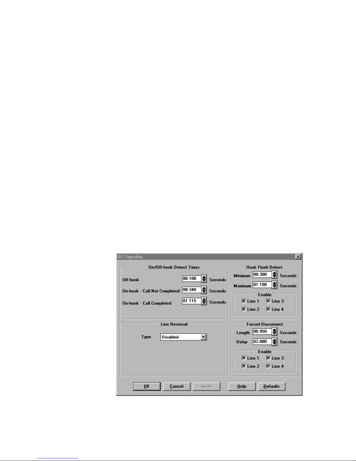
DC Signaling
DC Signaling changes polarity or loop current characteristics of the line. These include
On/Off-Hook Detect Times, Hook Flash Detect Time, Line Reversal, and Forced
Disconnect Length and Delay.
40-400-00020, Rev. M 22
Figure 13. DC Signaling Screen
Page 29

Telephone Line Emulator User’s Manual
On/Off-hook Detect Times
Off-hook Detect is the minimum duration that loop current must occur for a valid off-hook
condition. On-hook Detect is broken into two values. If a call has not been completed, for
example a busy number has been dialed, a short on-hook time is used. If a call has been
completed, a long on-hook time is used. This allows hook flashes to be recognized. If
hook flashes have been disabled, the TLE always uses the Call Not Completed timer
value for on-hook detection.
Off-hook Detect Times may be set from 100 to 3000 mS in 5 mS increments. On-hook
Detect may be set from 100 to 3000 mS in 5 mS increments.
Note: On-hook time must exceed Hook Flash time.
Hook Flash Detect
Hook Flash, a.k.a. FLASH and Switch Hook Flash, is a loss of loop current for a specific
duration that is used to request special features, such as Transfer, Conference, and Hold.
Hook Flash Detect Minimum and Maximum can be set from 75 mS to 1200 mS in 5 mS
increments.
Each line may be enabled or disabled for Hook Flash Detect.
Line Reversal
A line reversal is a signal that changes the polarity of the battery on the line subject to
certain conditions. These conditions may include Called Party Answer, Call Termination,
and others. Line Reversal Type is available as Disabled, Simple or Complex. (The
default is reversal disabled. This programming will apply to all lines.) When the unit is
programmed for Simple Line Reversal on an originating call, a line will perform a reversal
just prior to issuing dial tone. It will then remain at that state until it goes back on-hook, in
which case another reversal will be performed. For an incoming call a line will perform a
line reversal after it goes off-hook in response to ringing.
When the unit is programmed for Complex Line Reversal on an originating call, a line will
perform a momentary reversal just prior to issuing dial tone. The duration of the reversal
is programmable, and may range from 50 mS to 100 mS in 5 mS increments. On an
incoming and outgoing call a permanent line reversal will be performed at call completion.
Forced Disconnect
Forced Disconnect is a method used by the telephone company to clear a line. When the
called party goes on-hook, the Central Office returns an open (that is, drops loop current)
of at least 800 mS to the calling party. The TLE emulates Calling Party Control, in which,
if the calling party goes on-hook the called party receives a Forced Disconnect within 2
seconds. If the called party goes on-hook, the calling party receives a Forced Disconnect
which may occur some time greater than 2 seconds later. This timer is programmable, up
to 30 seconds. The actual Length of the Forced Disconnect is also programmable with
the default being 850 mS.
Forced Disconnect Length may be set from 0 to 2 seconds in 5 mS increments.
Forced Disconnect Delay may be set from 1.2 to 30 seconds in 5 mS increments.
This feature may be enabled or disabled for each line.
40-400-00020, Rev. M
23
Page 30
Telephone Line Emulator User’s Manual
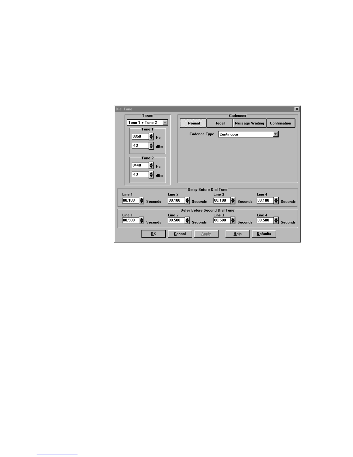
Dial Tone
Dial Tone is the audible signal issued to a calling party when the Central Office is ready to
receive digits. The TLE issues a Second Dial Tone after a series of digits are dialed to
emulate operation of a PABX or other switch platforms. (See Revert to Dial Tone phone
number.) Other types of dial tones include Recall Dial Tone (an interrupted Dial Tone,
a.k.a. Stuttered Dial Tone, indicating recognition of a FLASH Hook to access other
features), Message Waiting Dial Tone (an off-hook interrupted Dial Tone indicating
messages in voice mail), and Confirmation Dial Tone (an interrupted dial tone sequence
indicating that a feature has been properly used, such as Cancel Call Waiting).
Figure 14. Dial Tone Screen
Dial Tone Level and Frequencies
Dial Tones may be single or dual frequencies with individually adjustable amplitudes.
With a selection of Single Tone the system will only generate the first tone. With a
selection of Tone 1 + Tone 2 the system will generate both tones with the specified
frequencies and amplitudes. Purchase of the International Module adds the selection of
Tone 1 x Tone 2. The system will generate Tone 1 modulation by Tone 2. In this
implementation only the fundamental and upper side tone are generated, both at the
amplitude programmed for Tone 1.
Frequency for both tones may be set from 10 Hz to 1000 Hz in 1 Hz increments and signal
level from -06 dBm to -60 dBm in 1 dB increments.
Dial Tone Cadences
The TLE supports multiple dial tones. These include Normal, Recall, Message Waiting,
and Confirmation dial tones. Each dial tone may be configured for continuous, simple or
complex cadence.
Simple cadence has one on and one off time. Default is 0.1 seconds on, 0.1 seconds off.
Complex cadence has two separate on/off times. Default is 0.1 seconds on, 0.1 seconds
40-400-00020, Rev. M 24
Page 31

Telephone Line Emulator User’s Manual
off, 0.1 seconds on, 0.1 seconds off. The repeat number for both simple and complex
cadences can be set from 1 to 20. If the Repeat Forever box is not checked (on the Call
Waiting screen, continuous dial tone will follow the repeat sequence.
Delay Before Dial Tone
After going off-hook, this is the delay before dial tone is heard. It is programmable from 0
to 25 seconds. Default is 0.1 seconds.
Delay Before Second Dial Tone
Second Dial Tone is accessed by dialing the Revert to Dial Tone Phone Number
(programmed on the Phone Number Screen). This is the delay before the Second Dial
Tone is heard. It is programmable from 0 to 25 seconds. Default is 0.5 seconds.
Loop Parameters
Loop Parameters are those conditions that are directly related to the two wire loop:
Impedance, Attenuation, and Loop Current. Impedance matching is important for many
applications so that all signals sent to the switch network are absorbed and not reflected
back to the caller. Attenuation is the loss in signal level (measured in dB) that occurs from
one line to another. The TLE allows for programming of this loss on the receive side.
Signals transmitted to the TLE are not attenuated until they reach the connected line. The
TLE also allows for programming of the loop current, normally determined by the battery
feed and the length of the loop.
Impedance
Impedance options for the TLE allow each line to be configured for either 600 (600 + 2.2
µF) or 900 (900 + 2.2 µF) ohms. The default is 900 ohms. Users who purchase the TLEINTL software module ( V2.00 or greater) will get three additional options for Line
Impedance. These are the complex impedances for Australia, Germany, and the United
Kingdom. Version 3.00 now includes Sweden.
40-400-00020, Rev. M
Figure 15. Loop Parameters Screen
25
Page 32

Telephone Line Emulator User’s Manual
Line Receive Attenuation
This value is the attenuation of the audio signal received at a port. Line Receive
Attenuation may be set from 4 dB to 60 dB in 1 dB increments. These settings only
affect signals received from other lines. They do not affect internally generated tones,
e.g., Call Progress signals or Audio Playback.
Loop Current
Loop current is the amount of current that the TLE will supply to a device when it is offhook. Each line is programmable and may be set from 10 mA to 70 mA in 1 mA
increments ±10%.
When loop current is set from 16 to 70 mA, the TLE will declare an off-hook at
approximately 12 mA. When loop current is set from 10 to 15 mA, the TLE will declare an
off-hook at approximately 8 mA.
Miscellaneous
Miscellaneous signals include Disconnect Treatment, Confirmation Tones, Rotary Dial
Only, Conference Type, Test Tones, Off-Hook Mode, Hunt Mode, Invalid Number
Response, and Network Delay.
Disconnect Treatment
Disconnect Treatment is the audible signal that is heard by a party when the other parties
go on-hook. The options available include: Dial Tone, Busy, Reorder, Silence, and
Audio Message.
Confirmation Tones
Confirmation Tones are tones that are issued during access to the Programming Mode,
(accessed via ∗∗99## entry with a phone) when selecting a new Configuration, and
40-400-00020, Rev. M 26
Figure 16. Miscellaneous Screen
Page 33

Telephone Line Emulator User’s Manual
requesting version information from the TLE. After all valid and proper entries, a three
beep sequence is issued. After an invalid entry, a longer single tone is issued.
Rotary Dial Only
Rotary Dial Only operation is to be used when there is a need to accept only Rotary
Dialed (a.k.a. Pulse Dial) numbers. DTMF tones are still decoded during the first 30
seconds after power up for access to programming mode. (Only available with TLE-ADV
and TLE-TEST modules.)
Conference Type
Conference Type allows for two different operations when a Conference Call is
attempted. The differences in operation are detailed below (C.O. Conference is based
upon Three Way Calling):
A typical Conference Call is initiated by generating a FLASH, Recall Dial Tone is heard,
then a phone number is dialed to access the third (or fourth) party. If PBX Conference is
selected, the originator of the conference must wait until the party answers before
generating another Flash to bring all parties together.
• PBX Conference
Up to 4 lines may be connected in conference. The Called Party must answer
before the second Flash to connect parties. Any party may hang up and all
the others in the conference will remain connected
• Central Office Conference
Only three lines may be connected in a conference if a FLASH is generated before the
Called Party answers, the remaining parties will hear ringing. If the Originating Party
hangs up, all connections will be terminated
Test Tones
Test Tones is a user programmable single or dual tone that is accessed by dialing the
Special Test Tone Phone Number. This phone number is set on the Phone Number
screen. Default is 83785. With a selection of Single Tone the system will only generate
the first tone. With a selection of Tone 1 + Tone 2 the system will generate both tones
with the specified frequencies and amplitudes. Purchase of the International Module adds
the selection of Tone 1 x Tone 2. The system will generate Tone 1 modulation by Tone 2.
In this implementation only the fundamental and upper side tone are generated, both at
the amplitude programmed for Tone 1.
Frequency range is 10 to 3000 Hz and output level is -0 dBm to -60 dBm.
If the Test Tone is set for dual tone output, the maximum level should be limited to -6
dBm per tone.
Off-hook Mode
Off-hook Mode is how the TLE handles a call when a device connected to the line meets
the minimum Off-hook time. The options include: Normal (issues dial tone and waits for
dialing), Hotline (will automatically ring the number programmed into the Revert to Dial
Tone location), and Silent (will connect a device to a quiet Battery). Each line may be
programmed individually.
40-400-00020, Rev. M
27
Page 34

Telephone Line Emulator User’s Manual
Hunt Mode
Hunt Mode is how the TLE determines which line will ring when the same Phone Number
st
is programmed for multiple lines. The options include Ring All (default), Ring 1
st
Ring 1
Available, and Ring Next. Each Line may be programmed individually.
Match,
When the unit is set to Ring All, all lines with the same phone number will ring. When it is
set for Ring 1st Match, the TLE will only ring the first line which has this number
programmed. If that line is busy then a busy signal will be returned. When the Hunt
Mode is set to Ring 1st Available it will start from line 1 and ring the first line that is idle,
skipping over busy lines. When the Hunt Mode is set to Ring Next Available, it will ring
the next higher line number after the last one used (e.g., if line 2 was the last line rung,
line 3 will be rung).
For all Hunt Modes, all numbers in a Hunt Group must be programmed with the same
number group. (i.e., 101, 102, 103, 104 together or 201, 202, 203, 204 together, etc.).
Invalid Number Response
Invalid Number Response is the signal that is sent to a caller when an invalid number is
dialed, that is, one that does not match any of the programmed Phone Numbers in the
TLE. The options include SIT (Special Information Tones), Reorder, Ringback, Silence,
and Audio (a stored audio message). Each line may be programmed individually. When
SIT is selected the unit will output SIT, followed by the Audio message.
Network Delay
Phone Numbers
Note: Care should be taken that NO Phone Number starts as a subset of another, except for the
Network Delay is a timer that is used after a dialed sequence is complete before the TLE
issues any network responses, such as Ringback, Busy, Reorder, or Audio. Each line
may be programmed individually from 0 to 25 seconds in 5 mS increments.
Phone Numbers are used to access each Line, Revert to Dial Tone (a.k.a. 2nd Dial Tone),
and Test Tones (Dial Tone, Busy, Reorder, Ringback, Special Test Tone, and Stuttered
Dial Tone). Each Phone Number is programmable from 0 to 16 digits in length.
Revert to Dial Tone Number. For example, line 1’s default phone number is 101. You
cannot program another phone number to be 1015.
40-400-00020, Rev. M 28
Page 35

Telephone Line Emulator User’s Manual
Figure 17. Phone Numbers Screen
Revert to Dial Tone
The Revert to Dial Tone number is programmable from 0 to 16 digits in length. When this
number is dialed a second dial tone is heard. Default is 9.
Dial Tone - Test Number
This is the telephone number dialed to access a continuous Normal Dial Tone as
programmed in the Dial Tone screen. The telephone number is programmable from 0 to
16 digits in length and the default setting is 83781.
Busy - Test Number
This is the telephone number dialed to access a continuous Busy signal programmed in
the Busy screen. The telephone number is programmable from 0 to 16 digits in length
and the default setting is 83782.
Reorder - Test Number
This is the telephone number dialed to access a continuous Reorder tone programmed in
the Reorder screen. The telephone number is programmable from 0 to 16 digits in length
and the default setting is 83783.
Ringback - Test Number
This is the telephone number dialed to access a continuous Ringback tone programmed
in the Ringing screen. The telephone number is programmable from 0 to 16 digits in
length and the default setting is 83784. In the TLE, ringback is always synchronized with
the ring signal at the called line.
40-400-00020, Rev. M
29
Page 36

Telephone Line Emulator User’s Manual
Special Test Tone - Test Number
This is the telephone number dialed to access the Special Test Tone programmed in the
Miscellaneous screen under Test Tones. It is programmable from 0 to 16 digits in length
and the default setting is 83785. The default test tone is 1004 Hz at -10 dBm.
Stuttered Dial Tone - Test Number
This is the telephone number dialed to access the Stuttered Dial Tone programmed in
the Dial Tone screen under Confirmation. It is programmable from 0 to 16 digits in
length and the default setting is 83786.
Port Configuration
By default the TLE operates as a 4 line unit with a single Active Configuration. Under this
scenario there are certain global parameters which apply to all lines, for example, Call
Progress frequencies, such as Dial Tone or SIT.
Independent switch operation, ports 2 & 4 is a special mode to allow for more versatile
programming of the TLE. When this mode is selected, the unit will operate with one
configuration for ports 1 and 3 and a second configuration for ports 2 and 4. To edit a
port’s parameters, the appropriate configuration must first be selected as the Edit
Configuration. However, for certain global parameters, such as date/time for Caller ID, the
TLE can only accept one value. In these cases, the unit will always use the values from
the first configuration – the edit function is disabled for these parameters in the second
configuration.
Port Configuration allows the user to change the Edit Configuration from 4 Port (normal)
operation to 2x2 Port (dual two-port) operation with Lines 1 and 2 acting as a separate
platform that is isolated from Lines 3 and 4. The Clone operation can be used to make
the two-port platforms identical by copying the non-global parameters from Lines 1 and 2
over to Lines 3 and 4.
Figure 18. Port Configuration Screen
40-400-00020, Rev. M 30
Page 37

Telephone Line Emulator User’s Manual
Clone
Clone is used when configuring the TLE for 2x2 operation. Enabling this feature will clone
(or copy) an exact duplicate of the settings for Lines 1 & 2 to Lines 3 & 4 so that the Edit
Configuration is split into two identical setups. After the 2x2 Ports is selected, and the
screen is closed (OK) the Clone feature is disabled. To enable the Clone feature again,
select 4 Ports, then 2x2 Ports. A dialog box will appear. To Clone lines 1 & 2 to Lines 3
& 4, select Yes.
Reorder
The Reorder signal is an indication that trunk circuits are not available. Reorder Tone has
several variables, including: Single Tone or Dual Tone, Output Level, and a Simple or
Complex Cadence.
Figure 19. Reorder Screen
Reorder
Reorder tones may be single or dual frequencies with individually adjustable amplitudes.
With a selection of Single Tone the system will only generate the first tone. With a
selection of Tone 1 + Tone 2 the system will generate both tones with the specified
frequencies and amplitudes. Purchase of the TLE-INTL Software Module adds the
selection of Tone 1 x Tone 2. The system will generate Tone 1 modulation by Tone 2. In
this implementation only the fundamental and upper side tone are generated, both at the
amplitude programmed for Tone 1.
Frequency range for both tones may be set from 10 Hz to 1000 Hz in 1 Hz increments.
Output level may be set from -6 dBm to -60 dBm per tone in 1 dB increments.
Reorder Cadence
First Cadence on time may be set from 100 mS to 1000 mS in 5 mS increments.
40-400-00020, Rev. M
31
Page 38

Telephone Line Emulator User’s Manual
First Cadence off time may be set from 100 mS to 1000 mS in 5 mS increments.
Second Cadence on time may be set from 100 mS to 1000 mS in 5 mS increments.
Second Cadence off time may be set from 100 mS to 1000 mS in 5 mS increments.
If the Second Cadence values are programmed to zero the unit will repeat the sequence
with the first cadence values.
Ringing
Ringing is the AC voltage that is applied to a Line to alert a device to an incoming call. A
minimum ring signal (according to Bellcore) is 40 VAC RMS at 1 REN. The variable
parameters available in the TLE include Ring Frequency, Voltage Level, and Cadence.
Ring Cadence is programmable for each of the three groups of Telephone Numbers in 1,
2, or 3 On/Off sequences (a.k.a. Ring Cycle, Ringing Period). Telephone numbers 1, 2,
and 3 are set on the Phone Numbers screen.
Ringing - Lines 1, 2, 3, 4
Ring frequency may be set from 17 Hz to 70 Hz in 1 Hz increments. Ring voltage may be
set from 20 Volts AC RMS to 80 Volts AC RMS in 5 Volt increments.
The actual ring voltage seen at T/R will depend on (REN) ringer equivalence of the load.
40-400-00020, Rev. M 32
Figure 20. Ringing Screen
Page 39

Telephone Line Emulator User’s Manual
Cadence - Group 1, 2, 3
Cadence may be set for 1, 2 or 3 sequences from 0 to 3 seconds on and 0 to 10 seconds
off in 5 mS increments.
Ringback
Ringback is the audible tone heard by a caller while ringing is applied to the called line.
The TLE Ringback tone will match the Ring cadence of the Line called and is
programmable as a single or dual frequency with programmable levels and is applied to all
lines. With a selection of Single Tone the system will only generate the first tone. With a
selection of Tone 1 + Tone 2 the system will generate both tones with the specified
frequencies and amplitudes. Purchase of the TLE-INTL Software Module adds the
selection of Tone 1 x Tone 2. The system will generate Tone 1 modulation by Tone 2. In
this implementation only the fundamental and upper side tone are generated, both at the
amplitude programmed for Tone 1.
Frequency range for Tone 1 and Tone 2 may be set from 10 Hz to 1000 Hz in 1 Hz
increments.
Output Level may be set from -6 dBm to -60 dBm per tone in 1 dB increments.
Special Information Tones/Number Unobtainable Tone
SIT (Special Information Tones) consists of three tones that are generated by the network
when an abnormal condition exists. These have evolved over time to be primarily used
before audio announcements that indicate “All circuits are busy, please try your call again
later”, “The number you have dialed is no longer in service”, and other audio
announcements. The TLE allows the programming of the Frequency, Signal Level, and
On/Off Durations for these tones.
Countries other than US/Canada may use a Number Unobtainable Tone response. This
feature is available when the TLE International Module is purchased.
Figure 21. Special Information Tones/Number Unobtainable Tone Screen
40-400-00020, Rev. M
33
Page 40

Telephone Line Emulator User’s Manual
Frequency range for all three tones may be set from 10 Hz to 2000 Hz in 1 Hz increments.
Signal level may be set from -6 dBm to -60 dBm in 1 dBm increments.
On duration may be set from 0 to 10.000 seconds in 5 mS increments.
Off duration may be set from 0 to 10.000 seconds in 5 mS increments.
Note: For Number Unobtainable Tone Information, go to TLE-INTL Software Module
section.
Voice Messages
Voice Messages are audible signals that are stored internally in the TLE in a 8.000 kHz 8bit µ-law WAV file format. These are capable of being imported via the serial port. Initial
support is for 4 messages with a maximum total length of 8 seconds broken into 0.5
second blocks. Message names include Invalid Number, Disconnect, Dial Access, and
Alternate.
Figure 22. Voice Messages Screen
Invalid Number
The default message for Invalid Number is:
“The number you have dialed is incorrect. Please hang up and dial again.”
This message will be played when any invalid phone number is dialed.
Disconnect
The default message for Disconnect is:
“Please hang up.”
Dial Access
The default for Dial Access is:
“Today’s message is: Buy Teltone products.”
Alternate
The Alternate message is programmable with no default set.
40-400-00020, Rev. M 34
Page 41

Telephone Line Emulator User’s Manual
References
Teltone has used the following references in the development of the TLE-BASE and the
TLE-ADV software:
[1] TR-TSY-00064 LSSGR Issue 2, Section 6, (Signaling)
[2] TR-NPL-000275 BOC Notes on the LEC Networks (BNLN), Issue 2,
April 1994
[3] GR-30-CORE, Bellcore Publication, LSSGR: Voiceband Data Transmission
Interface, Section 6.6, Issue 1, 12/94
[4] TR-NWT-000030, Bellcore Publication, Voiceband Data Transmission Interface
Generic Requirements, Issue 2, 10/92
[5] TR-NWT-000031, Bellcore Publication, CLASS Feature: Calling Number Delivery
(CND), Issue 4, 12/92
[6] TR-NWT-001188, Bellcore Publication, CLASS Calling Name Delivery Generic
Requirements (CNAM), Issue 1, 12/91
[7] TR-NWT-001401, Bellcore Publication, Visual Message Waiting Indicator
Generic Requirements FSD 01-02-2000, Issue 1, 9/93
[8] SR-INS-002461, Bellcore Publication, Customer Premise Equipment
Compatibility Considerations for the Analog Display Services Interface, Issue 1, 12/92
[9] TR-NWT-001273, Bellcore Publication, Generic Requirements for an SPCS CPE
Data Interface for Analog Display Services, Issue 1, 12/92
[10] SR-NWT-002495, Bellcore Publication, Guidelines for Writing Applications Which
Use the Analog Display Services Interface (ADSI) for Data Communications, Issue 1,
12/92
[11] GR-416-CORE, Bellcore Publication, CLASS Feature: Call Waiting Deluxe, Issue
1, 4/95
40-400-00020, Rev. M
35
Page 42

Telephone Line Emulator User’s Manual
Advanced Emulation Software Module (TLE-ADV)
The TLE Advanced Emulation Module provides 16 different configuration settings, the
ability to enable Caller ID after every ring and the ability to disable DTMF detection. In
addition, this module provides emulation of impairments, metering tones, and the ability to
measure signal level. This module is sold separately. See the Ordering Information
section of this manual for details.
Note: This upgrade requires a software key that is generated by Teltone when the user supplies
the TLE Unit ID and the TLE-ADV serial number to Teltone. The instructions are included
on the Application Guide with the upgrade module.
Rotary Dial Only
Rotary Dial Only operation is to be used when there is a need to accept only rotary dialed
(a.k.a. pulse dial) numbers. DTMF tones are still decoded during the first 30 seconds after
power up. This feature is programmed on the Miscellaneous screen.
Caller ID After Every Ring
Impairments
Caller ID After Every Ring is a feature that will send the FSK sequence after every
Power Ring Cycle. This feature is programmed on the Caller ID screen (TLE-ADV and
TLE-ICID modules only.)
Echo
Echo is a reflection of the signal from a connected device back to that equipment. The
Echo Delay can be set from 0 to 100 mS in 125 µS (default is 0). The Attenuation,
relative to the strength of the original signal, can be set from 4 dB to 60 dB (default is 60
dB). Level accuracy will be maintained within ± 1 dB of setting.
White Noise
The White Noise operation provides a uniformly distributed noise source which is band
limited, starting at approximately 3.4 kHz. White Noise can be enabled for each line.
Default is disabled. If enabled, the White Noise volume can be set from 20 dBrn to 85
dBrn (default is 20 dBrn).
Noise source is broadbanded over 300 to 3400 Hz range (no C message weight). Level
accuracy is ± 2 dB for values from 20 to 85 dBrn.
40-400-00020, Rev. M 36
Page 43

Telephone Line Emulator User’s Manual
Figure 23. Impairments Screen
Satellite Delay
Satellite Delay emulates the time it would take a signal to travel from one satellite earth
station to the satellite then back to another satellite earth station. Satellite Delay can be
set from 0 to 1000 mS in 125 µS increments (default is 0).
Metering Tones
Satellite Delay must be set for all lines with the same delay. This implementation will also
provide a far end echo due to mismatch of the line and device impedance at the far end.
This effect may be minimized by increasing the line attenuation for both lines in the
connection.
Metering Tones are primarily used in international applications. These tones are provided
to customers when they place a phone call indicating what rate they will be billed for the
call. Each line can be programmed to enable or disable Metering Tones.
Figure 24. Metering Tones Screen
The frequency of the tone can be set at 16 kHz or 12 kHz.
The voltage of the tone can be set from 0 to 5 Vrms in 100 mV increments (default is 3
Vrms).
40-400-00020, Rev. M
37
Page 44

Telephone Line Emulator User’s Manual
The tone cadence can be set from 0 to 10 seconds on, and 0 to 10 seconds off in
5 mS increments (default is 0.5 seconds on, 0.5 seconds off).
If both lines have them enabled, Metering Tones are sent to both parties in the
connection.
Signal Level Measurement
This screen displays the amplitude of a signal in either dBm or mV. The TLE must be
connected to the PC to measure and display the signal level.
Figure 25. Signal Level Measurement Screen
Note: This screen is visible only if TLE-ADV is installed and the TLE hardware is connected.
The LED at the top of the screen will blink between red and green once per second
indicating the PC is receiving data from the TLE. The signal level can be displayed as a
time-averaged RMS reading, or the maximum/minimum during the sample period. The
measurement will continue until the Stop button is pressed or the screen is closed. The
value displayed will correspond to the signal within the telco audio band (roll off at
approximately 3.4 kHz).
40-400-00020, Rev. M 38
Page 45

Telephone Line Emulator User’s Manual
International Software Module (TLE-INTL)
The TLE International Software Module includes 11 preset country configurations and 5
settings preset to North America. An additional 11 countries are also included with the
software and are installed when the ‘Sample Configuration Files’ option is selected during
the software installation process.
The TLE-INTL Software Module is an upgrade to the TLE Base unit which provides certain
default country specific operational characteristics. These include: line impedance, ringing
cadence, ringing voltage, ringing frequency, call progress levels, call progress
frequencies, call progress cadences and line reversal. When this module is resident, the
TLE stores the programming of up to 16 configurations, versus only two configurations in
the TLE Base unit.
The default countries supported (one per configuration) are: Australia, Brazil, France,
Germany, Ireland, Japan, Korea, Netherlands, Singapore, Sweden, United Kingdom, and
US/Canada. The remaining four configurations are configured for US/Canada. The
additional country configurations available are Austria, Belgium, China, Denmark, Finland,
Greece, India, Italy, Norway, Spain and Switzerland.
This module is compatible with all features of the base unit, and may be co-resident with
the TLE-ADV Software Module.
Note: The TLE-INTL Software Module allows Caller ID to be enabled for other countries, but it
Rotary Dialing
Note: This upgrade requires a software key that is generated by Teltone when the user supplies
conforms to the Bellcore (USA/Canada) standards to support other Caller ID standards.
The TLE-ICID Software Module is available as an upgrade to the TLE-INTL.
The TLE rotary dial algorithm will allow the detection of the two most common rotary dial
specifications:
1. 40 mS/60 mS make/break ratio (U.S., Germany, Sweden, etc.)
2. 33 mS/67 mS make/break ratio (U.K., France, Ireland, etc.)
The digit translation will follow the U.S. standard (digit 1 = 1 pulse, digit 2 = 2 pulses, etc.)
for all countries.
the TLE Unit ID and the TLE-INTL serial number to Teltone. The instructions are included
on the Application Guide with the upgrade module.
40-400-00020, Rev. M
39
Page 46

Telephone Line Emulator User’s Manual
References
Teltone has used the following references for each of the countries specified,
however, you may find that certain parameters may be different for any
specific country. It is up to the user to verify that operating parameters are
valid for their application and usage.
[1] TR-TSY-000064 LSSGR Issue 2, Section 6, (Signaling)
[2] TR-NPL-000275 BOC Notes on the LEC Networks (BNLN),
Issue 2, April 1994
[3] GR-30-CORE, Bellcore Publication, LSSGR: Voiceband Data Transmission
Interface, Section 6.6, Issue 1, 12/94
[4] ITU Fascicle II.2, Recommendation E.180, Supplement #2, 1/94, Telephone
Network and ISDN - Operation, Numbering, Routing, and Mobile Services - Various Tones
Used in National Networks
[5] ETSI, European Telecommunications Standard, (ETS300-001), Attachments to
the Public Switched Telephone Network; General technical requirements for equipment
connected to an analogue interface in the PSTN (Candidate NET 4), March 1992.
Reset to Defaults
Note: When the front panel Reset button is pressed, the unit will be reset to the US/Canada
[6] British Standard BS 6305: 1992, General requirements for apparatus for
connection to the public switched telephone network run by certain public
telecommunications operators.
[7] Swedish Specification TVT 8211-A 112E, Technical requirements for connection
of subscriber equipment to the public switched telephone network.
[8] Singapore TAS TS PSTN 1, Issue 3 Rev 4, 1 April 1997, Approval Specification
for terminal equipment for connection to Public Switched Telephone Network & Analogue
Leased Circuits.
[9] Japan Approvals Institute for Telecommunications Equipment web site:
(accessed 9/29/97) http://www.sphere.ad.jp/jate/english. Overview of Technical
Conditions, Conditions specific to Analog Telephone Terminals. Ordinance Concerning
Terminal Facilities, Terminal Facilities to be Connected to Telephone Circuit Facilities.
defaults for all 16 configurations (country codes). The user must perform “Defaults” and
“Send All” from the PC configuration software to reload the defaults for each individual
country.
40-400-00020, Rev. M 40
Page 47

Telephone Line Emulator User’s Manual
Country Screen
Figure 26. Country Screen
This screen copies the default values of the selected country into the current Edit
Configuration. For example, from the Main screen, under Edit Configuration, select
configuration “#16 DEFAULTS”. Then using the General Setup button or the S
down menu, select Country. Choose one of the stored countries default values to copy
into the current Edit Configuration, such as United Kingdom. After OK or Apply is
selected, a screen will appear requesting confirmation of your selection. Selecting OK will
copy the default values for the selected country into the current Edit Configuration. If
additional changes are made - it is recommended that the Name be changed, using the
Main screen Name button, to an appropriate name.
creens pull
Importing Additional Countries
The TLE maintains a maximum of 16 independent configurations. When you import a
country configuration file, the imported configuration replaces one of the existing 16
configurations.
To import additional country configurations, follow the steps below:
1. In the Edit Configuration area of the main TLE screen, select one of the 16
configurations. The configuration that you select will be replaced by the imported
additional country settings. To maximize the capabilities of the TLE, select a default
configurations (for example, #13 DEFAULTS).
Figure 27. Selecting a Configuration to be Replaced by the Additional Country
40-400-00020, Rev. M
41
Page 48

Telephone Line Emulator User’s Manual
2. Select the Import Single Configuration command on the File menu.
3. In the Import Single Configuration dialog box, select the country configuration file you
want to import (for example, Austria.tlc).
4. Click the OK button.
Figure 28. Importing a Single Configuration
Call Waiting
5. With the imported country configuration displayed in the Edit Configuration area of the
main TLE screen, click the Send button to download the configuration to the TLE.
Once a configuration is sent to the TLE, that configuration is stored in nonvolatile memory
and is retained until the TLE is told to load a different configuration. To use a
configuration, select it as the active configuration.
Because the imported files do not have unique default parameters, they reset
to another country’s parameters if the Defaults button is clicked. If the
Defaults button is clicked accidentally, click Query if you are in the main
screen or Cancel on any other screen; otherwise, you may send inappropriate
parameters to the TLE. You can only recover by importing the configuration
again or by manually correcting the altered parameters.
The Caller ID / release of TLE-PC software Version 3.00 supports Caller ID formats other
than Bellcore (USA/Canada) with an upgrade. The TLE-ICID, International Caller ID
module, is an upgrade to the TLE-INTL, International Signaling module. This module
supports variations based upon Bellcore, ETSI FSK, and ETSI DTMF Caller ID standards.
One variation is called Bellcore Plus, an expanded version based upon Bellcore that is
used in Australia and Singapore. This upgrade combines the Caller ID and Call Waiting
Screens from previous versions to allow many parameters to be programmed so that the
TLE will support almost all Caller ID variations around the world. Default configurations
are provided for the following countries; Australia, France, Germany, Netherlands,
Singapore, Sweden, United Kingdom, and USA/Canada. Other country configurations
may be available for download and import from the Teltone Web site at
http://www.teltone.com. Requests for other country configurations should be directed to
info@teltone.com.
40-400-00020, Rev. M 42
Page 49

Telephone Line Emulator User’s Manual
Metering Tones
The BS6305 document (UK) states that “Meter pulses are normally provided only by
special arrangement between the PTT and the user, but may be present whether or not
the supply of them has been requested.”
The other documents (ITU, Swedish TVT 8211-A 112E, Singapore TAS TS PSTN 1, etc.)
make no mention about the circumstances under which meter pulses are provided.
Therefore meter pulses will be off, by default, for all countries.
Metering Tones are primarily used in international applications. These tones are provided
to customers when they place a phone call indicating what rate they will be billed for the
call. Each line can be programmed to enable or disable Metering Tones.
Figure 29. Metering Tones Screen (TLE-INTL)
The frequency of the tone can be set at 16 kHz or 12 kHz.
The voltage of the tone can be set from 0 to 5 Vrms in 100 mV increments (default is 3
Vrms).
The tone cadence can be set from 0 to 10 seconds on, and 0 to 10 seconds off in 5 mS
increments (default is 0.5 seconds on, 0.5 seconds off).
If both lines have them enabled, Metering Tones are sent to both parties in the
connection.
Special Information Tones/Number Unobtainable Tone
When a subscriber dials an invalid number, the method used to alert the subscriber varies
from country to country. Some countries return a Number Unobtainable Tone, some
return Special Information Tones, some return a recorded announcement, and some
return SIT tones followed by a recorded announcement. The use of SIT tones seems to
be evolving as an international standard, with some countries currently using Number
Unobtainable Tone, but planning to use SIT in the future. In the TLE, under the Special
Information Tone/Number Unobtainable Screen, the user must select either Special
Information Tone or Number Unobtainable for all lines. Then in the Miscellaneous
screen under Invalid Number Response they may select a particular response, on a per
line basis.
40-400-00020, Rev. M
43
Page 50

Telephone Line Emulator User’s Manual
Figure 30. Special Information Tones/Number Unobtainable Tone Screen
These tones are programmable as a single or dual frequency with programmable levels
and is applied to all lines. With a selection of Single Tone the system will only generate
the first tone. With a selection of Tone 1 + Tone 2 the system will generate both tones
with the specified frequencies and amplitudes. Purchase of the TLE-INTL Software
Module adds the selection of Tone 1 x Tone 2. The system will generate Tone 1
modulation by Tone 2. In this implementation only the fundamental and upper side tone
are generated, both at the amplitude programmed for Tone 1.
Frequency range may be set from 10 Hz to 2000 Hz in 1 Hz increments.
Signal level may be set from -6 dBm to -60 dBm in 1 dB increments.
On duration may be set from 0 Seconds to 10.000 Seconds in 5 mS increments.
Off duration may be set from 0 Seconds to 10.000 Seconds in 5 mS increments.
40-400-00020, Rev. M 44
Page 51

Telephone Line Emulator User’s Manual
Loop Parameters (TLE-INTL)
Complex Impedance
The TLE Loop Parameters were upgraded in the TLE-INTL module in TLE_PC software
release Version 2.00. This upgrade, to the TLE Loop Parameters, has added complex
impedance’s for Australia, Germany, and the United Kingdom. These parameters are
loaded into the programmable SLIC used in the TLE. The details include:
Australia: 220Ω +(820Ω || 120nF)
Germany: 220Ω +(820Ω || 115nF)
(This complex impedance is also used in Switzerland.)
Sweden: 270 Ω + (750 Ω || 150 nF) (Version 3.00 or greater)
United Kingdom: 370Ω + (620Ω || 310nF)
(This complex impedance is also used in Ireland.)
Country Default Settings
The following pages list all the available country default settings.
Figure 31. Loop Parameters (TLE-INTL)
40-400-00020, Rev. M
45
Page 52

Telephone Line Emulator User’s Manual
Australia Defaults
The settings for this country will be stored in configuration #2.
Dial Tone:
Frequency: 425 Hz x 25 Hz (425 HZ modulated by 25 Hz)
Level: -10 dBm
Cadence: Continuous
Busy Tone:
Frequency: 400 Hz
Level: -10 dBm
Cadence: 375 mS on/375 mS off
Reorder Tone:
Frequency: 400 Hz
Level: -10 dBm
Cadence: 375 mS on/375 mS off, alternate level reduced by 10
dB
Ringing Tone:
Frequency: 400 Hz
Level: -10 dBm
Cadence: .4 S on/.2 S off/.4 S on/ 2 S off
Ringing:
Frequency: 25 Hz
Amplitude: 70 VRMS
Cadence: .4 S on/.2 S off/.4 S on/ 2 S off
SIT or Number Unobtainable:
Frequency: 400 Hz
Level: -10 dBm
Cadence: 2.5 S on/.5 S off
Comments: Australia uses Number Unobtainable tone or
recorded announcement will use announcement as
default
Call Waiting Tone:
Frequency: 425 Hz
Level: -10 dBm
Cadence: .1 S on/.1 S off/.1 S on every 4.7 sec
Line Impedance: Australia 220Ω +(820Ω || 120nF)
Line Reversal: Disabled
40-400-00020, Rev. M 46
Page 53

Telephone Line Emulator User’s Manual
Austria Defaults
To make the settings for this country available, follow the instructions in
“Importing Additional Countries” on page 41.
Description Frequency (Hz) Cadence*1 Signal level
Dial Tone 420 // 450 Continuous -26dBm to -16dBm
Recall Dial Tone 420 Continuous -26dBm to -16dBm
Special Dial Tone 380 + 420 Continuous -26dBm to -16dBm
Ringing Tone 420 // 450 1.0(on)-5.0(off) -43dBm to -
6.5dBm
Ringing Signal 50 1.0(on)-5.0(off) 26Vac to 66Vac
Busy Tone I 420 // 450 0.4(on)-0.4(off) -43dBm to -
6.5dBm
Busy Tone II 420 // 450 0.3(on)-0.3(off) -43dBm to -
6.5dBm
Congestion Tone 420 // 450 0.2(on)-0.2(off) -43dBm to -16dBm
SIT Tones 950 0.33(on) -43dBm to -9dBm
1400 0.33(on) -43dBm to -9dBm
1800 0.33(on)-1.0(off) -43dBm to -9dBm
Call Waiting Tone 420 0.04(on)-1.95(off) -36dBm to -10dBm
Metering Tones 12 000 0.05(on)-0.05(off) 50mV to 2.5V
Impedance: 600 Ω
fff//fff is defined because some exchanges use the first frequency and is the default, and
other exchanges use the second frequency.
40-400-00020, Rev. M
47
Page 54

Telephone Line Emulator User’s Manual
Belgium Defaults
To make the settings for this country available, follow the instructions in
“Importing Additional Countries” on page 41.
Description Frequency (Hz) Cadence *1 Signal level
Dial Tone 425 // 450 Continuous -20dBm to -4dBm
Special Confirmation 425 // 450 0.04(on)-0.04(off) -20dBm to -4dBm
Special Dial Tone 425 // 450 1.0(on)-0.25(off) -20dBm to -4dBm
International Dial
900 0.33(on) -28dBm to -4dBm
Tone
1020 0.33(on) -28dBm to -4dBm
1140 0.33(on) -28dBm to -4dBm
Ringing Tone 425 // 450 1.0(on)-3.0(off) -37dBm to -4dBm
Ringing Signal 25Hz 1.0(on)-3.0(off) 75Vac to 90Vac
Busy Tone 425 // 450 0.5(on)-0.5(off) -37dBm to -4dBm
Congestion Tone 425 // 450 0.167(on)-0.167(off) -37dBm to -4dBm
SIT Tones 900 0.33(on) -42dBm to -4dBm
1380 0.33(on) -42dBm to -4dBm
1860 0.33(on)-1.0(off) -42dBm to -4dBm
or
950 0.33(on) -42dBm to -4dBm
1400 0.33(on) -42dBm to -4dBm
1800 0.33(on)-1.0(off) -42dBm to -4dBm
Metering Tones 16 000 0.08(on)-0.22(off) -18dBm to +17
Impedance: 600 Ω or 150 Ω + (830 Ω in parallel with 72nF) for digital PBXs with analogue
interface
fff//fff is defined because some exchanges use the first frequency and is the default, and
other exchanges use the second frequency.
40-400-00020, Rev. M 48
dBm
Page 55

Telephone Line Emulator User’s Manual
Brazil Defaults
The settings for this country will be stored in configuration #3.
Dial Tone:
Frequency: 425 Hz
Level: -10 dBm
Cadence: Continuous
Busy Tone:
Frequency: 425 Hz
Level: -10 dBm
Cadence: .25 S on/.25 S off
Reorder Tone:
Frequency:
Level:
Cadence:
Comment: Not used, will use Busy
Ringing Tone:
Frequency: 425 Hz
Level: -10 dBm
Cadence: 1 S on/ 4 S off
Ringing:
Frequency: 25 Hz
Amplitude: 80 VRMS
Cadence: 1 S on/4 S off
Comments: Values based on Portugal standard (per ETSI)
SIT or Number Unobtainable:
Frequency: 425 Hz
Level: -10 dBm
Cadence: .75 S on/.25 off/.25 on/.25 off
Call Waiting Tone:
Frequency: 425 Hz
Level: -10 dBm
Cadence: .05 S on/1 S off
Line Impedance: 600 Ω
Comments: Values based on Portugal standard (per ETSI)
Line Reversal: Disabled
40-400-00020, Rev. M
49
Page 56

Telephone Line Emulator User’s Manual
China Defaults
To make the settings for this country available, follow the instructions in
“Importing Additional Countries” on page 41.
Description Frequency (Hz) Cadence *1
Dial Tone 450 Continuous
Second Dial Tone 450 Continuous
Ringing Tone 450 1.0(on)-4.0(off)
Busy Tone 450 0.35(on)-0.35(off)
Congestion Tone 450 0.7(on)-0.7(off)
SIT Tone I 450 0.4(on)-0.04(off)
SIT Tone II 950 0.4(on)-10.0(off)
Number Unobtainable 450 3x[0.1(on)-0.1(off)]-0.4(on)-
0.4(off)
Call Waiting Tone 450 0.4(on)-4.0(off)
40-400-00020, Rev. M 50
Page 57

Telephone Line Emulator User’s Manual
Denmark Defaults
To make the settings for this country available, follow the instructions in
“Importing Additional Countries” on page 41.
Description Frequency (Hz) Cadence *1 Signal level
Dial Tone 425 Continuous -26dBm to -6.5dBm
Special Dial Tone 425 with Continuous -21dBm to -6.5dBm
375 0.12(on)-1.0(off) -23dBm to -8.5dBm
Ringing Tone I 425 0.75(on)-7.5(off) -43dBm to -6.5dBm
Ringing Tone II 425 1.0(on)-4.0(off) -43dBm to -6.5dBm
Ringing Signal I 25 0.75(on)-7.5(off) 40Vac to 120Vac
Ringing Signal II 25 1.0(on)-4.0(off) 40Vac to 120Vac
Busy Tone I 425 0.45(on)-0.45(off) -43dBm to -6.5dBm
Busy Tone II 425 0.25(on)-0.25(off) -43dBm to -6.5dBm
Congestion Tone I 425 0.45(on)-0.45(off) -43dBm to -6.5dBm
Congestion Tone II 425 0.25(on)-0.25(off) -43dBm to -6.5dBm
SIT Tones 950 0.33(on)-[<0.03](off) 43dBm to -6.5dBm-
1400 0.33(on)-[<0.03](off) -43dBm to -6.5dBm
1800 0.33(on)-1.0(off) -43dBm to -6.5dBm
Metering Tones 12 000 [.075 to 0.12](on)-
-27dBm to +15dBm
[>0.05](off)
Impedance: 600 Ω
fff//fff is defined because some exchanges use the first frequency and is the default, and
other exchanges use the second frequency.
40-400-00020, Rev. M
51
Page 58

Telephone Line Emulator User’s Manual
Finland Defaults
To make the settings for this country available, follow the instructions in
“Importing Additional Countries” on page 41.
Description Frequency (Hz) Cadence *1 Signal level
Dial Tone 425 Continuous -20dBm to -14dBm
Special Dial Tone 425 0.65(on)-0.025(off) -20dBm to -14dBm
Centrex Dial Tone
(PBX)
425 2x[0.2(on)-0.3(off)]-
-20dBm to -14dBm
0.2(on)-0.8(off)
Ringing Tone 425 1.0(on)-4.0(off) -20dBm to -14dBm
Ringing Signal 25 1.0(on)-4.0(off) 35Vac to 82.5Vac
Busy Tone 425 0.3(on)-0.3(off) -20dBm to -14dBm
Reorder Tone 425 0.2(on)-0.2(off) -20dBm to -14dBm
SIT Tones 950 0.33(on)-[<0.03](off) -27dBm to -21dBm
1400 0.33(on)-[<0.03](off) -27dBm to -21dBm
1800 0.33(on)-1.0(off) -27dBm to -21dBm
Call Waiting Tone 425 0.15(on)-0.15(off)-
-27dBm to -21dBm
0.15(on)-0.8(off)
CW (Informative)
425 0.15(on)-8.0(off) -27dBm to -21dBm
Tone
Metering Tones 16 000 0.15(on)-0.35(off) 0.24V to 8.0V
Impedance: 600 Ω
40-400-00020, Rev. M 52
Page 59

Telephone Line Emulator User’s Manual
France Defaults
The settings for this country will be stored in configuration #4.
Dial Tone:
Frequency: 440 Hz
Level: -16 dBm
Cadence: Continuous
Busy Tone:
Frequency: 440 Hz
Level: -16 dBm
Cadence: 500 mS on/500 mS off
Reorder Tone:
Frequency: 440 Hz
Level: -16 dBm
Cadence: 500 mS on/500 mS off
Ringing Tone:
Frequency: 400 Hz
Level: -16 dBm
Cadence: 1.5 S on/3.5 S off
Ringing:
Frequency: 50 Hz
Amplitude: 80 VRMS
Cadence: 1.5 S on/3.5 S off
SIT or Number Unobtainable:
Frequency: 950 Hz, 1400 Hz, 1800 Hz
Level: -16 dBm
Cadence: .3 S on/.02 S off/.3 S on/.02 S off/.3 S on/1 S off
Comments: France uses SIT or recorded announcement,
uses announcement as default
Call Waiting Tone:
Frequency:
Level:
Cadence:
Comments: Not used, disabled
Line Impedance: 600 Ω
Line Reversal: Simple
40-400-00020, Rev. M
53
Page 60

Telephone Line Emulator User’s Manual
Germany Defaults
The settings for this country will be stored in configuration #5.
Dial Tone:
Frequency: 425 Hz
Level: -14 dBm
Cadence: Continuous
Busy Tone:
Frequency: 425 Hz
Level: -14 dBm
Cadence: 480 mS on/480 mS off
Reorder Tone:
Frequency: 425 Hz
Level: -14 dBm
Cadence: 240 mS on/240 mS off
Ringing Tone:
Frequency: 425 Hz
Level: -14 dBm
Cadence: 1 S on/4 S off
Ringing:
Frequency: 25 Hz
Amplitude: 75 VRMS
Cadence: 1 S on/4 S off
SIT or Number Unobtainable:
Frequency: 950 Hz, 1400 Hz, 1800 Hz
Level: -14 dBm
Cadence: .3 S on/.02 S off/.3 S on/.02 S off/.3 S on/1 S off
Comments: Germany uses SIT or SIT followed by recorded
announcement, uses announcement as default
Call Waiting Tone:
Frequency:
Level:
Cadence:
Comments: Not used, disabled
Line Impedance: Germany 220Ω +(820Ω || 115nF)
Line Reversal: Simple
40-400-00020, Rev. M 54
Page 61

Telephone Line Emulator User’s Manual
Greece Defaults
To make the settings for this country available, follow the instructions in
“Importing Additional Countries” on page 41.
Description Frequency (Hz) Cadence Signal level
Dial Tone 425//450 0.2(on)-0.3(off)-
-25dBm to -4dBm
0.7(on)-0.8(off)
Ringing Tone 425//450 1(on)-4(off)
Ringing Signal 16 to 50 1(on)-4(off) 25 to 90Vac
Busy Tone 425//450 0.3(on)-0.3(off)
Reorder Tone 425 0.15(on)-0.15(off)
or 0.3(on)-0.3(off)
SIT Tones/N.U.T. 950 0.33(on)
1450 0.33(on)
1800 0.33(on)-1(off)
Call Waiting Tone 425 0.3(on)-10(off)
(twice)
Metering Tones 16 000 0.05(on)-0.09(off) -18dBm to +18dBm
Impedance: 600 Ω
fff//fff is defined because some exchanges use the first frequency and is the default, and
other exchanges use the second frequency.
40-400-00020, Rev. M
55
Page 62

Telephone Line Emulator User’s Manual
India Defaults
To make the settings for this country available, follow the instructions in
“Importing Additional Countries” on page 41.
Description Frequency (Hz) Cadence *1
Dial Tone 33//50//400x25 Continuous
Ringing Tone I 400x25 0.4(on)-0.2(off)-0.4(on)-
Ringing Tone II 133//400x25 0.4(on)-0.2(off)-0.4(on)-
Busy Tone I 400 0.75(on)-0.75(off)
Busy Tone II 400 0.6(on)-0.6(off)
N.U.T. I 400 Continuous
N.U.T. II 400 2.5(on)-0.5(off)
2.6(off)
2.0(off)
fff//fff is defined because some exchanges use the first frequency and is the default, and
other exchanges use the second frequency.
40-400-00020, Rev. M 56
Page 63

Telephone Line Emulator User’s Manual
Ireland Defaults
The settings for this country will be stored in configuration #6.
Dial Tone:
Frequency: 400 Hz
Level: -12 dBm
Cadence: Continuous
Busy Tone:
Frequency: 425 Hz
Level: -12 dBm
Cadence: 500 mS on/500 mS off
Reorder Tone:
Comment: Same as Busy
Ringing Tone:
Frequency: 400 Hz x 16 Hz (400 Hz modulated by 16 Hz)
Level: -10 dBm
Cadence: .4 S on/.2 S off/.4 S on/2 S off
Ringing:
Frequency: 25 Hz
Amplitude: 75 VRMS
Cadence: .4 S on/.2 S off/.4 S on/2 S off
SIT or Number Unobtainable:
Frequency: 400 Hz
Level: -10 dBm
Cadence: 6 S on/ 1 S off
Comments: Ireland uses Number Unobtainable Tone
Call Waiting Tone:
Frequency:
Level:
Cadence:
Comments: Not used, disabled
Line Impedance: 270 Ω + (750 Ω || 150 nF)
(TLE-PC Version 3.00 or greater)
Line Reversal: Simple
40-400-00020, Rev. M
57
Page 64

Telephone Line Emulator User’s Manual
Italy Defaults
To make the settings for this country available, follow the instructions in
“Importing Additional Countries” on page 41.
Description Frequency (Hz) Cadence *1 Signal level
Dial Tone 425 0.2(on)-0.2(off)-
-25dBm to -6dBm
0.6(on)-1.0(off)
Special Dial Tone 425 Continuous -25dBm to -6dBm
Ringing Tone 425 1.0(on)-4.0(off) -43dBm to -6dBm
Ringing Signal 35 1.0(on)-4.0(off) 26Vac to 80Vac
Busy Tone 425 0.5(on)-0.5(off) -43dBm to -6dBm
Reorder Tone 425 0.2(on)-0.2(off) -43dBm to -6dBm
SIT Tones 950 0.33(on)-
[<0.020](off)
1400 0.33(on)-
[<0.020](off)
-32dBm to 15dBm
-32dBm to 15dBm
1800 0.33(on)-1.0(off) -32dBm to -
15dBm
Metering Tones 12 000 0.125(on)-0.15(off) 65mV to 2.4V
Impedance: 600 Ω
40-400-00020, Rev. M 58
Page 65

Telephone Line Emulator User’s Manual
Japan Defaults
The settings for this country will be stored in configuration #7.
Dial Tone:
Frequency: 400 Hz
Level: -15 dBm
Cadence: Continuous
Busy Tone:
Frequency: 400 Hz
Level: -15 dBm
Cadence: 500 mS on/500 mS off
Reorder Tone:
Comment: Not used, will use busy
Ringing Tone:
Frequency: 400 Hz
Level: -15 dBm
Cadence: 1s on/2 S off
Ringing:
Frequency: 17 Hz
Amplitude: 75 VRMS
Cadence: 1s on/2 S off
SIT or Number Unobtainable:
Comments: no SIT or Number Unobtainable tone per ITU
will use announcement as default
Call Waiting Tone:
Frequency: 400 X 16 Hz (400 Hz modulated by 16 Hz)
Level: -15 dBm
Cadence: .5 S on/.5 off/.5 on/ separated by 2.5 sec
Line Impedance: 600 Ω
Line Reversal: Disabled
40-400-00020, Rev. M
59
Page 66

Telephone Line Emulator User’s Manual
Korea Defaults
The settings for this country will be stored in configuration #8.
Dial Tone:
Frequency: 350 Hz + 440 Hz
Level: -10 dBm
Cadence: Continuous
Busy Tone:
Frequency: 480 Hz + 620 Hz
Level: -10 dBm
Cadence: 500 mS on/500 mS off
Reorder Tone:
Frequency: 480 Hz + 620 Hz
Level: -10 dBm
Cadence: 300 mS on/200 mS off
Ringing Tone:
Frequency: 440 Hz + 480 Hz
Level: -10 dBm
Cadence: 1 S on/2 S off
Ringing:
Frequency: 20 Hz
Amplitude: 80 VRMS
Cadence: 1 S on/2 S off
SIT or Number Unobtainable:
Frequency: 450 Hz
Level: -10 dBm
Cadence: .2 S on/.1 S off/.2 S on/1.5 S off
Comments: Korea uses recorded announcement or Number
Unobtainable, uses announcement as default
Call Waiting Tone:
Frequency: 350 Hz + 440 Hz
Level: -10 dBm
Cadence: .25 S on/.25 S off/.25 S on/3.25 S off
Line Impedance: 900 Ω
Comments: Values based on US standard
Line Reversal: Disabled
40-400-00020, Rev. M 60
Page 67

Telephone Line Emulator User’s Manual
Netherlands Defaults
The settings for this country will be stored in configuration #9.
Dial Tone:
Frequency: 425 Hz
Level: -10 dBm
Cadence: Continuous
Busy Tone:
Frequency: 425 Hz
Level: -10 dBm
Cadence: 500 mS on/500 mS off
Reorder Tone:
Frequency: 425 Hz
Level: -10 dBm
Cadence: 250 mS on/250 mS off
Ringing Tone:
Frequency: 425 Hz
Level: -10 dBm
Cadence: 1 S on/4 S off
Ringing:
Frequency: 25 Hz
Amplitude: 80 VRMS
Cadence: 1 S on/4 S off
SIT or Number Unobtainable:
Frequency: 950 Hz, 1400 Hz, 1800 Hz
Level: -14 dBm
Cadence: .3 S on/.02 S off/.3 S on/.02 S off/.3 S on/1 S off
Comments: Netherlands uses SIT or recorded announcement,
uses announcement as default
Call Waiting Tone:
Frequency: 425 Hz
Level: -14 dBm
Cadence: .5 S on/9.5 S off
Line Impedance: 600 Ω
Line Reversal: Simple
40-400-00020, Rev. M
61
Page 68

Telephone Line Emulator User’s Manual
Norway Defaults
To make the settings for this country available, follow the instructions in
“Importing Additional Countries” on page 41.
Description Frequency (Hz) Cadence *1 Signal level
Dial Tone 425 Continuous -30dBm to -3(+/-
Centrex Dial Tone 425 0.6(on)-0.015(off) -30dBm to -3(+/-
Ringing Tone 425 1.0(on)-4.0(off) -30dBm to -8(+/-
Ringing Signal 25Hz 1.0(on)-4.0(off) 28Vac to 90Vac
Busy Tone 425 0.5(on)-0.5(off) -30dBm to -8(+/-
Congestion Tone 425 0.2(on)-0.2(off) -30dBm to -8(+/-
2)dBm
2)dBm
2)dBm
2)dBm
2)dBm
SIT Tones 950 0.33(on)-[<0.20](off) -30dBm to -8(+/-
2)dBm
1400 0.33(on)-[<0.20](off) -30dBm to -8(+/-
2)dBm
1800 0.33(on)-1.0(off) -30dBm to -8(+/-
2)dBm
Call Waiting Tone 1400 0.2(on)-2.0(off)-
-22dBm +/- 2dBm
2x[0.2(on)-90(off)]
Metering Tones 16 000 0.150(on)-
-25dBm to +7dBm
[>0.120](off)
Impedance: (120+820//110nF) Ω
40-400-00020, Rev. M 62
Page 69

Telephone Line Emulator User’s Manual
Singapore Defaults
The settings for this country will be stored in configuration #10.
Dial Tone:
Frequency: 425 Hz
Level: -15 dBm
Cadence: Continuous
Busy Tone:
Frequency: 425 Hz
Level: -15 dBm
Cadence: 750 mS on/750 mS off
Reorder Tone:
Frequency: 425 Hz
Level: -10 dBm
Cadence: 250 mS on/250 mS off
Ringing Tone:
Frequency: 425 Hz X 24 Hz
Level: -10 dBm
Cadence: 0.4 S on/0.2 S off/0.4 S on/2 S off
Ringing:
Frequency: 24 Hz
Amplitude: 75 VRMS
Cadence: .4 S on/.2 S off/.4 S on/2 S off
SIT or Number Unobtainable:
Frequency: 425 Hz
Level: -15 dBm
Cadence: 2.5 S on/.5 S off
Comments: SIT not used, uses Number Unobtainable tone
Call Waiting Tone:
Frequency: 425 x 24 Hz (425 Hz modulated by 24 Hz)
Level: -15 dBm
Cadence: .3 S on/.2 S off/.3 S on/3.2 S off
Line Impedance: 600 Ω
Line Reversal: Simple
40-400-00020, Rev. M
63
Page 70

Telephone Line Emulator User’s Manual
Spain Defaults
To make the settings for this country available, follow the instructions in
“Importing Additional Countries” on page 41.
Description Frequency (Hz) Cadence *1 Signal level
Dial Tone 425 Continuous -20dBm to -5dBm
Special Dial Tone I 425 1.0(on)-0.1(off) -20dBm to -5dBm
Special Dial Tone II 425 0.32(on)-0.02(off) -20dBm to -5dBm
Ringing Tone I 425 1.5(on)-3.0(off) -37dBm to -5dBm
Ringing Tone II 425 1.5(on)-2.9(off) -37dBm to -5dBm
Ringing Tone III 425 1.5(on)-3.4(off) -37dBm to -5dBm
Ringing Signal I 25 1.5(on)-3.0(off) 65Vac +/- 90Vac
Ringing Signal II 25 1.5(on)-2.9(off) 65Vac +/- 90Vac
Ringing Signal III 25 1.5(on)-3.4(off) 65Vac +/- 90Vac
Busy Tone 425 0.2(on)-0.2(off) -35dBm to -5dBm
Reorder Tone 425 2x[0.2(on)-0.2(off)]-
-35dBm to -5dBm
0.2(on)-0.6(off)
SIT Tones 950 0.333(on) -32dBm to -12dBm
1400 0.333(on) -35.5dBm to-
13dBm
800 0.333(on)-1.0(off) -39dBm to -14dBm
N.U.T. 25 0.2(on)-0.2(off)-
-35dBm to -5dBm
0.2(on)-0.6(off)
Call Waiting Tone 425 0.6(on)-0.2(off)-
-15dBm to -6dBm
0.6(on)-1.0(off)
Metering Tones 12 000 [>0.05](on)-
[>0.05](off) 4.0V +/-
0.8V
Impedance: 600 Ω
40-400-00020, Rev. M 64
Page 71

Telephone Line Emulator User’s Manual
Sweden Defaults
The settings for this country will be stored in configuration #11.
Dial Tone:
Frequency: 425 Hz
Level: -15 dBm
Cadence: Continuous
Busy Tone:
Frequency: 425 Hz
Level: -15 dBm
Cadence: 250 mS on/250 mS off
Reorder Tone:
Frequency: 425 Hz
Level: -15 dBm
Cadence: 250 mS on/750 mS off
Ringing Tone:
Frequency: 425 Hz
Level: -15 dBm
Cadence: 1 S on/5 S off
Ringing:
Frequency: 25 Hz
Amplitude: 80 VRMS
Cadence: 1 S on/5 S off
SIT or Number Unobtainable:
Frequency: 950 Hz, 1400 Hz, 1800 Hz
Level: -20 dBm
Cadence: 3 S on/.02 S off/.3 S on/.02 S off/.3 S on/1 S off
Comments: Sweden uses SIT followed by recorded announce ment
Call Waiting Tone:
Frequency: 425 Hz
Level: -15 dBm
Cadence: .2 S on/.5 off/.2 S on, one time only
Line Impedance: 270 Ω + (750 Ω || 150 nF) *
Line Reversal: Simple
*TLE-PC Version 3.00 or greater.
40-400-00020, Rev. M
65
Page 72

Telephone Line Emulator User’s Manual
Switzerland Defaults
To make the settings for this country available, follow the instructions in
“Importing Additional Countries” on page 41.
Description Frequency (Hz) Cadence Signal level
Dial Tone 425 (1) Continuous -23dBm to 0dBm
Ringing Tone I 425 (1) 1.0(on)-4.0(off) -33dBm to 6.5dBm
Ringing Tone II 425 (1) 0.5(on)-4.0(off)-
1.0(on)-4.0(off)
PBX Ringing Tone III 425 (1) 0.33(on)-0.33(off)-
0.33(on)-4.0(off)
Ringing Signal 25 to 50 1.0(on)-4.0(off) 25Vac to 90Vac
Busy Tone 425 (1) 0.5(on)-0.5(off) -33dBm to -
Reorder Tone 425 0.2(on)-0.2(off) -33dBm to -
SIT Tones/N.U.T. 950 0.3+/-0.04(on) -33dBm to -
1400 0.3+/-0.04(on) -33dBm to -6.5dBm
1800 0.3+/-0.04(on),
1.0(off)
Call Waiting Tone 425 0.2(on)-0.2(off)-
Metering Tones 12 000 [>0.05](on)-
-33dBm to -6.5dBm
0.2(on)-4(off)
[>0.09](off)
-33dBm to 6.5dBm
-33dBm to 6.5dBm
6.5dBm
6.5dBm
6.5dBm
110mV to 10V
(1) On older PBXs, these tones may be 500 Hz with exceptional 100 Hz.
Impedance: 220 Ω + (820 Ω // 115nF)
40-400-00020, Rev. M 66
Page 73

Telephone Line Emulator User’s Manual
UK Defaults
The settings for this country will be stored in configuration #12.
Dial Tone:
Frequency: 350 Hz & 440 Hz
Level: -12 dBm
Cadence: Continuous
Busy Tone:
Frequency: 400 Hz
Level: -12 dBm
Cadence: 375 mS on/375 mS off
Reorder Tone:
Frequency: 400 Hz
Level: -12 dBm (1st on in the cycle is 6 dB lower)
Cadence: 400 mS on/350 mS off/225 mS on/525 mS off
Ringing Tone:
Frequency: 400 Hz + 450 Hz
Level: -10 dBm
Cadence: .4 S on/.2 S off/.4 S on/2 S off
Ringing:
Frequency: 25 Hz
Amplitude: 70 VRMS
Cadence: .4 S on/.2 S off/.4 S on/2 S off
SIT or Number Unobtainable:
Frequency: 400 Hz
Level: -10 dBm
Cadence: continuous
Call Waiting Tone:
Frequency: 400 Hz
Level: -12 dBm
Cadence: 2 periods of .5 sec, separated by 10 sec
Line Impedance: United Kingdom 370Ω +(620Ω || 310nF)
Line Reversal: Simple
40-400-00020, Rev. M
67
Page 74

Telephone Line Emulator User’s Manual
US/Canada defaults
The settings for this country will be stored in configuration #1 and #13
through #16.
Dial Tone:
Frequency: 350 Hz + 440 Hz
Level: -13 dBm
Cadence: Continuous
Busy Tone:
Frequency: 480 + 620 Hz
Level: -24 dBm
Cadence: 500 mS on/500 mS off
Reorder Tone:
Frequency: 480 + 620 Hz
Level: -24 dBm
Cadence: 250 mS on/250 mS off
Ringing Tone:
Frequency: 440 Hz + 480 Hz
Level: -19 dBm
Cadence: 2 S on/4 S off
Ringing:
Frequency: 20 Hz
Amplitude: 70 VRMS
Cadence: 2 S on/4 S off
SIT or Number Unobtainable:
Frequency: 950 Hz, 1400 Hz, 1800 Hz
Level: -13 dBm
Cadence: .3 S on/.005 S off/.3 S on/.005 S off/.3 S on/.005 S
off
Call Waiting Tone:
Frequency: 440 Hz
Level: -13 dBm
Cadence: 2 periods of .3 sec, separated by 10 sec
Line Impedance: 900 Ω
Line Reversal: Disabled
40-400-00020, Rev. M 68
Page 75

Telephone Line Emulator User’s Manual
International Caller ID Software Module (TLE-ICID)
Introduction
The TLE-ICID Software Module is designed as an upgrade to work in conjunction with the
TLE-INTL Software Module. The TLE-ICID Software Module will support generation of
Caller ID in both FSK and DTMF signaling formats in both an on-hook (Type 1) and offhook (Type 2) transmissions. This module will allow the user to configure many
parameters of the Caller ID signaling such that countries not configured by default in the
TLE may be supported. Caller ID is also known as CLIP, Calling Line Identification
Presentation, but will be referred in this document as Caller ID or CID. Visual Message
Waiting is a special form of Caller ID used to inform a user that messages are waiting in a
voice mailbox.
The programming of the TLE-ICID operating parameters is supported using multiple
screens. Call Waiting and Caller ID were once separate screens, but have been
combined in the TLE-ICID module.
Note: The various Caller ID devices and telephones display the Caller ID information in different
ways. Please refer to the technical documents supplied by the manufacturer for details.
Overview - TLE-ICID
The basics of Caller ID are that after an Alerting Sequence, a specially formatted message
is sent to a telephone or other adjunct device that will display the identity of the calling
party. This may be sent while the telephone or adjunct are in an on-hook state (Type I
signaling), or while they are in an off-hook state (Type II signaling).
In Type I signaling, the Alerting Sequence may be a Ring, Line Reversal, Open Switch
Interval, Dual Tone, a combination of signals, or there may be no alerting signal. The
formatted message may be sent as FSK or DTMF, and may contain only the time/date
and telephone number of the calling party (Single Data Message Format, or SDMF) or it
may contain the name of the calling party or other call details (Multiple Data Message
Format, or MDMF).
In Type II signaling, the Alerting Sequence consists of a Subscriber Alerting Sequence
(SAS, or Call Waiting Tone), followed by a CPE Alerting Sequence (CAS tone or Dual
Tone Alerting Sequence). The telephone or adjunct responds to the alerting sequence
with an acknowledgement signal, and then the Caller ID message is sent. The called party
can then decide whether or not to answer the call, based upon the identity of the calling
party. As in Type I signaling, the formatted message may contain only the time/date and
telephone number of the calling party (Single Data Message Format, or SDMF) or it may
Teltone uses various technical references to determine the default values for
specific countries. However, there are circumstances where a parameter
may have several variations, or new standards may be announced.
Consequently, each user must verify that the operating parameters are valid
for their application and usage.
40-400-00020, Rev. M
69
Page 76

Telephone Line Emulator User’s Manual
contain the name of the calling party or other call details (Multiple Data Message Format,
or MDMF).
The TLE can emulate special Caller ID features (Private, Out of Area) and transmission
errors (checksum error) by dialing a specific prefix prior to the telephone number.
The following countries in the TLE-ICID module have the appropriate default values
loaded for Caller ID. These defaults are based upon technical reference documents. See
the References for details.
Australia Bellcore Plus FSK, Type 1 & 2
France ETSI FSK, Type 1
Germany ETSI FSK, Type 1
Netherlands ETSI DTMF, Type 1
Singapore Bellcore Plus FSK, Type 1
Sweden ETSI DTMF, Type 1
UK ETSI FSK, type 1 & 2
US/Canada Bellcore FSK, Type 1 & 2
All other countries will have Caller ID disabled by default, but may be enabled by the user.
Note: CID sequence Not Associated with Ringing is the same as above without RING.
Details of Operation
Caller ID can be broken down into two signaling standards, three types and two message
formats. The two standards of signaling are DTMF and FSK. The DTMF signaling
standard is defined as ETSI DTMF. FSK signaling standard will be broken into three
groups, Bellcore, Bellcore Plus and ETSI FSK. Bellcore Plus is defined as a superset
based upon the Bellcore standard and is currently in use by Australia and Singapore.
Figure 32. Type I - CID or CLIP Sequence of Events
Figure 33. Type II - Caller ID in Call Waiting Sequence
40-400-00020, Rev. M 70
Page 77

Telephone Line Emulator User’s Manual
Type I Caller ID is an on-hook transmission.
Type II Caller ID is an off-hook transmission, also known as SCWID or CIDCW.
Type III Caller ID is an off hook interactive transmission, also known as ADSI (Analog
Display Services Interface) or AST (Advanced Screen Telephony).
The two message formats are Single Data Message Format (Calling Number delivery),
and Multiple Data Message Format (Calling Name and Number delivery).
The TLE currently supports only Type I and Type II signaling.
Caller ID Transmission Options - FSK Transmission
The TLE-ICID module supports 5 types of calls.
“Normal” CID delivery,
“Private” message delivery when a ∗67 (default) prefix is dialed,
“Out of Area” message delivery when a ∗87 (default) prefix is dialed,
CID Not Associated with Ringing delivery when a ∗50 or ∗51 prefix is dialed,
Checksum error delivery when a ∗88 prefix is dialed.
Normal CID delivery will allow up to 9 parameters to be defined and transmitted. Private
and Out of Area transmissions will allow up to 6 parameters to be defined and transmitted.
The Checksum error transmission will send the same information as the Normal CID
delivery.
Transmission parameters will be entered into tables so that the order of transmission is
changed by the order of each parameter in the table.
Caller ID Transmission Options - DTMF Transmission
The TLE-ICID module supports the following DTMF Transmissions, all associated with
Ringing.
Calling Number only
Calling Number and Diverting Number
Diverting Number only
Calling Number, Diverting Number, Call Forward, and Information Code
Private (restricted) code delivery when a ∗67 (default) prefix is dialed
Out of Area (calling party unavailable) code when a ∗87 (default) prefix is
dialed
By default the TLE transmits the following phone numbers:
Calling Number: Phone number assigned for Group 1 of the calling line
Diverting Number: Phone number assigned for Group 3 of the calling line
Forward Number: Phone number assigned for Group 2 of the calling line
40-400-00020, Rev. M
71
Page 78

Telephone Line Emulator User’s Manual
Caller ID Configuration
This is a per-line programmable parameter.
Off, Caller ID in Call Waiting will also be disabled
Single Data Message Format
Multiple Data Message Format
Bellcore
Bellcore Plus
ETSI DTMF
ETSI FSK
Date and Time
The date and time is sent by the TLE as Month, Day, Hour, and Minute.
Normal Caller ID
The Normal Caller ID transmission can be programmed for up to 9 parameter types. The
Caller ID in Call Waiting format selection is the same as the Normal CID parameters, if
enabled.
Out of Area
The Out of Area transmission can be programmed for up to 6 parameter types. An Out of
Area message can be issued by dialing a special prefix before the telephone number.
The dialing prefix is programmable, up to 4 digits in length. The default is 87.
Private
A Private transmission can be programmed for up to 6 parameter types. A Private
message can be issued by dialing a special prefix before the telephone number. The
dialing prefix is programmable, up to 4 digits in length. The default is 67.
Checksum
The Checksum is a block of data used to detect an error in the Caller ID message. An
artificial error can be introduced in the TLE by dialing a special prefix (88) before the
telephone number. The TLE will transmit the same data block as a Normal transmission,
but it will deliberately send an invalid checksum. Different products will display different
messages, and some times no message, when this error occurs.
40-400-00020, Rev. M 72
Page 79

Telephone Line Emulator User’s Manual
Call Waiting Type
Subscriber Alerting Signal (SAS) tone for Call Waiting is programmable with the following
options:
Call Waiting tone disabled.
Normal (single) SAS tone, followed by CAS and CID if ACK seen, and CID is
enabled.
Distinctive (double) SAS tone, followed by CAS and CID if ACK seen,
and CID is enabled.
Normal (single) SAS tone, no CAS or CID will follow.
Distinctive (double) SAS tone, no CAS or CID will follow.
When Distinctive SAS tones are selected, the TLE will send this tone when the dialed
phone number is greater than 7 digits. Otherwise, the normal (single) tone will be sent.
Caller ID Timing Parameters
The following timing parameters are programmable within the TLE-ICID module. Please
note that some timings are used in both DTMF and FSK signaling and the details are
duplicated where appropriate.
DTMF Timing Parameters
The following parameters are programmable in the TLE-ICID module:
Line Reversal to DTMF
Ring to DTMF/FSK
DTMF/FSK to Ring
See the following section for more details.
40-400-00020, Rev. M
Figure 34. Timing Diagrams
73
Page 80

Telephone Line Emulator User’s Manual
FSK Timing Parameters
The following parameters are programmable in the TLE-ICID module:
Dual Tone to FSK
Line Reversal to Dual Tone
DTMF/FSK to Ring
Ring to DTMF/FSK
OSI to FSK
On-hook Channel Seizure
On-hook Mark Time
Off-hook Mark Time
Dual Tone Alerting Signal
Ring Burst Alerting Signal
See the following section for more details.
Programming
The programming of the TLE-ICID operating parameters is supported using multiple
screens. Call Waiting and Caller ID were once separate screens, but have been
combined in the TLE-ICID Software Module. The TLE-ICID Software Module allows a
user to program the Caller ID parameters for each line for greater flexibility. If only one
Caller ID Standard is chosen, then parameters not associated with that Standard will not
be able to be chosen. More advanced users have the option of choosing the Caller ID
Standard “Everything” and have no restrictions in accessing all programming parameters.
Note: The D
efaults button on each screen will reset the parameters for only the screen being
edited. If a user wishes to reset all parameters for a configuration to Defaults, then use
efaults button on the Main TLE screen.
the D
Caller ID and Call Waiting Modes
40-400-00020, Rev. M 74
Figure 35. Caller ID/Call Waiting - Caller ID and Call Waiting Modes
Page 81

Telephone Line Emulator User’s Manual
The following Caller ID Standards may be selected:
Bellcore
Bellcore Plus
ETSI DTMF
ETSI FSK
Everything
The standard(s) selected affect the options programmed on subsequent screens.
Selection of multiple standards or Everything requires the user to choose only
those options appropriate to the Caller ID Standard for the line selected.
Caller ID
Options available are:
Enable/Disable Caller ID
Select the Caller ID message format:
SDMF (Single Data Message Format)
MDMF (Multiple Data Message Format)
DTMF
Select the Alerting Sequence:
Dual Tone
None
Pause in Ring Cycle
Reversal
Reversal (restores at Ring)
Reversal + Dual Tone
Ring Burst
Note: Not all Alerting Sequences are available for all Caller ID message formats.
No Ringing CID
No Ringing CID (or Caller ID not associated with ringing), is also commonly known as
Message Waiting.
Options available are:
Select the message format:
SDMF (Single Data Message Format)
MDMF (Multiple Data Message Format)
Select the Alerting Sequence:
Open Switch Interval (OSI)
Ring Burst
Dual Tone
Reversal + Dual Tone
Note: Not all Alerting Sequences are available for all message formats.
40-400-00020, Rev. M
75
Page 82

Telephone Line Emulator User’s Manual
Call Waiting
Options available are:
Select the Alerting Sequence:
Normal (single) SAS tone
Distinctive (double) SAS tone
Enable/Disable CIDCW / SCWID / Type II CID
If a valid Caller ID format is selected (Bellcore, Bellcore Plus, or ETSI FSK) is selected,
and CIDCW / SCWID / Type II CID is enabled, then a CID transmission will occur if the
proper DTMF acknowledgement tone (see Caller ID Miscellaneous Parameters Screen) is
sent by a CID device within the proper time. The CIDCW (Caller ID on Call Waiting),
SCWID (Spontaneous Call Waiting with Identification), Type II CID format is the same as
the Normal CID transmission parameters, if enabled
Caller ID and CIDCW Components and Sequence
Figure 36. Caller ID/Call Waiting - Caller ID and CIDCW Components and Sequence
Note: This . screen will be hidden if SDMF or ETSI DTMF format is selected for all lines. See
Figure 35.
Single Data Message Format
SDMF format transmissions consist of the following fixed messages for each type of call:
Normal Call – Date/Time and Number
Private Call (∗67 prefix by default) – Private Code
Out of Area Call (∗87 prefix by default) – OTA Code
Message Waiting Indicator On (∗50 prefix) – VMWI On code
Message Waiting Indicator Off (∗51 prefix) – VMWI Off code
40-400-00020, Rev. M 76
Page 83

Telephone Line Emulator User’s Manual
Multiple Data Message Format
MDMF format transmissions consist of the following messages for each type of call:
Normal Call – Up to nine user-selected Call Setup components (Call Setup
Sequence – Normal)
Private Call (∗67 prefix by default) – Up to six user-selected Call Setup
components (Call Setup Sequence – Private)
Out of Area Call (∗87 prefix by default) – Up to six user-selected Call Setup
components (Call Setup Sequence – Out of Area)
Message Waiting Indicator On (∗50 prefix) – Up to six user-selected Call
Setup or Message Waiting components (No Ringing CID Sequence)
Message Waiting Indicator Off (∗51 prefix) – VMWI Off code
Note: The following operation will only apply if the unit is configured for US/Canada operation; all
other countries have as default, “Message Waiting” dial tone = continuous.
If the ∗50 prefix plus a phone number is dialed, the TLE will issue stuttered (“Message
Waiting” dial tone on the called line. If the ∗51 prefix plus a phone number is dialed, the
TLE will clear the stuttered dial tone on the destination line. Alternately, after a user dials
the audio message (411 default) from a line which has “Message Waiting” dial tone active,
the unit will revert back to normal dial tone and a Message Waiting OFF transmission will
be sent.
Note: “Data transmission not associated with ringing” (No Ringing CID) is not specified for
networks which use DTMF Caller ID transmission. If a user dials the ∗50 or ∗51 prefix
when DTMF CID is specified, the TLE will send a FSK Message Waiting transmission.
The following lists show the Call Setup and Message Waiting message components from
which the user may select for MDMF sequences. Which components are displayed
depends upon which Caller ID standard(s) has been selected. If all four lines are set to
the same standard, only those components listed for that standard will be displayed. If
more than one standard has been selected, the displayed list will contain the components
for all of the selected standards. If “Everything” is selected as a standard, the components
for all of the standards will be displayed.
Any component unique to a particular standard will be noted:
B = Bellcore
B+ = Bellcore Plus
E = ETSI
MDMF Call Setup Message Components
Bellcore
Call Forward Busy (B/B+)
Call Forward Don’t Answer (B/B+)
Call Forward Universal (B/B+)
Calling = Data Call
Calling = Mobile + Virtual Private Network
Calling = Mobile Phone
Calling = Ordinary Subscriber
Calling = Payphone
Calling = Priority Subscriber
40-400-00020, Rev. M
77
Page 84

Telephone Line Emulator User’s Manual
Calling = Test Call
Calling = Unavailable or Unknown
Calling = Virtual Private Network
Calling Line Identity
Calling Line Identity Private (E/B)
Calling Line Identity Unavailable (E/B)
Calling Party Name
Calling Party Name Private
Calling Party Name Unavailable
Date/Time
Dialable Directory Number (B/B+)
Out-of-area, O in number field (B)
Private, P in number field (B)
Bellcore Plus
Call Forward Busy (B/B+)
Call Forward Don’t Answer (B/B+)
Call Forward Universal (B/B+)
Call Qualifier = Long Distance (B+)
Calling = Data Call
Calling = Mobile + Virtual Private Network
Calling = Mobile Phone
Calling = Ordinary Subscriber
Calling = Payphone
Calling = Priority Subscriber
Calling = Test Call
Calling = Unavailable or Unknown
Calling = Virtual Private Network
Calling Line Identity
Calling Party Name
Calling Party Name Private
Calling Party Name Unavailable
Date/Time
Dialable Directory Number (B/B+)
Dialable Directory Number Private (B+)
Dialable Directory Number Unavailable (B+)
ETSI FSK
Call Forward Number (E)
Call Type = Call Name Delivery (E)
Call Type = Message Waiting (E)
Call Type = Ringback When Call Free (E)
Call Type = Voice Call (E)
Called Line Identity (E)
Calling = Data Call
Calling = Mobile + Virtual Private Network
Calling = Mobile Phone
40-400-00020, Rev. M 78
Page 85

Telephone Line Emulator User’s Manual
Calling = Ordinary Subscriber
Calling = Payphone
Calling = Priority Subscriber
Calling = Test Call
Calling = Unavailable or Unknown
Calling = Virtual Private Network
Calling Line Identity
Calling Line Identity Private (E/B)
Calling Line Identity Unavailable (E/B)
Calling Party Name
Calling Party Name Private
Calling Party Name Unavailable
Complementary Calling Line Identity (E)
Date/Time
Extension For Network Operator Use (E)
Forwarded = Can’t Reach Mobile (E)
Forwarded = Deflected after Alerting (E)
Forwarded = Deflected Immediate (E)
Forwarded = Forward on Busy (E)
Forwarded = Forward on No Reply (E)
Forwarded = Unavailable or Unknown (E)
Forwarded = Unconditional (E)
Network Message = 1 or Unspecified (E)
Network Message = No Messages (E)
Network Message = User Defined (E)
Redirecting Number Line Identity (E)
User Defined Item #1 (E)
User Defined Item #2 (E)
User Defined Item #3 (E)
MDMF Message Waiting Message Components
Bellcore or Bellcore Plus
Calling Line Identity
Calling Party Name
Calling Party Name Private
Calling Party Name Unavailable
Date/Time
Visual Indicator OFF
Visual Indicator ON
40-400-00020, Rev. M
79
Page 86

Telephone Line Emulator User’s Manual
ETSI FSK
Calling Line Identity
Calling Line Identity Private (E)
Calling Line Identity Unavailable (E)
Calling Party Name
Calling Party Name Private
Calling Party Name Unavailable
Date/Time
Extension For Network Operator Use (E)
Network Message = 1 or Unspecified (E)
Network Message = No Messages (E)
Network Message = User Defined (E)
User Defined Item #1 (E)
User Defined Item #2 (E)
User Defined Item #3 (E)
Visual Indicator OFF
Visual Indicator ON
Caller ID Miscellaneous Parameters
Figure 37. Caller ID/Call Waiting - Caller ID Miscellaneous Parameters
The TLE-ICID Software Module allows the user to program specific parameters for use in
different standards and applications. These programmable parameters include setting the
Caller ID Time, the Extension for Network Operator, a Network Message Status,
three User Defined fields, the Private transmission Dial Prefix, the Out of Area Dial
Prefix, and the DTMF Acknowledge digit for CIDCW.
The following are the values for parameters that are not country specific.
40-400-00020, Rev. M 80
Page 87

Telephone Line Emulator User’s Manual
Network Message Status
Programmable as one of the following:
00H – no messages
01H – 1 or unspecified number of messages
02H to FFH – number of messages waiting
Extension for Network Operator
Defined as follows:
st
1
2
3
digit of country code (per ITU Q.11)
nd
digit of country code or space if no 2nd digit
rd
digit of country code or space if no 3rd digit
Network Operator code (alphanumeric characters)
Version code (alphanumeric characters)
User Defined Parameters
Up to 3 User Defined single byte parameters may be defined. These are to provide for the
future addition of parameter types currently reserved. For each parameter the user must
provide a parameter Type byte and a parameter Value byte.
Acknowledge - CIDCW
The TLE monitors for a DTMF “D” as an ACKnowledge digit. This is the Bellcore specified
digit expected from a non-ADSI device. The TLE will also monitor for an alternate DTMF
ACKnowledge digit, which is programmable. The default value is a DTMF “A”, which
corresponds to the Bellcore specified digit expected from an ADSI device. The ETSI
requirements state that a DTMF “D” must be accepted as a valid ACKnowledge digit, but
that “A”, “B”, and “C” may be considered valid digits in some networks.
Phone Number Prefix and Group Selections
Figure 38. Caller ID/Call Waiting - Phone Number Prefix and Group Selections
40-400-00020, Rev. M
81
Page 88

Telephone Line Emulator User’s Manual
The TLE-ICID module allows the user to program parameters such as setting a 10 digit
limit (Bellcore phone number display standard), a Number Prefix (used to support display
of numbers beyond 16 digits), which Group of Phone numbers are used for Calling Line,
Call Forward, and Redirect Number display, and the ability to program the Group 1 Name
to be displayed. These parameters are programmed individually for each Line.
Phone Number, also known as Calling Number / Calling Line Identity
The Calling Number sent to a Caller ID telephone or display unit can be of varying lengths.
The telephone numbers in the TLE can be up to 16 digits in length. Some countries and
formats require that fewer digits be sent or allow for a greater number of digits. For
example, Australia FSK allows up to 64 characters, ETSI DTMF signaling allows up to 20
characters, Bellcore FSK allows up to 10 digits, and in the U.K. up to 18 digits are allowed.
The TLE-ICID module will allow for up to 64 characters to be sent by using a special
function called a “Prefix Number” along with the Telephone Number. The user can
program Prefix Numbers for each of the 4 lines, which may be up to 48 characters long.
Allowed characters are digits 0-9, asterisk “ * ”, octothorpe “ # ”, space “ ”, dash “ - ”, left
parentheses “ ( ”, and right parentheses “ ) ”. This prefix may be enabled or disabled for
each line. This dial prefix will be enabled or disabled for each line for other functions such
as Calling Line Number, Call Forward Number, and Dialable Directory Number. The
Calling Number to be displayed is selected from one of the three groups of programmable
phone numbers in the TLE.
Calling Party Name
The Calling Name in the TLE-ICID is programmable (Group 1 name only) and is limited to
64 characters. Group 2 and Group 3 names are fixed. The Calling Name is selected for
each line from one of the three groups of names in the TLE. The default names for the 3
groups are as follows:
Group 1 - Programmable names, uses Group 1 phone numbers
Line 1 = ANDERSON ALLEN
Line 2 = JONES JENNIFER
Line 3 = SMITH SHARON
Line 4 = MACDONALD MIKE
Group 2 - Fixed names, uses Group 2 phone numbers
Line 1 = CLINTON BOB
Line 2 = REAGAN RICK
Line 3 = CARTER JOHNNY
Line 4 = FORD GARY
Group 3 - Fixed names, uses Group 3 phone numbers
Line 1 = MONTANA JIM
Line 2 = MARINO DON
Line 3 = AIKMAN TOM
Line 4 = KELLY JOHN
40-400-00020, Rev. M 82
Page 89

Telephone Line Emulator User’s Manual
Calling Line Group Assignment Group 1 Phone Numbers
Call Forward Group Assignment Group 1 Phone Numbers
Redirect Number Group Assignment Group 1 Phone Numbers
Calling Line Prefix Enable Disable
Call Forward Prefix Enable Disable
Dialable Directory Prefix Enable Disable
Called Line Prefix Enable Disable
Note: Caller ID phones and adjunct units may display some unique characters based upon
national character sets. The characters displayed by the TLE_PC program are based
upon the language settings of the Windows operating system and in most cases should
match the characters used by the Caller ID box for a given country. Refer to the
documentation for the Caller ID unit that you are using, the Windows operating system
documentation, and CCITT Recommendation T.50 for more information.
Caller ID and Call Waiting Tones
The TLE-ICID module allows the user to configure the different parameters associated
with the SAS Tone, CAS / Dual Tone Alerting (CPE Alerting Sequence or CIDCW) tone,
and the FSK Tones.
SAS Tone
The Subscriber Alerting Sequence (SAS) or Call Waiting Tone is an Alerting Signal sent
down a telephone line to inform a user that another call is waiting. The SAS tone is
programmable as Disabled, Single Tone, Tone 1 + Tone 2 or Tone 1 x Tone 2. The
frequency is programmable from 10 to 1800 Hz in 1 Hz increments and the signal level is
programmable from -6 to -60 dBm in 1 dB increments.
40-400-00020, Rev. M
Figure 39. Caller ID/Call Waiting - Caller ID and Call Waiting Tones
83
Page 90

Telephone Line Emulator User’s Manual
CAS/Dual Tone Alerting
The CPE Alerting Sequence (CAS) tone is an Alerting Signal sent down the telephone line
to inform CPE that a CIDCW/SCWID message is waiting. This CAS tone is sent after the
SAS tone and will wait for a DTMF ACKnowledgement before transmitting CID data. The
CAS tone is programmable as Disabled, Single Tone, Tone 1 + Tone 2 or Tone 1 x Tone
2. The frequency is programmable from 10 to 3000 Hz in 1 Hz increments and the signal
level is programmable from -6 to -60 dBm in 1 dB increments.
FSK Tone(s)
The FSK tones are comprised of a Mark (1) and a Space (0) frequency. The Mark
frequency may be set from 1100 Hz to 1400 Hz and the Space frequency from 2000 Hz
to 2300 Hz in 1 Hz increments. The signal level for each frequency is programmable from
-10 dBm to -60 dBm in 1 dB increments.
DTMF CID Parameters
Note: This screen will be hidden if ETSI DTMF is NOT selected for any of the four Lines. See
Figure 35.
The TLE-ICID module allows the user to configure many parameters associated with
DTMF based Caller ID. These parameters include the DTMF Mode, Information Code,
Normal/Private/Out of Area transmissions, and DTMF Generation details.
The DTMF Mode supports the following DTMF transmissions, all associated with Ringing:
Calling Number only
Calling Number and Diverting Number
Diverting number only
Calling Number, Diverting Number, Call Forward, and Information Code
Private (restricted) code delivery when a ∗67 (default) prefix is dialed
Out of Area (calling party unavailable) code when a ∗87 (default) prefix is dialed
40-400-00020, Rev. M 84
Figure 40. Caller ID/Call Waiting - DTMF CID Parameters
Page 91

Telephone Line Emulator User’s Manual
The Information Code may be programmed to be any combination from 00 to 99.
Currently Sweden uses 00 and 10 in their standard (see details below), with the balance
reserved for future use. Any of the above modes may be overridden by dialing the prefix
code ∗67 or ∗87 (default values) prior to the destination number. In this case the following
special codes will be transmitted:
∗67 Prefix: Programmable code up to 2 digits, with programmable start and stop
digits.
Defaults:
Sweden: Code: 10 (calling party number is restricted)
Start digit: DTMF B
Stop digit: DTMF C
Netherlands:
Not used (defaults = Sweden)
∗87 Prefix: Programmable code of up to 10 digits, with programmable start and
stop digits.
Defaults:
Sweden: Code: 00 (calling number is not available)
Start digit: DTMF B
Stop digit: DTMF C
Netherlands: Code: 0000000000 (calling party is unknown)
Start digit: DTMF D
Stop digit: DTMF C
The Normal, Private, and Out of Area transmissions (see Figure 6) have programmable
Start and End digits as well as a programmable DTMF Code for the Private and Out of
Area transmissions. See Figure 39 for more information.
DTMF Generation - Tone frequencies, Levels, and Timing
The DTMF tone frequencies are programmable from 100 to 2000 Hz in 1 Hz increments.
The default values are set as seen below:
Figure 41. DTMF Parameters
40-400-00020, Rev. M
85
Page 92

Telephone Line Emulator User’s Manual
The Row and Column signal levels are programmable from -6 to -60 dBm. The defaults of
-12 dBm for the Row and -10 dBm for the Column tones are based on CEPT
Recommendation, T/CS 46-02.
Timings
The DTMF tone timing is programmable from 0 to 1.0 Seconds ON and OFF in 5 mS
increments.
Figure 42. Caller ID/Call Waiting - Timings
The TLE-ICID module allows the user to configure many of the timing parameters that are
associated with Caller ID, Caller ID with Call Waiting, Call Waiting, and Visual Message
Waiting / Not Associated with Ringing Caller ID. Also programmable is the ability to
Repeat Caller ID After Every Ring, a nice feature when troubleshooting applications
using the “Pause in Ring Cycle” as the Alerting Sequence. This feature is not available for
any other Alerting Sequence.
Note: The TLE supports individual ring generators for each line. The internal oscillators for
these ring generators are asynchronous compared to the main TLE system clock. When
a command is issued to turn Ringing “ON” or “OFF”, each ring generator will wait for a
zero crossing point in their internal oscillators before turning “ON” or “OFF” the Ringing
circuitry. The delay before a ring generator is turned “ON” or “OFF” is potentially one
complete cycle of the ring frequency. For example, a 20 Hz ring frequency can result in
up to a 50 mS (1 cycle / 20 Hz) delay before ringing starts. This detail must be considered
when any timing parameter that is associated with ringing is changed.
Ring to DTMF/FSK
The time from the end of a Ring burst alerting signal or normal ring to the start of FSK or
DTMF is programmable from 400 mS to 5 seconds in 5 mS increments.
40-400-00020, Rev. M 86
Page 93

Telephone Line Emulator User’s Manual
Dual Tone to FSK
The time from the end of a Dual Tone Alerting Signal to the start of FSK is programmable
from 40 mS to 5 seconds in 5 mS increments.
OSI to FSK
The time from the end of an OSI to the start of FSK transmission is programmable from
250 mS to 500 mS in 5 mS increments.
DTMF/FSK to Ring
The time from the end of FSK transmission to the start of the normal ring cycle, or from
the end of a DTMF transmission to the start of the normal Ring cycle is programmable
from 180 mS to 2 seconds in 5 mS increments.
Line Reversal to DTMF
The time from a Line Reversal to the start of DTMF CID transmission is programmable
from 180 mS to 2 seconds in 5 mS increments.
Line Reversal to Dual Tone
The time from a Line Reversal to the start of Dual Tone Alerting signal is programmable
from 90 mS to 5 seconds in 5 mS increments.
On-hook Channel Seizure
The length of the On-hook Channel Seizure signal is programmable from 50 mS to 500
mS. The Channel Seizure signal is an alternating bit pattern that corresponds to the
transmission of multiple 55 Hex data bytes. Each data byte is 8.33 mS long,
consequently, the default value is equal to the transmission of 30 bytes (250 mS / 8.33 mS
= 30 bytes). When this timing value is adjusted, the TLE will select the number of full data
bytes equal to the time chosen divided by 8.33 mS.
On-hook Mark Time
The On-hook Mark Signal is sent after the Channel Seizure and prior to the data portion
of the CID transmission (Type I). The length of the On-hook Mark time is programmable
from 40 mS to 200 mS in 125 µS increments.
Off-hook Mark Time
The Off-hook Mark signal is sent after a valid ACK signal and prior to the data portion of
the CID transmission (Type II). The length of the Off-hook Mark time is programmable
from 40 mS to 200 mS in 125 µS increments.
Ring Burst Alerting Signal
The length of the Ring Burst Alerting Signal is programmable from 150 mS to 320 mS in
5 mS increments.
40-400-00020, Rev. M
87
Page 94

Telephone Line Emulator User’s Manual
OSI Duration
The OSI is a form of DC signaling, sent during an on-hook state, prior to Visual Message
Waiting. During this time, the -48 VDC is momentarily removed. OSI may be set from 0
seconds to 5 seconds in 5 mS increments.
CAS Duration
CAS Tone is a CPE Alerting Signal; a Bellcore term for a tone used to alert CPE
equipment of Call Waiting, asking for ACKnowledgement prior to sending Caller ID. The
CAS Duration may be set from 70 mS to 90 mS in 5 mS increments.
Wait for Acknowledge
After the TLE sends the CAS signal it waits a certain time for a DTMF Acknowledgement
signal from the CPE device. It sees this, it sends the FSK data. This Wait for
Acknowledgement time may be varied to ensure that CPE devices are responding within
the proper time window. Wait for Acknowledgement may be set from 100 mS to 300 mS
in 5 mS increments.
Dual Tone Duration (DT-AS)
The length of the Dual Tone Duration is programmable from 85 mS to 115 mS in 5 mS
increments.
Minimum Ring Off Time
By default, the TLE must see a minimum of 3 seconds in the off portion of the Ring
Cadence, before Caller ID is sent. By programming this field to a shorter time, the user
can force a transmission during shorter Ring Off Time. The user must be aware that for
shorter times, the entire FSK data burst may not be complete before the next ring cycle.
The Minimum Ring Off Time can be set from 0 seconds to 10 seconds. This feature only
applies to the “Pause in Ring Cycle” Alerting Sequence.
Call Waiting Timing
Two Cadences are available: Normal and Distinctive.
The Leading Blank time is the time from when the existing call is muted and the Call
Waiting starts. The Trailing Blank time is the time from when the Call Waiting stops and
the existing call is reconnected.
Leading Blank, or the delay before the call waiting tone is sent, may be set from 5 to 100
mS off in 5 mS increments.
Trailing Blank, or the delay after the Call Waiting tone is sent, may be set from 20 to 100
mS off in 5 mS increments.
Cadence
On and Off times may be set from 0 mS to 1500 mS in 5 mS increments. The delay
between tone bursts may be set from 1.000 S to 20.000 S in 5 mS increments.
40-400-00020, Rev. M 88
Page 95

Telephone Line Emulator User’s Manual
Repeat
The Call Waiting Cadence may be repeated from 1 to 250 times. If Forever is selected the
Call Waiting Cadence will be repeated until the originating caller goes on-hook.
40-400-00020, Rev. M
89
Page 96

Telephone Line Emulator User’s Manual
Australia Defaults
These items will be preset in configuration #9. Refer to the TLE-INTL section for more
details.
Dial Tone, Busy Tone, Reorder Tone, Ringing Tone, Ringing, SIT or Number
Unobtainable, Call Waiting Tone (Subscriber alerting signal, SAS)
Reference Standard: ACA TS 002
Call Waiting Type: Normal (single) SAS tone, followed by CAS
and CID if ACK seen
Line Impedance: 220 ohms + (820 ohms || 120 nF)
CAS low tone: 2130 Hz @ -26 dBm (6 dB above min detect
level for CPE)
CAS high tone: 2750 Hz @ -26 dBm
CAS duration: 80 mS
CAS wait for acknowledge 160 mS
CAS alternate acknowledge digit DTMF A
FSK frequency
Low tone (MARK) 1200 Hz
High tone (SPACE) 2200 Hz
Level -28 dBm ( 6 dB above min detect level for
CPE)
Caller ID Mode (Ringing)
Multiple Message Format; send after ring burst alerting signal; normal ringing
follows
Normal CID Table Parameters (up to 9 maximum)
Date/Time
Calling Line Identity
Calling Party Name
Private CID Table Parameters (up to 6 maximum)
Date/Time
Calling Party Name Private
Out of Area (OTA) CID Table Parameters (up to 6 maximum)
Date/Time
Calling Party Name Unavailable
Dial Prefix for Private ∗67
Dial Prefix for Out of Area (OTA) ∗87
Calling Number 10 Digit Limit Disabled
Prefix Number Line 1 15551
Prefix Number Line 2 15552
Prefix Number Line 3 15553
Prefix Number Line 4 15554
Message Type for CID not associated with ringing
Message Waiting Indicator
Mode for CID not associated with ringing
Multiple Message Format, sent after OSI
OSI time = 0, disabled
Parameters for CID not associated with ringing (up to 6 maximum)
Visual Indicator On
40-400-00020, Rev. M 90
Page 97

Telephone Line Emulator User’s Manual
Timers
Ring end to FSK 550 mS
DTMF/FSK end to ring start 200 mS
OSI timer length 0 seconds, no OSI generated
On-hook channel Seizure 250 mS
On-hook Mark length 150 mS
Off-hook Mark length 67 mS
Ring burst 200 mS
Ring Cadence Group 1 .4 sec on/.2 sec off/.4 sec on/ 2 sec off
Ring Cadence Group 2 .8 sec on/.4 sec off/.8 sec on/ 4 sec off
Ring Cadence Group 3 1 sec on/1 sec off/1 sec on/ 3 sec off
40-400-00020, Rev. M
91
Page 98

Telephone Line Emulator User’s Manual
France Defaults
These items will be preset in configuration #9. Refer to the TLE-INTL section for more
details.
Dial Tone, Busy Tone, Reorder Tone, Ringing Tone, Ringing, SIT or Number
Unobtainable, Call Waiting Tone (Subscriber alerting signal, SAS)
Call Waiting Type: Call Waiting tone disabled
FSK frequency
Low tone (MARK) 1300 Hz
High tone (SPACE) 2100 Hz
Level -28 dBm
Caller ID Mode (Ringing)
Multiple Message Format; sent after ring burst alerting signal; normal ringing
follows
Normal CID Table Parameters (up to 9 maximum)
Date/Time
Calling Line Identity
Calling Party Name
Call Type = voice call
Private CID Table Parameters (up to 6 maximum)
Date/Time
Calling Line Identity Private
Calling Party Name Private
Out of Area (OTA) CID Table Parameters (up to 6 maximum)
Date/Time
Calling Line Identity Unavailable
Calling Party Name Unavailable
Network Message Status 00H = no messages
Extension for Network Operator:
Country 33 (France)
Network Operator 0001
Version 001
Dial Prefix for Private #31#
Dial Prefix for Out of Area (OTA) ∗87
Calling Number 10 Digit Limit Disabled
Prefix Number Line 1 1-555-1
Prefix Number Line 2 1-555-2
Prefix Number Line 3 1-555-3
Prefix Number Line 4 1-555-4
Message Type for CID not associated with ringing
Message Waiting Indicator
Mode for CID not associated with ringing
Multiple Message Format, sent after ring burst alerting signal
Parameters for CID not associated with ringing (up to 6 maximum)
Visual Indicator On
Date/Time
Calling Line Identity
Calling Line Name
40-400-00020, Rev. M 92
Page 99

Telephone Line Emulator User’s Manual
Timers
Ring end to FSK 550 mS
DTMF/FSK end to ring start 200 mS
On-hook channel Seizure 250 mS
On-hook Mark length 150 mS
Off-hook Mark length 67 mS
Ring burst 250 mS
Ring Cadence Group 1 1.5 sec on/3.5 sec off
Ring Cadence Group 2 .8 sec on/.4 sec off/.8 sec on/ 4 sec off
Ring Cadence Group 3 1 sec on/1 sec off/1 sec on/ 3 sec off
User message #1 Set to: 13H,2;network status = 2 messages
User message #2 Set to: 13H,3;network status = 3 messages
User message #3 Set to: 13H,4;network status = 4 messages
40-400-00020, Rev. M
93
Page 100

Telephone Line Emulator User’s Manual
Germany Defaults
These items will be preset in configuration #9. Refer to the TLE-INTL section for more
details.
Dial Tone, Busy Tone, Reorder Tone, Ringing Tone, Ringing, SIT or Number
Unobtainable, Call Waiting Tone (Subscriber alerting signal, SAS),
Call Waiting Type: Call Waiting tone disabled
FSK frequency
low tone (MARK) 1300 Hz
high tone (SPACE) 2100 Hz
level -28 dBm
Caller ID Mode (Ringing)
Multiple Message Format; send after ring burst alerting signal; normal ringing
follows
Normal CID Table Parameters (up to 9 maximum)
Date/Time
Calling Line Identity
Calling Party Name
Call Type = voice call
Private CID Table Parameters (up to 6 maximum)
Date/Time
Calling Line Identity Private
Calling Party Name Unavailable
Out of Area (OTA) CID Table Parameters (up to 6 maximum)
Date/Time
Calling Line Identity Unavailable
Calling Party Name Unavailable
Network Message Status 00H = no messages
Extension for Network Operator
Country 49 (Germany)
Network Operator 0001
Version 001
Dial Prefix for Private ∗67
Dial Prefix for OTA ∗87
Calling Number 10 Digit Limit Disabled
Prefix Number Line 1 1-555-1
Prefix Number Line 2 1-555-2
Prefix Number Line 3 1-555-3
Prefix Number Line 4 1-555-4
Timers
Ring end to FSK 550 mS
DTMF/FSK end to ring start 200 mS
On-hook channel Seizure 250 mS
On-hook Mark length 150 mS
Off-hook Mark length 67 mS
Ring burst 250 mS
Ring Cadence Group 1 1 sec on/4 sec off
Ring Cadence Group 2 .8 sec on/.4 sec off/.8 sec on/ 4 sec off
40-400-00020, Rev. M 94
 Loading...