

Page 1

Telephone Access Unit
T-311
Product Manual
40-400-00045, Rev. B
Page 2

Note
This manual covers Models T-311-B-01 and T-311-C-01.
Copyright Notice
Copyright © 1992 - 2004 Teltone Corporation
All Rights Reserved
Trademarks
Teltone is a registered trademark of Teltone Corporation.
Windows is a registered trademark of Microsoft Corporation.
Other company and product names may be trademarks or
registered trademarks of their respective owners.
Teltone Corporation
Bothell, Washington, USA
Customer Service: 425-951-3388
Technical Support: 425-951-3390
Fax: 425-487-2288
Email: info@teltone.com
Website: www.teltone.com
40-400-00045, Rev. B
Page 3

Reference Manual Contents
Contents
Compliance Information . . . . . . . . . . . . . . . . . . . . . . . . . . . . . . . . . . . . . . . . . . . . . . . . iii
Important Safety Instructions . . . . . . . . . . . . . . . . . . . . . . . . . . . . . . . . . . . . . . . . . . . . iv
Recording of Two-way Telephone Conversations . . . . . . . . . . . . . . . . . . . . . . . . . . . . . v
Chapter 1: Introduction . . . . . . . . . . . . . . . . . . . . . . . . . . . . . . . . . . . . . . . . . . . . . . . . . 1
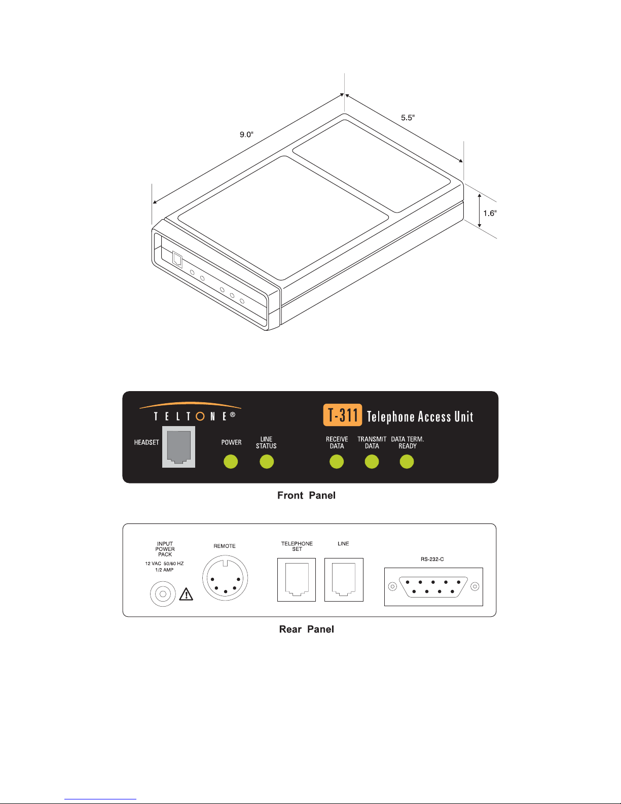
Figure 1 T-311 Telephone Access Unit. . . . . . . . . . . . . . . . . . . . . . . . . . . . . . . . . 2
Telephone Line Control Features . . . . . . . . . . . . . . . . . . . . . . . . . . . . . . . . . . . . . 3
Communication Features . . . . . . . . . . . . . . . . . . . . . . . . . . . . . . . . . . . . . . . . . . . 3
Outgoing Call Features . . . . . . . . . . . . . . . . . . . . . . . . . . . . . . . . . . . . . . . . . . . . 4
Call Answering Features. . . . . . . . . . . . . . . . . . . . . . . . . . . . . . . . . . . . . . . . . . . . 4
Applications . . . . . . . . . . . . . . . . . . . . . . . . . . . . . . . . . . . . . . . . . . . . . . . . . . . . . 5
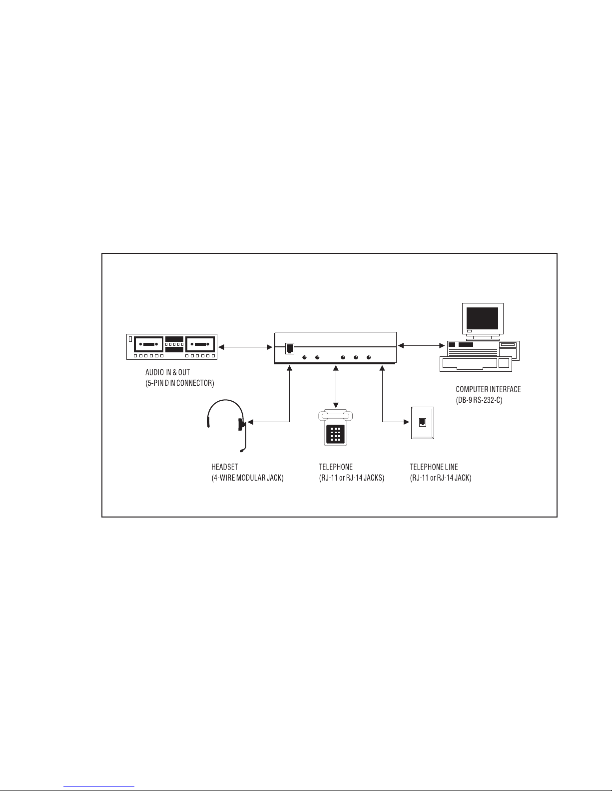
Figure 2 Typical Setup for Outgoing Calls . . . . . . . . . . . . . . . . . . . . . . . . . . . . . . 5
Chapter 2: Operating Modes . . . . . . . . . . . . . . . . . . . . . . . . . . . . . . . . . . . . . . . . . . . . . 7
Ready Mode. . . . . . . . . . . . . . . . . . . . . . . . . . . . . . . . . . . . . . . . . . . . . . . . . . . . . 7
Active Mode . . . . . . . . . . . . . . . . . . . . . . . . . . . . . . . . . . . . . . . . . . . . . . . . . . . . . 7
Table 1 LED Indicators . . . . . . . . . . . . . . . . . . . . . . . . . . . . . . . . . . . . . . . . . . . . . 7
Chapter 3: Installation . . . . . . . . . . . . . . . . . . . . . . . . . . . . . . . . . . . . . . . . . . . . . . . . . . 8
Accessories . . . . . . . . . . . . . . . . . . . . . . . . . . . . . . . . . . . . . . . . . . . . . . . . . . . . . 8
Installation
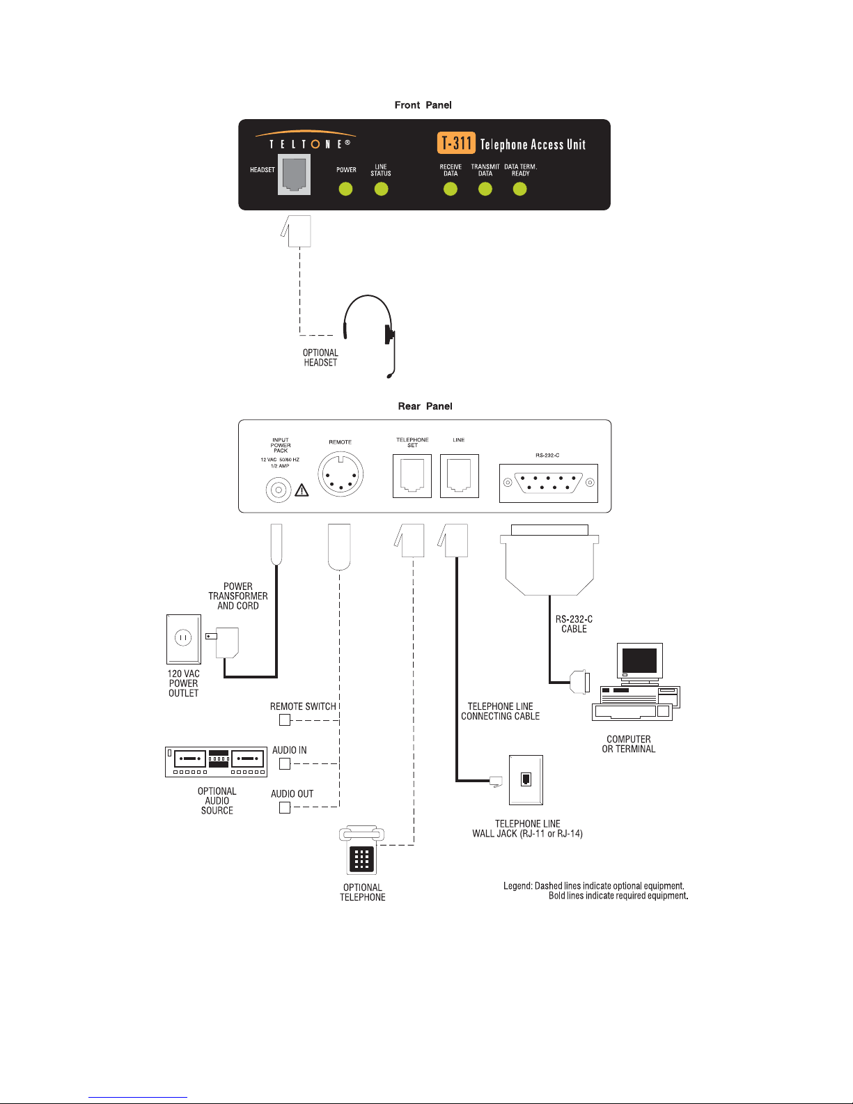
Figure 3 System Connections . . . . . . . . . . . . . . . . . . . . . . . . . . . . . . . . . . . . . . . 9
Table 2 T-311 RS-232-C Interface . . . . . . . . . . . . . . . . . . . . . . . . . . . . . . . . . . . 10
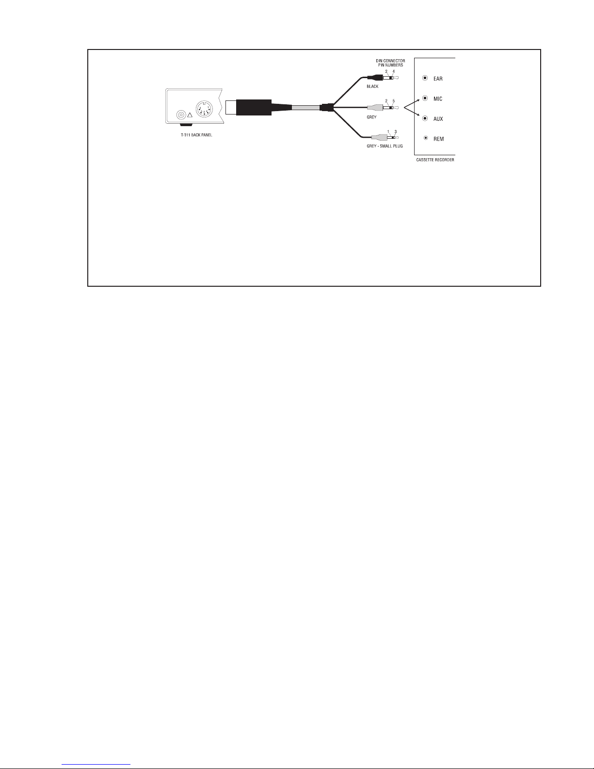
Figure 4 Remote Connector Cable and Pin Functions . . . . . . . . . . . . . . . . . . . 11
Figure 5 Universal Mounting Bracket (Optional). . . . . . . . . . . . . . . . . . . . . . . . . 12
Figure 6 Universal Mounting Shelf (Optional) . . . . . . . . . . . . . . . . . . . . . . . . . . 12
Chapter 4: Dialing Instructions. . . . . . . . . . . . . . . . . . . . . . . . . . . . . . . . . . . . . . . . . . . 13
How to Dial. . . . . . . . . . . . . . . . . . . . . . . . . . . . . . . . . . . . . . . . . . . . . . . . . . . . . 13
Sending DTMF Digits . . . . . . . . . . . . . . . . . . . . . . . . . . . . . . . . . . . . . . . . . . . . . 13
Chapter 5: Answering Calls . . . . . . . . . . . . . . . . . . . . . . . . . . . . . . . . . . . . . . . . . . . . . 15
Ringing Detection . . . . . . . . . . . . . . . . . . . . . . . . . . . . . . . . . . . . . . . . . . . . . . . 15
Auto Answer . . . . . . . . . . . . . . . . . . . . . . . . . . . . . . . . . . . . . . . . . . . . . . . . . . . . 15
Security Checking. . . . . . . . . . . . . . . . . . . . . . . . . . . . . . . . . . . . . . . . . . . . . . . . 16
Transferring Calls . . . . . . . . . . . . . . . . . . . . . . . . . . . . . . . . . . . . . . . . . . . . . . . . 16
Chapter 6: Calling the T-311 . . . . . . . . . . . . . . . . . . . . . . . . . . . . . . . . . . . . . . . . . . . . 17
Table 3 Audible Prompts. . . . . . . . . . . . . . . . . . . . . . . . . . . . . . . . . . . . . . . . . . . 17
Chapter 7: Record & Play Back Messages . . . . . . . . . . . . . . . . . . . . . . . . . . . . . . . . . 19
. . . . . . . . . . . . . . . . . . . . . . . . . . . . . . . . . . . . . . . . . . . . . . . . . . . . . . 8
Connecting the T-311 to the Recording Device . . . . . . . . . . . . . . . . . . . . . . . . . 19
Recording from the Line. . . . . . . . . . . . . . . . . . . . . . . . . . . . . . . . . . . . . . . . . . . 19
40-400-00045, Rev. B Pagei
Page 4

T-311
Playing Back to the Line. . . . . . . . . . . . . . . . . . . . . . . . . . . . . . . . . . . . . . . . . . . 19
Chapter 8: Commands. . . . . . . . . . . . . . . . . . . . . . . . . . . . . . . . . . . . . . . . . . . . . . . . . 21
Command Format. . . . . . . . . . . . . . . . . . . . . . . . . . . . . . . . . . . . . . . . . . . . . . . . 21
Table 4 Command Set (Sheet 1 of 2) . . . . . . . . . . . . . . . . . . . . . . . . . . . . . . . . 22
Table 4 Command Set (Sheet 2 of 2) . . . . . . . . . . . . . . . . . . . . . . . . . . . . . . . . 23
Command Descriptions . . . . . . . . . . . . . . . . . . . . . . . . . . . . . . . . . . . . . . . . . . . 24
Digits/Characters for dialing . . . . . . . . . . . . . . . . . . . . . . . . . . . . . . . . . . . . . . . . 24
Modifiers (arguments). . . . . . . . . . . . . . . . . . . . . . . . . . . . . . . . . . . . . . . . . . . . . 24
V Verbose Mode . . . . . . . . . . . . . . . . . . . . . . . . . . . . . . . . . . . . . . . . . . . . . . . . 28
X Call Progress Monitoring . . . . . . . . . . . . . . . . . . . . . . . . . . . . . . . . . . . . . . . . 28
Detector toggles . . . . . . . . . . . . . . . . . . . . . . . . . . . . . . . . . . . . . . . . . . . . . . . . . 29
S Registers. . . . . . . . . . . . . . . . . . . . . . . . . . . . . . . . . . . . . . . . . . . . . . . . . . . . . 31
Table 5 S Register Summary . . . . . . . . . . . . . . . . . . . . . . . . . . . . . . . . . . . . . . . 32
Chapter 9: Messages. . . . . . . . . . . . . . . . . . . . . . . . . . . . . . . . . . . . . . . . . . . . . . . . . . 38
Message Format. . . . . . . . . . . . . . . . . . . . . . . . . . . . . . . . . . . . . . . . . . . . . . . . . 38
Table 6 T-311 Response Messages. . . . . . . . . . . . . . . . . . . . . . . . . . . . . . . . . . 38
Chapter 10: Configuration . . . . . . . . . . . . . . . . . . . . . . . . . . . . . . . . . . . . . . . . . . . . . . 40
Command Format. . . . . . . . . . . . . . . . . . . . . . . . . . . . . . . . . . . . . . . . . . . . . . . . 40
Saving a Configuration. . . . . . . . . . . . . . . . . . . . . . . . . . . . . . . . . . . . . . . . . . . . 41
S Register Queries and Commands. . . . . . . . . . . . . . . . . . . . . . . . . . . . . . . . . . 41
Table 7 Configuration Options . . . . . . . . . . . . . . . . . . . . . . . . . . . . . . . . . . . . . . 42
Table 8 Default Configuration (by Parameter). . . . . . . . . . . . . . . . . . . . . . . . . . . 42
Table 9 Default Configuration (by Code). . . . . . . . . . . . . . . . . . . . . . . . . . . . . . . 43
RS-232-C Communications Link . . . . . . . . . . . . . . . . . . . . . . . . . . . . . . . . . . . . 43
Table 10 DTMF/ASCII/DTMF Translation . . . . . . . . . . . . . . . . . . . . . . . . . . . . . . 44
Appendix A: Service Information. . . . . . . . . . . . . . . . . . . . . . . . . . . . . . . . . . . . . . . . . . 46
Ordering Information. . . . . . . . . . . . . . . . . . . . . . . . . . . . . . . . . . . . . . . . . . . . . . 46
Warranty. . . . . . . . . . . . . . . . . . . . . . . . . . . . . . . . . . . . . . . . . . . . . . . . . . . . . . . 46
Troubleshooting . . . . . . . . . . . . . . . . . . . . . . . . . . . . . . . . . . . . . . . . . . . . . . . . . 47
Return for Repair Procedure . . . . . . . . . . . . . . . . . . . . . . . . . . . . . . . . . . . . . . . 47
Appendix B: Specifications . . . . . . . . . . . . . . . . . . . . . . . . . . . . . . . . . . . . . . . . . . . . . 48
Figure 7 T-311 Block Diagram. . . . . . . . . . . . . . . . . . . . . . . . . . . . . . . . . . . . . . 50
Appendix C: Reading and Writing to Bit-Mapped S Registers. . . . . . . . . . . . . . . . . . . 51
Appendix D: ASCII Characters & DTMF Frequencies. . . . . . . . . . . . . . . . . . . . . . . . . 52
Table 11 T-311 ASCII Character Set . . . . . . . . . . . . . . . . . . . . . . . . . . . . . . . . . 52
Table 12 DTMF Frequencies . . . . . . . . . . . . . . . . . . . . . . . . . . . . . . . . . . . . . . . 53
Appendix E: Glossary . . . . . . . . . . . . . . . . . . . . . . . . . . . . . . . . . . . . . . . . . . . . . . . . . 54
Index . . . . . . . . . . . . . . . . . . . . . . . . . . . . . . . . . . . . . . . . . . . . . . . . . . . . . . . . . . . . . .55
Page ii
Page 5

Reference Manual Contents
U.S. Regulatory Compliance
FCC Part 68 Notice: To comply with FCC Part 68 regulations, the following requirements must be met:
1. If the telephone company requests information on the equipment connected to their lines, please tell them:
a. the telephone number the equipment is connected to;
b. this equipment operates on standard RJ11 phone jacks;
c. the FCC registration number;
d. the ringer equivalence number (REN). The REN shows how many devices, such as phones, modems, etc. can be
connected to your line. In most areas, there cannot be more than five devices (i.e., a REN of five) on a phone line.
If the REN is exceeded, then your phone may not ring properly.
NOTE: Items C and D above are found on the label on any Teltone equipment connected to your telephone line.
2. These devices must not be installed on coin-operated telephone lines or party lines.
3. Repair work on this device must be done by Teltone Corporation.
4. If any trouble is experienced with this equipment, the telephone company may request that the customer disconnect
the registered equipment from the telephone line to determine if the registered equipment is malfunctioning and if the
registered equipment is malfunctioning, the use of such equipment shall be discontinued until the problem has been
corrected.
FCC Part 15 Class A Notice: This equipment has been tested and found to comply with the limits for a Class A digital
device, pursuant to part 15 of the FCC Rules. These limits are designed to provide reasonable protection against harmful
interference when the equipment is operated in a commercial environment. This equipment generates, uses, and can
radiate radio frequency energy and, if not installed and used in accordance with the instruction manual, may cause
harmful interference to radio communications. Operation of this equipment in a residential area is likely to cause harmful
interference in which case the user will be required to correct the interference at his own expense.
Canadian Regulatory Compliance
Notice: This equipment meets the applicable Industry Canada Terminal Equipment Technical Specifications. This is
confirmed by the registration number. The Industry Canada label or the abbreviation, IC, before the registration number
signifies that registration was performed based on a Declaration of Conformity indicating that Industry Canada technical
specifications were met. It does not imply that Industry Canada approved the equipment. Industry Canada does not
guarantee the equipment will operate to the user's satisfaction. Before installing this equipment, users should ensure that
it is permissible to connect it to the facilities of the local telecommunications company. The equipment must also be
installed using an acceptable method of connection. In some cases, the company’s inside wiring associated with a single
line individual service may be extended by means of a certified connector assembly (telephone extension cord). The
customer should be aware that compliance with the above conditions may not prevent degradation of service in some
situations.
Repairs to certified equipment should be made by Teltone Corporation. Any repairs or alterations made by the user to this
equipment, or equipment malfunctions, may give the telecommunications company cause to request the user to
disconnect the equipment. Users should ensure for their own protection that the electrical ground connections of the
power utility, telephone lines, and internal metallic water pipe system, if present, are connected together. This precaution
may be particularly important in rural areas.
Caution: Users should not attempt to make such connections themselves, but should contact the appropriate electric
inspection authority, or electrician, as appropriate. The Ringer Equivalence Number (REN) assigned to each terminal
device provides an indication of the maximum number of terminal devices to be connected to a telephone interface
without overloading the interface. The termination on an interface may consist of any combination of devices subject only
to the requirement that the sum of the REN of all devices does not exceed five (5) in most, but not all cases. Check with
your local exchange carrier for the REN limit in your service area. The REN assigned to each device is located on the
equipment label.
COMPLIANCE NOTICE: This digital apparatus does not exceed the Class A limits for Radio Noise Emissions set out in
the equipment standard ICES-003 for digital apparatus.
AVIS DE CONFORMATION: Le présent appareil numérique n’émet pas de bruits radioélectriques dépassant les limites
applicables aux appareils numériques de la class A prescrites dans le Règlement sur le brouillage radioélectriques édicté
par le ministère des Communications du Canada.
40-400-00045, Rev. B Page iii
Page 6

T-311
IMPORTANT SAFETY INSTRUCTIONS
When using this product, basic safety precautions, including the following, should always be followed to reduce
the risk of fire, electric shock, and injury to persons.
1. Read and understand all instructions.
2. Follow all warnings and instructions marked on the product.
3. The product should be operated only from the type of power source indicated on the marking label. If you
are not sure of the type of power supply, consult your dealer or local power company. The product is
designed for indoor use only.
4. To reduce the risk of electric shock, do not disassemble the product, but take it to qualified service
personnel when service or repair work is required. Opening or removing covers may expose you to
dangerous voltages or other risks. Incorrect reassembly can cause electric shock when the appliance is
subsequently used.
5. If the product does not operate normally by following the operating instructions, or if the product has been
dropped or the cabinet has been damaged, or if the product exhibits a distinct change in performance, refer
servicing to qualified service personnel.
6. If the product is used in a manner other than specified in this manual, the protection provided by the product
may be impaired.
7. For the purpose of removing power from the product, the power input connector is the main power
disconnect point. Pull the power cord away from the connector to ensure power disconnect.
8. Adequate air flow must be maintained in order for the product to operate correctly. Do not wrap the product
in blankets, paper, or other material that may impede ventilation.
Page iv
Page 7

Reference Manual Contents
Recording of Two-way Telephone Conversations
This product may be used to record telephone conversations.Use in this application is subject to reg
ulations adopted by the Federal Communications Commission, and is additionally subject to local
state tariffs. Check with your local service provider to verify if any special regulations apply.
To comply with FCC regulations, this product is equipped so that it can be connected or disconnected
at the will of the customer.In addition, one of the following conditions must apply:
All parties to the telephone conversation must give their consent to the recording of the conversation,
and the prior consent must be obtained in writing or be part of, and obtained at the start of, the re
cording, or
All parties to the telephone conversation must be verbally notified at the beginning of the conversation
and the notification must be recorded as part of the call, by the recording party, or
A distinctive recorder tone, repeated at intervals of approximately fifteen seconds, is required to alert
all parties when the recording equipment is in use. The distinctive recording tone can be provided as
part of (1) the recording equipment, or (2) registered or grandfathered protective circuitry.
Note:
Recorder tone is not supplied by the T-311.
-
-
40-400-00045, Rev. B Pagev
Page 8

T-311
This page intentionally left blank.
Page vi
Page 9

Reference Manual Chapter 1: Introduction
Chapter 1: Introduction
With the Teltone T-311 Telephone Access Unit computers can make and answer telephone calls, and
information about those calls can be returned to the computer.While a modem only transmits data
from computer to computer over telephone lines, the T-311 allows communication between called and
calling parties.
This communication is made possible by the conversion of DTMF-to-ASCII and ASCII-to-DTMF.With
the T-311, computers and other terminal devices can control telephone system functions such as an
swering and placing calls, observing call status, sending or receiving DTMF signals, “flashing”the
line, and coupling audio sources, like speech synthesizers, onto the line.
For compatibility with communications software, the T-311 uses the industry-standard AT command
set. It responds to commands and call processing events by sending messages to the computer.
-
When used in conjunction with contact management software, the T-311 is a powerful automatic di
aler.Working with the records from the software database, it speeds call completion by detecting
busy/reorder tone and immediately moving to the next number.The result is increased “talk time”,
thereby improving the efficiency of calling agents.
-
Using This Manual
This manual is intended to assist developers with tailoring the T-311 to work with a software program.
Some of the steps in the manual are not required for every application and are marked: (Optional).
Complete the optional steps if needed for your application.
Manual Revisions
The information in this manual addresses T-311-B-01 units produced after October 3, 1994 . The production date is stamped on the bottom of each T-311 unit. All information related to Caller ID and
Visual Message Waiting are features of the T-311-B-01 ONLY.The T-311-C-01 replaces the
T-311-A-01 and is functionally the same.
40-400-00045, Rev. B Page1
Page 10
T-311
Page 2
Figure 1 T-311 Telephone Access Unit
Page 11

Reference Manual Chapter 1: Introduction
Telephone Line Control Features
Off-hook
The T-311 takes the line off-hook (“seizes” the line) when commanded by the computer to make or an
swer a call.The T-311 uses the standard ATD command to dial outgoing calls, but unlike most
modems it provides full call progress monitoring.
On-hook
The T-311 places the line on-hook (disconnects) upon command from the computer, or automatically
if a caller fails the security check, loop current is lost, or inactivity timeout occurs.
Ringing
The T-311 detects ringing on its incoming line. If response messages are enabled, the T-311 sends a
RING message to the computer.The call is automatically answered if Autoanswer is enabled.
Hold
The T-311 puts calls on hold and removes the hold when commanded by the computer.
Communication Features
-
DTMF/ASCII Conversion
After a telephone connection has been established, ASCII characters from the computer are converted to DTMF tones and forwarded to the network.In the opposite direction, DTMF digits entered at
a telephone keypad are converted to ASCII characters and forwarded to the computer.
FSKDecoding (Caller ID andVMWI) -- Only Applies to M-311-B-01 Units
The central office (telephone company) sends the FSK signals (Caller ID), after the first ring and before the second ring.Caller ID information, in single message format and multiple message format,
are decoded and converted to ASCII characters to be transmitted via the RS232C port. Visual
Message Waiting Indication signals are sent during on-hook idle times.These FSK messages are decoded and sent out via RS232C along with a visual indication on the front panel of the T-311, to
inform the user of messages waiting in their mailbox.
Electronic Voice
By controlling an audio source such as a recorded tape player or speech synthesizer, the computer
can use the T-311 to send messages to the called party, or record messages received over the phone
line.
Headset Interface
When used with a headset, the T-311 becomes a powerful and efficient “computerized telephone” for
telemarketing and similar applications, relieving the user of most of the mechanics of setting up, dial
ing, and disconnecting calls.
-
The headset should meet the following requirements:
•
UL and CSA approval
•
Electret-type microphone (typically battery or AC powered)
•
external amplifier with volume control
•
modular four-wire connector (plugs into front of T-311).
Note:
40-400-00045, Rev. B Page3
Headsets with telephone-like features duplicate some of the functions of the T-311 and may
require additional programming.
Page 12

T-311
Telephone Interface
A telephone connected to the T-311 can be used two ways:(1) as an auxiliary telephone sharing the
line with the T-311 (outgoing calls are dialed from the telephone set directly over the telephone and do
not go through the T-311 circuitry), or (2) operating through the T-311 (outgoing calls are dialed from
the computer). The second mode is identical to operation with a headset.
Standard Commands
The industry-standard AT command set is used where applicable.
Selectable Baud Rates
You can select a baud rate from 300 to 9600 bps to set the speed with which ASCII data is transferred
between the computer and T-311. It does not refer to the rate of data transmittal across the telephone
lines.See Chapter 10, “RS-232-C Communications Link” on page 43 for details.
Outgoing Call Features
Autodialing
The T-311 can autodial a series of programmed numbers.It can also permanently store a number
string for repeated dialing with the command “ATDS”. (See page 26 for more detail.)
Tone and Pulse Dialing
To ensure the widest possible range of applications, the T-311 works with both DTMF and rotary signaling.
Dial Tone Detection
The T-311 can detect both primary and secondary dial tones.In the autodialing mode, the T-311 can
be programmed to delay dialing until it detects secondary dial tone.
Call Progress
By detecting and analyzing standard call progress tones (e.g., reorder, busy, and audible ringing
/“ringback”), the T-311 is able to return information to the computer about the status of originated
calls.By detecting Special Information Tones (S.I.T.), the T-311 recognizes incomplete calls to speed
placement of the next call.
Call Answering Features
Auto and Forced Answer
Auto answer allows unsupervised operation of the T-311; forced answer commands the T-311 to an
swer the call.By disabling answer altogether, the T-311 owner can ensure that the telephone line is
used for making outgoing calls only.
Security Checking on Incoming Calls
When security is enabled, the T-311 automatically disconnects callers who fail to enter the correct
password in the allotted time.
-
LED Indicators
The T-311 includes five LEDs.Operation of the LEDs is described in Table 1.
Page 4
Page 13
Reference Manual Chapter 1: Introduction
Modular Connectors
For ease of installation and to promote the widest possible range of applications, all T-311 connectors
are standard and modular.
Nonvolatile Memory
The T-311 uses EEPROM memory to store configuration data.
Applications
The T-311 is a device marketed and intended for use in commercial, industrial, and business environ
ments.
Applications for the T-311 fall into three basic categories:(1) Outgoing calls, (2) Incoming calls, and
(3) Security for incoming calls.
T-311
-
Outgoing Calls
This is the most sophisticated application for the T-311, particularly when incorporation of the proper
applications software and an audio source allow the T-311 to operate without human supervision. Fig
ure 2 shows an equipment configuration for outgoing call applications.Examples include:
(1) Telemarketing
(2) Autodialing with software, autodialing from a list of numbers
(3) Automatic remote monitoring of equipment
(4) Automatic outbound messaging
(5) Customer service surveys
(6) Appointment verification
(7) Collections on receivables
(8) Purchasing applications to solicit multiple bids.
40-400-00045, Rev. B Page5
Figure 2 Typical Setup for Outgoing Calls
-
Page 14

T-311
Incoming Calls
In this type of application, the caller uses the T-311 to update or verify information in a remote com
puter database.Examples include:
(1) Message forwarding systems
(2) Financial transaction systems
(3) Alarm systems
(4) Energy management systems
(5) Credit card verification systems
(6) Mail order systems.
(7) Smal Business
-
Inward Security
The T-311’s security checking feature can be used for incoming call applications like Dialback security
systems or Building security systems.
Page 6
Page 15

Reference Manual Chapter 2: Operating Modes
Chapter 2: Operating Modes
Ready Mode
The T-311 enters the ready mode when: power is applied, a reset is performed using the Z command,
or the DTR signal from the computer is reasserted (if that option is enabled with the &D2 command).
In this mode, the T-311 is disconnected from the telephone line.While in the ready mode, the T-311
monitors the line for ringing voltage, which announces an incoming call, FSK transmissions (Caller ID)
information and for loop current, which reveals the switchhook status of the auxiliary telephone.The
T-311 also monitors the computer for changes in DTR and the command “AT”. Commands are pro
cessed and messages returned to the computer.
Active Mode
The T-311 enters the active mode when the line is seized.The T-311 returns to the ready mode if:dial
tone is not found when making a call, a no-answer is detected, or the caller fails the security check.
Otherwise, the T-311 remains in the active mode until:loop current is lost, the line is disconnected by
the H command, or no-activity timeout occurs.In the active mode, the T-311 processes commands,
converts DTMF to ASCII and vice versa, couples audio input onto the line, monitors for loop current,
and maintains the no-activity timer.
Active Mode Response to COD
The T-311 responds to cut-off on disconnect (COD or forced disconnect) by going on-hook.You can
disable COD with the S*2 register on page 36.
-
LED Indicators
Table 1 LED Indicators
Indicator Color State Description
Power ON Green ON Power is applied to the T-311
Line Status
Red
Receive Data Red ON Data is being received by the computer
Transmit Data Red ON Data is being sent by the computer
Data Terminal
Ready (DTR)
Red ON
Note 1: Visual Message Waiting transmission has been received.
ON
(steady)
Slow flash On/Off, Call on hold
Fast flash Rapid blinking on Incoming call (ringing)
OFF Idle
Flash Two blinks on, 2 seconds off (repeated) VMW (note 1)
Line off-hook
computer is ready to receive data, or DTR is ignored by the
computer (see “Response to DTR” command, page 34).
40-400-00045, Rev. B Page7
Page 16

T-311
Chapter 3: Installation
CAUTION:
(1) Never install telephone wiring during a lightning storm.
(2) Never install telephone jacks in wet locations unless the jack is specifically designed for wet
locations.
(3) Never touch uninsulated telephone wires or terminals unless the telephone line has been
disconnected at the network interface.
(4) Use caution when installing or modifying telephone lines.
This chapter provides a list of required accessories and information about installing the T-311. Infor
mation about compliance with FCC and DOC requirements and T-311 regulatory is listed at the front
of the manual.
-
Accessories
As shown in Figure 3, the T-311 must be connected to a telephone line, a computer, and a standard
120-volt AC outlet to a power transformer.
Connections to an auxiliary telephone, headset, and audio source are optional. Accessories required
to make these connections include:
(1) A plug-in transformer (Included with unit, P/N 610-00066-01.)
(2) A standard 6-position modular telephone cord. (Available as an ordering option, see page 46.)
(3) A cable to connect the T-311’s DCE interface to the RS-232-C port of the computer. The cable
should terminate on its T-311 end in a male DB-9 connector and supply the signals listed in Table 2.
(A DB-9 to -25 adapter cable, P/N 742-00017-01, is available as an ordering option.)
(4) Remote cable (Optional): If an audio source and/or remote control switch is used, a cable is
required to connect them to the T-311. (Not supplied.) The cable should terminate on its T-311 end in
a 1/2-inch diameter 5-pin DIN connector with pins at 180 degrees to the key and 3 plugs at the other
end (typical of small portable tape recorder cables). The cable connections and pin functions for the
remote interface are given in Figure 4.
(5) Wall Mounting Bracket (Optional): For wall mounting up to four T-311 units, UM-111-401 bracket
(see Figure 5) is available as an ordering option. For wall mounting up to eight units, UM-113-801
(Figure 6) is available as an ordering option.
Installation
Step 1: Connect Telephone Line
•
Plug one end of the modular telephone line connecting cable into the jack labeled “Line” on the
back of the T-311.
•
Plug the other end of the cable into the telephone line wall jack.
Page 8
Page 17
Reference Manual Chapter 4: Dialing Instructions
40-400-00045, Rev. B Page 9
Figure 3 System Connections
Page 18

T-311
Table 2 T-311 RS-232-C Interface
Pin number Description Source
1
2
3
4
5
6
7
8
9
Data carrier detect ()
Receive data ()
Transmit Data (TX)
Data terminal ready ()
Signal Ground (SG)
Data set ready ()
Request to send (RTS)
Clear to send ()
Ring indicator (RI)
T-311
T-311
Computer
Computer
Computer
T-311
Computer
T-311
T-311
Step 2: Connect Computer
Refer to the table above to check the RS-232-C interface.
•
Plug the male DB-9 connector end of the RS-232-C cable into the T-311 jack labeled “RS-232-C”.
•
Plug the other end of the cable into the RS-232-C connector on the computer.
•
Step 3: (Optional) Connect Telephone
• Connect the telephone to the T-311 jack labeled “Telephone Set” using the modular cord supplied
with your telephone set.
Step 4: (Optional) Connect Headset
• Connect the headset to the T-311 front panel jack labeled “Headset”.
Step 5: (Optional) Connect Remote Equipment
• The T-311 jack labeled “Remote” may be used to monitor or record information from the telephone
line. It may also be used to play back to the telephone line the output from a recorder or some
other audio source. This interface uses a 5-pin DIN connector with the pin assignments identified
in Figure 4. (See Chapter 7 for more information.)
Step 6: Enable Computer/T-311 Communications
•
Configure the computer to communicate at 1200 baud, using a ten-bit word: one start bit, eight
data bits, parity off, and one stop bit.
•
Enable the communication software which allows the computer to communicate via its RS-232-C
port.
Step 7: Connect Power Transformer
•
Plug the cable end of the power transformer into the T-311 connector labeled “Power”.
•
Plug the transformer end into a 120-volt AC power outlet.
•
Watch for the green POWER LED on the T-311 front panel to light. The red LED will also turn on
if either (1) the computer is on, or (2) the T-311 is configured to ignore DTR (“&D” command, see
Chapter 8).
•
Watch for a message like the following: "T311 TAU 2.00 COPYRIGHT 1991-94 TELTONE CORP.”
Step 8: Verify Configuration
•
From the communication software, send an AT command to the T-311.
Page 10
Page 19
Reference Manual Index
INPUT
REMOTE
POWER
PACK
12 VAC 50/60 HZ
1/2 AMP
!
Pin No. Function
1 and 3
2
4
5
Isolated, low-voltage switch turns recoder on/off. Use with recorder’s
"Remote" input. It must not be used to switch AC power for the recorder
or other device.
Common ground for audio input and output signals.
Audio signal from recorder to phone line.
Audio signal to recorder from phone line.
Figure 4 Remote Connector Cable and Pin Functions
• If everything is configured correctly, the T-311 will respond with “OK”.
-or-
• If “OK” was not returned, the default configuration of the T-311 may not be compatible with your
setup. See Chapter 10.
Step 9: (optional) Change defaults
• If any factory default options require changing, configure the T-311 as described in Chapter 10.
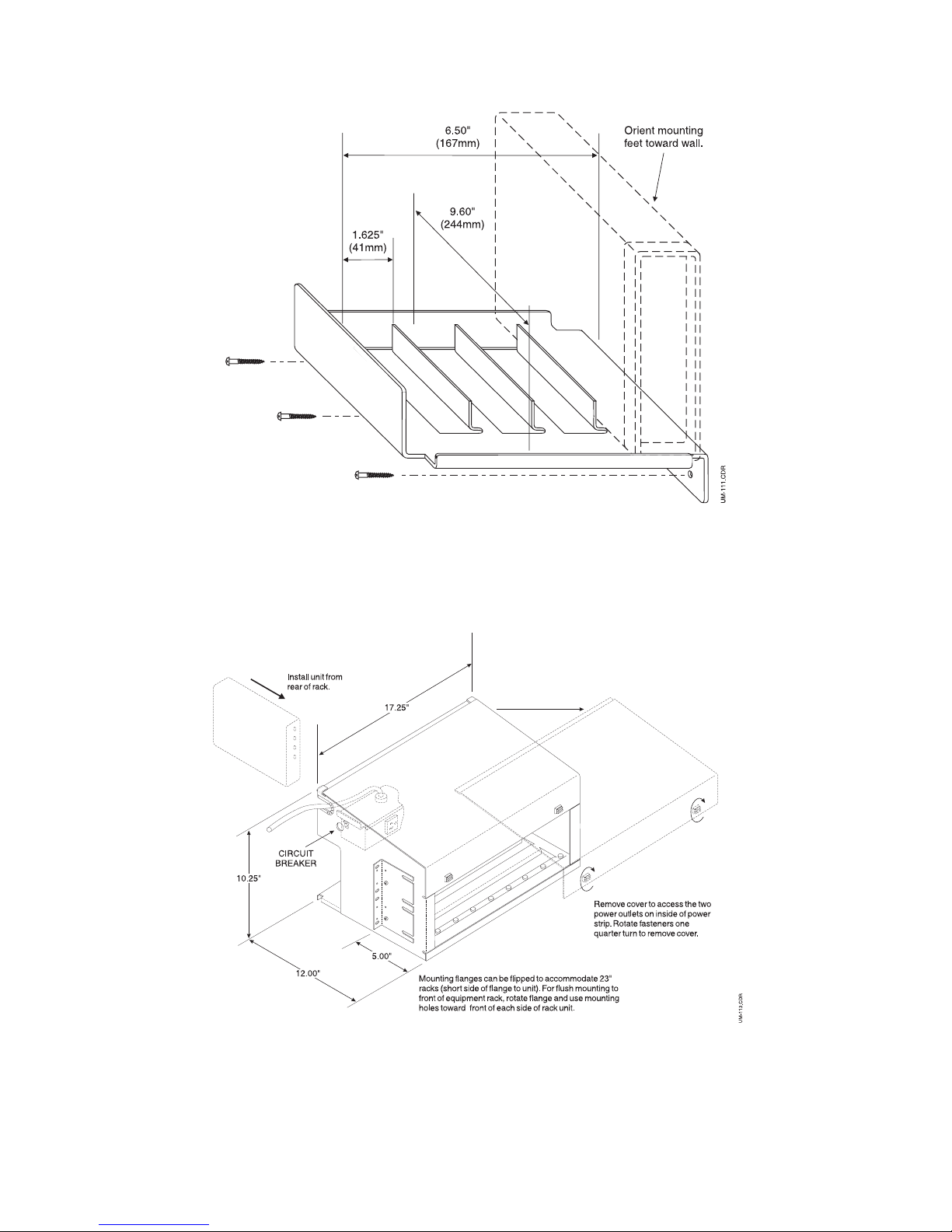
Step 10: (optional) Mount the T-311
If you have ordered the mounting bracket (model UM-111-401), install the T-311 as follows.
•
Use the three screws to install the bracket to a 3/4-inch-thick wood panel that is attached to a wall.
•
If you are installing multiple units, insert the first T-311 in the slot closest to the wall. (The bottom
of each unit should face the wall.)
-or-
If you have ordered the mounting bracket (UM-113-801), install the T-311 as instructed in the steps
below.Please note that there is space for eight transformers; six in the back of the shelf and two in the
front. The shelf includes an eight outlet power strip with a 14-foot cord.
•
When you remove the shelf from the box, rotate the fasteners on the front and remove the cover.
Untie the power cord and run it through the slots at the back of the shelf.
•
Insert the units in the shelf so that you can see the LEDs through the front of the shelf. (The space
at the back of the shelf provides room to attach cabling to each device.)
•
Using the mounting hardware supplied with the carrier, install it in center or front mount positions
in a 19- or 23-inch rack.
40-400-00045, Rev. B Page11
Page 20
T-311
Figure 5 Universal Mounting Bracket (Optional)
Figure 6 Universal Mounting Shelf (Optional)
Page 12
Page 21

Reference Manual Chapter 4: Dialing Instructions
Chapter 4: Dialing Instructions
This chapter explains how to place a call and how to dial a remote device through the T-311.
How to Dial
The T-311 allows calls to be placed by the computer operator or by software controlling the computer.
If a W is embedded in the dialed number string, the T-311 monitors the line for dial tone (both primary
and secondary), dials the digits in the specified manner (tone or pulse), and performs whatever oper
ations are enabled by the X command.
For example:ATD4871515 causes the computer to tell the T-311 to go off-hook and dial the number
487-1515.
Step 1: Issue D Command
Enter “ATD” followed by the telephone number and a carriage return.
•
The T-311 default dialing mode is DTMF, but you can specify pulse dialing by entering a P in the
•
dialing string (see Chapter 8, D Command), and return to tone dialing by entering T. (Other dial
modifiers can be embedded in the dialing string as described in Chapter 8.) Note the following ex
amples:
-
-
ATD5551234<CR> Dials the number 555-1234.
ATDP9WT12065551234<CR> Pulse-dials a 9, often required to access an outside line from inside
a PBX. There follows a wait for secondary dial tone, and then the remainder of the number is
tone-dialed: 1-(206)555-1234.
Step 2: Observe Call Progress
• After dialing is complete, the T-311 monitors the line for indications of call disposition. If a
no-answer condition is detected, the T-311 abandons the call and returns to the ready mode. Otherwise, it remains in the active mode until disconnected.
To improve detection of call progress tones, mute the headset microphone by adding L0 to the
end of the dialing string (e.g., ATDT4871515L0). The microphone will be automatically unmuted
when a “VOICE” or “RB LOST” is validated.
Step 3: Disconnect Line
•
When the call is complete, “hang up” by issuing the H command. After executing this command,
the T-311 leaves the active mode and returns to the ready mode.
Sending DTMF Digits
After a connection has been established, either by dialing or answering a call, you may need to send
DTMF digits from the T-311 to use voice mail systems or entering personal identification numbers
(PINs). DTMF digits are sent by issuing another D command in the same format as that used when
setting up the call: ATDn...n<CR> (where n...n is one or more DTMF digits). Alphabetical characters
may be entered by enclosing them in quotation marks, as follows:ATD“n...n”<CR>
The T-311 will convert any characters within quotation marks to DTMF digits so that the caller does
not need to refer to a telephone keypad to determine which digits to send.The conversion is as fol
lows:
ABC = 2
DEF = 3
GHI = 4
JKL = 5
40-400-00045, Rev. B Page13
-
Page 22

T-311
MNO = 6
PQRS = 7
TUV = 8
WXYZ = 9
For example, the command attend “teltone”<CR> will send the digits 8358663.
The entire string, including ATD and both quotation marks, can be up to 40 characters. If more char
acters are to be sent, multiple D commands must be issued.
Once a call has been connected, any subsequent D commands (that is, those entered while the line
is off-hook), are processed in exactly the same manner as the initial D command, except that the
T-311 does not wait 2 seconds for dial tone.
Step 1: Send One or More D commands.
Once a call is established, send DTMF digits or alphabetical characters as follows:
•
Send DTMF digits 1 through 0, A, B, C, D, #, or * by issuing the command
•
ATD n...n <CR>
Send alphabetical characters with the command
ATD“ n...n” <CR>
Step 2: Disconnect Line
• When data transmission is complete, “hang up” by issuing
ATH<CR>
-
Page 14
Page 23

Reference Manual Chapter 5: Answering Calls
Chapter 5: Answering Calls
This chapter explains how to answer calls coming in to the T-311. Messages shown in this chapter are
sent only if the T-311 is in V3 mode. (See page 28 for more detail.)
Ringing Detection
Telephone Rings
The T-311 is enabled to detect ringing voltage when the line is not seized by either the T-311 or a tele
phone sharing the line with the T-311. As each burst of ringing voltage is detected, the T-311 transmits
the message: RING
FSK Transmission Decode
After the first ring, while on-hook, the T-311 will decode a 1200 baud FSK message used to transmit
Caller ID. This Caller ID message may be sent in either single message format (date/time/and num
ber) or multiple message format (date/time, number and name).
Idle Operation
The T-311 will look for a FSK transmission while on-hook as long as ringing is not in progress.During
idle periods, the T-311 will look for the VISUAL MESSAGE WAITING information in either single or
multiple message format.This signal is used to inform the user that a message is waiting to be picked
up at the Central Office voice mail location.
-
-
Auto or Forced Answer
If auto or forced answer occurs, the T-311 enforces two seconds of line silence as a billing delay, signals the caller with a burst of connection tone, and transmits the message:ANSWERED
Auto Hang Up Incoming Calls
After an incoming caller has hung up, the T-311 waits for five seconds of dialtone, four cycles of busy
tone or reorder tone, and hangs up to prepare for the next call.(The hang up on dial tone can be disabled if Bit 6 of the S14 register is set to 1.)
Abandoned Call
If the caller abandons the call before answer occurs, the T-311 transmits the message: RING LOST
Auto Answer
The T-311 can answer calls automatically when the S0 register is set to a value other than 0.Auto an
swer occurs when the count of incoming rings equals the value set in the S0 register.(See page 32
for more information on the S0 register.)
To change current setting: Issue the command ATS0=xx <CR> replacing xx with the desired number
of rings.
To disable auto answer: Issue the command: ATS0=0 <CR>
Forced Answer
Forced answer allows calls to be answered manually regardless of the S0 register settings.The com
mand to execute forced answer is A.
(default)
-
-
To answer a ringing phone: Issue ATA<CR>.
40-400-00045, Rev. B Page15
Page 24

T-311
Security Checking
The T-311 has the capability to provide incoming call security by requiring the caller to enter a
multi-digit DTMF password after the T-311 answers the call and issues a connection tone (941 Hz for
1 second).
Note:
To enable security checking: Issue the command AT*C1<CR>
If you want computer display messages PASS and FAIL in addition to the tones, enter the default set
ting: ATV3<CR>
Note:
The T-311 will always issue the connection tone when the password requirement is enabled
(*C=1) or if Bit 3 of the S*2 register is set to 1. In this situation, if a second T-311 is the caller, that
T-311 will detect the connection tone and issue the message “T-311 CONNECT” (when V is set to
V3) to its computer port.
Security code checking requires that DTMF detection also be enabled.To do this, enter:
ATXB<CR>
is enabled, no caller will be able to access the T-311.
(default)
You must also set a password.If no password is set and security checking
To set the password
Issue the command: AT*Wn...n#<CR>
The T-311 responds to a correct password entry with a single tone and an incorrect entry with three
tones.For more information on how the T-311 handles calls with passwords enabled, see Chapter 6
(Calling the T-311.)
Transferring Calls
A T-311 operating behind a PBX can transfer calls to another PBX station.
Flash the line
A transfer is initiated by “flashing”the line on an established call.To do this, issue the command
ATD!<CR>
-
If the flash is successful, the T-311 returns the message: FLASH
If the flash is unsuccessful (e.g.because an auxiliary telephone sharing the line with the T-311 is
off-hook), the T-311 returns the message (if M is set to M2): FLASH FAILURE and the original con
nection is maintained.
Dial the number
After the line is flashed, dial the other PBX station: ATDn..n<CR>
Disconnect after answer
When the called party answers, hang-up the call with the command: ATH<CR>
-
Page 16
Page 25

Reference Manual Chapter 6: Calling the T-311
Chapter 6: Calling the T-311
This chapter provides instructions for callers using a remote telephone to place calls into a T-311
through a computer.
Table 3, below, explains the three tones you will hear when working with the T-311.
Table 3 Audible Prompts
Name Description Explanation
Connection tone Extended single burst Security disabled: T-311 has answered.
Acknowledgment tone
Error tone Triple burst of DTMF D at on/off rate
Brief single burst of DTMF A for
duration set in S11 register
set in S11 register
Step 1: Dial up the T-311
Dial the telephone number to which the T-311 is connected. Although a pulse-dialing telephone
•
may be used to call the T-311, a DTMF telephone (or a DTMF generator used with a pulse-dialing
telephone) must be used to enter the password (if required) and communicate with the computer
after the connection through the T-311 is established.
Security enabled: T-311 has answered. Enter
password.
Security check has passed.
Security check has failed. T-311 will disconnect.
To call from another T-311, enter ATDn...n<CR> where n...n is the telephone number
Step 2: (Optional) Enter password
• When ringback tone is heard followed by a single burst of connection tone, enter the assigned
password.
n...n# where n...n is the password
Remember to terminate the code with a “#”. You have 4 seconds to enter each digit.
If the correct password is entered in the allotted time, the T-311 responds with a burst of acknowl
edgment tone (see Table 3) and the connection is established. If the password is incorrect, or if
the correct password is not entered in the allotted time, the T-311 responds with three short bursts
of error tone and then disconnects.
Step 3: Communicate with the computer
After the connection is established, DTMF digits you transmit via your telephone keypad are detected
by the T-311 and forwarded to the computer as ASCII characters.
Depending on the application, the computer can be programmed to respond to your input in two ways:
•
By issuing ASCII characters which the T-311 converts to the corresponding DTMF tones and for
wards to you.
•
By controlling an audio source such as a speech synthesizer or recorded tape player, the output of
which the T-311 couples onto the line.
-
-
Step 4: Hang up
When you have completed your call, hang up the telephone.You can program the T-311 to disconnect
automatically in any of the following ways:
40-400-00045, Rev. B Page17
Page 26

T-311
Inactivity Disconnect Timeout will occur if the T-311 does not detect any DTMF digits for the pro
grammed period of time (0 seconds = OFF = Default), the unit will disconnect.To program this timeout
period, see S10 on page 34.
Cut-off On Disconnect will occur if the T-311 detects an open circuit for at least 800 ms.This feature
is always enabled.
Dial Tone/Reorder/Busy Disconnect will occur after five seconds of dial tone
or
four cycles of busy or
reorder tone is detected on an incoming call. To program this feature, see S14, Bit 6 on page 35.The
default for this feature is enabled.
Page 18
Page 27

Reference Manual Chapter 7: Record & Play Back Messages
Chapter 7: Record & Play Back Messages
Notes:
(1) Recording of telephone conversations is subject to FCC regulations. See page 5 for
compliance requirements.
(2) The recorder tone option is not provided by the T-311.
Connecting the T-311 to the Recording Device
A standard cassette player interface cable, with a mating 5-pin DIN connector at one end and three
cable plugs at the other is required (see Figure 5).This cable is connected as follows:
Plug the 5-pin connector into the T-311 connecting jack labeled “Remote”.
•
Connect the black cable plug to the “Earphone” jack on the recording device.
•
Connect the small gray cable plug to the “Remote” jack on the recording device.
•
Connect the larger gray cable plug to the “Aux” jack on the recording device. (If the recording de
•
vice has no “Aux” jack, connect this cable plug to the “Mic” jack.)
Recording from the Line
Step 1: Connect T-311 to Recording Device
• Connect the T-311 to the recording device as described above.
Step 2: Enable Record
• Enable the record function. Typically, this requires pressing both the “Play" and the “Record” buttons on the recording device. (No recording will take place until you establish a call and issue a
“begin recording” command through the T-311 using either of the methods described in Steps 3
and 4 below.)
-
Step 3: Delayed Recording Start:
• Place a call through the T-311 by issuing a “D” command at the computer or through an application program (see Chapter 8 for more information on commands).
•
Start the recording at any time after the connection is established by issuing the command
AT*R1<CR>.
Step 4: Immediate Recording Start
•
If you want to start recording as soon as the call is connected, issue an “H2” command in con
junction with the “D” command. For example: ATH2 D123-4567.
-
Step 5: Stop Recording
•
To stop the recording without terminating the call, issue the command AT*R<CR>. The recording
will be stopped automatically when you use an H command to hang up the line.
Playing Back to the Line
Step 1: Connect T-311 to Recording Device
•
See “Connecting the T-311 to the Recording Device” on page 19.
Note:
If you need to use the “Rewind”or “Fast Forward” functions to position the message, issue an
“H2” command, then rewind or fast forward, then issue an “H”command.
40-400-00045, Rev. B Page19
Page 28

T-311
Step 2: Press Play
Press the “Play” button on the recording device. (The message will not begin playing until you
•
have issued a “Play” command through the T-311 (Step 4).
Step 3: Place Call
Place a call through the T-311 by issuing a “D” command at the computer or through an applica
•
tion program. (Or, on an incoming call, proceed to Step 4.)
Step 4: Start Playing
Start playing the message at any time after the connection is established by issuing the command
•
AT*R2<CR>.
Step 5: Stop Playing
To stop the message without terminating the call, issue the command AT*R<CR>. The recording
•
will be stopped automatically when you use an H command to hang up the line.
-
Page 20
Page 29

Reference Manual Chapter 8: Commands
Chapter 8: Commands
Commands are ASCII character strings sent by the computer to the T-311. They may be issued man
ually—usually, at a keyboard—or automatically through software.For compatibility with existing
communications software, the T-311 uses many of the Hayes AT commands. Some have been modi
fied for use in the T-311 and new commands added to control T-311 features not available in a
modem.
Table 4 summarizes each of the T-311 commands described in this chapter. The commands are listed
in alphabetical order, but can be grouped in five categories, as follows:
-
1. Telephone Commands:
A Answer
D Dial
H Hang up, off-hook, hold
A/ Repeat last command
2. Configuration commands:
E Echo
L Turn microphone on/off
Z Reset
*C Enable/disable passwords
*W Set password nnn
*R Remote equipment control
&F Fetch default
&W Write user configuration (save configuration)
&Z Store phone number
-
3. Status Commands:
I Display product information and version number
*A Display line status (on/off hook, etc.)
*B Display S register status
&D DTR indicator
*D Display last Caller ID message
*E Erase last Caller ID message
4. Remote Equipment Control:
*R or *R0 Turn off both remote switch and remote input to the network
*R1 Turn on remote switch
*R2 Turn on remote switch and the remote audio input
5. Call Progress Detection and Message Display:
Q Message display on/off (Turn on before configuring V, M, or X.)
V Digit code or word messages
M Combination of call progress detection and message display
X Call progress detection on/off
Command Format
All commands, with the exception of REPEAT (A/), are issued in the following format: AT <one or
more commands><CR>
40-400-00045, Rev. B Page21
Page 30

T-311
Table 4 Command Set (Sheet 1 of 2)
Commands flagged with ¶ and all commands preceded by * are unique to the T-311. M commands
(flagged with ¶¶) function differently than the AT M commands.
Command Function
A or A0 Answer ringing line or take line off hold
D Dial a number
E or E0 Disable echo
E1
H or H0
Enable echo
(Default)
Place T-311 on-hook
(Default)
H1 Take T-311 off-hook
H2 Take T-311 off-hook and close remote control relay
H3 Put line on hold (or on-hook when configured for alternate disconnect)
I or I0 Display product code and rev. number
I1 Display checksum
I2 Test the T-311’s internal RAM (perform a soft reset).
L OR L0 Turn microphone off
L1 Turn microphone on
M or M0
Display no call progress response messages
M1¶¶ Display messages until answer (without testing for loop current (call following)
M2¶¶
Display messages until answer (with testing for loop current)
(Default)
N Display the stored telephone number
Q or Q0
Display messages (M and V commands must also be set)
(Default)
Q1 Display no messages
V or V0 Return single digit result codes
V1 Return standard AT word messages
V2 Return two-digit result codes
V3
Return T-311 word messages
(Default)
X or X0 Enable only response codes 0 through 4 (Dial tone and busy signal are not
recognized.)
X1 (not applicable in T-311; command will function as X0)
X2 Enable dial tone detection and response codes 0 through 6
X3 Enable busy signal detection and response codes 0 through 5 and 7
X4 Enable both dial tone and busy signal detection and response codes 0 - 7
X5¶ Toggle on/off dial, busy, ringback, and reorder tones
X6 Toggle on/off the voice detector
X7 Toggle on/off the Special Information Tone (SIT) detectors
X8 Toggle on/off the DTMF detectors
X9 Toggle on/off single tone detection
XB Enable all detectors. All call progress tones are detected and reported. (Default)
Page 22
Page 31

Reference Manual Chapter 8: Commands
Table 4 Command Set (Sheet 2 of 2)
XC Disable all detectors
XF Toggle on/off Caller ID & Visual Message Waiting detection
Z or Z0 Reset the T-311 using the values stored in EEPROM
Z1 Reset the T-311 RS-232C port to default values
&D or &D0 T-311 ignores DTR, DTR LED is always on
&D2 T-311 hangs up line when it detects on-to-off transition on DTR, LED follows DTR
state.
&F Fetch the default configuration and load it into RAM
&W Write the active configuration into EEPROM
&Znnn Store the telephone number nnn
A/ Repeat the commands stored in the command buffer
*A Display line status
*B Display current T-311 status (contents of all S registers)
*C or *C0 Disable password
*C1 Enable password
*D Display the last stored Caller ID message
*R or *R0 Turn off both remote switch and remote input to the network
*R1 Turn on remote switch
*R2 Turn on remote switch and the remote audio input
*Wnnn Set password nnn
40-400-00045, Rev. B Page23
Page 32

T-311
AT Introduces the command string
You can enter single or multiple commands after the AT.This is the format: AT<commands>. Spaces
may be used to separate multiple commands, but are not required.
Computer users should be aware that since spaces are not stored in the command buffer, backspac
ing to correct a mistake in a command entry may erase more characters from the buffer than is
apparent on the computer screen.
All characters following the AT (except for spaces and control characters) are stored in a command
buffer, which can hold up to 40 characters.
Where multiple commands are issued in a single string, the T-311 will execute all commands as it re
ceives them until it receives an invalid command.An error response is returned when an invalid
command is received.
Note:
The command buffer will not load spaces in the dialing string.
<CR>
The carriage return character, ENTER or RETURN key on most keyboards, can be changed by repro
gramming Register S3.(See page 33.)
Command Descriptions
A Manual Answer
This command instructs the T-311 to answer an incoming call. (The T-311 can also be configured to
answer calls automatically by setting a value other than 0 in the S0 register.) When the A command is
issued, the T-311 will answer the call without receiving a password, even if a password is required for
automatic answer.
-
-
-
A or A0 Answer
Answer ringing line (or line on hold)
D Dial Command
Tells the T-311 to dial the number that follows.For example, the command:
ATD5551234<CR>
This command causes the T-311 to dial the number 555-1234.
Digits/Characters for dialing
Any of the following digits or characters can be used with the D command:
0-9, *, #, A, B, C, D (or a, b, c, d) specifies the number to be dialed
Modifiers (arguments)
T Tone dialing
This command specifies tone dialing (default).Remains in effect until P is encountered in a dial string.
The current setting can be verified by querying Register S14 (see “S Registers”, beginning on page
31).
P Pulse dialing
This command specifies pulse dialing. Remains in effect until T is encountered in a dial string.
Page 24
Page 33

Reference Manual Chapter 8: Commands
, Pause
This command inserts a pause in dialing for the number of seconds specified in register S8. Often in
serted after the 9 when dialing out of a PBX to allow time for the dial tone to occur before dialing the
number.The pause can be set between 0 and 255 seconds. Multiple commas can extend the pause
beyond 255 seconds.
-
! Flash
This command inserts a switchhook “flash” into the dialing sequence (used, for example, to initiate a
call transfer within a PBX).
/ 1/8 second pause
This command inserts a 1/8 second pause in dialing. (The comma is in 1-second increments; slash
provides 1/8-second increments where greater precision in timing is required.)
@ Wait for silence
This command instructs the T-311 to wait for 5 seconds of silence before continuing.If no 5 second si
lent period is detected within the time value set in register S7, the T-311 hangs up and returns a NO
ANSWER message.If 5 seconds of silence is detected, the remaining characters in the dial string are
processed. This feature is useful when dialing to telephone systems that generate no dial tone or
voice to acknowledge that the call is connected.
-
Note:
If you enter parentheses and hyphens in the command, the T-311 will ignore them.
W Wait for dial tone
This command instructs the T-311 to wait for the time value set in Register S7 for a dial tone
< Wait for connection burst
This command instructs the T-311 to wait for the time value set in Register S7 for a connection tone
burst.
> Wait for security tone passed
This command instructs the T-311 to wait for 2 seconds for a “security tone passed” tone.
As an example, ATD5551234<1234#> dials another T-311 and waits for connection tone. The second
T-311 generates connection tone and waits for the password.Then the first T-311 sends the password
and waits for security clearance.Then they are connected.
; Optional delimiter
This command may be used as an optional command delimiter.
“ ” Dial modifiers
This command Allows use of alphabetical characters on a computer keyboard instead of numeric
characters.The T-311 converts any characters enclosed in quotes as follows:
Alpha
ABC 2
DEF 3
GHI 4
JKL 5
MNO 6
PQRS 7
TUV 8
WXYZ 9
40-400-00045, Rev. B Page25
DTMF
Page 34

T-311
For example, the command ATD“AEG”5678 is equivalent to ATD2345678
S Autodial Stored Number
This command instructs the T-311 to dial the stored number.The command format is: ATDS <CR>
(To program the stored number, see AT&Z.)
E Command Echo
This command determines whether characters you type are echoed to the computer screen. If what
you type appears double on the screen, disable the echo;if you cannot see what you type, enable
echo, as follows:
E0 Echo off
This command disables local command echo.
E1 Echo on
This command enables local command echo.(Default)
H On-/Off-Hook Command
This command controls the “hook” status of the telephone line connected to the T-311; that is, it is
equivalent to picking up and replacing a telephone handset.
H or H0 On-hook
This command places the line on-hook (hangs up). This command cancels either an H1 or an H2.
(Default)
H1 Off-hook
This command takes the line off-hook.
H2 Off-hook/remote off
This command takes the line off-hook and closes the remote control relay.
H3 Hold
This command puts the line on hold
Note:
When Bit 7 of Register S*2 is set to 1, the T-311 will ignore an H0 and hang up when it
receives an H3.This configuration is used when the T-311 is controlled by drivers written for a
®
Zoom
modem.
I Internal Memory Test
This command performs the following internal memory tests:
I or I0 Product code rev.no.
This command displays product code and revision number
I1 Checksum
This command displays a firmware checksum
I2 RAM
This command tests internal RAM (soft resets the T-311).
Page 26
Page 35

Reference Manual Chapter 8: Commands
L Microphone Control
This command turns the headset microphone on or off. Typically, the microphone is automatically
muted when dialing begins and remains muted until dialing is complete.This command may be used
in conjunction with the D command to keep the microphone off until a voice or other call progress re
sponse is confirmed. Will not override any subsequent hang up or D commands that reset the
microphone status.
-
L or L0 Microphone off
This command turns the microphone off.
L1 Microphone on
This command turns the microphone on.
For example, ATD1234567L0<CR> would mute the microphone after the dial sequence. The micro
phone will be unmuted when “VOICE”or “RB LOST” is validated. To force the microphone to unmute
at any time, send ATL1<CR> to the T-311.
-
M Call Progress Message Display Definition
This command determines the circumstances under which messages are displayed.Please note that
this command works in conjunction with the Q (message display on/off) and V (verbose mode) com
mands.
Note:
The T-311 M command serves a different function than the Hayes AT M command, which
operates the modem speaker.
-
M or M0 No messages
No call progress messages are displayed.
M1 Messages (without line verification)
Call progress messages are displayed until answer (without line verification* (call progress)).
M2 Messages (with line verification)
This command displays call progress messages until answer (with line verification*).
*Line verification is used to validate on- and off-hook, flash, and dial pulse.
(Default)
N Display Stored Number
This command displays the telephone number that previously stored using the AT&Z command.
Q Quiet Mode: Display Messages on/off
This command determines whether messages are or are not displayed.It must be enabled (Q or Q0)
for the M command to operate.The format of the messages is set by the V command.
Q or Q0 Display on
This command Messages are displayed (as determined by M and V command settings)
Q1 Display off
This command No messages are displayed.
40-400-00045, Rev. B Page27
(Default)
Page 36

T-311
V Verbose Mode
This command determines whether messages will be returned as digit codes or as words. Four op
tions are available:
V or V0 AT codes
This returns standard AT single-digit codes
V1 AT words
This returns standard AT word messages
V2 AT & T-311 codes
This returns two-digit T-311 codes
V3 AT & T-311 words
This returns T-311 word messages
(Default)
X Call Progress Monitoring
This command controls the type of call progress tones the T-311 can detect.
X command settings are stored in Register S*5. To obtain a display of the current X command set-
tings, that is, to determine the current call progress detection capability of the T-311, enter the
command as follows:
-
AT S*5?<CR>
Call progress Tone Tolerance
Call progress tones must be within the following tolerances:
Busy Tone: 400 - 600 mS on time
Reorder Tone: 200 - 300 mS on time
Ringback Tone: 800 - 2600 mS on time
Note:
The T-311 version of the X command has been extensively modified and expanded from the
standard AT version.
X or X0 Codes 0 - 4
This command enables response codes 0 through 4 (OK, RING, and ERROR, as described in Table
6.) Dial tone and busy signal are not recognized so the T-311 dials without waiting for dial tone.
X1
This command is not applicable in T-311; command will function as X0.
X2 Codes 0—6
This command enables response codes 0 through 6 (OK, RING, ERROR, and NO DIAL TONE).The
T-311 waits for dial tone before it begins dialing and returns a NO DIALTONE message if dial tone is
not detected within 30 seconds (or the time set in S8). Busy signals are not recognized.
X3 Codes 0, 2, 4, 7
This command enables response codes 0, 2, 4, and 7 (OK, RING, ERROR, BUSY, and REORDER).
The T-311 dials without waiting for dial tone and returns a a BUSY message if a busy signal is de
tected.
Page 28
-
Page 37

Reference Manual Chapter 8: Commands
X4 Codes 0, 2, 4, 6, 7
This command enables response codes 0, 2, 4, 6, and 7 (OK, RING, ERROR, NO DIAL TONE, and
BUSY).The T-311 waits for dial tone before dialing and returns a NO DIALTONE message if dial tone
is not detected within 5 seconds, and a BUSY message if a busy signal is detected.
Detector toggles
X5 Call progress
This command toggles on/off dial, busy, ringback, and reorder tones.
X6 Voice
This command toggles on/off the voice detector
X7 SIT
This command toggles on/off the Special Information Tone (SIT) detectors
X8 DTMF
This command toggles on/off the DTMF detectors
X9 Single tone
This command toggles on/off single tone detection
XB All on
This command enables all detectors.All call progress tones are detected and reported.
(Default)
XC All off
This command disables all detectors.
EXAMPLES:
ATX<CR>
ATX5X7X8<CR> toggles dial, busy, ringback, and reorder tones, SIT detectors, and DTMF
ATXB<CR> enables all detectors.
ATXBX6<CR> enables all detectors and toggles voice detector off.
ATXCX8<CR> disables all detectors and toggles DTMF on.
The default state for X5, X6, X7, XC8, and X9 is on.
enables OK, RING, and ERROR
detectors to the other state.
XF
This command toggles on/off the detector for FSK transmissions for Caller ID & VISUAL MESSAGE
WAITING for -B version only..
Z Reset Command
This command resets the T-311 EEPROM or RS-232 port, as follows:
Z or Z0 EEPROM
This command resets the T-311 using the values stored in EEPROM (whether user-defined or factory
values).If there are no values stored in EEPROM, the T-311 is reset with the default values (EPROM
settings).
40-400-00045, Rev. B Page29
Page 38

T-311
Z1 RS-232
This command resets the T-311 RS-232C port to default values (the contents of registers S*4 and
S13, and bit 1 of S14, are reset to default values, that is: 1200 baud, 8-bit data word, parity off, echo
off).
&D Response to DTR
This command determines the T-311 response to a Data Terminal Ready (DTR) signal received from
the computer.
&D or &D0 Ignore DTR, LED on
This commands the T-311 to ignore DTR (RS-232-C pin 4) and turns the DTR LED permanently on.
(Default)
&D1 Not recognized by the T-311.
&D2 Hang up on transition of DTR
This commands the T-311 to hang up the line when it detects an on-to-off transition on the DTR line.
LED follows DTR state.
&F Fetch default configuration
This command reads the default configuration stored in EPROM into RAM, making it the active configuration.It can then be saved in EEPROM using the &W command.
&W Write active configuration into EEPROM
This command writes the values in RAM (that is, the current contents of the S registers) into
EEPROM (nonvolatile storage). The next time the T-311 is reset, the values stored in EEPROM will be
loaded. The stored number (see &Z command) is not affected.
For example, AT&F&W reads the factory configuration into RAM (working memory) and stores it in
EEPROM
&Z Store telephone nNumber
This command stores a telephone number in EEPROM (nonvolatile storage).
The dial string may contain a maximum of 33 characters.
AT&Zn...n<CR> stores the number n...n (including dial modifiers).
The number is dialed using the command: ATDS<CR>
A/ Repeat last command
This command executes the command string stored in the command buffer, generally for redialing. It
is not preceded by AT.
*A Display Current Line Status
This command shows the current status of the telephone line and the headset interface.The T-311
must be in V3 mode.
This command obtains a display in the following format:
Line: Off-hook, On-hook, On Hold, or Ringing, DTMF or Pulse Dialing, Mute On or Mute Off (as con
trolled by T-311, not from the headset)
Page 30
-
Page 39

Reference Manual Chapter 8: Commands
*B Display Current T-311 Status
This command shows the current setting of all S registers, including information on the RS-232 port
parameters, status of the various receivers, and which options are enabled.The T-311 must be in V3
mode.
*C Password Enable/Disable
This command enables or disables security checking on incoming calls to the T-311.The password is
set or changed using the *W command.
*C or *C0 Security Off
This command disables the function.No password is required to access the T-311. (Default)
*C1 Security On
This command enables the function.The T-311 requires incoming callers to enter a password.
*D
This command will display the last stored Caller ID message (provided that ATV3 is used (default)),
on -B version only..
*E
This command clears the Caller ID buffer as displayed by *D.
*R Turn Remote Control/Audio Input On/Off
This command turns the remote control switch and audio input on or off.The audio input is the input
from the remote device which is output over the network.
*R or*R0 Turn Remote Control Switch and Audio Input OFF
This command turns both remote control switch and audio input OFF (Default)
*R1 Turn Remote Control Switch ON and Audio Input OFF
This command turns the remote control switch ON and audio input OFF (to record from the phone
line)
*R2 Turn Remote Control Switch and Audio Input ON
This command turns both remote control switch and audio input ON (to play back to the network)
*W Set Password
This command sets the password for incoming calls to the T-311. A telephone
the password;it must be set through the computer.The password may be any 3 to 15 character com
bination of 0 - 9, *, and A - D, and must be terminated by #, <CR>.(The # counts as one digit.)
The password is automatically saved in EEPROM.*C must also be set to enable.
*Wnnn#<CR> sets the password nnn.
cannot
be used to set
-
For example, AT*W620ACDC*B4# <CR>
S Registers
T-311 configuration parameters are retained in S registers.Changes to the default configuration are
made either by directly manipulating the contents of the S register or through another AT command,
as described in Chapter 10. To read the contents of a register, issue: AT Sxx? ( xx is the register
40-400-00045, Rev. B Page31
Page 40

T-311
number). All S registers except those identified as “read only” can be changed directly as described in
Chapter 10. Table 5 is a summary of the S registers.
Note:
Register numbers preceded by * are unique to the T-311. Those flagged with ⇐ are variations
from the Hayes S registers.All others are comparable to the corresponding Hayes S registers.
Table 5 S Register Summary
Register Item Default value Value range
S0
S1
S3
S4
S5
S6
S7
S8
S10
S11
Number of rings for auto answer
Ring counter
End-of-line character <CR>
Line feed character <LF>
Backspace character
Pause before dialing
Call completion timeout
Pause for comma in dial string
Call disconnect timeout
DTMF dialing rate
0 0-255
Read only NA
Carriage return
0-127
(013)
Line feed (010) 0-127
Backspace (008) 0-32, 127
2 seconds 0-255
30 0-255
2 seconds 0-255
0 (disabled) 1-127
70 50-255
S13
S14
S*0
S*2
S*3
S*4
S*5
S*6
S*7
RS-232 port data format
Option configuration
Ringback tones before disconnect
Verification and display
Flash interval
Baud rate
Receiver status
Telephone line status
Head/handset status
8 NA, bit mapped
203 NA, bit mapped
0 0-255
67 NA, bit mapped
5 (hundreds of ) 3-11
2 (1200 baud) 0-5
Read only NA
Read only NA
Read only NA
S0 Auto Answer
This command holds the number of rings after which the T-311 automatically answers an incoming
call. A value of 0 disables the automatic answer function.
Valid range: 0-255
Units: Rings
Default: 0
Page 32
Page 41

Reference Manual Chapter 8: Commands
S1 Ring Counter (Read only)
This command counts the rings as the T-311 receives them. The register is automatically reset to 0
between calls or after 8 seconds have elapsed without a ring.
Valid range: 0-255
Units: Rings
Default: 0
S3 End-of-line Character <CR> (command terminator)
This command contains the value of the first newline character (CR), which is also the command ter
minator.(Since S3 is also the command terminator, caution is advised before changing this
character.)
Valid range: 0-127
Units: ASCII
Default: 13 (ASCII CR; 0D hex)
To change the value, enter ATS3=xx<CR> where xx is the decimal equivalent of the ASCII character
you want to use.See Table 11.
-
S4 Line Feed Character <LF>
This command contains the second newline character (always used in conjunction with S3).
Valid range: 0-127
Units: ASCII
Default: 10 (ASCII LF; 0A hex)
To change the value, enter ATS4=xx<CR> where xx is the decimal equivalent of the ASCII character
you want to use.See Table 11.
S5 Backspace Character
This command contains the value of the backspace character, which must be an ASCII control character.The backspace command causes a backspace + delete + backspace to the DTE, when
command echo is enabled.
Valid range: 0-32 and 127
Units: ASCII
Default: 08 (ASCII BS)
To change the value, enter ATS5=xx<CR> where xx is the decimal equivalent of the ASCII character
you want to use.See Table 11.
S6 Pause Before Dialing
This command contains the value of the wait time after off-hook before the T-311 begins dialing. Dial
tone must be present before dialing commences.
Valid range: 0-255 (When the value is set for 0, it will delay for .6 seconds.)
Units: seconds
Default:2
S7 Call Completion Timeout
This command sets the amount of time that the T-311 will wait after dialing for a network response
(other than dial tone) before it disconnects and returns a NO ANSWER message.A value of 0 dis
ables this function.
Valid range: 0-255
Units: seconds
Default: 30
40-400-00045, Rev. B Page33
-
Page 42

T-311
S8 Pause for Comma in Dial String
This command contains the number of the seconds the T-311 pauses when it receives a comma in a
dial sequence.Multiple commas can also be entered in the dial string for longer delays.
Valid range: 0-255
Units: seconds
Default: 2
S10 Call Disconnect Timeout
This command sets the amount of time the unit must detect no activity on the line before disconnect
ing the call. A value of 0 disables the function.
Valid range: 0-255
Units: seconds
Default: 0
S11 DTMF Dialing Rate
This command contains the duration of DTMF tones.The spacing between the tones is always the
same value.The longer the duration, the slower the dialing.
Valid range: 50-255
Units: milliseconds
Default: 70
-
S13 Data Word Format
This command stores the parity information for T-311 data. Changes to this register are made by remapping the bits, as described in Appendix C.Also see the appendix for information on reading the
contents of this register.The default data word format is an 8-bit data word, with parity set to “off” (ignore parity). The status of bit 4 (Response to DTR) affects the T-311’s recognition of other bits as
follows:
When bit 4 is set to off and parity is on, bit 5 is ignored.
When bit 4 is off and parity is off, bit 3 is ignored.
When bit 5 is set to “on”, bits 2 and 3 are ignored.
Position
BIT 0 — Not used
BIT 1 0 Not used
BIT 2 0
BIT 2 1 Parity on
BIT 3 0 Odd parity
BIT 3 1
BIT 4 0
BIT 4 1 8 data bits
BIT 5 0
BIT 5 1 BIT 8 = 1 (MARK PARITY)
BIT 6 — Not used
BIT 7 — Not used
Value Function
Parity off
Even parity
7 data bits
BIT 8 = 0 (SPACE PARITY)
(default)
(default)
(default)
(default)
To display the current contents of this register, issue the command ATS13?<CR>. The default re
sponse is 8. To turn on even parity, send: ATS13=12<CR>.
Page 34
-
Page 43

Reference Manual Chapter 8: Commands
S14 User Configuration
Stores configuration values that may be changed by the user with AT commands, as indicated below.
(The contents of S14 can also be changed directly by remapping the bits as described in the appen
dix.) Also see the appendix for information on reading the contents of this register.
-
Position
BIT 0 0 Hayes Result Codes/messages V, V0, or V1
BIT 0 1 T-311 Result Codes/messages
BIT 1 0 Local Character Echo Off E0
BIT 1 1 Local Character Echo On
BIT 2 0 Status Display On
BIT 2 1 Status Display Off Q1
BIT 3 0 Status Codes Sent V, VO, V2
BIT 3 1 Status Messages Sent
BIT 4 0 Not used
BIT 5 0 Tone-dialing T (in D command dial string; for example
BIT 5 1 Pulse-dialing P (in D command dial string; for example
BIT 6 0 Enable Tone Disconnect Disconnects incoming call on dial, busy, or
BIT 6 1 Disable Tone Disconnect Do not disconnect incoming call on dial, busy,
BIT 7 0 Answer Mode (Status bit)
BIT 7 1 Originate Mode
Value Function Set by Command
V2 or V3
E1
Q, Q0
V1, V3
ATDTn...n)
ATDPn...n)
reorder tone.
or reorder tone.
(Status bit)
(default)
(default)
(default)
(default)
(default)
(default )
(default)
To display the current contents of this register, issue the command ATS14?<CR>.The default response is 203 (see the appendix for more information).
To change to pulse dialing, enter the command ATS14=235, or simply dial ATDPn...n<CR>.
S*0 Ringback Tones Before Disconnect
This register holds the number of ringbacks the T-311 is to detect before it disconnects the line and
returns a NO ANSWER message.
Valid range: 0-255
Units: Rings
Default: 0 (disabled; the T-311 will disconnect if a call is unanswered
within the time set by S7)
S*2 Verification and Display
This register stores several option settings including:the message display conditions defined by the M
command, whether or not the T-311 will return acknowledgment tone on answer, the T-311 response
to a Data Terminal Ready (DTR) signal from the computer, enabling or disabling security checking,
and the disconnect sequence.
Position
BIT 0 0 Line Verification Off M, M0, M1
BIT 0 1 Line Verification On
BIT 1 0 Message Display Disabled M, M0
BIT 1 1 Message Display Enabled
Value
Function Set by command
M2
(default)
M1, M2
(default)
40-400-00045, Rev. B Page35
Page 44

T-311
BIT 2 — Not Used
BIT 3 0 No Connection Tone On Answer
BIT 3 1 Connection Tone On Answer
BIT 4 0 Dtr Recognized As Always On
BIT 4 1 System Hangs Up On On-to-off
Transition Of Dtr &d2
BIT 5 0 Security Checking Off
BIT 5 1 Security Checking On *C1
BIT 6 0
1 COD Recognition Enabled
BIT 7 0 Normal Disconnect Sequence (default)
1 Alternate Disconnect Sequence
To display the current contents of this register, enter ATS*2?<CR> The default response is 67
•
(see the appendix for more information).
To enable the password, enter AT*C1<CR>. The response to a query command would then be
•
99.
COD Recognition Disabled
(default)
&D, &D0
*C or *C0
(default)
(default)
(default)
S*3 Flash interval
This register sets the duration for an outgoing switchhook flash.
Valid range: 3-11
Units: hundreds of milliseconds
Default: 5 (that is, 500 ms)
S*4 Baud Rate
This register holds the baud rate for the communication port.
Valid range: 0-5
where: 0 = 300 baud
1 = 600 baud
2 = 1200 baud
3 = 2400 baud
4 = 4800 baud
5 = 9600 baud
Default: 2 (1200 baud)
To change both baud rate and parity, the S*4 and S13 registers may be set within the same AT com
mand. For example, to change to 9600 baud with even parity, enter:ATS*4=5S13=12<CR>
S*5 Receiver Status (read only)
This register stores call progress detection values, which can be changed using the X command.See
the appendix for information on reading the contents of this register.
Note:
X6 through X9 are toggle on/off commands.
-
Position
BIT 0 1 Dial Tone X2, X4, X5, or XB
BIT 1 1 Busy/reorder X3, X4, X5, or XB
BIT 2 1 Ringback X5 or XB
BIT 3 1 CID & VMW XF or XB
BIT 4 1 Voice X6 or XB
Page 36
Value Function Set by command
Page 45

Reference Manual Chapter 8: Commands
BIT 5 1 Sit X7 or XB
BIT 6 1 DTMF Receiver X8 or XB
BIT 7 1 Single Tone Detection X9 or XB
To display the contents of this register, enter ATS*5?<CR>. The default response is 247.
•
To change, for example to toggle SIT off, enter ATX7<CR>, giving a query response of 215.
•
S*6 Line Status (read only)
This register displays the current status of the T-311 telephone line.See the appendix for information
on reading the contents of this register.
Position
BIT 0 Line Off-hook
BIT 1 Line On Hold
BIT 2 Ring Incoming
BIT 3 Reserved
BIT 4 Reserved
BIT 5 Reserved
Bit 6 Reserved
Bit 7 Message Waiting
Note:
1 = active;0 = idle
Function
S*7 Headset/Handset Status (read only)
This register displays the current status of the headset interface.See the appendix for information on
reading the contents of this register.
Position
BIT 0 0 Hook Status (on/off Hook)
BIT 1
BIT 2 0 Headset Mode
BIT 3 0 Remote Switch
BIT 4 0 DTMF
BIT 5 0 External Audio
BIT 6 0 Spare
BIT 7 — Spare
Value Function
Microphone Off11 Microphone On
0
1 Sending DTMF, Sending From Remote, or Idle
Note:
40-400-00045, Rev. B Page37
1 = enabled; 0 = disabled
Page 46

T-311
Chapter 9: Messages
Messages are ASCII character strings transmitted by the T-311 to the computer for the purpose of
providing information about T-311 operation.Messages may be formatted for display on a computer or
printer, or for reading by an applications program running on the computer.
Message Format
T-311 response messages are listed in Table 6.
The T-311 will return either a limited set of messages based on the standard AT message set or a
complete set of T-311 messages. The latter supports capabilities in the T-311, such as extended call
progress monitoring and security checking, that are not present in modems.For both message sets,
either digit-code-only messages (which serve the needs of applications programs), or
digit-code-plus-English-word messages, may be specified.These options are determined by the set
ting of the V28 command, as follows:
V or V0 AT messages, digit code only
V1 AT messages, words
V2 T-311 messages, digit code only (two digits)
V3 T-311 messages, words
-
Table 6 T-311 Response Messages
Digit
Code
0 OK 0,1,2,3,4 Non-dial command successful
2 Ring 0,1,2,3,4 Incoming ring
4 Error 0,1,2,3,4 Error in command line
6 No dial tone 2,4 No dial tone or second dial tone detected
7 Busy 3,4 Busy signal detected
8 No answer 3,4 No answer
9 Not used Command or S register not used in T-311
00 OK All Non-dial command successful
01 Status MD=... All System parameter status report
04 Error All Command error
05 Copyright notice... All T311 TAU 2.01 Copyright 1991-94 Teltone Corp.
09 Not used All Specified AT command or S register not supported
10 Ring All Incoming ring received
11 Ring Lost All Incoming ring lost
12 Answered All Line answered
16 Pass All Password was accepted
17 Fail All Password was not accepted
18 No ringing detected All Specified AT command or S register not supported
20 Dial Tone X2,X4,X5 Found dial tone
21 Busy X3,X4,X5 Found busy signal
22 Ringback X5 Found ringback tone
23 RB Lost X5 Ringback tone ceased
24 Reorder X3, X5 Found reorder tone
25 Voice X6 Voice detected
26 SIT X7 Special Information Tones detected
29 T-311 Connect X8 Detected T-311 answer tone
Word
Code
X Commands
Enabled
Standard “AT” Commands
T-311 COMMANDS
System Messages
Call Answering Messages
Call Falling Messages
Description
Page 38
Page 47

Reference Manual Chapter 9: Messages
Table 6 T-311 Response Messages
Digit
Code
30 No dial tone X2,X4,X5 No dial tone found
31 No answer X5 Ringback count exceeded
32 Lost — Encountered unknown event
40 Seized All Line seized
41 Seize Failure All Failed to draw loop current
42 Disconnect All Line has been disconnected
43 Disconnect Failure All Loop current failed to drop
44 Line not available All Line already seized
45 No loop current All Loop current dropped unexpectedly
46 Line on hold All Line on hold
47 Line 1 selected All Line is set to current line
54 Line not available All Line already seized
60 — All (Reserved for future use)
61 No activity All No activity timeout reached
62 Flash All Flash line
63 Flash failure All Loop current failed to flash
64 Phone off-hook All Loop current appeared (series phone off-hook)
65 Phone on-hook All Loop current gone
66 Single message format (Caller ID)
67 VMS Visual Message -Single message format
Word
Code
X Commands
Enabled
Line Control Messages
Description
Multiple message format (Caller ID)
Visual Message - Multiple message format
40-400-00045, Rev. B Page39
Page 48

T-311
Chapter 10: Configuration
T-311 configuration parameters are retained in S registers in the T-311 memory.On initial powerup of
the unit, the S registers contain factory default values.
You can change some default parameters by issuing a command to the S register.Others (specifi
cally, those flagged in Tables 8 and 9), are made via AT commands. For example, the E command is
used to enable or disable local echo, and its status is stored as bit 1 of register S14.
Table 7 lists the configuration options, the AT commands or S registers used to change them, and the
command format. Table 8 lists the configurable parameters and their default settings alphabetically
and Table 9 provides the same information listed by command code.
-
Command Format
All commands, with the exception of REPEAT (A/), are issued in the following format: AT <one or
more commands><CR>
For more information see Chapter 8.
FSK Message Format
When a Caller ID/Visual Message Waiting ( CID/VMW) message has been received and decoded by
the T-311-B-01 it will immediately be transmitted to the serial port if the following conditions are true:
1. The CID/VMW outputs are enabled via the ATXF command (default = enabled). 2. The verbosity
level is set to three (default = ATV3). 3. There are no other serial messages being output. If another
message is being output (e.g.“RING”) the T-311-B-01 will wait until that message is complete before
outputting the CID/VMW message.The ASCII message string format for Caller ID will be as follows:
With a valid telephone number:
XYIDT_MM/dd_HH:mm_ (AAA)XXX-LLLL_NNNNNNNNNNNNNNN_CXY
With out-of-area call:
XYIDT_MM/dd_HH:mm_ _ _OUT_OF_AREA_ _ _ _ _ _ _ _ _ _ _ _ _ _ _ _ _CXY
With private call:
XYIDT_MM/dd_HH:mm_ _ _ _ _ _ _PRIVATE_ _ _ _ _ _ _ _ _ _ _ _ _ _ _ _ _CXY
(message is always 51characters long)
where:
ID = ASCII “ID” signifying caller ID message to follow
T = ASCII “S” for single message format,
ASCII “M” = multiple message format
_ = ASCII space (20h)
MM = month (e.g.“01" for January, ”12" for December)
dd = day of month (e.g.“02" for 2nd day of month)
HH = hour of the day in 24 hour format (e.g.“14" = 2 PM)
mm = minutes
AAA = digits of area code
XXX = digits of exchange
Page 40
Page 49

Reference Manual Chapter 10: Configuration
LLLL = line number
NN...NN = name if multiple message format, spaces if single message format
C = ASCII “G” for good checksum, ASCII “B” for bad checksum
X = carriage return character as defined by S3 register (default = 0Dh)
Y = line feed character as defined by S4 register (default = 0Ah)
Items in the phone number and name fields will be right justified (spaces added) if the number or
name is less than the number of characters shown.If the number does not have an area code, the pa
renthesis will be replaced with spaces.If the number is less than 5 digits the “-” will be replaced with a
space.
The ASCII message string format for Visual Message Waiting will be:
XYVMT_NNN_CXY
(message is always 13 characters long)
where:
VM = ASCII “VM” signifying visual message waiting to follow
T = ASCII “S” for single message format,
ASCII “M” = multiple message format
-
_ = ASCII space (20h)
NNN = ASCII “_ ON” for indicator on, ASCII “OFF” for indicator off
C = ASCII “G” for good checksum, ASCII “B” for bad checksum
X = carriage return character as defined by S3 register (default = 0Dh)
Y = line feed character as defined by S4 register (default = 0Ah)
Saving a Configuration
When you have finished entering all your configuration changes, issue the command to save the con
figuration: AT&W<CR>
If you want to restore the factory settings temporarily (that is, write them into RAM, enter: AT&F<CR>
To restore the factory settings permanently, enter AT&F&W<CR>. Your user configuration would be
overwritten.
S Register Queries and Commands
To read the contents of a register, issue the following command:
AT Sxx? <CR> where xx is the register number.
The T-311 will return a decimal number between 0 and 255. In the case of bit-mapped registers (S13,
S14, S*2, S*5, S*6, and S*7) the number represents the sum of up to 8 binary conditions. See Appen
dix C for an explanation.
-
-
Note:
To change the contents of a register by addressing the register directly, issue the following command:
AT Sxx=nnn...<CR>
Where xx is the register number and nnn is the value to be entered.
See Appendix C for more information on changing the values of bit-mapped registers.
40-400-00045, Rev. B Page41
Register numbers preceded by * are unique to the T-311.
Page 50

T-311
Table 7 lists the configuration options, the AT commands or S registers used to change them, and the
command format.
Table 7 Configuration Options
Parameter Options
computer Communications
Baud rate 300-9600 bps S*4 ATS*4=n 2
Parity on/off, 7-8 bits, start/stop S13 ATS13=n 8
Echo on/off E ATE, E1 E1
Carriage return 0-127 decimal ASCII equivalent S3 ATS3= 13
Line feed 0-127 decimal ASCII equivalent S4 ATS4= 10
Backspace 0-32 and 127 decimal ASCII equivalent S5 ATS5= 08
Call Answering
Auto answer on/off, number of rings S0 ATS0=n off
Password on/off
set code number
Dialing Out
Dial string:
Pause before dialing
to wait for dial tone
Pause for comma
DTMF dialing rate
Call Disconnect:
Call completion timeout
Call disconnect timeout
Rings before disconnect
Store and autodial number
Store number
Dial stored number 33 characters
0-255 seconds
0-255 seconds
50-255 milliseconds
0-255 seconds
0-255 seconds
0-255 rings
—
Command/
Register
*C
*W
S6
S8
S11
S7
S10
S*0
&Z
S
Format Default
AT*C, *C1
AT*...n#
ATS6=n
ATS8=n
ATS11=n
ATS7=n
ATS10=n
ATS*0=n
AT&Z=n...n
off
no number
2 seconds
2 seconds
70
30 sec
0
no number
—
0
Messages
Message display on/off Q , Q1 on
Message format digit or verbose V V3
Message definitions which call progress is reported M M2
Call progress monitoring which call progress is detected X B (all)
Table 8 lists the parameters and their default settings alphabetically.
Table 8 Default Configuration (by Parameter)
Parameter Default State
Auto answer S0=0 Disabled
Backspace character S5=08 ASCII 08
Baud rate S*4=2 1200 baud
Call completion timeout S7=30 30 seconds
Call disconnect timeout S10=0 Disabled
Call progress monitoring ⇐
Carriage return character S3=13 ASCII 13
DTMF dialing rate S11=70 70
Echo on/off ⇐
Line feed character S4=10 ASCII 10
Message display definition ⇐
Message display on/off ⇐
Message format ⇐
Parity information S13=8 8-bit data word, parity off
Password definition ⇐
Password enable/disable *C Disabled
Pause before dialing S6=2 2 seconds
E1
M2
Q
V3
*W
All detectors enabled
On
Messages are displayed until answer (with line testing)
Enabled
T-311 word result codes are returned
No password entered
Page 42
Page 51

Reference Manual Chapter 10: Configuration
Table 8 Default Configuration (by Parameter)
Parameter Default State
Pause for comma in dial string S8=2 2 seconds
Rings before disconnect S*0=0 Disabled
Store phone number ⇐
¶ Use the indicated AT command to change the parameter.
&Z
No number
Table 9 shows the configurable parameters and their default settings listed by command code.
Table 9 Default Configuration (by Code)
Parameter Default State
Echo on/off ⇐
Message display ⇐
Message display on/off ⇐
Message ⇐
Call progress monitoring ⇐
Store phone number ⇐
Password enable/enable ⇐
Password definition ⇐
Auto answer S0=0 Disabled
Carriage return character S3=13 ASCII 13
Line feed character S4=10 ASCII 10
Backspace character S5=08 ASCII 08
Pause before dialing S6=2 2 seconds
Call completion timeout S7=30 30 seconds
Pause for comma in dial string S8=2 2 seconds
Call disconnect timeout S10=0 Disabled
DTMF dialing rate S11=70 70 mS
Parity information S13=8 8-bit data word, parity off
Rings before disconnect S*0=0 Disabled
Baud rate S*4=2 1200 baud
Use the indicated AT command to change the parameter.
E1
M2
Q
V3
&Z
*C
*W
On
Messages are displayed until answer (with line
testing)
Enabled
T-311 word result codes are returned
All detectors enabled
No number
Disabled
No password entered
RS-232-C Communications Link
The T-311 is linked to the computer via a DB-9 (9-pin) EIA RS-232-C asynchronous serial interface.In
the T-311 implementation of this interface, four signals are used to exchange data with the computer:
TX (Transmitted data from computer to T-311)
(Received data from T-311 to computer)
(Data Terminal Ready; signal from computer to T-311 indicating that computer is ready to
transfer and receive data)
RI (Ring Indicator; signal from T-311 indicating that ringing is being detected)
Note:
40-400-00045, Rev. B Page43
By RS-232-C convention, the T-311 is classified as “” and the computer as “DTE”. Signals are
always designated with reference to the DTE device.
Page 52

T-311
Data Word Format
Data is transmitted via the TX and RX signals at selectable rates between 300 and 9600 baud.Data
words are ten bits long, consisting (in order of transmission) of one start bit, seven or eight data bits
representing a standard ASCII character, an optional parity bit, and one stop bit.The following formats
are supported:
Format S13 Value
1 start bit, 7 data bits, even parity, 1 stop bit 12
1 start bit, 7 data bits, odd parity, 1 stop bit 4
1 start bit, 8 data bits, no parity, 1 stop bit 8
1 start bit, 7 data bits, “Mark”, 1 stop bit 48
1 start bit, 7 data bits, “Space”, 1 stop bit 16
TX Input. The T-311 receives data from the computer via the TX input. Any character which does not
fall into one of the following data types is also ignored:
(1) Commands are ASCII strings, beginning with AT and ending with a carriage return (CR) or the
character programmed in register S3, transmitted by the computer for the purpose of controlling T-311
operation.Commands are described in detail in Chapter 8.
(2) Data Characters are transmitted using the ATD command (Note: this differs from Teltone T-310
operation, in which data is not sent in command mode.) For example, the data string 12345 is sent by
the command ATD12345<CR> where <CR> is normally carriage return. A maximum of 40 characters
may be sent;if a large block of data is to be sent, then multiple ATD commands must be issued. If the
DTMF receiver is enabled, the DTMF digits sent will be echoed back to the computer. This feature al
lows the user to monitor when one block of data is complete and a new ATD command can be issued.
-
Note:
If a new command is issued before the current command is complete, the new command will
interrupt the first.
RX Output. The T-311 transmits data to the computer via the RX output. The following types of data
are output by the T-311. See “echo feature” on page 26.
(1) Messages are ASCII character strings, ending with a carriage return and line feed (in V1 and V3
mode), transmitted to the computer to provide information about T-311 operation.Messages are described in detail in Chapter 4.
(2) Data Characters are DTMF signals received by the T-311 from the network, converted to their
ASCII equivalents (see Table 10), and transmitted to the computer as described in the DTMF/ASCII
conversion section of Chapter 2.
Table 10 DTMF/ASCII/DTMF Translation
Input DTMF Signal
(to T-311)
0 0 48 30 0
1 1 49 31 1
2 2 50 32 2
3 3 51 33 3
4 4 52 34 4
5 5 53 35 5
6 6 54 36 6
7 7 55 37 7
8 8 56 38 8
9 9 57 39 9
Code Dec Hex
ASCII Character
Output DTMF Signal
(from T-311)
Page 44
Page 53

Reference Manual Chapter 10: Configuration
Table 10 DTMF/ASCII/DTMF Translation
Input DTMF Signal
(to T-311)
* * 42 2A *
# # 35 23 #
A A 65 41 A
B B 66 42 B
C C 67 43 C
D D 68 44 D
— a 97 61 A
— b 98 62 B
— c 99 63 C
— d 100 64 D
Code Dec Hex
ASCII Character
Output DTMF Signal
(from T-311)
40-400-00045, Rev. B Page45
Page 54

T-311
Appendix A: ServiceInformation
Ordering Information
T-311-B-01
T-311 Telephone Access Unit. Includes 12 VAC power transformer and manual.
The T-311-B-01 supports Caller ID and Visual Message Waiting.
T-311-C-01
T-311 Telephone Access Unit. Includes 12 VAC power transformer and manual.
UM-111-401
Universal Mounting Bracket for wall mounting up to four T-311 units.
UM-113-801
Universal Mounting Shelf for rack mounting up to eight T-311 units.Includes a power strip.
742-00017-01
DB-9(male) to DB-25(female) RS232C Cable
CA-7F
7 ft. Modular Cord (required for connecting T-311 to telephone line)
740-00053-17
25 ft. Modular Cord (required for connecting T-311 to telephone line)
610-00066-01
12 VAC Power Transformer (spare)
Warranty
Teltone warrants this product to be free from defects in material and workmanship for a period of two
years, given proper installation and usage.At its sole discretion, Teltone will repair or replace free of
charge any unit found to be defective during the warranty period. Units found to be defective beyond
the warranty period will be repaired or replaced at a flat.
Page 46
Page 55

Reference Manual Appendix A: Service Information
Troubleshooting
If you experience difficulty operating your T-311, follow these steps:
• Disconnect your T-311 from the telephone line, connect a telephone in its
place, and attempt to place a call. If you are successful, the difficulty is
probably not in the line.
• Verify that the computer is working properly, along with its RS-232-C
cable and communications software (if required). Use the receive and
transmit data LED’s on the front panel to assist in troubleshooting.
Contact Teltone for help, if needed.
• Return your T-311 to Teltone for repair as instructed in the next section.
Return Procedures
If a unit is found to be defective, contact Teltone customer service to obtain a
RMA (Return Material Authorization) number and shipping instructions. When
returning units, provide the following information:
• Unit model number, unit part number, and serial number (obtained from
the Unit ID label).
• Teltone RMA number
• All available fault information
• Complete shipping and billing address
• Repair purchase order
40-400-00045, Rev. B Page 47
Page 56

T-311
Appendix B: Specifications
This chapter provides technical specifications for the T-311, a block diagram, and information on read
ing and writing to bit-mapped S registers.
Loop Line Interface
Return loss (complies with VG2 of TR-NPL-000335, Iss. 1, June 1986)
Echo return loss () >15 dB (500-2500 Hz) (Off-hook condition)
Singing return loss, low () > 9 dB (200-500 Hz) (Off-hook condition)
Singing return loss, high () > 9 dB (2500-3400 Hz) (Off-hook condition)
Longitudinal balance >60 dB (300-3200 Hz)
Use only UL listed power transformer rated 120 VAC, 60 Hz, 10 W input; 12 VAC, 250 mA output, available from
Teltone.
Input voltage range
Current requirements 0.25 Amperes maximum
Protocol Asynchronous ASCII, 1 start bit, 7 data bits, 1 parity bit, 1 stop bit
Baud rates supported 300, 600, 1200, 2400, 4800, 9600
Parity supported Space (bit 8=0), Mark (bit 8=1), Even, Odd, or Parity Off
Control Switch Characteristics
Maximum controlled voltage
Maximum on-state current
Maximum off-state leakage
Audio Input (From Remote)
Maximum input level without clipping
Input impedance
Audio Output (To Remote)
Maximum output level
Output impedance
Maximum output level -9 dBm averaged over 3 seconds
Call Progress Tone receiver
Response range
Frequency detect range
Tones detected:
Dial tone
Busy
Ringback
Reorder
Special information tone (S.I.T.) receiver:
Response range
Short pulse duration detect
Long pulse duration detect
S.I.T. frequencies detected
> 5 dB (500-2500 Hz) (On hold condition)
> 5 dB (200-500 Hz) (On hold condition)
> 5 dB (2500-3400 Hz) (On hold condition)
Power Input Requirements
12 VAC ± 10%
Data Port ( RS-232-C)
Remote Interface
20 VAC or DC
100 mA
<10 µa
1
>10 K ohms
1.2
Output impedance <4 K ohms
Network Transmit Audio Level
Call Progress Tone Receivers
-2 to -30 dBm/frequency
340 to 640 Hz
Continuous
0.5 second on, 0.5 second off
2 seconds on, 4 seconds off
0.25 second on, 0.25 second off
0. to -24 dBm0
274 ± 5%
380 ms ±5%
950, 1400, 1800 Hz ± 50 Hz
-
Page 48
Page 57

Reference Manual Appendix B: Specifications
Transmitter:
Maximum output level
Frequency tolerance
Dialing delay
Digit signal length
Interdigit time
Maximum twist
Receiver:
Response range (level)
Minimum response (time, all signals)
Must not respond (time)
Minimum digit separation
Maximum digit interruption (hit) time
Maximum twist (high tone to low tone)
Frequency tolerance
Confirmation tones:
Connection tone
Acknowledgement tone
Error tone
-9 dBm averaged over 3 seconds
± 1.5 % of nominal
70 ms after start signal
Programmable: 50 to 255 ms ± 5 ms
Same as digit signal length
3 dB
-5 to -30 dBm/frequency
≥ 40 ms
≤ 20 ms
40 ms
10 ms
6 dB
± (1.5% + 5) Hz
1 second burst of 941 Hz tone
One burst of DTMF A, duration set by register S11
Triple burst of DTMF D, on/off timing set by register S11
FSK Receiver
DTMF Signaling
Frequencies: Logical 1
Logical 0
Baud Rate
Response Range
1200 ± 12 Hz
2200 ± 22 Hz
1200 ± 1% Baud
-12 to -32dBm (1)
-12 to 36dBm (0)
Dimensions 5.5”W x 1.5”H x 9.0”D (140 x 38 x 229 mm)
Headset port Modular headset connector. Use with headset amplifiers with
MECHANICAL SPECIFICATIONS
UL/CSA certification and compatibility and volume control.
Minimum voltage: 1.85 V at 400 µ with 20 mA loop current.
Storage temperature -20 to +60 degrees C
Operating temperature 0 to +50 degrees C
Humidity 95% ()
ENVIRONMENTAL SPECIFICATIONS
Safety
United States
Canada
EMC
United States
Telecom
United States
Canada
FCC and Industry Canada REN
REGULATORY COMPLIANCE
UL 1459
CSA C22.2 No. 225-M90
FCC Part 15, Class A
FCC Part 68
Certification Number: AHHUSA-65423-MA-E
Industry Canada CS-03
Registration Number: 344 4419 A
0.3A / 0.5B
40-400-00045, Rev. B Page 49
Page 58

T-311
Page 50
Figure 7 T-311 Block Diagram
Page 59

Reference Manual Appendix C: Reading and Writing to Bit-Mapped S Registers
Appendix C: Reading and Writing to Bit-Mapped S Registers
Registers S13, S14, S*2, S*5, S*6, and S*7 are “bit-mapped registers”, that is, each stores informa
tion about up to eight binary (.e., on\off) conditions. Each condition is mapped to a bit position with the
following binary value:
BIT 0 = 1 (binary 00000001)
BIT 1 = 2 (binary 00000010)
BIT 2 = 4 (binary 00000100)
BIT 3 = 8 (binary 00001000)
BIT 4 = 16 (binary 00010000)
BIT 5 = 32 (binary 00100000)
BIT 6 = 64 (binary 01000000)
BIT 7 = 128 (binary 10000000)
-
Reading S Registers
When you request the current setting of one of these registers with the command ?, the T-311 re
sponds with a number between 0 and 255.This represents the sum of the binary values of all bits set
to 1 in that register, expressed as a decimal number.
For example, Register S13 maps the data word format using bits 2 - 5.If you requested the current
setting of S13 with the command ATS13?, and if the default data word format were in effect (i.e., par
ity off, 7 data bits), the T-311 would respond with 8 (indicating that bit 3 is set to 1 and all other bits
are 0 or ignored).
If parity were set to on (Bit 2 = 1 =(4)), even parity (Bit 3 = 1 = (8)), the T-311 would respond with 12,
the sum of bits 2 and 3 (.e., 4 + 8).
The simplest way to decode these S register values is by a continuous subtraction process.That is:
-
-
• If the T-311 response to a query is a number between 128 and 255, then bit 7 = 1. Subtract 128
(the binary value of Bit 7) from the number. If the response is 200, for example, 200-128 = 72.
• If the remainder is a number between 64 and 127, then bit 6 = 1. Subtract 64 from the remainder.
Using the same example, subtract 72-64=8. The remainder of 8 indicates that Bit 3 is set to 1. Bits
0, 1, 2, 4, and 5 are 0.
Writing to S13 and S14 Registers
To change the contents of register S13, add the decimal value of the bit position to change a bit to 1
or subtract the decimal value of the bit position to change a bit to 0.
For example, to turn parity on (change bit 2 to 1), add 4 + 8 = 12 and enter the command:
ATS13=12<CR>
Register S14 can be remapped in the manner, or changed using the AT commands indicated on page
35.
40-400-00045, Rev. B Page51
Page 60

T-311
Appendix D: ASCII Characters & DTMF Frequencies
Table 11 T-311 ASCII Character Set
Code Dec Hex Code Dec Hex Code Dec Hex Code Dec Hex
0 00SP3220@6440@9660
1 01 ! 3321 A 6541 a 9761
2 02 “ 3422 B 6642 b 9862
Ctrl C 3 03 # 35 23 C 67 43 C 99 63
404$3624D6844d10064
5 05 % 37 25 E 69 45 e 101 65
6 06 & 38 26 F 70 46 f 102 66
7 07 ‘ 39 27 G 71 47 g 103 67
Ctrl H 8 08 ( 40 28 H 72 48 h 104 68
9 09 ) 41 29 I 73 49 105 69
Ctrl J 10 0A * 42 2A J 74 4A j 106 6A
11 0B + 43 2B K 75 4B k 107 6B
12 0C , 44 2C L 76 4C l 108 6C
Ctrl M 13 0D - 45 2D M 77 4D m 109 6D
14 0E . 46 2E N 78 4E n 110 6E
15 0F / 47 2F O 79 4F o 111 6F
16 10 0 48 30 P 80 50 p 112 70
17 11 1 49 31 Q 81 51 q 113 71
18 12 2 50 32 R 82 52 r 114 72
19 13 3 51 33 S 83 53 s 115 73
20 14 4 52 34 T 84 54 t 116 74
21 15 5 53 35 U 85 55 u 117 75
22 16 6 54 36 V 86 56 v 118 76
23 17 7 55 37 W 87 57 w 119 77
24 18 8 56 38 X 88 58 x 120 78
25 19 9 57 39 Y 89 59 y 121 79
26 1A : 58 3A Z 90 5A z 122 7A
27 1B ; 59 3B [ 91 5B { 123 7B
28 1C < 60 3C \ 92 5C | 124 7C
29 1D = 61 3D ] 93 5D } 125 7D
30 1E > 62 3E ^ 94 5E ~ 126 7E
31 1F ? 63 3F — 95 5F DEL 127 7F
Page 52
Page 61

Reference Manual Index
Table 12 DTMF Frequencies
Signal Low frequency High frequency
0 941 1336
1 697 1209
2 697 1336
3 697 1477
4 770 1209
5 770 1336
6 770 1447
7 852 1209
8 852 1336
9 852 1447
* 941 1209
# 941 1447
A 697 1633
B 770 1633
C 852 1633
D 941 1633
40-400-00045, Rev. B Page53
Page 62

T-311
Appendix E: Glossary
ASCII
American Standard Code for Information Exchange. Coding method used by small computers to
convert letters, numbers, punctuation marks, and other characters into digital form that can be
recognized by computers.
Call progress tones
Tone information sent from the central office to tell the caller of the progress of a call; for
example, ringback, busy, and reorder tones.
DTMF
Dual-tone multifrequency. Pushbutton telephone signaling.
LED
Light-emitting diode. A semiconductor diode that emits light when a current is passed through it.
Used for status and information displays on electronic devices.
Loop current
The DC current that flows through telephone wires when a line is off-hook.
Parity bit
A binary bit appended to a data word to make the sum of bits in every word always odd or always
even. Parity bits are checked at the sending and receiving ends as a means of detecting errors in
transmission of data.
RS-232-C
Standard developed by Electrical Industries Association () to define the type of signals and
mechanical connections used between data communication devices.
Page 54
Page 63

Reference Manual Index
Index
A
Answer
how to .................................................................15
Answer calls
auto.......................................................................4
forced....................................................................4
Applications
incoming calls .......................................................6
outgoing calls........................................................5
ASCII
conversion.....................................................1,3,52
Auto Answer
change setting.....................................................15
disable.................................................................15
Auto hangup
on incoming calls ................................................15
Autodialing··························································4
B
Baud rate················································42,43,48
S*4 ......................................................................32
selectable..............................................................4
Baud Rate························································36
Busy Tone
tolerances............................................................28
C
Call progress······················································4
Call Progress
monitoring ...........................................................28
Call Progress
tone tolerances....................................................28
Call Progress Monitoring
See X Commands
Calling the T-311
communicate with PC .........................................17
hangup................................................................17
how to dial...........................................................17
how to enter password........................................17
COD····························································18,36
detection of ...........................................................7
Commands·······················································22
answer.................................................................24
call progress........................................................21
configuration........................................................21
description...........................................................24
dial ......................................................................24
display ................................................................30
fetch defaults.......................................................30
five types of.........................................................21
format..................................................................21
hangup on DTR...................................................30
ignore DTR..........................................................30
manual answer....................................................24
password.............................................................31
remote control.....................................................21
remote control/audio input ..................................31
repeat last command ..........................................30
reset....................................................................29
RS-232................................................................29
security................................................................31
set password.......................................................31
standard................................................................4
status ..................................................................21
store telephone number......................................30
T-311 status.........................................................31
telephone ............................................................21
write to EEPROM................................................30
Commands
response to DTR.................................................30
Configuration
in S register.........................................................40
saving..................................................................41
Connections·······················································5
D
Detectors
all on/off ..............................................................29
call progress........................................................29
EEPROM.............................................................29
Dial tone
detection of ...........................................................4
Dial/Reorder/Busy Tone
disconnect...........................................................18
Dialing
digits/characters..................................................24
pulse .....................................................................4
tone.......................................................................4
DTMF
conversion..........................................................1,3
E
Electronic voice··················································3
F
Factory defaults
restoring..............................................................41
FCC regulations···············································19
Forced answer··················································15
Forced disconnect
See COD
FSK
Decoding...............................................................3
H
Headsets
connecting...........................................................10
requirements.........................................................3
I
Inactivity disconnect·········································18
Incoming calls ····················································6
security..................................................................4
Installation
procedure..............................................................8
L
LEDs ··································································4
M
Memory
nonvolatile.............................................................5
Messages
foramt..................................................................38
Modifiers
40-400-00045, Rev. B Page55
Page 64

T-311
1/8 second pause................................................25
AT codes .............................................................28
autodial number ..................................................26
call progress monitoring......................................28
checksum............................................................26
command echo ...................................................26
delimiter ..............................................................25
dial .....................................................................25
display.................................................................27
display number....................................................27
DTMF..................................................................29
echo off ...............................................................26
echo on ...............................................................26
flash ....................................................................25
hold .....................................................................26
memory test ........................................................26
messages............................................................27
microphone .........................................................27
on-hook/off-hook.................................................26
pause ..................................................................25
pulse ...................................................................24
quiet mode ..........................................................27
RAM....................................................................26
revision number...................................................26
single tone...........................................................29
SIT ......................................................................29
tone dialing..........................................................24
verbose mode .....................................................28
voice....................................................................29
wait for connection burst.....................................25
wait for dial tone..................................................25
wait for security tone...........................................25
wait for silence ....................................................25
O
Off-hook ·····························································3
On-hook ·····························································3
Ordering Information········································46
Outgoing calls ····················································5
P
Password·····················································16,17
enable/disable.....................................................31
requirements.......................................................31
See Also Security
set .......................................................................31
Prompts
acknowledgment tone.........................................17
connection tone...................................................17
error tone ............................................................17
Prompts
audible.................................................................17
Pulse dialing·······················································4
R
Recording
connecting the T-311...........................................19
See Also FCC regulations
from the line ........................................................19
immediate start ...................................................19
playing back to the line........................................19
stop .....................................................................19
Two-way conversations .........................................v
Reorder Tone
tolerances............................................................28
Response Codes··············································28
Response Messages········································38
Return for repair
U.S.customers....................................................47
Return procedures
U.S.customers....................................................47
Ringback Tone
tolerances............................................................28
Ringing·······························································4
detection .............................................................15
detection of .........................................................15
on incoming line....................................................3
RING LOST.........................................................15
RS-232 port.........................................................15
voltage...................................................................7
Ringing Detection·············································15
Abandoned call ...................................................15
Auto hangup on incoming calls...........................15
auto/forced answer..............................................15
telephone rings ...................................................15
RS-232 Communications Link
TX, RX, DTR, RI .................................................43
S
S Registers·······················································31
auto answer.........................................................32
backspace character...........................................33
baud rate.............................................................36
call completion timeout .......................................33
call disconnect timeout........................................34
comma in dial string............................................34
configuration........................................................40
Data Word Format...............................................34
DTMF dialing rate................................................34
end-of-line ..........................................................33
headset/handset .................................................37
line feed character...............................................33
line status............................................................37
pause before dialing............................................33
powerup ..............................................................40
queries and commands.......................................41
receiver status.....................................................36
ring counter.........................................................33
ringback before disconnect.................................35
user configuration................................................35
verification and display........................................35
Safety
instructions ...........................................................iv
Security····························································31
checking..............................................................16
enable checking..................................................16
incoming calls .......................................................6
See Also Password
T
Telephone
T-311 interface ......................................................4
Tolerance
call progress tones..............................................28
frequency ............................................................49
Tone dialing························································4
Transferring Calls
disconnect after answer......................................16
flash line..............................................................16
how to dial...........................................................16
Troubleshooting················································47
Page 56
Page 65

Reference Manual Index
V
V Commands ··············································28,38
Verbose Mode
See V Commands
W
Warranty···························································46
X
X Commands ···················································28
40-400-00045, Rev. B Page57
 Loading...