

Page 1

Substation Line Sharing Switch
(SLSS)
M-395 and M-396
Product Manual
40-400-00031, Rev. A
Page 2

Note
This manual covers Models M-395-A-02, M-396-A-02, M-395-B-01, M-396-B-01, M-395-D-01,
M-396-D-01, M-395-E-01, and M-396-E-01.
Copyright Notice
Copyright © 1994 - 2003 Teltone Corporation
All Rights Reserved
Trademarks
Teltone is a registered trademark of Teltone Corporation.
Windows is a registered trademark of Microsoft Corporation.
Other company and product names may be trademarks or
registered trademarks of their respective owners.
Teltone Corporation
Bothell, Washington 98021 USA
Customer Service: 425-951-3388
Technical Support: 425-951-3390
Fax: 425-487-2288
Email: info@teltone.com
Website: www.teltone.com
40-400-00031, Rev. A
Page 3

Reference Manual Contents
Contents
Contents . . . . . . . . . . . . . . . . . . . . . . . . . . . . . . . . . . . . . . . . . . . . . . . . . . . . . . . . . . . . . . . . . . . . i
About This Manual . . . . . . . . . . . . . . . . . . . . . . . . . . . . . . . . . . . . . . . . . . . . . . . . . . . . . . . . . . v
Revision Information . . . . . . . . . . . . . . . . . . . . . . . . . . . . . . . . . . . . . . . . . . . . . . v
Conventions Used In This Manual. . . . . . . . . . . . . . . . . . . . . . . . . . . . . . . . . . . v
Chapter 1: Getting Started . . . . . . . . . . . . . . . . . . . . . . . . . . . . . . . . . . . . . . . . . . . . . . . . . . . . . 1
Where To Start . . . . . . . . . . . . . . . . . . . . . . . . . . . . . . . . . . . . . . . . . . . . . . . . . . . . 1
Table 1 LED Indicators on the SLSS. . . . . . . . . . . . . . . . . . . . . . . . . . . . . . . . . . 2
Chapter 2: Overview. . . . . . . . . . . . . . . . . . . . . . . . . . . . . . . . . . . . . . . . . . . . . . . . . . . . . . . . . . 3
Figure 1 Typical SLSS Application. . . . . . . . . . . . . . . . . . . . . . . . . . . . . . . . . . . 3
Chapter 3: Installation . . . . . . . . . . . . . . . . . . . . . . . . . . . . . . . . . . . . . . . . . . . . . . . . . . . . . . . . 4
Are You Ready? . . . . . . . . . . . . . . . . . . . . . . . . . . . . . . . . . . . . . . . . . . . . . . . . . . . 4
Installing the SLSS. . . . . . . . . . . . . . . . . . . . . . . . . . . . . . . . . . . . . . . . . . . . . . . . . 4
Figure 2 Installing the Central Office Telephone Line . . . . . . . . . . . . . . . . . . 5
Figure 3 Substation Line Sharing Switch (SLSS) . . . . . . . . . . . . . . . . . . . . . . . 6
Figure 4 SLSS Wiring Example. . . . . . . . . . . . . . . . . . . . . . . . . . . . . . . . . . . . . . 7
Install Polling Controller (optional) . . . . . . . . . . . . . . . . . . . . . . . . . . . . . . . . . . 8
Setup Standalone Operation . . . . . . . . . . . . . . . . . . . . . . . . . . . . . . . . . . . . . . . . 9
Chapter 4: Programming. . . . . . . . . . . . . . . . . . . . . . . . . . . . . . . . . . . . . . . . . . . . . . . . . . . . . 11
Programming Tips. . . . . . . . . . . . . . . . . . . . . . . . . . . . . . . . . . . . . . . . . . . . . . . . 11
Setup for Remote Programming with a Polling Controller . . . . . . . . . . . . . 12
Example: Remote Programming with Polling Controller . . . . . . . . . . . . . . 13
Setup for Local Programming . . . . . . . . . . . . . . . . . . . . . . . . . . . . . . . . . . . . . . 14
Example: Local Programming . . . . . . . . . . . . . . . . . . . . . . . . . . . . . . . . . . . . . 15
Setup SLSS Standalone Programming . . . . . . . . . . . . . . . . . . . . . . . . . . . . . . . 16
Example: Standalone Local Programming . . . . . . . . . . . . . . . . . . . . . . . . . . . 16
Access Standalone Remote Programming . . . . . . . . . . . . . . . . . . . . . . . . . . . 17
40-400-00031, Rev. A Page i
Example: Standalone Remote Programming . . . . . . . . . . . . . . . . . . . . . . . . . 17
Teltone ® is a registered trademark of TeltoneCorporation.
Copyright © 1994 TeltoneCorporation.
Page 4

Substation Line Sharing Switch
Example: Standalone Call with Post Call Routing. . . . . . . . . . . . . . . . . . . . . 18
Example: Standalone Call with Post Answer Transfer . . . . . . . . . . . . . . . . . 18
Table 2 SLSS Programming Commands. . . . . . . . . . . . . . . . . . . . . . . . . . . . . 19
Changing Transfer Codes. . . . . . . . . . . . . . . . . . . . . . . . . . . . . . . . . . . . . . . . . . 23
Table 3 Routing Codes and Transfer Codes for SLSS Ports . . . . . . . . . . . . . 23
Chapter 5: Polling Controller and SLSS Operation/Features . . . . . . . . . . . . . . . . . . . . . . 25
Basic Operation . . . . . . . . . . . . . . . . . . . . . . . . . . . . . . . . . . . . . . . . . . . . . . . . . . 25
Figure 5 Polling Controller and SLSS Operation. . . . . . . . . . . . . . . . . . . . . . 25
Typical Call Sequence . . . . . . . . . . . . . . . . . . . . . . . . . . . . . . . . . . . . . . . . . . . . . 26
Operational Details . . . . . . . . . . . . . . . . . . . . . . . . . . . . . . . . . . . . . . . . . . . . . . . 27
Polling Controller and SLSS Feature Operation . . . . . . . . . . . . . . . . . . . . . . 30
Table 4 Auxiliary Relay Secure Mode Commands
and Speed Mode Transfer Codes . . . . . . . . . . . . . . . . . . . . . . . . . . . . . . . . . . . 35
Chapter 6: Standalone SLSS Operation and Features . . . . . . . . . . . . . . . . . . . . . . . . . . . . . 36
Figure 6 Standalone SLSS. . . . . . . . . . . . . . . . . . . . . . . . . . . . . . . . . . . . . . . . . . 36
Example: Standalone SLSS Call . . . . . . . . . . . . . . . . . . . . . . . . . . . . . . . . . . . . 37
Example: Alternative Standalone Call . . . . . . . . . . . . . . . . . . . . . . . . . . . . . . . 37
Standalone Operational Details . . . . . . . . . . . . . . . . . . . . . . . . . . . . . . . . . . . . 38
Standalone Feature Operation. . . . . . . . . . . . . . . . . . . . . . . . . . . . . . . . . . . . . . 41
Table 4 Auxiliary Relay Secure Mode Commands
and Speed Mode Transfer Codes . . . . . . . . . . . . . . . . . . . . . . . . . . . . . . . . . . . 45
Chapter 7: Daisy-chain Operation . . . . . . . . . . . . . . . . . . . . . . . . . . . . . . . . . . . . . . . . . . . . . 46
Figure 7 Daisy-chain SLSS Application . . . . . . . . . . . . . . . . . . . . . . . . . . . . . 46
Daisy-chain Features. . . . . . . . . . . . . . . . . . . . . . . . . . . . . . . . . . . . . . . . . . . . . . 47
Programming for Daisy-chained SLSS Units . . . . . . . . . . . . . . . . . . . . . . . . . 48
Table 5 Routing Codes . . . . . . . . . . . . . . . . . . . . . . . . . . . . . . . . . . . . . . . . . . . . 49
Daisy-chain Remote Programming . . . . . . . . . . . . . . . . . . . . . . . . . . . . . . . . . 50
Table 6 Remote Programming Daisy-chained SLSS Units. . . . . . . . . . . . . . 50
Appendix 1: About the SLSS . . . . . . . . . . . . . . . . . . . . . . . . . . . . . . . . . . . . . . . . . . . . . . . . . . 52
Appendix 2: Troubleshooting . . . . . . . . . . . . . . . . . . . . . . . . . . . . . . . . . . . . . . . . . . . . . . . . . 53
Page ii
On-site Troubleshooting. . . . . . . . . . . . . . . . . . . . . . . . . . . . . . . . . . . . . . . . . . . 53
Incoming Line Polarity. . . . . . . . . . . . . . . . . . . . . . . . . . . . . . . . . . . . . . . . . . . . 53
Page 5

Reference Manual Contents
Routing Delays. . . . . . . . . . . . . . . . . . . . . . . . . . . . . . . . . . . . . . . . . . . . . . . . . . . 54
Fax Routing Problems. . . . . . . . . . . . . . . . . . . . . . . . . . . . . . . . . . . . . . . . . . . . . 54
Modem Lock Up . . . . . . . . . . . . . . . . . . . . . . . . . . . . . . . . . . . . . . . . . . . . . . . . . 54
Technical Support . . . . . . . . . . . . . . . . . . . . . . . . . . . . . . . . . . . . . . . . . . . . . . . . 54
Appendix 3: Warranty and Return . . . . . . . . . . . . . . . . . . . . . . . . . . . . . . . . . . . . . . . . . . . . . 55
Warranty Information. . . . . . . . . . . . . . . . . . . . . . . . . . . . . . . . . . . . . . . . . . . . . 55
Return Procedures
(U.S. Customers) . . . . . . . . . . . . . . . . . . . . . . . . . . . . . . . . . . . . . . . . . . . . . . . . 55
Return Procedures
(Canadian Customers). . . . . . . . . . . . . . . . . . . . . . . . . . . . . . . . . . . . . . . . . . . 55
Appendix 4: Specifications . . . . . . . . . . . . . . . . . . . . . . . . . . . . . . . . . . . . . . . . . . . . . . . . . . . 56
Appendix 5: Ordering Information. . . . . . . . . . . . . . . . . . . . . . . . . . . . . . . . . . . . . . . . . . . . 57
Appendix 6: Glossary . . . . . . . . . . . . . . . . . . . . . . . . . . . . . . . . . . . . . . . . . . . . . . . . . . . . . . . . 58
Appendix 7: Index. . . . . . . . . . . . . . . . . . . . . . . . . . . . . . . . . . . . . . . . . . . . . . . . . . . . . . . . . . . 60
40-400-00031, Rev. A Page iii
Page 6

Substation Line Sharing Switch
U.S.FCC COMPLIANCE INFORMA TION
FCC Part 68(AHHUSA-75367-KX-T) Notice: To comply with FCCPart 68 regulations, the followingrequirements mustbe met:
1. Ifthe telephone company requests informationon the equipment connected to their lines, please tell them:
a. the telephone number the equipment is connectedto;
b. thisequipment operates onstandard RJ-11phone jacks;
c. the FCC registration number;
d. theringer equivalencenumber (REN0.5 B). The REN shows howmany devices, such as phones,modems, etc. can be connectedto your
line. In most areas,there cannot bemore than five devices (i.e., a RENof five) on a phone line.If the REN is exceeded,then yourphone may
not ringproperly.
Note: ItemsC and Dabove arefound on the label onTeltoneequipment connected to your telephoneline.
2. Thesedevices must not be installedon coin-operatedtelephone linesor party lines.
3. Repairwork onthis device should be doneby TeltoneCorporation.
4. If anytrouble isexperiencedwith this equipment,the telephonecompanymay requestthatthe customerdisconnect the registeredequipmentfrom the
telephonelineto determineifthe registered equipmentismalfunctioningand if theregisteredequipmentis malfunctioning,theuseof suchequipmentshall
be discontinued until theproblem hasbeen corrected.
Part 15 Class A Notice (M-395-A, B, D, E, M-396-A, B, D, E and M-390-A): This equipment has beentested and foundto comply with the limitsfor a
ClassA digitaldevice, pursuant toPart 15of theFCC Rules. Theselimitsare designed toprovidereasonable protectionagainstharmful interferencewhen
the equipment isoperated ina commercialenvironment.This equipment generates,uses, and can radiate radiofrequency energyand, if not installed and
used in accordance with the instruction manual, may cause harmful interference to radio communications. Operation of this equipment in a residential
area is likely to causeharmful interference, inwhich casethe user will be requiredto correct theinterferenceat hisown expense.
CANADIAN DOC COMPLIANCE
Notice: The Canadian Department of Communications label identifies certifiedequipment. Thiscertificationmeans that the equipment meets certain
telecommunications networkprotective, operational, andsafety requirements. The Department does not guaranteethe equipment willoperate tothe
user’s satisfaction.
Before installing this equipment,users should ensure that it ispermissible to connectit to the facilities of the localtelecommunications company. The
equipment mustalso be installed using anacceptable methodof connection. In some cases, the company’s inside wiring associated with a singleline
individualservice may be extendedby means ofa certified connectorassembly (telephoneextension cord).The customer should be awarethat
compliance with the aboveconditions may notprevent degradationof service in some situations.
Repairsto certifiedequipment should be made bythe following authorized Canadianmaintenance facility:
Can-am Telecommunications AssociatesInc.
1845 Sandstone Manor, Unit 11
Pickering,Ontario, CANADA L1W 3X9
Phone: (905) 837-7700 Fax: (905) 839-3150
Any repairsor alterationsmade by theuser to this equipment, or equipment malfunctions, may give the telecommunications company causeto
request the user todisconnect the equipment.
Users shouldensure for theirown protection that the electricalground connectionsof the power utility, telephonelines, andinternal metallic water pipe
system, ifpresent, areconnected together.This precautionmay be particularly important inrural areas.
Caution: Users should notattempt to make suchconnections themselves,but shouldcontact the appropriateelectric inspection authority, or
electrician,as appropriate.
The Load Number (LN) assigned toeach terminal device denotes the percentage ofthe total load to beconnected to a telephone loopwhich is used
by thedevice, to preventoverloading. The termination ona loop may consist of any combination of devices subject only to therequirement that the
total ofthe Load Numbers of all the devicesdoes not exceed100. The LoadNumber assignedto the components of the TeltonePolling System
(M-390-A Polling Controllerand M-395-A , B, D, and M-396-A ,B, D SLSS)is LN 40, it is also locatedon the equipment label.
DOC COMPLIANCENOTICE: TheM-395-A , B, D, andM-396-A, B, DSLSS do notexceed the Class A limitsfor radio noise emissions for digital
apparatus as set out inthe Radio InterferenceRegulationsof the CanadianDepartment of Communications.
DOC AVIS DE CONFORMATION: Le présent apparel numérique n’émet pas de bruits radioélectriques dépassant les limites applicables aux appareils
numériquesde la classA prescritesdans le Règlementsur lebrouillage radioélectriques addict par le minister des Communicationsdu Canada.
Page iv
Page 7

Reference Manual About This Manual
About This Manual
This manual describes how to install, program, and operate the Teltone
M-395-A, B, D, and E four-port models and the M-396-A, B, D, and E eight-port
models of the Substation Line Sharing Switch (SLSS).
Conventions Used In This Manual
Underlined terms in the text are defined in Appendix 5.
Each step is accompanied by a check box:
Check the box when you finish the step.
Some steps include an example which look like this:
❑ This is an example step: follow this instruction to complete the example.
Where steps are optional, they are labeled: (Optional). Where you are to choose
between two or more options, they are separated by: -or-
This product is intended for the installations under the exclusive control of
electric utilities for the purpose of communication, or metering; or for the
generation, control, transformation, transmission, and distribution of electric
energy located in buildings used exclusively by utilities for such purposes or
located outdoors on property owned or leased by the utility or on public
highways, streets, roads, etc., or outdoors by established rights on private
property.
®
40-400-00031, Rev. A Page v
Page 8

Substation Line Sharing Switch
Page vi
Page 9

Reference Manual Chapter 1: Getting Started
Chapter 1: Getting Started
Where To Start
Select one of the three configurations below to start. Read all instructions and the
examples in the text thoroughly before you begin.
SLSS and Polling Controller Configuration
• See Chapter 5 for a detailed description of operation before continuing.
• Follow the Are You Ready?, Installing the SLSS and Installing the Polling
Controller instructions in Chapter 3. When you finish, the system is ready
to route calls using the factory defaults.
• (Optional.) To use new transfer codes, follow the Changing Transfer Codes
steps in Chapter 3. Then, program the Polling Controller to send the new
codes to the SLSS by following the steps in Setup Polling Controller for
Programming in the Polling Controller Reference Manual.)
• (Optional.) If you choose to program the SLSS, you can do so remotely or
locally. See Setup for Remote Programming or Setup for Local Programming in
Chapter 4.
Standalone SLSS Configuration
• See Chapter 6 for a detailed description of Standalone operation before
continuing.
• If you will use the SLSS in standalone mode, without a Polling Controller,
follow the Are You Ready?, Installing the SLSS and Setup Standalone
Operation instructions in Chapter 3. When you finish, the SLSS is ready to
route calls.
• If you will be using a Polling Controller with the SLSS, please see the
optional instructions for installing a Polling Controller in Chapter 3. You
will also need the Reference Manual (40-400-00013) which comes with the
Polling Controller.
Daisy-chain SLSS Configuration
• This option is intended for experienced users. See Chapter 7 for a detailed
description of Daisy-chain operation before continuing.
• Both Standalone SLSS units and those working with a Polling Controller
can be daisy-chained. Follow the instructions for SLSS and Polling
Controller and/or Standalone SLSS. Please see the additional
programming information in Chapter 7.
40-400-00031, Rev. A Page 1
Page 10

Substation Line Sharing Switch
Line Requirements
The SLSS works with
loop start telephone circuits and devices, not with ground
start. (Most telephonecircuitsand devices are loop start.)Pleasecheck with your
telephone company if you are uncertain about your telephone circuit.
Alarm LED
The red LED on the SLSS front panel lights during an alarm condition, such as
watchdog failure, checksum failure, or port timeout. As soon as the problem is
solved,thealarmLEDturnsoff.(Theinternalalarm relay,whichisnormallyopen,
is wiredto A1 andA2 on the rearpanel. Itwill close duringalarmconditions, and
the Alarm LED will turn on. As soon as the condition clears, the Alarm LED will
turn off and the relay will open.)
Compatibility
Any device that can be connected to a standard loop start telephone line,
including telephones, modems, and fax machines, is compatible with the SLSS.
The Call Waiting and Caller ID features offered by some telephone systems do
not work with the SLSS.
LED Indicators
Lights (LEDs) on the front of the SLSS tell you the status of the unit and ports.
Forexample, theLED blinksquicklywhen acall isringinga port.Uniqueblinking
patterns indicate different functions, as shown in Table 1.
Table 1 LED Indicators on the SLSS
LED Operation Status LED
Slow blink, full to half
brightness
Fast blink, full to half brightness Incoming call is ringing SLSS Ringing port
Slow blink, on/off In use: SLSS is off-hooktoward line Timeout alarm
Steady on
Off No power Idle
Power present, but unit not functioning
Idle, working properly —
properly
Port Status
LEDs
Port in use
(off-hook)
Power
In case of power loss,theSLSS will maintain a directpathbetween the Telco Line
Port and Port 1.
Auxiliary Relay
The relay is only available on models M-395/396-B, D,& E. The relay can be
opened, closed, or pulsed when its functionality is enabled. It may be used to
reset or to cycle power to a modem or other microprocessor-controlled device.
Page 2
Page 11
Reference Manual Chapter 2: Overview
Chapter 2: Overview
The Teltone®SLSS has been designed to consolidate telephone lines at electrical
utility substations. It enables utilities having only one telephone line or those
using multiple telephone lines for data transfers to save costs through line
sharing. The SLSS also increases line efficiency by allowing devices, such as
telephones, modems connected to fault locating relays, meters, etc., and fax
machines to shareaphonelinein a substation. It can work with a Teltone Polling
Controllerasasystem(U.S. Patent No. 5,241,587)orit canoperate asa standalone
unit to give you a flexible, cost-effective way to eliminate extra substation
telephone lines and route calls.
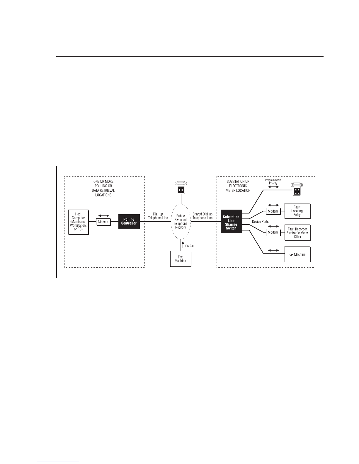
Figure1 illustratesa typical application,in whicha singletelephoneline isshared
by fourdevices.The Polling Controllerisadded to your existinghardware atthe
data retrieval location.
The SLSS offers many benefits, some of which include its ability to:
• Share a single substation telephone line between up to eight devices.
• Eliminate expensive telephone line installation and monthly charges for
briefly used modem lines.
• Ensure correct call routing by using a Polling Controller.
• Enhance worker safety by giving priority to telephone users.
• Hide substation modems from unauthorized access.
• Obtain high reliability and availability with a unit providing C37.90 SWC
protection to attached devices and powered from 42-150 VDC batteries
(“A” and “B” models only) or 90-150VAC (“D” model only) or 90-220VAC
(“E” model only).
40-400-00031, Rev. A Page 3
Figure 1 Typical SLSS Application
Page 12
Substation Line Sharing Switch
Chapter 3: Installation
CAUTION:
(1) Never install telephone wiring during a lightning storm.
(2) Never install telephone jacks in wet locations unless the jack is specifically designed for wet locations.
(3) Never touch uninsulated telephone wires or terminals unless the telephone line has been disconnected
at the network interface.
(4) Use caution when installing or modifying telephone lines.
Are You Ready?
Check that you have:
❑ Received an SLSS model M-395-A,B, D, E, M-396-A, B, D, or E. (The model
number is printed on the back of the unit.) Models ending in “-B , -D, or
-E” have the Auxiliary Relay.
❑ Received an Installation Kit which includes: two mounting brackets, two
tie cables, four pan-head slotted screws, four #12 flat washers, four #12
washer locks, four #12 wood screws, and four pan-head screws.
❑ Filled out and returned the Product Registration card.
❑ Collected enough standard modular telephone cords to connect the add-on
devices like modems, fax machines, meters, etc. to the SLSS. (The cords are
available as an ordering option.)
Installing the SLSS
Follow the appropriate steps below to wall-mount or mount the SLSS in a
standard 19" equipment rack. The brackets included in the installation kit are
used to mount the SLSS to a wall or to center- or front-mount the SLSS in an
equipment rack.
❑ To mount the SLSS on a wall, remove and discard the lower two center
screws on the SLSS side panels. Connect the short side of the mounting
brackets to the SLSS using the pan-head (round) screws provided. Then,
attach the mounting brackets to the wall with the supplied wood screws.
-or-
❑ To center-mount the SLSS in Equipment Rack, locate the center-most
screw holes and remove the two screws on the SLSS side panels and
discard. Use the pan-head (round) screws in the installation kit to attach
the brackets. Insert the SLSS into the rack and secure it with the provided
screws.
-or-
Page 4
Page 13
Reference Manual Chapter 3: Installation
❑ To front-mount the SLSS in Equipment Rack, remove the screws below
the threaded insert closest to the front of SLSS. Use the screws provided in
the installation kit to attach the the mounting bracket to the two vertical
holes closest to the SLSS front panel. Install the SLSS in the equipment
rack and secure it with the supplied screws.
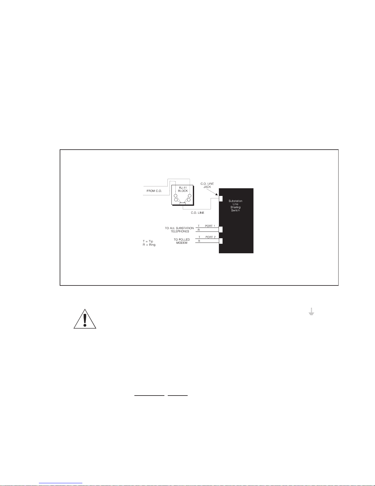
❑ Locate the incoming Central Office telephone (CO) and plug it into the CO
Line jack on the back of the SLSS. (The incoming line comes from the
telephone RJ-11/wall jack.)
❑ Verify that the polarity of the incoming telephone line is correct. For more
detail, see Appendix 2: Troubleshooting.
RT
4
3
4
3
Figure 2 Installing the Central Office Telephone Line
❑ Connect the protective grounding to the screw above this symbol on the
barrier strip on the back of the SLSS. The SLSS must be grounded to operate
properly.
❑ Connect the SLSS to the incoming line in front of any other devices: all
devices that will be used with the SLSS must plug into it.
❑ If there are multiple CO lines, check the telephone numbers assigned to
each line to determine which connects to the SLSS.
❑ Plug a touchtone (DTMF) telephone into Port 1.
❑ Connect other devices (modems attached to fault recorders, meters, etc.) to
any of the other ports with standard telephone cords.
40-400-00031, Rev. A Page 5
Page 14
Substation Line Sharing Switch
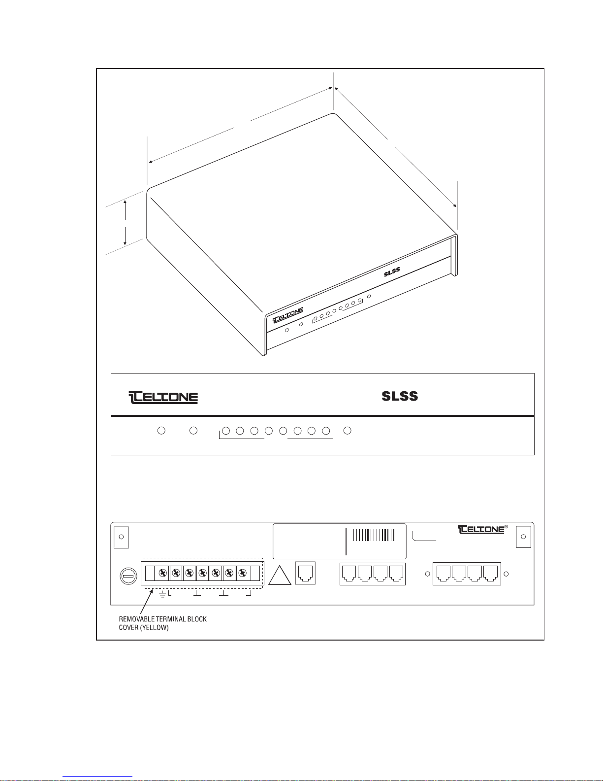
2.37"
12.00"
STATUS
ALARM
11.80"
Substation Line Sharing Switch
8
7
AUX
6
®
5
4
3
2
PORTS
1
STATUS
CAUTION:
FOR CONTINUED PROTECTION
AGAINST RISK OF FIRE,
REPLACE ONLY WITH SAME
TYPE AND RATING OF FUSE.
1.5AMP,
SLO-BLO,
3AG, 250V
FUSE
®
Substation Line Sharing Switch
12345678
ALARM AUXPORTS
SLSS Front Panel
THIS DEVICE COMPLIES WITH PART 15
OF THE FCC RULES. OPERATION IS
SUBJECT TO THE FOLLOWING TWO
CONDITIONS: (1) THIS DEVICE MAY NOT
CAUSE HARMFUL INTERFERENCE, AND
(2) THIS DEVICE MUST ACCEPT ANY
INTERFERENCE RECEIVED, INCLUDING
INTERFERENCE THAT MAY CAUSE
UNDESIRED OPERATION.
MODEL NO.:
UNIT NO.:
PART NO.:
MFG DATE:
WARR DATE:
PATEN 5,241,587
PATENT PENDING
LOAD NUMBER: XX
COMPLIES WITH PART 68, FCC RULES
FCC REG NO.: XXXXXX-XXXXX-XX-X
RINGER EQUIVALENCE: X.XB
!
A1 R1
-
ALARMS AUX42-150 VDC
A2 R2+
C.O.
LINE
SLSS Rear Panel
Figure 3 Substation Line Sharing Switch (M-396-B-01)
PORT
PORT
1
PORT
PORT
2
4
3
PORT
5
Bothell, WA U.S.A.
Made in U.S.A.
PORT
PORT
7
6
PORT
8
Page 6
Page 15
Reference Manual Chapter 3: Installation
❑ (Optional) Connect alarm monitoring equipment to the internal dry
contact alarm relay terminating at the barrier strip screws labeled A1 and
A2.
❑ For the “A” and “B” models, connect the power (42 - 150 VDC) leads to the
positive (+) and negative (-) screws on the barrier strip on the back of the
SLSS.
❑ For the “D” model, connect the power (90-150 VAC)) leads to the Line (L)
and Neutral (N) screws on the barrier strip on the back of the SLSS.
❑ For the “E” model, connect the power (90-220 VAC)) leads to the Line (L)
and Neutral (N) screws on the barrier strip on the back of the SLSS.
❑ Provide power to the SLSS and check that all LEDs light momentarily. The
Status LED will blink indicating the SLSS is idle. If power is lost to the SLSS,
a direct path between the C.O. Line port and Port 1 is maintained.)
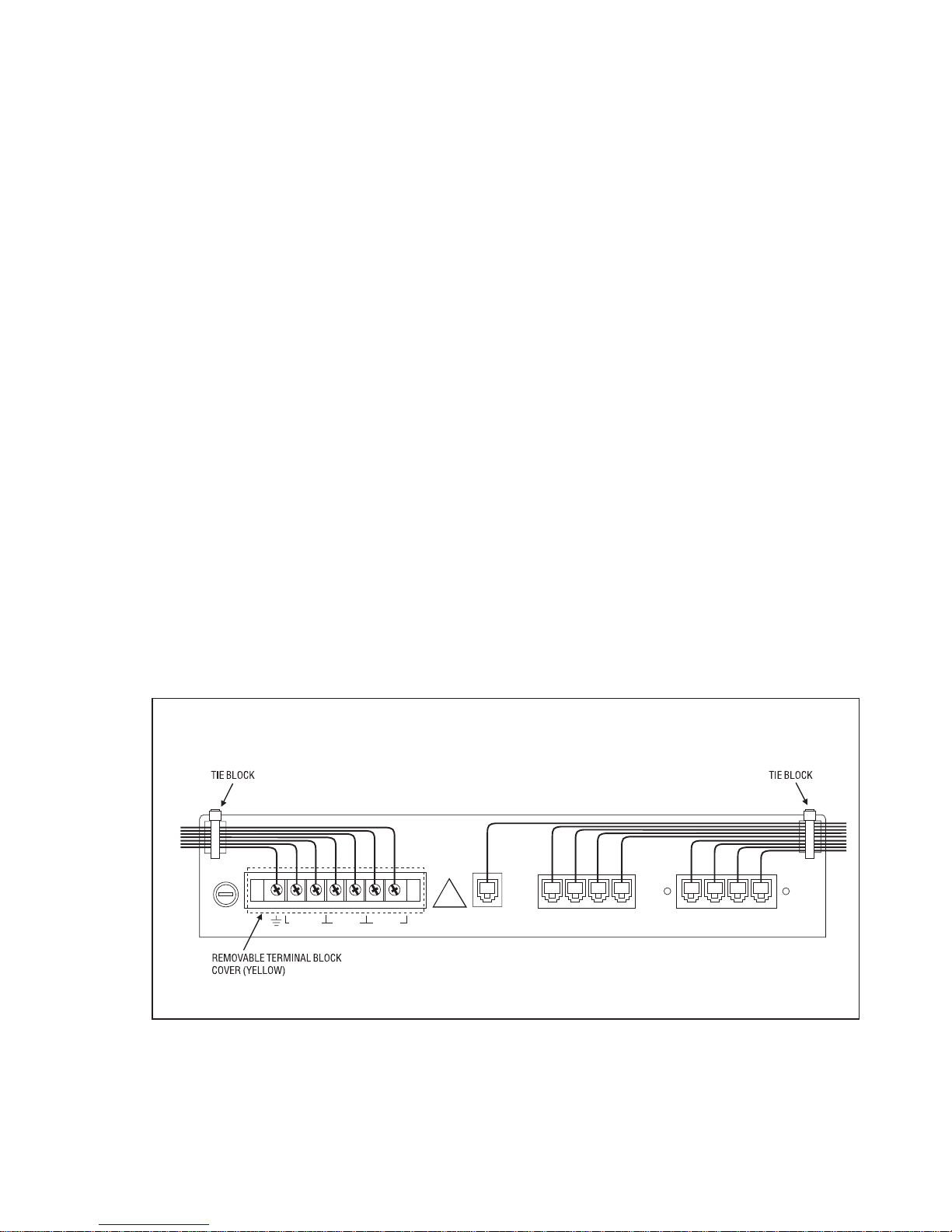
❑ Run the wiring for the terminal block to the left of the unit, through the tie
block. Secure the wires using the “zip” ties.
❑ Replace the yellow terminal block cover.
❑ Run the CO Line and all port cabling to the right, through the tie block.
Secure the wires using the “zip” ties.
Route the wiring as shown to prevent noise on the telephone line.
!
FUSE
A1 R1
-
ALARMS AUX42-150 VDC
A2 R2+
C.O.
LINE
SLSS Rear Panel
PORT
PORT
PORT
PORT
2
1
4
3
PORT
PORT
5
6
PORT
PORT
7
8
40-400-00031, Rev. A Page 7
Figure 4 SLSS Wiring Example
Page 16

Substation Line Sharing Switch
Install Polling Controller (optional)
If you are using the SLSS with the Polling Controller, follow these steps. These
instructions are repeated in the Po lling Controller Reference Manual,
40-400-00013.These stepsrequireapersonatboth thePolling ControllerandSLSS
locations.
❑ Plug the incoming Central Office telephone line into the Telco Line port on
the back panel of the Polling Controller. (The incoming line comes from the
telephone RJ-11/wall jack.)
❑ Connect another standard modular telephone cord from the modem to the
Modem port on the back of the Polling Controller. (The cords are available
as an ordering option.)
❑ Connect a standard RS-232 cable from the modem to the computer (PC,
mainframe, or workstation) used to control polling.
❑ Connect the PS-24DC-01 power transformer cord to the jack labeled: Class
2 Input Power Pack, on the rear of the Polling Controller. Plug the power
transformer into a 120 VAC outlet.
❑ If you are using multiple Polling Controllers, see the Installing Multiple
Units in Carrier instructions in the Polling Controller Reference Manual
(40-400-00013).
❑ The power LED on the back panel should be flashing. If not, check that the
power is securely connected. (If the LED does not light, check the power
connection and fuse. If the LED is on bright, but does not flash, see the
Troubleshooting instructions in the appendix.)
❑ Place a call to the telephone connected to Port 1 on the SLSS. The call
should be answered by the SLSS on the first ring and the Port 1 telephone
should ring after four seconds. Answer the phone, then hang up.
❑ The system is ready to go to work. To call one of the ports on the SLSS, dial
the SLSS telephone number and add a routing code to the end.
❑ Test that calls are routed properly by plugging a device into Port 3 on the
SLSS, then call the SLSS and enter the routing code for Port 3. Check that
Port 3 rings and that the LED flashes on and off.
❑ Forexample: CallPort 3on theSLSS bydialing 1-206-555-1212∗03from aphone
plugged into the Polling Controller.
❑ Routing codes ∗01-∗08 sends calls to Ports 1-8 as follows: ∗01 routes calls to
Port 1, ∗02 to Port 2, and ∗03 to Port 3, etc.
❑ (Optional.) If you will not be using the default settings, see Programming
Tips in Chapter 4. To program the Polling Controller, refer to the Polling
Controller Reference Manual (40-400-00013).
Page 8
Page 17

Reference Manual Chapter 3: Installation
Setup Standalone Operation
Follow the steps below to setup the SLSS to work without a Polling Controller.
Note:
the Polling Controller must be re-programmed with transfer codes which
match those of the SLSS.
Remember that if the SLSS will ever work with a Polling Controller,
❑ Disconnect the incoming CO line from the SLSS.
❑ Connect a DTMF telephone to Port 2 of the SLSS.
❑ Pick up the phone and enter # # within 15 seconds.
❑ When you hear the three-beep confirmation tone, enter ∗00#∗02# to
activate the Standalone defaults. Listen for the three-beep confirmation.
❑ Hang up the telephone and reconnect the incoming CO line to the SLSS.
❑ The power LED on the front panel should be flashing. If it is not, check that
the power is securely connected. (If the LED does not light, check the
power connection and fuse. If the LED is on bright, but does not flash, call
Technical Support.)
❑ Call the telephone connected to Port 1. The call should be answered by the
SLSS on the first ring and the Port 1 telephone should ring after four
seconds.
❑ Answer the phone, then hang up.
❑ Now you can call a port on the SLSS by adding the Standalone transfer
codes to the end of the SLSS phone number. (Standalone transfer codes
11-88 access Ports 1-8 as follows: 11 accesses Port 1, 22 accesses Port 2, and
33 accesses Port 3, etc.) See Chapter 4: Changing Transfer Codes to program
new codes.
❑ For example, to call Port 2, dial the SLSS number. Enter 22 after the first ring
(within 4 seconds).
-or-
❑ If you will not be using the Standalone Defaults, review the Programming
Tips in Chapter 4 and follow the Standalone SLSS Programming, also in
Chapter 4.
❑ (Optional) To call through a modem, remember to give the receiving
modem time to answer by adding pause time (,,,,) between the SLSS
telephone number and the transfer code.
If the modem does not answer properly, add or remove commas. If the call
defaults to Port 1, the pause is too long and you should remove one or
more commas. When adding or removing commas, do so one at a time.
40-400-00031, Rev. A Page 9
Page 18

Substation Line Sharing Switch
The number of commas you will add depends on the time required for the
network to process your call and for the SLSS to answer the call.
❑ For example, to send a call to Port 3, dial: 1-206-555-1212,,,,33
Note:
The guesswork involved in determining the correct number of pauses
is why many users decide to use the Teltone Polling Controller.
❑ (Optional.) Continue to Chapter 4: Programming to review the Programming
Tips before following the Setup for Local, Remote or Standalone
Programming instructions.
Page 10
Page 19

Reference Manual Chapter 4: Programming
Chapter 4: Programming
Programming Tips
You can adjust or program many of features in the SLSS. All of the options and
commands are listed in Table 2, later in this chapter. The SLSS is programmed
using a touchtone telephone, either locally, without disconnecting the CO Line,
or remotely from the Polling Controller.
Passwords
Always enter # after entering a password. If an invalid password is entered, you
will not hear three beeps and should hang up and wait for 30 seconds before
trying again. If three consecutive invalid attempts are made, the SLSS will lock out all
further access for 1 hour. (M-395-B, D, E models only: If secure relay access is
enabled, the SLSS will allow 5 consecutive invalid attempts.)
Note:
this password.
Remote Programming
Remote Programming must be enabled through Local Programming before you
can access the SLSS remotely. When you have finished programming remotely,
exit by hanging up the telephone. You cannot disable the Remote Programming
feature while in Remote Programming.
ConfirmationTone
When a command has been entered successfully, you will hear a three-beep
confirmation tone after entering the last #.
ErrorTone
When a command has been entered incorrectly, you will hear a single-beep error
tone after entering the last #.
Enable/Disable
With functions that are either enabled or disabled, such as fax routing, an entry
of 0 in the data field disables a feature; 1 enables it.
The password used to access the Auxiliary Relay must be different from
Cancel Command
To canceltheentire command, enter ∗in a command field. To cancel a command,
back to, but excluding the #, enter ∗ in a data field. To abort the entire command,
enter ∗∗ in a data field. If no data is entered in a field, that field is either cleared
or set to zero.
40-400-00031, Rev. A Page 11
Page 20

Substation Line Sharing Switch
Transfer Codes
When assigning transfercodesfor remote programming or for ports (commands
∗07#n#x# and ∗12#y#n#x#), follow these rules:
• Transfer codes must have the same number of digits, be no more than four digits
long, be unique (i.e., all codes must be different), and can use any of the 16 DTMF
digits.
• If you do not use the defaults, all codes must be programmed in both the
SLSS and Polling Controller.
Entering Programming Commands
You canenter the commands in any order. If you will not use aparticular feature,
skip to the next and continue programming.
Threebeeps tell youthat the SLSSreceivedthe command.One long tonetellsyou
that the command was incorrect and must be entered again. If you make a
mistake, simply re-enter the command correctly.
To enter a command, replace “n,” “x,” and “y” with the desired values.
❑ For example, to change the number of rings before disconnect from 12 to 10,
enter
∗01#10#.
❑ For example, to change the password to 1234, enter ∗03#1234#1234#.
❑ For example, to change the Port 2 transfer code to 8802, enter *12#2#4#8802#
Setup for Remote Programming with a Polling Controller
Note:
Emergency Priority. If one of these priority modes is enabled, Port 1 will be
able to interrupt programming.
The SLSS will exit programming mode and disconnect if 60 seconds elapse
without entry of any digits.
The factory default for Remote Programming is enabled. If you have disabled
Remote Programming, it must be enabled before you can program.
You can access the SLSS for programming from the Polling Controller using a
special transfer code. You must enter a password after entering the Remote
Programming Transfer Code. The transfer code instructs the SLSS to answer
without ringing any of the device ports. Proceed as follows:
Programming may be interrupted if you have enabled Total or
❑ Disconnect the Polling Controller from the host modem.
❑ Plug a DTMF telephone into the Modem port on the Polling Controller.
Page 12
Page 21

Reference Manual Chapter 4: Programming
❑ Dial the number of the SLSS, adding the #7 routing code to the end of the
number. (This is the Polling Controller default for the Remote
Programming Transfer code.)
❑ When the Polling Controller connects to the switch (you will hear three
beeps and the LED flashes), enter the password within 30
seconds: 8358663# (The default is “Teltone”.)
If an invalid password is entered, there will be no acknowledgment of any
kind. Hang up and wait for 30 seconds before trying again.
❑ When you hear the three-beep confirmation tone, begin programming or
follow the example below. (If you decide to program, please review the
example first.)
Example: Remote Programming with Polling Controller
If you follow the steps in this example, remember to reprogram the settings to
match your application.
❑ Enter ∗50#1# to enable Emergency Priority. When you hear 3 beeps, enter
another command or exit programming mode. If you hear error tone, enter the
command again.
❑ Enter ∗51#1#911#911# to enter the number 911 as the first emergency priority
number. Listen for three beeps.
❑ Enter ∗51#2#18004263926#18004263926# to enter the number 1(800)
426-3926 as the second emergency priority number. Listen for three beeps.
❑ Enter ∗03#8378#8378# to change the password to “test”(8378).Listenfor three
beeps.
❑ Enter ∗06#2# to enable Port 2 to handle fax routing. Listen for three beeps.
❑ Enter ∗09# to exit programming mode. Hang up.
❑ Redial the unit, adding #7 to the end of the number.
❑ Listen for three beeps and watch the LED change, then enter 8378# (test#)
within 30 seconds to check the new password. Listen for three beeps.
❑ Enter *74#1# to enable the Auxiliary Relay. Listen for three beeps.
❑ If you have followed this example and wish to return to the factory defaults, enter
∗00#∗01# Listen for three beeps. Enter *09# and hang up the phone.
-or-
❑ If you wish to use the changes made in this example, enter ∗09# to exit
programming mode.
40-400-00031, Rev. A Page 13
Page 22

Substation Line Sharing Switch
Setup for Local Programming
Note:
elapse without entry of any digits.
You can program the SLSS locally with the CO line connected and by using a
password or locally with the CO line disconnected, without a password. The two
sections below, describe both options. Select one.
If the Central Office line is connected to the SLSS:
The SLSS will exit programming mode and disconnect if 60 seconds
❑ Connect a DTMF telephone to SLSS Port 1
❑ Go off-hook and dial ##within 15 seconds. You will not hear a confirmation
tone from the SLSS.
❑ Enter the password within 30 seconds. (The default password is: 8358663#
“Teltone”).
Note:
and wait for 30 seconds before trying again.
If an invalid password is entered, you won’t hear three beeps. Hang up
❑ When you hear the three-beep confirmation tone, begin programming.
Turn to the Local Programming Example for a typical programming session.
-or-
If the Central Office line is NOT connected to the SLSS:
❑ Connect a DTMF telephone to SLSS Port 2.
❑ Go off-hook and dial ##within 15 seconds. Listen for three beeps and begin
programming. Turn to the Example: Local Programming for a typical
programming session.
Page 14
Page 23

Reference Manual Chapter 4: Programming
Example: Local Programming
If you follow the steps in this example, remember to reprogram the settings to
match your application when you finish.
❑ Enter ∗11#2#1# to enable audible ringback on Port 2. When you hear 3 beeps,
you may enter another command or exit programming mode. If you hear error
tone, enter the command again.
❑ Enter ∗50#1# to set Emergency Priority. Listen for 3 beeps.
❑ Enter ∗51#1#911#911# to set 911 as the first emergency priority number. Listen
for 3 beeps.
❑ Enter ∗51#2#4871515#4871515# to set the number 487-1515 as the second
emergency priority number. Listen for three beeps.
❑ Enter *74#1# to enable the Auxiliary Relay. Listen for three beeps.
❑ If you have completed the example steps and will not use these values, enter
∗00#∗01# to return to the factory defaults. Listen for three beeps and hang up.
-or-
❑ If you wish to use the changes made in the above example, hang up the
telephone.
40-400-00031, Rev. A Page 15
Page 24

Substation Line Sharing Switch
Setup SLSS Standalone Programming
Please see Chapter 6 for detailed descriptions of Standalone SLSS operation and
features. If you are using the SLSS as a Standalone unit, you can access the unit
from a standard touchtone telephone.
❑ Read the example of Standalone Local Programming, then follow the steps
below.
❑ Disconnect the telephone line from the CO line.
❑ Connect a touchtone telephone to Port 2.
❑ Pick up the phone, press # #, and listen for three beeps.
❑ Enter ∗00#∗02# for operation with Standalone defaults.
❑ If you want to change any Standalone values, select a feature from Table 2
and write out all commands in the Customer Settings column provided in
Table 2.
Example: Standalone Local Programming
❑ Enter ∗12#1#2#∗1# to set the new two-digit transfer code for Port 1 to ∗1. (You
have 60 seconds.)
❑ To set the transfer code to *2 for Port 2, enter: *12#2#2#*2#.
❑ To set the transfer code to *3 for Port 3, enter *12#3#2#*3#.
❑ To set the transfer code to *4 for Port 4, enter *12#4#2#*4#.
❑ To enable remote programming, enter: ∗02#1#.
❑ To set the remote programming transfer code to #9, enter: ∗07#2##9#.
❑ Write these codes, along with any others you have entered, into the Customer
Settings column in Table 2 for future reference.
❑ If you will not use the values in this example, enter ∗00#∗02# to return to the
Standalone defaults.
❑ Hang up the telephone, then connect and test the SLSS by following the steps
in
Installing the SLSS
Note:
the restrictions listed in Table 2.
For the example above, you may substitute transfer codes according to
section.
Page 16
Page 25

Reference Manual Chapter 4: Programming
Access Standalone Remote Programming
❑ Continue if:
You have assigned a remote programming transfer code. If not, please
return to Standalone Local Programming and follow the instructions.
Remote Programming is enabled (default). If it is not, follow the Standalone
Local Programming instructions to enable it.
The CO line is plugged into the CO Line jack on the SLSS.
❑ Dial the SLSS telephone number.
❑ Within 4 seconds after the first ring, enter the remote programming
transfer code. (If, for example, you followed the Example: Standalone Local
Programming, the Transfer Code for Remote Programming would be #1.)
❑ Listen for three beeps, then enter the password: 8358663# (default)
If you do not hear three beeps, hang up for 20 seconds and dial the SLSS
again.
❑ Enter ∗00#∗02# to bring up the Standalone defaults. Listen for three beeps.
❑ To change the Standalone values, select a command from Table 2 and
begin programming. It is best to write out all commands in the Customer
Settings column provided in Table 2.
Example: Standalone Remote Programming
❑ After completing the steps above, continue.
❑ To change the Port 3 transfer code to *3, enter ∗12#3#2#*3#.Listen for three
beeps.
❑ To change the Port 4 transfer code to *4, enter: ∗12#4#2#*4#. Listen for three
beeps.
❑ To enable Post Call Routing, enter: ∗08#1#
❑ To change the number of rings to 4, enter ∗01#4#
❑ To disable Post Answer Transfer, enter: *76#0#
❑ If you will not use the entries from this example, enter ∗00#∗02# to return to the
Standalone defaults.
❑ When you have finished programming, enter ∗09# to exit remote programming.
Hang up the telephone.
40-400-00031, Rev. A Page 17
Page 26

Substation Line Sharing Switch
Example: Standalone Call with Post Call Routing
With the above example programmed into the SLSS, you could do the
following:
❑ Dial the SLSS telephone number and listen for the first ring.
❑ Enter the Port 3 transfer code: 33 within 4 seconds.
Port 3 will ring and you will hear a high-pitched tone (i.e., the Transfer
Code Acknowledge Tone).
❑ Answer the Port 3 call and hang up the Port 3 device when finished.
❑ To route to another port on the SLSS during the same call, enter 44 when
you hear dial tone. Port 4 will ring, but you won’t hear the Acknowledge
Tone or three beeps.
❑ Hang up when the last call is finished.
Example: Standalone Call with Post Answer Transfer
Withthe above example programmed into the SLSS, you could do the following:
❑ Dial the SLSS telephone number and listen for the first ring. Answer the
call on the Port 1 telephone.
❑ To transfer the call to Port 3, enter: #03 within 15 seconds.
Port 3 will ring and you will hear a high-pitched tone.
Note: Post Answer Transfer allows a call to be re-routed ONLY from Port 1.
(The purpose is to allow the answering party to re-direct a call.
Page 18
Page 27

Reference Manual Chapter 4: Programming
Table 2 SLSS Programming Commands
Command Description
Valid
entries
(x=/y=/n=)
Factory
Default
Customer
Settings
Standalone
Defaults
Reminder: Beforeprogramming, please review Programming Tips earlier in this chapter. Then, enter your selections
in the Customer Settings column to keep track of the unit’s settings. We suggest you make your entries in pencil, as
you
may wish to change them at a later date.
*00#*00# Restore Defaults: Use this command
only if you purchased the SLSS with
Customer DefinedDefaults: it resets
the SLSS to Customer Defined Defaults.
*00#*01# Restore Factory Defaults: Always
resets SLSS to the Factory Default
settings, even if you ordered Customer
Defined Defaults.
Note: If you ordered Customer Defined
Defaults and use this command, you
can return to the Customer Defined
Defaults by entering *00#*00#
(Restore Defaults).
*00#*02# Fetch Standalone Defaults: Resets the
unit to the defaults listed in the
Standalone Defaults column.
Note: When youenter one of the three commands above (*00#*00#, *00#*01#, or *00#*02#), you must
reprogram emergency telephone numbers.
*01#x# Number of Rings: Sets the number of
times the SLSS will ring any port before
1-50 12 12
disconnecting.
*02#x# Remote Programming: Enables or
disables remote programming.
This command can only be entered from
0=disabled
1=enabled
11
Local Programming.
*03#x#x# Programming Password: Sets the
password for both local and remote
programming. The passwordmust be
enteredtwice, as shown. See the note
3-10 digits,
any DTMF
digits except
#
8358663
ÉTeltoneÊ
8358663
ÉTeltoneÊ
below.
*04#x# Dialtone Type: Sets the type of dial tone
sent by the SLSS to a user attempting
0=standard
1=stuttered
emergency access. If 0 is selected, the
user hears standard dial tone. If 1 is
00
selected, you hear stuttered tone,
indicating that you have not reached
Central Office dial tone.
40-400-00031, Rev. A Page 19
Page 28

Substation Line Sharing Switch
Table 2 SLSS Programming Commands
Command Description
*05#x# Privacy Timeout: Enables or disables
the privacy timeout feature. A port will
timeout and hang up the C.O. line if it
goes off-hook for 30 seconds and no
digits are dialed. (See page 30.)
*06#x# Fax Routing: Sets the port to which the
SLSS directs a fax call when it receives
a CNG signal.
*08#x# Post Call Routing: Enables or disables
port transfer from one port to another if
the first port does not answer or after a
call is complete.
*10#y#n# Port Off-hook Timeout: Limits the time
allowed for a single call on a port.
*11#y#n# Audible Ringback: Enables or disables
audible ringback with calls to a port.
Valid
entries
(x=/y=/n=)
0=disabled
1=enabled
0=disabled,
or
Ports 1-8
0=disabled
1=enabled
y=Port 1-8
n=0-255
minutes
y=Port, 1-8
n=0,
disabled
or 1, enabled
Factory
Default
Customer
Settings
Standalone
Defaults
11
00
00
n=0 0
n=0
n=1,
enabled
*50#x# Priority Type: Determines how
competing users will be given access to
the line. The default is Total Priority.
*51#y#x#x#Emergency Phone Numbers: When
emergency priority is enabled, this
command sets the phone numbers to
which a Port 1 user is allowed priority
access when the line is in use. Up to 10
different numbers can be programmed.
The phone number must be entered
twice, as shown.
*52#x#x# Emergency Access Code: When
Emergency Priority is enabled, this sets
the Access Code that a Port 1 user
enters to access the line to dial a
number that is not one of the
programmed ten.
*70#x# Delay Before Routing: Number of
seconds delayed before routing to the
default port or disconnecting, if no
default is set.
0=Total
1=Emergency
00
2 = No
y=1-10,
rank (1st,
2nd, 3rd,...)
of the
emergency
telephone
none none
number
x=phone
number,
0-16 digits
x=access
code,
0-16 digits
none none
4-30 seconds 4 4
Page 20
Page 29

Reference Manual Chapter 4: Programming
Table 2 SLSS Programming Commands
Command Description
*71#x# Answer Tone: Sets how the SLSS
responds when it has answered an
incoming call.
*72#x# Transfer Code Acknowledge:
determines how SLSS responds to a
transfer code. (Use this command only
when working with the Polling
Controller.)
*73#x# Select Default Port: Sets the default
port to which calls will be routed when
no transfer code is received.
*74#x# Auxiliary Relay: Enables or disables
Secure Mode of the auxiliary relay.
(Models M-395/396-B, D, and E only)
See page 33 for operating commands.
*75#x#x#
Password Access to Aux Relay:
Programs a password that must be
entered to access the aux relay. The
passwordmust be entered twice, as
shown. It must be different from the
SLSS Programming Password.
Valid
entries
(x=/y=/n=)
0=disable
1=confirm.
2=dial tone
0, none
1, modem
answer tone
2, ‘#B’
default port
number 1-8
0= no
default port
0=disabled
1=enabled
x=password,
3 - 10 digits
any DTMF
digit, except
#
Factory
Default
Customer
Settings
Standalone
Defaults
00
11
1=default
port
1
11
73529
“RELAY”
73529
“RELAY”
*76#x# Post Answer Transfer: Enables or
disables the abilityto transfer a call that
was answered on the Port 1 phone to
another SLSS port.
*77#x# Ring Detect: Setswhen the SLSS will
detect ringing. Use standard detect for
most applications. Use special detect to
allow calls to be answered during the
ring, not after. (Special detect should be
used with certain line isolators that do
not meet standard line requirements.)
*78#x# Auxiliary Relay Speed Mode: Enables
transfer code control of Aux Relay.
When the Speed Mode is disabled, relay
control is in Secure Mode if it has been
enabled.
0=disabled
1=enabled
0=standard
detect (at
end of first
active cycle)
1=special
detect
(between
300-400 ms
of ring start)
0=disable,
1=enable
11
00
00
40-400-00031, Rev. A Page 21
Page 30

Substation Line Sharing Switch
Table 2 SLSS Programming Commands
Command Description
*79#x# Speed Mode Detect Method: Sets
whether SLSS will look for proprietary
only or proprietary and standalone
transfer codes in Speed Mode
*07#n#x# Transfer Code for Remote
Programming: Sets the transfer code
for remote programming. Replace n with
the number of digits in the transfer code,
0-4. Valid digits for the transfer code
include: 1-9, 0, ∗, and #. Make sure
that remote programming transfer
codes are different from port transfer
codes.
*12#y#n#x#Transfer code for SLSS Ports: Sets the
transfer code for the SLSS ports. (If you
enter 0, the port will be outgoing only.)
Valid digits for the transfer code include:
1-9, 0, ∗, and #.
All port transfer codes must be unique.
# # is not a valid code.
Valid
entries
(x=/y=/n=)
0=detect
proprietary
codes and
standalone
codes
1=detect
proprietary
codes only
n= 0-4
x=transfer
code
y= 1-8, port
number
n= 0-4,
number of
digits in code
x=transfer
code, 0-9, *,
#, A-D
Factory
Default
Customer
Settings
Standalone
Defaults
00
unpublished #1
Port 1 = 11
Port 2 = 22
Port 3 = 33
unpublished
Port 4 = 44
Port 5 = 55
Port 6 = 66
Port 7 = 77
Port 8 = 88
Page 22
## Hang Up Default Port: To stop ringing
the default port before the programmed
number of rings. and hang up the
incoming telephone line.. This feature is
used when the SLSS is connected to a
line without forced disconnect, such as
a PBX line.
*09# Exit RemoteProgramming.
Page 31

Reference Manual Chapter 4: Programming
Changing Transfer Codes
Table 3 lists the routing codes that the calling modem sends to the Polling
Controller. The routing codes are receivedby the Polling Controller, which sends
a transfer code to the SLSS, telling it which port should get the call.
The default transfer codes are unpublished to protect the security of those who
choose not to program different values. Some people change the transfer codes
to increase security or to enable the SLSS to work with and without a Polling
Controller.
❑ Follow the Access Local Programming or Access Remote Programming
instructions earlier in this chapter.
❑ To change the unpublished factory defaults for the transfer codes, enter
new transfer codes in the middle column of Table 3.
❑ Program the new values using command: ∗12#y#n#x# (Transfer Codes for
SLSS ports)
❑ Example: Followtheappropriate steps to access the SLSSforprogramming with
or without the Polling Controller and either remotely or locally.
❑ Example: To change the transfer code for Port 3 to ∗13, enter: ∗12#3#3#∗13#
and listen for three beeps.
Note:
digits.
If youare using thefour-portmodel SLSS (M-395),youwill use onlythefirst four
routing codes. Codes ∗01-∗08 are used with the eight-port model SLSS (M-396).
Routing code *16 is used to pulse the Auxiliary Relay on M-395-B-01, D-01, E-01
or M-396-B-01, D-01, E-01 models only
All port transfer codes must be unique and have the same number of
Table 3 Routing Codes and Transfer Codes for SLSS Ports
Routing Codes (DTMF) New Transfer Code SLSS Port
*01 1
*02 2
*03 3
*04 4
*05 5
*06 6
40-400-00031, Rev. A Page 23
*07 7
*08 8
*16 Proprietary or 96 Only! Auxiliary Relay Pulse
Page 32

Substation Line Sharing Switch
❑ Program the Polling Controller to send the new transfer codes when it
receives the indicated routing codes. (Refer to Reference Manual PC-100
for Polling Controller programming instructions.)
Page 24
Page 33

Reference Manual Chapter 5: Polling Controller and SLSS Operation/Features
Chapter 5: Polling Controller and SLSS Operation/Features
If you are installing the SLSS, please return to Where To Start in Chapter 1 after
reading this chapter.
Figure 5 Polling Controller and SLSS Operation
Basic Operation
When installed and working as a system, the SLSS and Polling Controller
communicate acrossthe
private telephone network to set up and disconnect calls, as well as to determine
priorities among devices and types of calls. For example: outgoing emergency
calls from the substation take priority over polling calls.
The SLSS answersincomingcalls, determines which port should getthecall, and
routes the call accordingly.
If a transfer code is received from a Polling Controller, the SLSS routes the call to
the requesteddevice,such as a polled modem. If no transfer code is received, the
call is routed to the default port (Port 1 is the factory default) which is usually
connectedto atelephone. Ifno defaultport isdefined,callswithouttransfer codes
are disconnected.
You can selectavariety of SLSS operations by programming the unit remotelyor
locally (on-site) using a touchtone telephone.
TheSLSS canbeused withorwithoutaPolling Controller. However, Teltonehighly
recommends that the SLSS be used with a Polling Controller. When used without a
PollingController,thecallermustbesurethe SLSSanswers thecallbeforetransfer
codes are sent to route the call.
public switched telephone network (PSTN) or a utility’s
40-400-00031, Rev. A Page 25
Page 34

Substation Line Sharing Switch
An advantage of using the Polling Controller is that the user does not need to
generate thepause time (,,,,) inthedial string betweenthetelephone number and
routing code to accommodate network delays. (The pause time is a series of
commaswhich givestheSLSS timetoanswerthecall beforeitreceivesthetransfer
code.) In addition, the Polling Controller will hang-up polling calls at the
originating end when a priority call starts at the SLSS.
Typical Call Sequence
When thePolling Controller andSLSS are workingtogetheras asystem,a typical
polling call from a host computer would progress as described below:
The host modem dials the SLSS to access a modem on Port 3 of the remote
SLSS, by dialing: 1-206-555-1212∗03
The Public Switched Telephone Network (PSTN) processes the call and rings the
remote SLSS.
As soon as the Polling Controller recognizes ∗03 as a valid routing code, it puts the
calling modem on hold. Then it starts sending a translation of the routing codes
(one to four digits). This translation or transfer code, is sent at regular intervals to
the SLSS so that when the SLSS answers the call, the transfer code is received
within a second or two. The transfer code is sent until the SLSS acknowledges
receipt or until the calling modem terminates the call.
The SLSS answers the call at the end of the first ring and waits for a transfer code
(you program the length of time, the Delay Before Routing, that the SLSS waits for
the code, the default is four seconds). If the SLSS does not receive a transfer
code, it rings the default port; the factory default for this is Port 1.
When the SLSS recognizes the valid transfer code for Port 3, it rings Port 3 and
sends an acknowledgment tone to the Polling Controller.
When the Polling Controller recognizes the acknowledgment tone, it removes the
hold so that the calling modem will be listening when the receiving modem
attached to Port 3 answers the data call.
Note:
A modem answer tone is used as an acknowledgment tone so that a
Polling Controller can be used to dial remote modems when no SLSS is
installed.
At this point, the Polling Controller and SLSS have established a path for the data
call, enabling the calling and answering modems to communicate.
Page 26
Page 35

Reference Manual Chapter 5: Polling Controller and SLSS Operation/Features
Operational Details
Transfer Codes
When the Polling Controller receives routing code, it translates it into a transfer
code and sends the transfer code to the SLSS. These codes determine the SLSS
port to which a call is routed.
The SLSS arrives from the factory with unpublished transfer codes which you
can change. (Please refer to Tables 2 and 3.) Each SLSS port must have a transfer
code of one to four digits in length.
If you are using the SLSS as a standalone unit, the transfer codes can be sent
without a Polling Controller from a DTMF telephone or modem. (Please see
Standalone SLSS Operation for more detail.)
Calling Party Supervision
The U.S.telephone network typicallyuses Calling PartySupervision. This means
that even though the called party hangs up, she/he may be reconnected to the
calling partywhen her/his phone is takenoff-hook again. The callingparty must
hang up in order for the called party to be fully disconnected to initiate a new
call. The telephone network will time out and automatically disconnect the call
within 5 - 20 seconds, depending on network design. This will allow the called
party to get dial tone when she/he goes off-hook again.
To circumvent this problem, when the SLSS senses a priority interrupt it
immediately signalsthe Polling Controller to disconnecttheoriginal polling call.
This ensures that the user initiating the priority will be able to complete the
priority call.
If for any reason the interrupted call cannot be terminated within 5 seconds, a
busy tone is returned to the priority caller. The caller should then hang up for a
few seconds before trying the call again.
Outgoing Calls from the SLSS
The SLSS allows DTMF and rotary dialing on outgoing calls.
Outgoing Telephone Calls—SLSS Idle
When the SLSS is idle and a phone goes off-hook, the port is switched to the
Central Office line and the caller hears dial tone. When the phone goes on-hook,
the SLSS is idle again. (When the SLSS is idle, the ports connect to a local battery
feed.)
Outgoing TelephoneCalls—SLSS Active
InTotalPriorityMode a higher-priorityportis given accessto the linewhenever
it goes off-hook.
40-400-00031, Rev. A Page 27
Page 36

Substation Line Sharing Switch
If the SLSS receives no response from the Polling Controller after trying to
disconnect threetimes, the SLSS disconnects andthe calling party hearsdialtone
from the Central Office.
In Emergency Priority Mode, the telephone at Port 1 receives dial tone and the
caller can dial one of the programmed emergency numbers. (If a dialed phone
number does not match the listed numbers, the caller hears a busy signal.) If the
dialed number matches a programmed emergency phone number, the line is
freed for the telephone. The SLSS then dials the number and connects the
telephone totheCentral Office line. The callermust enter the emergencynumber
within 30 seconds or Port 1 will go into Privacy Timeout. (See page 30.)
Whenever Port 1 goes off-hookin Emergency Priority Mode, the caller hearsdial
tone sent by the SLSS, not by the network. The tone can be standard or stuttered.
Usingthe stuttereddial tonetellsthe callerthat theyare dialingthroughtheSLSS,
not directly through the network.
If you have programmed an Access Code, the SLSS will connect to the Central
Officelinewhenthetelephone calleronPort 1entersthe accesscode.Afterhe/she
hears dial tone, any number can be dialed.
Caution:
If an SLSS port is receiving an incoming fax when you go off-hook in
either Total Priority Mode or Emergency Priority Mode, the SLSS will be
unable to obtain network dial tone until the sending fax disconnects or until
the PSTN times out (usually within 10-15 seconds).
In No Priority Mode, the modem or other device remains active and the line is
not assigned to another port.
Fax Routing
When an incoming fax call arrives at the SLSS, the fax CalliNG (CNG) tone or a
transfer code directs it to the designated fax port. The SLSS will wait until the
Delay Before Routing period has elasped before ringing the default port, but a
CNG or transfer code received after the Delay Before Routing, and before the
default port is answered, will still route the fax call correctly.
Some faxes do not send the calling tone (CNG). If you have difficulty receiving
faxes on one of the SLSS ports and are using the unpublished factory transfer
codes (default), change the transfer code for the fax port to a two-digit code (e.g.,
22) so the caller can route faxes manually.
Loss of Power at the SLSS
Duringa powerfailure, telephonesconnectedto Port1 canreceiveand placecalls.
No other features of the SLSS will be available. Neither power failure nor
restoration will interrupt an ongoing call to Port 1. Incoming calls will be routed
to Port 1 if power is lost.
Page 28
Page 37

Reference Manual Chapter 5: Polling Controller and SLSS Operation/Features
Modem Disconnect on Loss of Carrier
Priority disconnection delay during a polling call is minimized if the polling
modem “Loss of Carrier” disconnect time is set to a minimum acceptable
duration. This duration is called the Modem Disconnect on Loss of Carrier and
is a programmable option on most modems. (Please refer to the manual
accompanying your modem for further information.)
Incoming Calls to the SLSS
When theSLSS is idle, Port 1 is notconnectedto the incoming CentralOffice line.
The SLSS answers all calls at the end of the first ring period, then looks for a
transfer code. If it gets a transfer code, the SLSS rings the appropriate port and
sends modem answertoneto the Polling Controller,acknowledging the transfer
code. The Polling Controller then connectsthepolling modem to the line so data
can be transferred. The SLSS then rings the designated port and when the local
modem answers, it connects the port to the Central Office line.
Interrupted Incoming Call at the SLSS
If a phone goes off-hook on Port 1 before an incoming call is connected to a port,
the SLSS connects Port 1 to the incoming call, and looks for a transfer code from
the Polling Controller.
Afterthe SLSSreceivesthetransfercode, ithandlescallsaccordingto theassigned
priority access mode (No, Total, or Emergency Priority):
• If the SLSS is programmed for No Priority, the call will be routed to the
appropriate port, and Port 1 will receive busy tone.
-or-
• If in Total Priority Mode, the SLSS will disconnect the incoming call and
connect Port 1 to the Central Office line. In this mode, lower number ports
always have priority over higher numbered ports; Port 2 can interrupt an
incoming call on Port 3, and Port 3 can interrupt Port 4, etc.
-or-
• If in Emergency Priority Mode, the SLSS sends dial tone to Port 1, and the
user dials one of the programmed emergency numbers. If the number
dialed is a valid emergency number, the SLSS will disconnect the incoming
call immediately and dials the emergency number as soon as it receives
dial tone from the network. The SLSS routes the call unless the caller is
denied access due to an invalid number, or 5 seconds elapsed since the last
digit was dialed.
40-400-00031, Rev. A Page 29
Page 38

Substation Line Sharing Switch
Polling Controller and SLSS Feature Operation
ProgrammingTransfer Codes
ThePolling Controllersends transfercodestellingtheSLSS theport towhich calls
should be routed. Calls can also be manually routed to any of the ports using a
one- to four-digit transfer code. The Transfer Code for Remote Programming is
used to enter programming mode. Please see Chapter 4 for more information. If
you have changed the defaults, the transfer codes must be programmed on both
the Polling Controller and the SLSS before the system will work properly.
Remote Programming
Remote programming offerspassword protection to provide additional security.
Thisfeaturemust beenabled viaLocalProgrammingtofurther protectthe system
from abuse.
Once remote programming has been enabled at the SLSS, you can program and
change the default password from the Polling Controller. When the SLSS is used
as a standalone unit, you can use any DTMF telephone connected to the SLSS to
change the password.
PrivacyTimeout
If“privacy timeout”is enabled,when anyport goesinto privacytimeout, theport
is disabled, the SLSS sends a forced disconnect (COD) to the port, and the SLSS
goeson-hook totheincoming (C.O.)telephonelinetoenable otherportsto receive
calls. The Privacy Timeout occurs after the SLSS detects: at least five seconds of
Central Office dial tone or two cycles of either busy or reorder tone during the
first 15 seconds of off-hook, no DTMF digits, and 5 or fewer rotary breaks dialed
in 30 seconds. The alarm LED will turn on until the the device on the port goes
on-hook.
Ifdial tone, busy, orreorderare notdetected,or dialingis detected,theSLSSlooks
for either a hook-flash or forced disconnect. If it detects either one, the SLSS will
start the privacy timeout period again. Incoming calls to other ports are routed
appropriately, but calls to the off-hook privacy phone get a busy signal.
If the port is returned to on-hook and then goes off-hook later, it will receive
Central Office dial tone normally.
Port Off-hook Timeout at the SLSS
TheSLSStimes outwhen theprogrammed maximumcall lengthis exceeded.The
SLSS sends a forced disconnect (COD) to the port, and the alarm LED will turn
on untilthe device attachedto the portgoes on-hook. Makesure thatthe off-hook
timeout is long enough to complete the longest data call.
Note:
If you have selected Emergency Priority, the off-hook timeout on Port 1
will be disabled.
Page 30
Page 39

Reference Manual Chapter 5: Polling Controller and SLSS Operation/Features
No Default Routing
Usethis featurewhen allof thedevicesconnectedto theSLSSareused forpolling,
including Port 1. It prevents the SLSS from routing calls without transfer codes
to Port 1.
If the SLSS does not detect a transfer code, the call is disconnected.
Note:
If power is lost, calls will be sent to Port 1, regardless of this feature.
PostAnswerTransfer
Withthis feature enabled, you can send a call that has been answeredby the Port
1telephoneto anotherSLSS port. To use thisfeature afteranswering a callon Port
1,enter thePost AnswerTransferCodefor thenext port.Once youhave answered
the call on Port 1, you have 15 seconds to enter a Port Answer Transfer Code.
Post Answer TransferCodes correspond to the port numbers. Replace the “x” in
#0x with the number of the port to which the call will be routed. For example,
to transfer a call to Port 2, enter #02, Port 3, enter #03, etc.
❑ For example,
15 seconds.
After answering it on Port 1,
send a call to Port 6 enter #06 within
❑ Hang up the Port 1 phone when you no longer hear the caller.
Post Call Routing
Withthis feature enabled you can send a transfer code to switch fromone port to
another after your current call is complete or the port you are calling does not
answer. In either case, when this feature is enabled, you have 15 seconds of dial
tone during which you can enter a new transfer code.
If, however, Port 1 goes off-hook and the priority mode is set to Emergency or
Total, Port 1 is givencontrolof the line. If Ports 2 through 4 or 8 go off-hook, they
are treated as No Priority.
To use this feature, the calling modem must be programmed not to hang up on
loss of carrier. Please see the modem’s manual for programming instructions.
❑ Make sure Post Call Routing has been enabled. If not, return to the Local or
Remote Standalone Programming instructions and do so.
❑ Dial the SLSS telephone number and enter your password when it answers.
❑ Wait for the Port 1 telephone to answer, then enter the Post Call Routing
Code for another SLSS port.
❑ For example, Enter the Port 3 transfer code: 33 within 4 seconds.
Port 3 will ring and you will hear a high-pitched tone (i.e., the Transfer Code
Acknowledge Tone).
❑ Answer the Port 3 call and hang up the Port 3 device when finished.
40-400-00031, Rev. A Page 31
Page 40

Substation Line Sharing Switch
❑ To route to another port on the SLSS during the same call, enter 44 when you
hear dial tone.Port4willring,butyou won’t hear the Acknowledge Tone or three
beeps.
❑ Hang up when the last call is finished.
Note:
To use this feature, the calling modem must be programmed not to
hang up on loss of carrier. Please see the modem’s manual for programming
instructions.
Port Access Priority at the SLSS
Youcan establishone of threetypesof prioritytodeterminehowcompeting users
or devices at the SLSS are given access to the line. This is determined by a
programming command, as described in Chapter 3. Total, Emergency, and No
are the priority modes.
If Total Priority Mode is enabled, Port 1 (normally a telephone) is given
immediate access to the line whenever the phone goes off-hook. If another port
is using the line (for example, data transfer is taking place), the modem is
disconnected and the line freed for the telephone user. Port 2 also has priority
access over Ports 3 through 8, but not over Port 1; Port 3 has priority access over
Port 4 through 8, but not over Ports 1 and 2, etc.
If Emergency Priority Mode is enabled, a Port 1 user is given priority when one
of the programmedemergency numbers is dialed.The SLSS can be programmed
to allow up to ten 16-digit numbers.
In this mode, all other ports work as if in Total Priority mode.
If you have programmed an Access Code, Port 1 will get access to the line
whenever the access code is entered, regardless of the number dialed.
Caution:
If an SLSS port is receiving an incoming fax when you go off-hook in
either Total Priority Mode or Emergency Priority Mode, the SLSS will be
unable to obtain network dial tone until the sending fax disconnects or until
the PSTN times out (usually within 10-15 seconds).
If No Priority Mode is enabled, no port can access the line when another port is
using it.
There arecertain conditions under which a caller making a priority interruptcall
at the SLSS may not be able to immediately obtain dial tone to make a priority
call. The user will experience a dial tone delay and/or receive a busy signal; he
should redial in these instances. If, however, the SLSS does not receive a transfer
code within four seconds of answering, it rings the default port. The SLSS will
disconnect if the following occurs:
• the telephone is not answered within 12 rings (12-50 rings).
• a forced disconnect is received from the Central Office.
• five seconds of dial tone are detected.
Page 32
Page 41

Reference Manual Chapter 5: Polling Controller and SLSS Operation/Features
Ring Detect
Formost applications,use thedefault setting,0. Changetheringdetectionsetting
to 1 only if you are using a line isolator that does not comply with Bellcore
specifications for ringing signaling. After programming *77#1#, the SLSS will
answer the call between 300 - 400 ms after start of the first ring.
Auxiliary Relay
If you have an M-395-B, M-395-D, M-395-E, M-396-B, M-396-D, or M-396-E
model, your SLSS includes a latching Auxiliary Relay. If a modem or other
microprocessor-controlled device locks up, the Auxiliary Relay can be
closed/opened or it can be pulsed closed for ten seconds to activate an external
latching relay which will cycle power to or reset the offending device(s) in the
substation.
Though the Auxiliary Relay will carry 125 VDC at up to 1 Amp, or 120 VAC
(E model 220 VAC) at up to 3 Amps, it is designed to be used with an external
relay.
Withthe Auxiliary Relay enabled, you can access it either locally in SecureMode
from the Port 1 telephone, or remotely in either a Secure Mode or a Speed Mode
from a touchtone telephone or modem. The default Auxiliary Relay position is
open and the default access mode is Secure Mode (see Table 2, page 21).
• Auxiliary Relay Secure Mode Operation
Secure Mode requires the user to enter a password before gaining access to
Auxiliary Relay operation. This mode requires more steps and works similarly
to entering programming commands, except that a special Relay Password is
used,not theSystem Password,and theuser isrestrictedto onlyrelay commands.
❑ To access the relay locally, pick up the Port 1 telephone, enter ##, to enter
the Programming Mode, then enter the Auxiliary Relay password (default:
73529). Be sure to terminate the password with the # delimiter.
-or-
❑ To access the relay remotely, call the SLSS through the Polling Controller
with #7 (if SLSS is using Factory Default programming access), or #1 ( if
other than Factory Default programming access), appended to the
telephone number. When the SLSS answers, wait for the three beep tone
indicating Programming Mode, Then enter the Auxiliary Relay password
(default: 73529) and listen for three beeps. Be sure to terminate the
password with the # delimiter. If no confirmation tone is received,
hang-up and repeat this step.
❑ To PULSE (close the relay for ten seconds), enter *31#. You will hear four
beeps after the relay closes, then two beeps after it opens. When you send
40-400-00031, Rev. A Page 33
Page 42

Substation Line Sharing Switch
the Pulse Auxiliary Relay command, the SLSS will not accept any other
commands for ten seconds.
❑ To CLOSE the relay, enter: *11#1# and listen for four beeps.
❑ To OPEN the relay, enter: *11#0# and listen for two beeps.
❑ To QUERY the relay about its status, enter: *21#. You will hear four beeps
if the relay is closed, two beeps if it is open.
❑ Hang up when finished.
• Auxiliary Relay Speed Mode Operation
SpeedModeoperation does notrequire youtoenter theProgrammingMode and
you use transfer codes rather than programmingcommandsto operate the relay.
The Speed Mode (default: Disabled) must be enabled once while in the System
Programming Mode . Several operations (transfer codes) can be strung together
if the SLSS is also programmed for Post Call Routing (see page 31).
❑ To PULSE (close the relay for ten seconds), when calling through the
Polling Controller with either a modem or a telephone, simply append *16
to the telephone number. You will hear four beeps after the relay closes,
then two beeps after it opens. When you send the Pulse Auxiliary Relay
transfer code, the SLSS will not accept any other transfer codes for ten
seconds.
❑ To CLOSE the relay, using the Polling Controller, one of the available but
un-used routing codes must be programmed to send the transfer code 97
to the SLSS.
❑ To OPEN the relay, using the Polling Controller, one of the available but
un-used routing codes must be programmed to send the transfer code 98
to the SLSS.
❑ To QUERY the relay about its status, using the Polling Controller, one of
the available but un-used routing codes must be programmed to send the
transfer code 99 to the SLSS. You will hear four beeps if the relay is closed,
two beeps if it is open.
❑ Hang up when finished.
AsummaryofallAuxiliaryRelay commandsandtransfer codesarelisted inTable
4 on page 35..
Page 34
Page 43

Reference Manual Chapter 5: Polling Controller and SLSS Operation/Features
Table 4 Auxiliary Relay Secure Mode Commands
and Speed Mode Transfer Codes
Secure
Mode
Com-
mands
*11#x#
*21#
*31#
Description
Auxiliary Relay Closed/Open: Toggles the
relay “Closed” or “Open.”
Auxiliary Relay Status: Checks the status
of the relay. Four beeps indicate that the
relay is closed, two beeps indicate it is
open.
Auxiliary Relay Pulse: Pulses the relay
closed for ten seconds, then opens it. The
SLSS does not accept any other
commands during this ten-second period.
Valid
entries (x =)
0 = relay
open
1 = relay
closed
—
—
(when relay is opened)
SLSS
Response
Closed = 4 beeps
Open = 2 beeps
Closed = 4 beeps
Open = 2 beeps
Closed = 4 beeps
(when relay is closed)
Open = 2 beeps
Speed
Mode
Transfer
Codes
96
97
98
99
Description
Auxiliary Relay Pulse Transfer Code:
Pulses the relay closed for 10 seconds
Note: The Auxiliary Relay can also be
pulsed using the Polling Controller by
appending the routing code *16 to your dial
string.
Auxiliary Relay Close Transfer Code:
Closes Auxiliary Relay
Auxiliary Relay Open Transfer Code:
Opens Auxiliary Relay
Query Auxiliary Relay status
Valid
transfer
codes
SLSS
Response
Closed = 4 beeps
96
(when relay is closed)
Open = 2 beeps
(when relay is opened)
97 Closed = 4 beeps
98 Open = 2 beeps
99
Closed = 4 beeps
Open = 2 beeps
40-400-00031, Rev. A Page 35
Page 44

Substation Line Sharing Switch
Chapter 6: Standalone SLSS Operation and Features
If you are installing the SLSS, please return to Where To Start in Chapter 1 after
reading this chapter.
Although Teltone strongly recommends using the Polling Controller, the SLSS
can be used alone, as a standalone unit.
To use the SLSS in this application, you must program the modem dialing string
to direct calls to assigned ports. (For example, in Figure 6, modem calls to the
Fault Recorderwould be sent to Port 3 andfax calls to Port 4. Fax callsare routed
by the Calling or CNG tone.)
Note:
codes from the Polling Controller must be changed to match the ports listed in
Table 2. (See command ∗12#y#n#x#.) To change the transfer codes, follow the
instructions in the Polling Controller Reference Manual, 40-400-00013.
If a Polling Controller will ever be used with the SLSS, the transfer
Page 36
Figure 6 Standalone SLSS
Page 45

Example: Standalone SLSS Call
A typical polling call from the host computer to a Standalone SLSS would progress
as described below:
For this example, the user has programmed the SLSS so that 33 is the code to
route the call to Port 3.
The host modem dials the SLSS to access a modem on Port 3. A typical number
dialed by the host modem would be:206-487-1515,,,,33
(The “,,,,” are pauses which must be included in the dial string to ensure that the
SLSS has time to answer before the transfer code, 33, is sent. The number of
pauses depends on the amount of time that the PSTN takes to ring the SLSS and
for the SLSS to answer the call.)
The SLSS answers the call at the end of the first ring, then waits a programmable
amount of time, the Delay Before Routing (four to 30 seconds, the default is 4
seconds) for a transfer code.If the SLSS does not recognize a transfer code
during the wait period, it rings the default port, usually Port 1.
When the SLSS recognizes the valid transfer code for Port 3, it rings Port 3. If the
SLSS receives the transfer code before it starts ringing the default port, it sends a
transfer acknowledgment tone to the calling modem.
(The modem answer tone is used in case a Polling Controller occasionally calls
the SLSS. The tone removes the line split at the Polling Controller.You can
program the SLSS so that no acknowledgment tone is sent, a modem answer tone
is sent, or a DTMF command, #B, is sent. If a Polling Controller will never be used
to access the SLSS, use the first option, i.e., no acknowledgment tone sent.)
At this point, the SLSS has established a metallic path between the incoming
telephone line and Port 3 for the data call; the calling and answering modems can
now communicate.
Example: Alternative Standalone Call
An alternative method
below.
answer tone by entering
The SLSS can be programmed to answer with either silence (default), a
three-beep confirmation tone, or dial tone for the period set in the Delay Before
Routing (see ∗70#x# in Table 2).
The host modem dials the polling call to access a modem on Port 3 of the remote
SLSS, by dialing: 206-487-1515W33
For this example, you must program the SLSS to respond with a dial tone
of making a data call to a Standalone SLSS is described
∗71#2#
40-400-00031, Rev. A Page 37
Page 46

Substation Line Sharing Switch
The dial tone allows the host dial string to include a W indicating a wait for dial
tone before proceeding. (The SLSS has been designed to accept DTMF transfer
codes in the presence of SLSS dial tone, but certain network noise and
attenuation conditions may prevent this feature from operating in all cases.)
The W avoids guesswork about the number of “,” pauses to put in the dial string.
Unfortunately, people calling the SLSS will hear the dial tone and must be
instructed to wait for the call to ring the telephone on Port 1.
Standalone Operational Details
Port Access Priority
There are certain conditions under which a caller making a priority interrupt at
the SLSS may be unable to immediately obtain Central Office dial tone. In these
conditions,theuser willexperience a dialtone delayand/or receiveabusy signal
indicating that she/he should redial.
You can establish one of three types of priority which will determine how
competing users or devices at the SLSS are given access to the line. This is
determined by a programming command.
If Total Priority Mode is enabled, Port 1, normally a telephone, is given
immediate access to the line whenever the phone goes off-hook. If another port
is using the line (for example, data transfer is taking place), the modem is halted
and the line made free for the telephone user.Port 2 also has priority access over
Ports 3 and 4, but not over Port 1; Port 3 has priority access over Port 4, but not
over Ports 1 and 2.
If Emergency Priority Mode is enabled, a Port 1 user is given priority when one
oftheprogrammed emergencynumbers isdialed. (TheSLSS can beprogrammed
to allowup to ten 16-digitnumbers and anaccess code toprovide emergencyline
access which allows any number to be dialed.) In this mode, Port 2 has total
priority over Ports 3 and 4. This arrangement allows calls on equipment
connected to Port 2 to take priority over other calls.
Caution:
If one of the SLSS ports is in use when you go off-hook in either
Total or Emergency Priority Mode, the SLSS will be unable to obtain network
dial tone until the call disconnects or until the PSTN times out (usually within
10-15 seconds).
If No Priority Mode is enabled, no port can access the line when another port is
using it.
Loss of Power at the SLSS
Duringa powerfailure, telephonesconnectedto Port1 canreceiveand placecalls,
but no other features of the SLSS are available. Existing Port 1 connections will
not be interrupted by power failure or restoration.
Page 38
Page 47

Reference Manual Chapter 6: Standalone SLSS Operation and Features
Calling Party Supervision
The U.S. telephone network typically uses Calling Party Supervision, meaning
that even though the called party hangs up, she/he may be reconnected to the
callingparty whenthe phoneis takenoff-hookagain.Thecalling partymusthang
up for the called party to be fully disconnected before initiating a new call. The
telephone network will timeout and disconnect the call within 5-20 seconds,
giving the called party dial tone when she/he goes off-hook again. Outgoing
Calls from the SLSS
The SLSS allows touchtone and rotary dialing on outgoing calls.
Outgoing TelephoneCalls– SLSS Idle
When a telephone connected totheSLSS goes off-hook, it switches to the Central
Office line for dial tone. When the phone goes back on-hook, the line returns to
an idle condition. (When the line is idle, it is connected to a local battery feed.)
Outgoing TelephoneCalls– SLSS Active
If in Total Priority Mode, while the modem is active, a priority port going
off-hook remains connected to the local battery feed while the SLSS disengages
the active port.
-or-
If in Emergency Priority Mode, the telephone at Port 1 receives dial tone
(generated internally by the SLSS). Dialed digits are monitored. If the dialed
phone number does not match the programmed emergency numbers, busy tone
is sent to the telephone user. If, however, the dialed number matches a
programmed emergency phone number, the line is freed for the telephone user.
The SLSSthen dials the numberand connects tothe Central Officeline. The caller
must enterthe emergency number within30 seconds or the SLSS goesinto Privacy
Timeout. (This ensures that calls will be routed even if the Port 1 telephone is
off-hook indefinitely. See page 30 for more detail about Privacy Timeout.) In this
mode, Port 2 has priority over Ports 3 through 8.
If you have programmed an Access Code, Port 1 will get access to the line
whenever the access code is entered, even if the number dialed is not a
programmed emergency number.
-or-
If in No Priority Mode, the modem or other device remains active and the line is
not assigned to another port.
Incoming Calls to the SLSS
When the SLSS is idle, the incoming Central Office line is disconnected from the
internal phone line. The SLSS answers all calls at the end of the first ring period.
It then monitors for a routing code.
40-400-00031, Rev. A Page 39
Page 48

Substation Line Sharing Switch
If the telephone is not answered in 1-50 rings (default is 12 rings) or a forced
disconnect is received from the Central Office, or dial tone is detected, the SLSS
disconnects.If you enter atransfer code beforethe default portanswers, your call
will be sent to the port you specified.
If the SLSS does not receive a transfer code within the default four seconds, it
routes thecall to the default port. If the default port doesnotanswer the call, you
can enter a transfer code to route your call to another port. If a transfer code is
received, the SLSS rings the appropriate port.
Interrupted Incoming Call at the SLSS
If a phone goes off-hook on Port 1 before an incoming call is connected to a port,
the SLSS connects Port 1 to the incoming call, and looks for a transfer code. After
receiving the transfer code, calls are handled according to the assigned priority
access mode (No, Total, or Emergency Priority).
If a phone goes off-hook on Port 1 and the SLSS is programmed for No Priority,
the call will be routed to the appropriate port, and Port 1 will receive busy tone.
If in Total Priority Mode, a phone goes off-hook on Port 1, the SLSS will
disconnect the incoming call and connect Port 1 to the Central Office line. In this
mode, lower numbered ports always have priority over higher numbered ports;
Port 2 can interrupt an incoming call on Port 3, and Port 3 can interrupt Port 4,
etc.
If in Emergency Priority Mode, a phone goes off-hook on Port 1, the SLSS sends
dialtone toPort 1for theuser todial oneof theprogrammedemergencynumbers.
The SLSSwon’troute the incomingcall until either thecaller is deniedaccess due
to an invalid number, or 5 seconds pass since the last digitwasdialed. Ifnumber
is valid, the SLSS disconnects immediately.
Page 40
Page 49

Reference Manual Chapter 6: Standalone SLSS Operation and Features
Standalone Feature Operation
Standalone Defaults
Enteringthe Fetch StandaloneDefaultscommand, ∗00#∗02#,enablesthe defaults
for standalone operation listed in Table 2. These default values offer basic
standalone operation, and, like other defaults, can be changed to values that
better suit your application.
If you change the values and need to return to the standalone defaults, enter
∗00#∗02, the Fetch Standalone Defaults command. This will erase the changes
youhave madeandreturnthe unitto theStandalonedefaultvalueslistedin Table
2.
SLSS Answer Tone
If youhave enabled thisoption, an answertone is sentto thecallerwhen theSLSS
answers a call.Thetone can be three beeps or dial tone. If this featureisdisabled,
no answer tone will be sent (default).
Note:
The SLSS has been designed to accept DTMF transfer codes in the
presence of SLSS dial tone, but certain network noise and attenuation
conditions may prevent this feature from operating.
Remote Programming
A password-protected remote programming capability is provided. This feature
must be enabled via Local Programming before it can be used.
Pause for Transfer Code
The SLSS will pause after answering a call and wait for a transfer code. You can
program the SLSS to pause for any period of time between 4 and 30 seconds
(default is 4 seconds).
AcknowledgmentTone
When this function is enabled, the SLSS sends an acknowledgment tone to the
caller if a transfer code is received before the SLSS starts ringingthedefault port.
You can choose modem answer tone or a two-digit DTMF tone.
Hang Up Default Port
This feature should be used when the SLSS is connected to a line that does not
have forced disconnect, such as a PBX line. If a call is routed to the default port
because it does not have a transfer code, callers have the option of hanging up
before the port answers.
❑ Enter ##before the default port answers to hang up.
❑ When you hear dial tone, you can call the SLSS again to call a different port
or you can call another number.
40-400-00031, Rev. A Page 41
Page 50

Substation Line Sharing Switch
PostAnswerTransfer
Withthis feature enabled, you can send a call that has been answeredby the Port
1telephoneto anotherSLSS port. To use thisfeature afteranswering a callon Port
1,enter thePost AnswerTransferCodefor thenext port.Once youhave answered
thecallon Port 1,you have 15seconds toentera PortAnswer TransferCode.(The
codes are listed in Table 2.)
Post Answer TransferCodes correspond to the port numbers. Replace the “x” in
#0x with the number of the port to which the call will be routed. For example,
to transfer a call to Port 2, enter #02, Port 3, enter #03, etc.
❑ For example, After answering it on Port 1, send a call to Port 6 enter #06
within 15 seconds.
❑ Hang up the Port 1 phone when you do no longer hear the caller.
Post Call Routing
Withthis feature enabled you can send a transfer code to switch fromone port to
another after your currentcall is complete or the first port to which your call was
routed has completedtheprogrammed number of rings. In either case, you have
15 seconds to enter a new transfer code.
To use this feature, the calling modem must be programmed not to hang up on
loss of carrier. Please see the modem’s manual for programming instructions.
❑ Make sure Post Call Routing has been enabled. If not, return to the Local or
Remote Standalone Programming instructions and do so.
❑ Dial the SLSS telephone number and listen for three beeps.
❑ Enter the transfer code for the first port you wish to call. (If you have
enabled the Transfer Code Acknowledgment Tone, you will hear a tone.)
❑ After completing the call and hearing dial tone, the called modem must
hang up. If you have enabled the Transfer Code Acknowledgment Tone,
you will hear a tone, then enter a second transfer code to ring the other
desired port.
Note:
hang up on loss of carrier. Please see the modem’s manual for programming
instructions.
Modem Disconnect on Loss of Carrier
Any priority disconnection delay during a polling call will be minimized if the
polling modem “Loss of Carrier” disconnect time delay is set to a minimum
acceptable duration. This duration is called the Modem Disconnect on Loss of
Carrier and is a programmable option on most modems. (Refer to the manual
accompanying your modem for further information.)
To use this feature, the calling modem must be programmed not to
Page 42
Page 51

Reference Manual Chapter 6: Standalone SLSS Operation and Features
PrivacyTimeout
If “privacy timeout” is enabled and a port goes into privacy timeout, the port
becomesidle,the SLSS willsend a forceddisconnect (COD) tothe offendingport,
hang up the incoming (C.O.) telephone line to enable other ports to receive calls,
and light the Alarm LED until the offending device is returned to the on hook
condition.. This happens after the SLSS first detects at least five seconds of Central
Office dial tone or two cycles of either busy or reorder tone during the first 15 seconds of
off-hook, and no DTMF digits and 5 or fewer rotary breaks dialed in 30 seconds.
If dial tone, busy, or reorder were not detected, or dialing was detected,theSLSS
will monitor for either a switchhook flash, dial tone, or forced disconnect. If a
switchhook flash or forced disconnect is then detected, the SLSS will re-start the
privacy timeout period. No tones are sent to the off-hook phone. Incoming calls
to other ports (transfer code received from the Polling Controller) are routed
appropriately; calls to the off-hook privacy phone are given busy tone.
If the port is returned to on-hook and then goes off-hook later, it will receive
Central Office dial tone per normal operation.
Port Off-hook Timeout at the SLSS
If acall exceeds themaximum call lengthprogrammed withcommand∗10#y#n#,
it will be disconnected. To continue using the single Central Office line during
these conditions, a programmable off-hook timeout is provided. When the Port
Off-hook Timeout begins, the SLSS will send a forced disconnect (COD) to the
offending port, hang up the incoming (C.O.) telephone line, and the alarm LED
will light until the device on the port goes on-hook. This off-hook timeout should
allow enough time for the expected duration of the longest polling call.
Ring Detect
Formost applications,use thedefault setting,0. Changetheringdetectionsetting
to 1 only if you are using a line isolator that does not comply with Bellcore
specifications for ringing signaling. After programming *77#1#, the SLSS will
answer the call between 300 - 400 ms after start of the first ring.
Auxiliary Relay
If you have an M-395-B, M-395-D, M-395-E, M-396-B, M-396-D, or M-396-E
model, your SLSS includes a latching Auxiliary Relay. If a modem or other
microprocessor-controlled device locks up, this relay can be closed/opened or it
can be pulsed closed for ten seconds to activate an external latching relay. The
latchingrelay canin turnbe usedtocyclepowertoorreset theoffendingdevice(s)
in the substation.
Though the Auxiliary Relay will carry 125 VDC at up to 1 Amp, or 120 VAC (E
model 220 VAC) at up to 3 Amps, it is designed to be used with an external
latching relay to effect the power switching.
Thedefault AuxiliaryRelayposition isopenandthedefault accessmodeis Secure
Mode (see Table 2, page 21). You can access the relaylocally in Secure Mode from
40-400-00031, Rev. A Page 43
Page 52

Substation Line Sharing Switch
thePort 1telephone, orremotelyineitherSecureorSpeedModefroma touchtone
telephone or modem.
• Secure Mode Operation
Secure Moderequires you to entera password before gaining accessto Auxiliary
Relay operation. This mode involves more stepsandworks similarly to entering
programming commands, except that a special Relay Password is used, and the
user is restricted to only relay commands.
❑ To access the relay locally, pick up the Port 1 telephone, enter ##, to enter
the Programming Mode, then enter the Relay Password (default: 73529).
Be sure to terminate the password with the # delimiter.
-or-
❑ To access the relay remotely, call the SLSS and dial #1 after the SLSS has
answered.. Wait for the three beep tone indicating Programming Mode,
then enter the Relay Password (default: 73529) and listen for three beeps.
Be sure to terminate the password with the # delimiter. If no confirmation
tone is received, hang-up and repeat this step.
❑ To PULSE (close the relay for ten seconds), enter *31#. You will hear four
beeps after the relay closes, then two beeps after it opens. When you send
the Pulse Auxiliary Relay command, the SLSS will not accept any other
commands for ten seconds.
❑ To CLOSE the relay, enter: *11#1# and listen for four beeps.
❑ To OPEN the relay, enter: *11#0# and listen for two beeps.
❑ To QUERY the relay about its status, enter: *21#. You will hear four beeps
if the relay is closed, two beeps if it is open.
❑ Hang up when finished.
• Speed Mode Operation
SpeedModeoperation does notrequire youtoenter theProgrammingMode and
you use transfer codes rather than programmingcommandsto operate the relay.
The Speed Mode (default: Disabled) must be enabled once while in the System
Programming Mode. Several operations (transfer codes) can be strung together
if the SLSS is also programmed for Post Call Routing (see page 42.).
❑ To PULSE (close the relay for ten seconds), send the transfer code 96. You
will hear four beeps after the relay closes, then two beeps after it opens.
When you send the Pulse Auxiliary Relay transfer code, the SLSS will not
accept any other transfer codes for ten seconds.
❑ To CLOSE the relay, send transfer code 97 to the SLSS. You will hear four
beeps after the relay closes.
Page 44
Page 53

Reference Manual Chapter 6: Standalone SLSS Operation and Features
❑ To OPEN the relay, send transfer code 98 to the SLSS. You will hear two
beeps after the relay opens,
❑ To QUERY the relay about its status, send transfer code 99 to the SLSS.
You will hear four beeps if the relay is closed, two beeps if it is open.
❑ Hang up when finished.
Table 4 summarizes the various relay commands and transfer codes for both
Secure Mode and Speed Mode, respectively.
Table 4 Auxiliary Relay Secure Mode Commands
and Speed Mode Transfer Codes
Secure
Mode
Com-
mands
*11#x#
*21#
*31#
Description
Auxiliary Relay Closed/Open: Toggles the
relay “Closed” or “Open.”
Auxiliary Relay Status: Checks the status
of the relay. Four beeps indicate that the
relay is closed, two beeps indicate it is
open.
Auxiliary Relay Pulse: Pulses the relay
closed for ten seconds, then opens it. The
SLSS does not accept any other
commands during this ten-second period.
Valid
entries (x =)
0 = relay
open
1 = relay
closed
—
—
SLSS
Response
Closed = 4 beeps
Open = 2 beeps
Closed = 4 beeps
Open = 2 beeps
Closed = 4 beeps
(when relay is closed)
Open = 2 beeps
(when relay is opened)
Speed
Mode
Transfer
Codes
96
97
98
99
40-400-00031, Rev. A Page 45
Description
Auxiliary Relay Pulse Transfer Code:
Pulses the relay closed for 10 seconds
Note: The Auxiliary Relay can also be
pulsed using the Polling Controller by
appending the routing code *16 to your dial
string.
Auxiliary Relay Close Transfer Code:
Closes Auxiliary Relay
Auxiliary Relay Open Transfer Code:
Opens Auxiliary Relay
Query Auxiliary Relay status
Valid
transfer
codes
SLSS
Response
Closed = 4 beeps
96
(when relay is closed)
Open = 2 beeps
(when relay is opened)
97 Closed = 4 beeps
98 Open = 2 beeps
99
Closed = 4 beeps
Open = 2 beeps
Page 54

Substation Line Sharing Switch
Chapter 7: Daisy-chain Operation
If you are installing the SLSS, please return to Where To Start in Chapter 1 after
reading this chapter.
Daisy-chaining is linking a series of SLSS units together through Port 1. In this
typeof operation,theSLSS unitsandthePollingControllerwork togethertoroute
calls.
If you are daisy-chaining the M-395-A, B, D, or E, four-port models, up to four
SLSS units can be daisy-chained; however, if you are using the M-396-A, B, D, or
E, eight-port models, a maximum of two SLSS units can be daisy-chained.
Daisy-chainedunits operatejustas theywouldnormally,with oneexception:Port
1 of the first SLSS is always used to connect to the next SLSS through its CO Line
port. The last SLSS in the chain can use Port 1 to connect to an emergency
telephone. Other ports can be used to connect any other device that would
normally be used with a SLSS (e.g., modems, fax machines, etc.).
® ®
®
®
Figure 7 Daisy-chain SLSS Application
Page 46
Page 55

Reference Manual Chapter 7: Daisy-chain Operation
Daisy-chain Features
All of the features described in Chapter 5 are available in daisy-chain operation
with a Polling Controller; however, the function of priority modes (Emergency,
Total, and No Priority) is slightly different.
Note:
For information on changing the proprietary defaults for transfer codes
in daisy-chain applications, please refer to the tables in Chapter 3.
For the following explanation, assume that three SLSS units are being
daisy-chained as indicated in the illustration.
In order to use Emergency Priority, program the last SLSS in the chain for
Emergency Priority and all others for Total Priority. The last SLSS in the chain
will have priority over all others in the chain. When an emergency call is made,
the Total Priority mode of other units up the chain will cause any call in progress
to be terminated. As soon as dial tone is received from the PSTN, the emergency
call will be processed.
If you assign Total Priority to all SLSS units in the chain, devices connected to
ports on the first and second SLSS will be disconnected if any port on the last
SLSS goes off-hook.
Caution:
If one of the SLSS ports is in use when you go off-hook in either Total or
Emergency Priority Mode, the SLSS will be unable to obtain network dial tone until
the call disconnects or until the PSTN times out (usually within 10-15 seconds).
If you assign NoPrioritytoanyoftheSLSS units, calls will never be interrupted.
This setting is not advised for applications requiring a telephone in emergency
situations.
40-400-00031, Rev. A Page 47
Page 56

Substation Line Sharing Switch
Programming for Daisy-chained SLSS Units
Daisy-chained SLSS units can be programmed either locally or remotely. After
carefullycompletingthis section, follow theinstructions in Chapter 3to program
the units. If you use Emergency Priority, remember to program the same ten
emergency telephone numbers into all SLSS units and to program the same
emergency access code into all units.
Please refer to the table below for programming daisy-chain applications. The
SLSSportcolumn isdivided intotwosections toaccommodate boththe four-and
the eight-port model SLSS.
Note:
For reference only, Unit 1 is the first SLSS in the daisy-chain, Unit 2 is
the second, etc.
When assigning transfercodesfor remote programming or for ports (commands
∗07#n#x# and ∗12#y#n#x#), all codes must be unique and must have the same number
of digits.
❑ Select a port on one of the daisy-chained SLSS units.
❑ Choose the routing codes (∗04 or ∗09 - ∗16) that you want associated with
that port.
❑ Assign a unique transfer code to that port.
❑ Fill in the table on the next page by assigning the transfer codes to units
and ports.
Note: Submitting the routing code *16 to a Polling Controller will generate a
transfer code which will pulse the Auxiliary Relay on M-395-B, M-395-D, M-395-E,
M-396-B, M-396-D, and M-396-E models of the SLSS.
Page 48
Page 57

Reference Manual Chapter 7: Daisy-chain Operation
Table 5 Routing Codes
Routing
Code
*01 Unit 1 Port 1 Unit1 Port 1
*02 Unit 1 Port 2 Unit1 Port 2
*03 Unit 1 Port 3 Unit1 Port 3
*04 Unit 1 Port 4 Unit1 Port 4
*05 Unit _____ Port _____ Unit 1 Port 5
*06 Unit _____ Port _____ Unit 1 Port 6
*07 Unit _____ Port _____ Unit 1 Port 7
*08 Unit _____ Port _____ Unit 1 Port 8
*09 Unit _____ Port _____ Unit _____ Port _____
*10 Unit _____ Port _____ Unit _____ Port _____
*11 Unit _____ Port _____ Unit _____ Port _____
*12 Unit _____ Port _____ Unit _____ Port _____
*13 Unit _____ Port _____ Unit _____ Port _____
*14 Unit _____ Port _____ Unit _____ Port _____
Transfer
Code
M-395-A, B, D, or E M-396-A, B, D, or E
SLSS Port
*15 Unit _____ Port _____ Unit _____ Port _____
*16 Unit _____ Port _____ Unit _____ Port _____
❑ Program the units according to the information you entered in Table 5. Use
∗12#y#n#x#, the Transfer Code for Port Access command, to program the
transfer codes into each SLSS.
❑ Forexample,Table 5, below,iscomplete with theinformationneeded to program
routing codes ∗06 to access M-395-A Unit 2, Port 3 using 23 as the transfer code.
❑ Forexample:Toprogram the SLSS with thisinformation,enter: ∗12#3#2#23# into
the second SLSS.
Example: Table 5 Routing Codes
Routing Code Transfer Code M-395-A, B, D, or E
*06 23 Unit 2 Port 3
40-400-00031, Rev. A Page 49
Page 58

Substation Line Sharing Switch
Daisy-chain Remote Programming
If you are going to use remote programming in a daisy-chain, follow the steps
below to configure the SLSS units.
❑ Using ∗07#n#x#, the Transfer Code for Remote Programming command,
assign a different remote programming transfer code to each SLSS in the
daisy-chain.
❑ For your reference, enter the unit number of the SLSS in the last column of
Table 6. When assigning transfer codes for remote programming, all codes
must be unique and must have the same number of digits.
Table 6 Remote Programming Daisy-chained SLSS Units
Transfer Code for
Remote Programming
#1
#2
#3
#4
Remote Programming Code SLSS to be Programmed
❑ After completing the table above, program this information into the
Polling Controller, if you are using one, then into the SLSS. (Programming
instructions for the Polling Controller are provided in Reference Manual
PC-100 .)
For example: Table 6, on the following page, is complete with Remote
Programming Codes and the number of each SLSS in the daisy-chain. As
indicated in the table, the Remote Programming Code for the third SLSS is
#3.
Page 50
Page 59

Reference Manual Chapter 7: Daisy-chain Operation
Example: Table 6 Remote Programming Daisy-chained SLSS Units
Transfer Code for
Remote Programming
#1 #1 1
#2 #2 2
#3 #3 3
#4 #4 4
Remote Programming Code SLSS to be Programmed
❑ Set the Remote Programming Code for each SLSS with the appropriate
transfer code using the information you entered in the table, above.
❑ Following the example in Table 6, you would program the two-digit code for the
third SLSS, by entering: ∗07#2##3#
❑ After you have programmed each SLSS with a Remote Programming
Code, follow the instructions in Chapter 3 to program settings for the
features you will use.
40-400-00031, Rev. A Page 51
Page 60

Substation Line Sharing Switch
Appendix 1: About the SLSS
SLSS Models
The M-395-A-02 has four ports and the M-396-A-02 has eight ports. With the
exceptionof thenumberof portsand theirtransfercodes,the modelsareidentical.
The M-395-B/M-396-B are similar to the A-02 models except that an Auxiliary
Relay and operational control for the Auxiliary Relay are included. The
M-395/M-396-D, and E are similar to the B-01 units, except they use AC voltage.
Dimensions and Shipping Weight
Each SLSS is enclosed in a housing 2.37" high by 12.00" wide by 11.80" deep. The
shipping weight for each of the SLSS models is approximately 8 lb..
Fuse
The SLSS is protected by a 1.5 amp, Slo-blo 3 AG, 250 V external fuse. You can
remove this fuse to turn off the SLSS.
Connectors
Power screw terminals, alarm screw terminals, and line jacks are located on the
rear panel. The requirements for each are listed below:
For the “A” and “B” models, power/status: the Nominal 42-150 VDC 600 mA
maximum input power connects to the screw terminals marked positive (+) and
negative (-). The first terminal is the ground. The yellow terminal block cover
throughwhich the wiresare fedcan be removedfor accessto the screwterminals.
The cover should be replaced to prevent shock.
• The M-395-D-01 and the M-396-D-01 units operated from 90 to 150 VAC.
Their maximum current draw is 250 mA at 120 VAC.
• The M-395-E-01 and the M-396-E-01 units operated from 90 to 220 VAC.
Their maximum current draw is 250 mA at 220 VAC.
• Alarms A1 and A2: Use of these connectors is optional. Connect alarm
monitoring equipment to these normally open contacts. Please refer to the
description of the Alarm LED on page 2.
• R1 and R2 AUX: The terminals labeled R1 and R2 are used to connect to
the dry Auxiliary Relay contacts on M-395-B-01, D-01, E-01, M-396-B-01,
D-01, and E-01 models only. The terminals are not operational in the
M-395-A-02 and M-396-A-02 models. The corresponding front panel LED,
labeled AUX, is only present on M-395-B-01, D-01, E-01, M-396-B-01, D-01,
and E-01 models. The AUX LED is lit when the Auxiliary Relay is closed,
and not lit when the Auxiliary Relay is open.
• CO Line: an RJ-ll jack for connection of the incoming Central Office
telephone line. The incoming line must be a standard loop start line.
• Ports: four or eight RJ-11 device ports. Port 1 is the highest priority device
port; if a telephone is to use the line it should be connected to Port 1. Ports
2 through 8 are interchangeable and are used to connect other devices
sharing the line.
Page 52
Page 61

Reference Manual Appendix 2: Troubleshooting
Appendix 2: Troubleshooting
If you are having difficulty with the SLSS, please follow these steps before
calling Technical Support.
On-site Troubleshooting
❑ Check the connections between the devices and the SLSS. Are they secure?
❑ Is the SLSS connected to the correct telephone line? This applies only if
more than one telephone line comes into the substation. Make sure all
substation phones are connected to Port 1 if the telephones are to share the
line with other devices.
❑ Check the line polarity. See the Incoming Line Polarity section, below.
❑ Check the power. If you hear three beeps when you call the unit remotely
and enter the remote programming transfer code, it has power and is
operating. (If power is lost to the SLSS, a direct path between the Telco Line port
and Port 1 is maintained.)
❑ Check that the dial string has the correct number of digits.
❑ Check that the transfer codes for remote programming and/or ports are a
match between the Polling Controller and SLSS, if you are not using the
default values. The Factory Default transfer codes are proprietary and
require a Polling Controller to remotely access the SLSS programming
mode and to ring any of the SLSS ports. The SLSS must be programmed
to Stand Alone or user programmed transfer codes to steer calls without
a Polling Controller.
❑ If you are unable to use Remote Programming, make sure that the Remote
Programming feature is enabled.
❑ Check the pause (,,,,) time. If you are using a modem and adding the pause
manually, make sure that the pause time is correct. If not, add or delete
commas one at a time until SLSS answers the call. (Please see the manual
accompanying the modem for further instructions.)
❑ Return to defaults by entering ∗00#∗00# and begin programming again.
Incoming Line Polarity
Incorrect line polarity can degrade the performance of the SLSS and may cause
problems with certain modems. To avoid this problem and maximize the
performance ofthe SLSS, verify thatthe polarity oftheincoming linematchesthe
polarity of the SLSS. You can purchase a telephone line polarity tester from any
40-400-00031, Rev. A Page 53
Page 62

Substation Line Sharing Switch
telecommunications distributor. Plug the tester into Port 2 of the SLSS while the
unit is powered. Verify that the Tip/Ring polarity is not reversed.
If you are experiencing a problem with the modem disconnecting and tester is
unavailable, reverse the tip and ring of the incoming line.
Routing Delays
Some telephone systems cause a momentary glitch as soon as the telephone
number is dialed. This can interfere with the routing code sent by the Polling
Controller. If this occurs, insert a delay (i.e., comma) between the last digit of the
telephone number and the routing code.
❑ Use 12064871515,*02 instead of 12064871515*02
Fax Routing Problems
Some faxes do not send the calling tone (CNG) the SLSS needs to route fax calls.
If you have difficulty receiving faxes on one of the SLSS ports and are using the
unpublished factory transfer codes (default), change the transfer code for the fax
port to a two-digit code (e.g., 22) so the caller can route faxes manually.
Modem Lock Up
If a modem or another microprocessor-controlled device gets “stuck” off-hook,
usethe auxiliaryrelayto resetit.(The relayisonly availablewithmodels M-395-B,
M-395-D, M-395-E, M-396-B, M-396-D, and M-396-E.) You can send command
*31# to pulse the relay on (i.e., close the contact) for ten seconds or command
*11#1#toturnthe relayon,thus cyclingthepower andresettingthedevice.(Please
see page 32 for specific instructions.)
Technical Support
For technical assistance on this product, call Teltone Corporation at
1-800-426-3926 or 425-487-1515 and ask for Technical Support.
Page 54
Page 63

Reference Manual Appendix 3: Warranty and Return
Appendix 3: Warranty and Return
Warranty Information
Teltone warrants this product to be free from defects in material and
workmanship for a period of 30 months, given proper installation and usage. At
its sole discretion, Teltone will repair or replace free of charge any unit found to
be defective during the warranty period. Units found defective beyond the
warranty period will be repaired or replaced at a flat rate.
Return Procedures (U.S. Customers)
If a unit is found to be defective, contact Teltone Repair Order Entry at
1-800-426-3926 or (425) 487-1515 to obtain a Material Return Authorization
(MRA) number.
When calling for an MRA number, you will need the following information:
❑ Unit number, part number, and serial number
❑ All available information describing the problem
❑ Complete shipping and billing address
❑ Repair purchase order
When returning units, provide the following information:
❑ Teltone MRA number
❑ Ship the unit to:
ATTN:
Teltone Corporation
22121 - 20th Avenue SE
Bothell WA 98021-4408
Enter MRA number here
Return Procedures (Canadian Customers)
Repairstothis equipment shouldbe made bythe following authorizedCanadian
maintenance facility:
Can-am Telecommunications Associates Inc.
1845 Sandstone Manor, Unit 11
Pickering, Ontario, CANADA L1W 3X9
Phone: (905) 837-7700 Fax: (905) 839-3150
40-400-00031, Rev. A Page 55
Page 64

Substation Line Sharing Switch
Appendix 4: Specifications
Input Power
M-395-A or -B and M-396-A or -B SLSS
M-395-D and M-396-D Unit uses 90-150 VAC power
M-395-E and M-396-E Unit uses 90-220 VAC power
Incoming Line Ring Detect Unit ring trips after end of first ring cycle;.or after 300 - 400 ms of ring
Local Ring Generator 50 VRMS minimum into 5 REN load.
Ringing frequency Rounded square wave output at 20 Hz
Incoming Loop Hold Circuit:
Voltage vs. Loop Current
Loop Current On-Hook/Off-Hook
Detection
Local Battery Feed
On-hook voltage 35-52 volts DC.
Off-hook local battery short
circuit loop current
Surge Withstand Capability
Unit uses 42-150 VDC power.
Fuse 1.5 amp, Slo-blo, 3 AG, 250 V external fuse
Average Current at 42 VDC is 200 ma
Average current at 150 VDC is 75 ma
Fuse 1.5 amp, Slo-blo, 3 AG, 250 V external fuse
Average current at 120 VAC is 100 ma
Fuse 1.5 amp, Slo-blo, 3 AG, 250 V external fuse
Average current at 220 VAC is 100 ma
Unit presents ringer equivalence of 3.0B maximum.
Incoming loop hold circuit in unit has DC resistance of approximately
240 ohms.
Unit detects off-hook when loop current is ≥20 mA.
Unit detects on-hook when loop current is ≤6mA.
30 mA maximum
IEEE 37.90.1-1989
DTMF Network Signaling
Data Transmission Level
Call Progress Tones Toward CO.
Environmental Specifications
Operating temperature
Short-term storage temperature
Maximum relative humidity
(non-condensing)
Indicator Lights Green power and port indicators and red alarm indicator.
Dimensions 2.37" H x 12.00"W x 11.80"D (includes brackets for wall or 19" rack
Shipping Weight 8 lb.
Regulatory Compliance All units meet the requirements of FCC Part 15 Class A.
M-395-B, D, E, M-396-B, D
Auxiliary Relay Ratings:
M-395/396-E
-7.8 dBm ± 3 dBm into 600 ohm termination (combined level).
Shall not exceed -9 dB with respect to 1 mW when averaged over any
three-second period.
-10 dBm into 900 ohm termination (combined level).
-20 to 60 degrees C
-20 to +85 degrees C
95%
mounting)
The M-395-A,B, & D’s and M-396-A, B, & D’s meet the
requirements ofFCC Part 68 and CSA.
Latching, rated 1 amp at 125 VDC or 3 amps at 120 VAC
Latching, rated 1 amp at 125 VDC or 3 amps at 220 VAC
Page 56
Page 65

Reference Manual Appendix 5: OrderingInformation
Appendix 5: Ordering Information
M-390-A-04 Polling Controller. Includes reference manual 40-400-00013. Order separately
either PS-24DC-01 power transformer with cord (one per unit) or UM-112-801
rack mount shelf (one for each group of eight units).
M-395-A-02 Four-port SLSS. Enables four devices to share one telephone line. Accepts a
42-150 VDC power input. Includes the brackets and screws for wall or rack
mounting. The M-395-A-02 supersedes the M-395-A-01 and includes Post
Answer Transfer and programmable Ring Detect features.
M-395-B-01 Same as M-395-A-02, with addition of Auxiliary Relay.
M-395-D-01 Same as M-395-B-01 except the unit accepts a 90-150 VAC power input.
M-395-E-01 Same as M-395-D-01 except the unit accepts a 90-220 VAC power input.
M-396-A-02 Eight-port SLSS. Enables eight devices to share one telephone line. Accepts a
42-150 VDC power input. Includes the brackets and screws for wall or rack
mounting. The M-396A-02 supersedes the M-396-A-01 and includes Post
Answer Transfer and programmable Ring Detect features.
M-396-B-01 Same as M-396-A-02, with addition of Auxiliary Relay.
M-396-D-01 Same as M-396-B-01 except the unit accepts a 90 - 150 VAC power input.
M-396-E-01 Same as M-396-D-01 except the unit accepts a 90 - 220 VAC power input.
PS-24DC-01 Power transformer and cord. Converts 120 VAC wall power to 24 VDC.
Required for use with M-390-A unless UM-112-801 is used.
PS-48DC-01 Power supply. Converts 120 VAC to 48 VDC. Required where a DC power
source is not available.
PSW-01 Power switch. DPST, 250 VDC, 8A.
UM-112-801 Rack mount shelf with built-in power supply for holding up to eight M-390-A
Polling Controllers. (PS-24DC-01 is not needed with the UM-112-801.)
(optional)
CA-7F 7 ft. Modular Telephone Cord (optional)
CA-25F 25 ft. Modular Telephone Cord (optional)
40-400-00031 Spare copy of this manual.
CDD-SLSS Customer-Defined Default (CDD) programming for the M-395-A-01 and the
M-396-A-01. The customer may specify custom default programming options
at order entry time. All units shipped with the order will contain the defaults.
Customer Defined Defaults can be selected for the programming options listed
in Table 2.
40-400-00031, Rev. A Page 57
Page 66

Substation Line Sharing Switch
Appendix 6: Glossary
Many of the terms in this glossary were defined with the assistance of Newton’s
Telecom Dictionary, by Harry Newton. To order a copy, call 1-800-LIBRARY or
write to: Telecom Library Inc., 12 West 21 Street, New York, New York 10010.
2500 set
The standard single-line touchtone desk telephone.
Abbreviated dialing
A feature of telephone systems that allows a caller to dial one or two digits to place a
call. The system translates the digits to the actual number being called. Also known as
“speed dialing”.
BusyTone
A signal generated by the Central Office indicating that the line you are calling is busy.
Call ProgressTone
A tone sent from the switch to tell the caller of the progress of the call. Examples are
audible ringing, re-order, busy, timing, etc.
Central Office
Telephone company facility where subscribers’ lines are joined to switching
equipment for connecting other subscribers to each other, locally and long distance.
(Also called CO.)
Centrex
Business telephone service offered by a local telephone company from a local Central
Office. Centrex is leased to businesses as a substitute for a business-owned PBX or key
telephone system.
dB
A decibel is a unit of measure for expressing differences in signal strengths.
DTMF
Also called touchtone. Dual-tone multi-frequency. Push-button telephone signaling.
Factory Default
A setting programmed by Teltone. If necessary, you can change this value with one of
the programming commands. If necessary, use theRestore Defaults command to
return to factory defaults.
Forced disconnect
Method used by the telephone company to clear a line. When the called party goes
on-hook, the Central Office returns an open (that is, drops loop current) of at least 800
ms to the calling party. This is also known as Calling Party Control (CPC), or Cutoff on
Disconnect (COD).
Page 58
Page 67

Reference Manual Appendix 6: Glossary
Ground start
One of two types of switched telephone lines (outside lines) typically leased from
telephone companies, the other type being “loop start”. A ground start telephoneline
initiates an outgoing telephone line seizure by applying a local resistance up to 550
ohms from ground to the tip conductor.
Key telephone system
A telephone system in which the telephones have multiple buttons that permit a user
to select outgoing or incoming Central Office phone lines directly.
LED or light
Light-emitting diode. A semiconductor diode that emits light when a current is passed
through it. Used for status and information displays on electronic devices.
Loop start
One of two types of switched telephone lines (outside lines) typically leased from
telephone companies, the other type being “ground start”. Aloop start telephone line
is seized by connecting a low resistance between the tip and ring (both wires) of the
telephone line. This occurs whenever a telephone or modem goes off-hook. If you
need to find out if a line is loop start, call the telephone company.
Off-hook
The telephone is in an off-hook state when the handset is removed from the cradle. A
modem or other device is off-hook when it answers a call or when it seizes a line to
initiate a call.
Public Switched Telephone Network (PSTN)
Usually refers to the worldwide voice telephone network accessible to all those with
telephones and access privileges (i.e., In the U.S., it was formerly called the Bell System
network or the AT&T long distance network.)
Remote
At a location physically removed from the equipment in question, that is, a computer
or PBX system that can be accessed by dialing through the telephone network.
ReorderTone
A tone that sounds like the busy signal, but is twice as fast. It indicates that all
switching paths are busy. If you hear a reorder or “fast busy”, hang up and dial the
number again.
Routing Code
This series of digits is sent to the Polling Controller by the calling device, usually a
modem. When the Polling Controller receives the routing codes, it translates them into
a transfer code and sends the transfer code to the SLSS.
Touchtone
See DTMF.
Transfer Code
This code is a translation of the routing codes sent to the Polling Controller. The
transfer code tells the SLSS the port to which a call should be routed.
40-400-00031, Rev. A Page 59
Page 68

Substation Line Sharing Switch
Appendix 7: Index
2500 set
Defined 58
A
Abbreviated dialing
Defined 58
Acknowledgement Tone
Standalone 41
Alarm 2
Answer tone 21
Standalone 41
Three beeps 41
Audible Ringback 20
Auxiliary
Secure Mode Commands 35
Speed Mode Transfer Codes 45
Auxiliary Relay 43
enabling 15
Feature 33, 43
Models with 4
Operating commands 35, 45
Password 11
Password command 21
Programming 21
Purpose 2
Relay Password 33, 44
Secure Mode Commands 35, 45
Secure Mode Operation 33, 44
Speed Mode Operation 34, 44
Speed Mode Transfer Codes 35, 45
See Troubleshooting
B
Busy Tone
Defined 58
C
Cable Dressing 7
Call Progress Tone
Defined 58
Calling Party Control 58
Calling Party Supervision 27
Standalone 39
With Polling Controller 27
Calls with SLSS active
Standalone 39
Calls with SLSS Idle
Standalone 39
Canadian DOC compliance iv
Canadian maintenance facility iv
Central Office
Defined 58
Centrex
Defined 58
Command
Cancel 11
Values 12
Compatibility
Call Waiting 2
Caller ID 2
Loop start 2
Confirmation Tone 11
D
Daisy-chained SLSS
Maximum number of units 46
Operation 46
dB
Defined 58
Default
Defined 58
Default Port
Forced disconnect 41
Hang up 41
Defaults
Factory 19, 58
Restore 19
Standalone 19, 41
Delay Before Routing 26, 37
See Routing
Dialtone
Type of 19
DOC compliance iv
Dual-tone multifrequency
Defined 58
E
Emergency
Access code 20
Phone numbers 20
Emergency Priority
Daisy-chain 47
Remote programming 13
Standalone 39, 40
With Polling Controller 28, 29, 32
Enable/disable
How to 11
Error Tone
Meaning of 11
F
Fax Routing 20
Operation 28
FCC compliance iv
Features
Standalone 41
Forced disconnect 41
Defined 58
Fuse 52
G
Ground Start 2
Defined 59
See Loop Start
I
Page 60
Page 69

Reference Manual Appendix 7: Index
Incoming Call
With Polling Controller 29
Incoming Calls
Standalone 39
With Polling Controller 29
Interrupted Incoming Call
Standalone 40
K
Key telephonesystem
Defined 59
L
LED2
LED indicators
SLSS 2
Light-emitting diode
Defined 59
Line Polarity
Problem with modem 53
Line Requirements
Loop start 2
Line Sharing Switch
Installation testing 8, 9
Programming commands 19
Local Programming
CO line 14
Example 15
SLSS 14
With CO line 14
Without CO line 14
Loop Start 2
Defined 59
Installation 2
Loss of Carrier
Standalone 42
With Polling Controller 29
Loss of Power
Standalone 38
With Polling Controller 28
M
Model numbers
Where to find 4
Modem
Line polarity 53
Mounting
Center 5
Front 4
How to 4
Mounting
In 19 rack 4
N
No Default Routing
During power loss 31
With Polling Controller 31
No Priority
Daisy-chain 47
Detailed operation 28, 39
Standalone 39, 40
With Polling Controller 28, 29, 32
Noise
preventing 7
O
Off-hook
Defined 59
Off-hook timeout at SLSS
Standalone 43
With Polling Controller 30
Operation
With a Polling Controller 26
Ordering information 57
Outgoing Calls
Standalone 39
With Polling Controller 27
Outgoing Calls
SLSS idle 27
Outgoing Calls - SLSS Idle
With Polling Controller 27
Outgoing Calls SLSS Active
With Polling Controller 28
P
Password 11, 19
Pause for Transfer Code
Standalone 41
Polling Controller
Basic operation 25
Ordering information 57
Polling Controller &SLSS
Typical application 3
Polling Controller Carrier
Ordering information 57
Polling System
Basic operation 25
Port
select default 21
Port access priorityat SLSS
Dial tone delay on interrupt 32
Modem disconnect,loss of carrier 29
With Polling Controller 32
Port Access Priority: Emergency
With Polling Controller 32
Port Access Priority:Total
With Polling Controller 32
Post Answer Transfer 31, 42
Codes 31, 42
Programming example 17
Post Call Routing 20
Loss of carrier 31, 32, 42
Standalone 42
Use with Polling Controller 31, 42
With Polling Controller 31
Power
Loss of 2, 7, 53
Priority
Type 20
Priority Type
Daisy-chain 47
40-400-00031, Rev. A Page 61
Page 70

Substation Line Sharing Switch
Priority Type
Standalone 39
Privacy Timeout
Standalone 43
With Polling Controller 30
Programming
Entering commands 12
Exit after 60 sec. 14
Exit remote 22
Standalone 16
Tips 11
With touchtone phone 11
Programming commands
SLSS 19
Programming Transfer Codes
With Polling Controller 30
PSTN
Defined 59
R
Remote 59
Defined 59
Remote Programming 19
Example 7, 13
Factory default 12
How to 11
How to enable 41
Instructions 12
Standalone 41
With Polling Controller 30
Reorder Tone
Defined 59
Return
How to 55
Return
Canadian customers 55
U.S. customers 55
Revisions v
Ring Detect 33, 43
Rings
Before disconnect 19
Routing
Delay before 20
Routing Code
Defined 59
S
SLSS
Alarm LED 2
Basic operation 25
Connectors 52
Daisy-chain 46, 47, 49, 51
Detailed operation 39
Dimensions 52
Model numbers 52
SLSS and Polling Controller
Basic operation 25
SLSS Port Access Priority
Standalone 38
SLSS Port Access Priority: Emergency
Standalone 38
SLSS Port Access Priority: Total
Standalone 38
SLSS with Polling Controller
Detailed operation 29
Specifications 56
Standalone Defaults 41
Standalone Programming
Instructions 16
Standalone SLSS
Operation and Features 36, 39, 41, 43, 45
Pause for Transfer Code 41
Warning 25
T
Terminal Block
cable dressing 7
Timeout
Port off-hook 20
Timeout
Privacy 20
Total Priority
Daisy-chain 47
Detailed operation 27
With Polling Controller 32
Total Priority
Standalone 40
With Polling Controller 29
Touch-Tone
Defined 59
Transfer Code
acknowledge 21
Transfer Codes
Assigning 12
Changing 23
Defined 59
Programming 30
remote programming 22
SLSS ports 22
User programming 27
With Polling Controller 27
Troubleshooting
Fax routing 54
Incoming line polarity 53
Modem lock up 54
On-site 53
Routing delays 54
Typical Call Sequence
Alternative for Standalone 37
Modem answer tone 26
With Polling Controller 26
U
U.S. Patent
Information 3
W
Warranty 55
Page 62
 Loading...