

Teltone M-395, M-396, M-395-A-02, M-396-A-02, M-395-B-01 Product Manual
...
Substation Line Sharing Switch
(SLSS)
M-395 and M-396
Product Manual
40-400-00031, Rev. A

Note
This manual covers Models M-395-A-02, M-396-A-02, M-395-B-01, M-396-B-01, M-395-D-01,
M-396-D-01, M-395-E-01, and M-396-E-01.
Copyright Notice
Copyright © 1994 - 2003 Teltone Corporation
All Rights Reserved
Trademarks
Teltone is a registered trademark of Teltone Corporation.
Windows is a registered trademark of Microsoft Corporation.
Other company and product names may be trademarks or
registered trademarks of their respective owners.
Teltone Corporation
Bothell, Washington 98021 USA
Customer Service: 425-951-3388
Technical Support: 425-951-3390
Fax: 425-487-2288
Email: info@teltone.com
Website: www.teltone.com
40-400-00031, Rev. A

Reference Manual Contents
Contents
Contents . . . . . . . . . . . . . . . . . . . . . . . . . . . . . . . . . . . . . . . . . . . . . . . . . . . . . . . . . . . . . . . . . . . . i
About This Manual . . . . . . . . . . . . . . . . . . . . . . . . . . . . . . . . . . . . . . . . . . . . . . . . . . . . . . . . . . v
Revision Information . . . . . . . . . . . . . . . . . . . . . . . . . . . . . . . . . . . . . . . . . . . . . . v
Conventions Used In This Manual. . . . . . . . . . . . . . . . . . . . . . . . . . . . . . . . . . . v
Chapter 1: Getting Started . . . . . . . . . . . . . . . . . . . . . . . . . . . . . . . . . . . . . . . . . . . . . . . . . . . . . 1
Where To Start . . . . . . . . . . . . . . . . . . . . . . . . . . . . . . . . . . . . . . . . . . . . . . . . . . . . 1
Table 1 LED Indicators on the SLSS. . . . . . . . . . . . . . . . . . . . . . . . . . . . . . . . . . 2
Chapter 2: Overview. . . . . . . . . . . . . . . . . . . . . . . . . . . . . . . . . . . . . . . . . . . . . . . . . . . . . . . . . . 3
Figure 1 Typical SLSS Application. . . . . . . . . . . . . . . . . . . . . . . . . . . . . . . . . . . 3
Chapter 3: Installation . . . . . . . . . . . . . . . . . . . . . . . . . . . . . . . . . . . . . . . . . . . . . . . . . . . . . . . . 4
Are You Ready? . . . . . . . . . . . . . . . . . . . . . . . . . . . . . . . . . . . . . . . . . . . . . . . . . . . 4
Installing the SLSS. . . . . . . . . . . . . . . . . . . . . . . . . . . . . . . . . . . . . . . . . . . . . . . . . 4
Figure 2 Installing the Central Office Telephone Line . . . . . . . . . . . . . . . . . . 5
Figure 3 Substation Line Sharing Switch (SLSS) . . . . . . . . . . . . . . . . . . . . . . . 6
Figure 4 SLSS Wiring Example. . . . . . . . . . . . . . . . . . . . . . . . . . . . . . . . . . . . . . 7
Install Polling Controller (optional) . . . . . . . . . . . . . . . . . . . . . . . . . . . . . . . . . . 8
Setup Standalone Operation . . . . . . . . . . . . . . . . . . . . . . . . . . . . . . . . . . . . . . . . 9
Chapter 4: Programming. . . . . . . . . . . . . . . . . . . . . . . . . . . . . . . . . . . . . . . . . . . . . . . . . . . . . 11
Programming Tips. . . . . . . . . . . . . . . . . . . . . . . . . . . . . . . . . . . . . . . . . . . . . . . . 11
Setup for Remote Programming with a Polling Controller . . . . . . . . . . . . . 12
Example: Remote Programming with Polling Controller . . . . . . . . . . . . . . 13
Setup for Local Programming . . . . . . . . . . . . . . . . . . . . . . . . . . . . . . . . . . . . . . 14
Example: Local Programming . . . . . . . . . . . . . . . . . . . . . . . . . . . . . . . . . . . . . 15
Setup SLSS Standalone Programming . . . . . . . . . . . . . . . . . . . . . . . . . . . . . . . 16
Example: Standalone Local Programming . . . . . . . . . . . . . . . . . . . . . . . . . . . 16
Access Standalone Remote Programming . . . . . . . . . . . . . . . . . . . . . . . . . . . 17
40-400-00031, Rev. A Page i
Example: Standalone Remote Programming . . . . . . . . . . . . . . . . . . . . . . . . . 17
Teltone ® is a registered trademark of TeltoneCorporation.
Copyright © 1994 TeltoneCorporation.

Substation Line Sharing Switch
Example: Standalone Call with Post Call Routing. . . . . . . . . . . . . . . . . . . . . 18
Example: Standalone Call with Post Answer Transfer . . . . . . . . . . . . . . . . . 18
Table 2 SLSS Programming Commands. . . . . . . . . . . . . . . . . . . . . . . . . . . . . 19
Changing Transfer Codes. . . . . . . . . . . . . . . . . . . . . . . . . . . . . . . . . . . . . . . . . . 23
Table 3 Routing Codes and Transfer Codes for SLSS Ports . . . . . . . . . . . . . 23
Chapter 5: Polling Controller and SLSS Operation/Features . . . . . . . . . . . . . . . . . . . . . . 25
Basic Operation . . . . . . . . . . . . . . . . . . . . . . . . . . . . . . . . . . . . . . . . . . . . . . . . . . 25
Figure 5 Polling Controller and SLSS Operation. . . . . . . . . . . . . . . . . . . . . . 25
Typical Call Sequence . . . . . . . . . . . . . . . . . . . . . . . . . . . . . . . . . . . . . . . . . . . . . 26
Operational Details . . . . . . . . . . . . . . . . . . . . . . . . . . . . . . . . . . . . . . . . . . . . . . . 27
Polling Controller and SLSS Feature Operation . . . . . . . . . . . . . . . . . . . . . . 30
Table 4 Auxiliary Relay Secure Mode Commands
and Speed Mode Transfer Codes . . . . . . . . . . . . . . . . . . . . . . . . . . . . . . . . . . . 35
Chapter 6: Standalone SLSS Operation and Features . . . . . . . . . . . . . . . . . . . . . . . . . . . . . 36
Figure 6 Standalone SLSS. . . . . . . . . . . . . . . . . . . . . . . . . . . . . . . . . . . . . . . . . . 36
Example: Standalone SLSS Call . . . . . . . . . . . . . . . . . . . . . . . . . . . . . . . . . . . . 37
Example: Alternative Standalone Call . . . . . . . . . . . . . . . . . . . . . . . . . . . . . . . 37
Standalone Operational Details . . . . . . . . . . . . . . . . . . . . . . . . . . . . . . . . . . . . 38
Standalone Feature Operation. . . . . . . . . . . . . . . . . . . . . . . . . . . . . . . . . . . . . . 41
Table 4 Auxiliary Relay Secure Mode Commands
and Speed Mode Transfer Codes . . . . . . . . . . . . . . . . . . . . . . . . . . . . . . . . . . . 45
Chapter 7: Daisy-chain Operation . . . . . . . . . . . . . . . . . . . . . . . . . . . . . . . . . . . . . . . . . . . . . 46
Figure 7 Daisy-chain SLSS Application . . . . . . . . . . . . . . . . . . . . . . . . . . . . . 46
Daisy-chain Features. . . . . . . . . . . . . . . . . . . . . . . . . . . . . . . . . . . . . . . . . . . . . . 47
Programming for Daisy-chained SLSS Units . . . . . . . . . . . . . . . . . . . . . . . . . 48
Table 5 Routing Codes . . . . . . . . . . . . . . . . . . . . . . . . . . . . . . . . . . . . . . . . . . . . 49
Daisy-chain Remote Programming . . . . . . . . . . . . . . . . . . . . . . . . . . . . . . . . . 50
Table 6 Remote Programming Daisy-chained SLSS Units. . . . . . . . . . . . . . 50
Appendix 1: About the SLSS . . . . . . . . . . . . . . . . . . . . . . . . . . . . . . . . . . . . . . . . . . . . . . . . . . 52
Appendix 2: Troubleshooting . . . . . . . . . . . . . . . . . . . . . . . . . . . . . . . . . . . . . . . . . . . . . . . . . 53
Page ii
On-site Troubleshooting. . . . . . . . . . . . . . . . . . . . . . . . . . . . . . . . . . . . . . . . . . . 53
Incoming Line Polarity. . . . . . . . . . . . . . . . . . . . . . . . . . . . . . . . . . . . . . . . . . . . 53

Reference Manual Contents
Routing Delays. . . . . . . . . . . . . . . . . . . . . . . . . . . . . . . . . . . . . . . . . . . . . . . . . . . 54
Fax Routing Problems. . . . . . . . . . . . . . . . . . . . . . . . . . . . . . . . . . . . . . . . . . . . . 54
Modem Lock Up . . . . . . . . . . . . . . . . . . . . . . . . . . . . . . . . . . . . . . . . . . . . . . . . . 54
Technical Support . . . . . . . . . . . . . . . . . . . . . . . . . . . . . . . . . . . . . . . . . . . . . . . . 54
Appendix 3: Warranty and Return . . . . . . . . . . . . . . . . . . . . . . . . . . . . . . . . . . . . . . . . . . . . . 55
Warranty Information. . . . . . . . . . . . . . . . . . . . . . . . . . . . . . . . . . . . . . . . . . . . . 55
Return Procedures
(U.S. Customers) . . . . . . . . . . . . . . . . . . . . . . . . . . . . . . . . . . . . . . . . . . . . . . . . 55
Return Procedures
(Canadian Customers). . . . . . . . . . . . . . . . . . . . . . . . . . . . . . . . . . . . . . . . . . . 55
Appendix 4: Specifications . . . . . . . . . . . . . . . . . . . . . . . . . . . . . . . . . . . . . . . . . . . . . . . . . . . 56
Appendix 5: Ordering Information. . . . . . . . . . . . . . . . . . . . . . . . . . . . . . . . . . . . . . . . . . . . 57
Appendix 6: Glossary . . . . . . . . . . . . . . . . . . . . . . . . . . . . . . . . . . . . . . . . . . . . . . . . . . . . . . . . 58
Appendix 7: Index. . . . . . . . . . . . . . . . . . . . . . . . . . . . . . . . . . . . . . . . . . . . . . . . . . . . . . . . . . . 60
40-400-00031, Rev. A Page iii

Substation Line Sharing Switch
U.S.FCC COMPLIANCE INFORMA TION
FCC Part 68(AHHUSA-75367-KX-T) Notice: To comply with FCCPart 68 regulations, the followingrequirements mustbe met:
1. Ifthe telephone company requests informationon the equipment connected to their lines, please tell them:
a. the telephone number the equipment is connectedto;
b. thisequipment operates onstandard RJ-11phone jacks;
c. the FCC registration number;
d. theringer equivalencenumber (REN0.5 B). The REN shows howmany devices, such as phones,modems, etc. can be connectedto your
line. In most areas,there cannot bemore than five devices (i.e., a RENof five) on a phone line.If the REN is exceeded,then yourphone may
not ringproperly.
Note: ItemsC and Dabove arefound on the label onTeltoneequipment connected to your telephoneline.
2. Thesedevices must not be installedon coin-operatedtelephone linesor party lines.
3. Repairwork onthis device should be doneby TeltoneCorporation.
4. If anytrouble isexperiencedwith this equipment,the telephonecompanymay requestthatthe customerdisconnect the registeredequipmentfrom the
telephonelineto determineifthe registered equipmentismalfunctioningand if theregisteredequipmentis malfunctioning,theuseof suchequipmentshall
be discontinued until theproblem hasbeen corrected.
Part 15 Class A Notice (M-395-A, B, D, E, M-396-A, B, D, E and M-390-A): This equipment has beentested and foundto comply with the limitsfor a
ClassA digitaldevice, pursuant toPart 15of theFCC Rules. Theselimitsare designed toprovidereasonable protectionagainstharmful interferencewhen
the equipment isoperated ina commercialenvironment.This equipment generates,uses, and can radiate radiofrequency energyand, if not installed and
used in accordance with the instruction manual, may cause harmful interference to radio communications. Operation of this equipment in a residential
area is likely to causeharmful interference, inwhich casethe user will be requiredto correct theinterferenceat hisown expense.
CANADIAN DOC COMPLIANCE
Notice: The Canadian Department of Communications label identifies certifiedequipment. Thiscertificationmeans that the equipment meets certain
telecommunications networkprotective, operational, andsafety requirements. The Department does not guaranteethe equipment willoperate tothe
user’s satisfaction.
Before installing this equipment,users should ensure that it ispermissible to connectit to the facilities of the localtelecommunications company. The
equipment mustalso be installed using anacceptable methodof connection. In some cases, the company’s inside wiring associated with a singleline
individualservice may be extendedby means ofa certified connectorassembly (telephoneextension cord).The customer should be awarethat
compliance with the aboveconditions may notprevent degradationof service in some situations.
Repairsto certifiedequipment should be made bythe following authorized Canadianmaintenance facility:
Can-am Telecommunications AssociatesInc.
1845 Sandstone Manor, Unit 11
Pickering,Ontario, CANADA L1W 3X9
Phone: (905) 837-7700 Fax: (905) 839-3150
Any repairsor alterationsmade by theuser to this equipment, or equipment malfunctions, may give the telecommunications company causeto
request the user todisconnect the equipment.
Users shouldensure for theirown protection that the electricalground connectionsof the power utility, telephonelines, andinternal metallic water pipe
system, ifpresent, areconnected together.This precautionmay be particularly important inrural areas.
Caution: Users should notattempt to make suchconnections themselves,but shouldcontact the appropriateelectric inspection authority, or
electrician,as appropriate.
The Load Number (LN) assigned toeach terminal device denotes the percentage ofthe total load to beconnected to a telephone loopwhich is used
by thedevice, to preventoverloading. The termination ona loop may consist of any combination of devices subject only to therequirement that the
total ofthe Load Numbers of all the devicesdoes not exceed100. The LoadNumber assignedto the components of the TeltonePolling System
(M-390-A Polling Controllerand M-395-A , B, D, and M-396-A ,B, D SLSS)is LN 40, it is also locatedon the equipment label.
DOC COMPLIANCENOTICE: TheM-395-A , B, D, andM-396-A, B, DSLSS do notexceed the Class A limitsfor radio noise emissions for digital
apparatus as set out inthe Radio InterferenceRegulationsof the CanadianDepartment of Communications.
DOC AVIS DE CONFORMATION: Le présent apparel numérique n’émet pas de bruits radioélectriques dépassant les limites applicables aux appareils
numériquesde la classA prescritesdans le Règlementsur lebrouillage radioélectriques addict par le minister des Communicationsdu Canada.
Page iv

Reference Manual About This Manual
About This Manual
This manual describes how to install, program, and operate the Teltone
M-395-A, B, D, and E four-port models and the M-396-A, B, D, and E eight-port
models of the Substation Line Sharing Switch (SLSS).
Conventions Used In This Manual
Underlined terms in the text are defined in Appendix 5.
Each step is accompanied by a check box:
Check the box when you finish the step.
Some steps include an example which look like this:
❑ This is an example step: follow this instruction to complete the example.
Where steps are optional, they are labeled: (Optional). Where you are to choose
between two or more options, they are separated by: -or-
This product is intended for the installations under the exclusive control of
electric utilities for the purpose of communication, or metering; or for the
generation, control, transformation, transmission, and distribution of electric
energy located in buildings used exclusively by utilities for such purposes or
located outdoors on property owned or leased by the utility or on public
highways, streets, roads, etc., or outdoors by established rights on private
property.
®
40-400-00031, Rev. A Page v

Substation Line Sharing Switch
Page vi

Reference Manual Chapter 1: Getting Started
Chapter 1: Getting Started
Where To Start
Select one of the three configurations below to start. Read all instructions and the
examples in the text thoroughly before you begin.
SLSS and Polling Controller Configuration
• See Chapter 5 for a detailed description of operation before continuing.
• Follow the Are You Ready?, Installing the SLSS and Installing the Polling
Controller instructions in Chapter 3. When you finish, the system is ready
to route calls using the factory defaults.
• (Optional.) To use new transfer codes, follow the Changing Transfer Codes
steps in Chapter 3. Then, program the Polling Controller to send the new
codes to the SLSS by following the steps in Setup Polling Controller for
Programming in the Polling Controller Reference Manual.)
• (Optional.) If you choose to program the SLSS, you can do so remotely or
locally. See Setup for Remote Programming or Setup for Local Programming in
Chapter 4.
Standalone SLSS Configuration
• See Chapter 6 for a detailed description of Standalone operation before
continuing.
• If you will use the SLSS in standalone mode, without a Polling Controller,
follow the Are You Ready?, Installing the SLSS and Setup Standalone
Operation instructions in Chapter 3. When you finish, the SLSS is ready to
route calls.
• If you will be using a Polling Controller with the SLSS, please see the
optional instructions for installing a Polling Controller in Chapter 3. You
will also need the Reference Manual (40-400-00013) which comes with the
Polling Controller.
Daisy-chain SLSS Configuration
• This option is intended for experienced users. See Chapter 7 for a detailed
description of Daisy-chain operation before continuing.
• Both Standalone SLSS units and those working with a Polling Controller
can be daisy-chained. Follow the instructions for SLSS and Polling
Controller and/or Standalone SLSS. Please see the additional
programming information in Chapter 7.
40-400-00031, Rev. A Page 1

Substation Line Sharing Switch
Line Requirements
The SLSS works with
loop start telephone circuits and devices, not with ground
start. (Most telephonecircuitsand devices are loop start.)Pleasecheck with your
telephone company if you are uncertain about your telephone circuit.
Alarm LED
The red LED on the SLSS front panel lights during an alarm condition, such as
watchdog failure, checksum failure, or port timeout. As soon as the problem is
solved,thealarmLEDturnsoff.(Theinternalalarm relay,whichisnormallyopen,
is wiredto A1 andA2 on the rearpanel. Itwill close duringalarmconditions, and
the Alarm LED will turn on. As soon as the condition clears, the Alarm LED will
turn off and the relay will open.)
Compatibility
Any device that can be connected to a standard loop start telephone line,
including telephones, modems, and fax machines, is compatible with the SLSS.
The Call Waiting and Caller ID features offered by some telephone systems do
not work with the SLSS.
LED Indicators
Lights (LEDs) on the front of the SLSS tell you the status of the unit and ports.
Forexample, theLED blinksquicklywhen acall isringinga port.Uniqueblinking
patterns indicate different functions, as shown in Table 1.
Table 1 LED Indicators on the SLSS
LED Operation Status LED
Slow blink, full to half
brightness
Fast blink, full to half brightness Incoming call is ringing SLSS Ringing port
Slow blink, on/off In use: SLSS is off-hooktoward line Timeout alarm
Steady on
Off No power Idle
Power present, but unit not functioning
Idle, working properly —
properly
Port Status
LEDs
Port in use
(off-hook)
Power
In case of power loss,theSLSS will maintain a directpathbetween the Telco Line
Port and Port 1.
Auxiliary Relay
The relay is only available on models M-395/396-B, D,& E. The relay can be
opened, closed, or pulsed when its functionality is enabled. It may be used to
reset or to cycle power to a modem or other microprocessor-controlled device.
Page 2
Reference Manual Chapter 2: Overview
Chapter 2: Overview
The Teltone®SLSS has been designed to consolidate telephone lines at electrical
utility substations. It enables utilities having only one telephone line or those
using multiple telephone lines for data transfers to save costs through line
sharing. The SLSS also increases line efficiency by allowing devices, such as
telephones, modems connected to fault locating relays, meters, etc., and fax
machines to shareaphonelinein a substation. It can work with a Teltone Polling
Controllerasasystem(U.S. Patent No. 5,241,587)orit canoperate asa standalone
unit to give you a flexible, cost-effective way to eliminate extra substation
telephone lines and route calls.
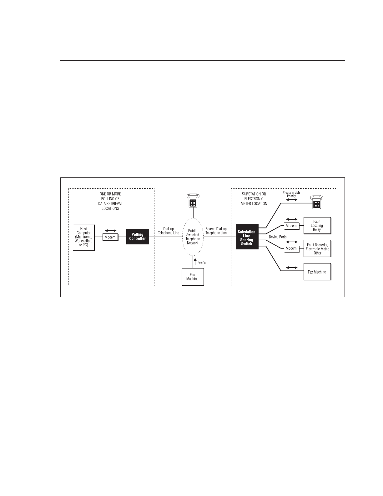
Figure1 illustratesa typical application,in whicha singletelephoneline isshared
by fourdevices.The Polling Controllerisadded to your existinghardware atthe
data retrieval location.
The SLSS offers many benefits, some of which include its ability to:
• Share a single substation telephone line between up to eight devices.
• Eliminate expensive telephone line installation and monthly charges for
briefly used modem lines.
• Ensure correct call routing by using a Polling Controller.
• Enhance worker safety by giving priority to telephone users.
• Hide substation modems from unauthorized access.
• Obtain high reliability and availability with a unit providing C37.90 SWC
protection to attached devices and powered from 42-150 VDC batteries
(“A” and “B” models only) or 90-150VAC (“D” model only) or 90-220VAC
(“E” model only).
40-400-00031, Rev. A Page 3
Figure 1 Typical SLSS Application
Substation Line Sharing Switch
Chapter 3: Installation
CAUTION:
(1) Never install telephone wiring during a lightning storm.
(2) Never install telephone jacks in wet locations unless the jack is specifically designed for wet locations.
(3) Never touch uninsulated telephone wires or terminals unless the telephone line has been disconnected
at the network interface.
(4) Use caution when installing or modifying telephone lines.
Are You Ready?
Check that you have:
❑ Received an SLSS model M-395-A,B, D, E, M-396-A, B, D, or E. (The model
number is printed on the back of the unit.) Models ending in “-B , -D, or
-E” have the Auxiliary Relay.
❑ Received an Installation Kit which includes: two mounting brackets, two
tie cables, four pan-head slotted screws, four #12 flat washers, four #12
washer locks, four #12 wood screws, and four pan-head screws.
❑ Filled out and returned the Product Registration card.
❑ Collected enough standard modular telephone cords to connect the add-on
devices like modems, fax machines, meters, etc. to the SLSS. (The cords are
available as an ordering option.)
Installing the SLSS
Follow the appropriate steps below to wall-mount or mount the SLSS in a
standard 19" equipment rack. The brackets included in the installation kit are
used to mount the SLSS to a wall or to center- or front-mount the SLSS in an
equipment rack.
❑ To mount the SLSS on a wall, remove and discard the lower two center
screws on the SLSS side panels. Connect the short side of the mounting
brackets to the SLSS using the pan-head (round) screws provided. Then,
attach the mounting brackets to the wall with the supplied wood screws.
-or-
❑ To center-mount the SLSS in Equipment Rack, locate the center-most
screw holes and remove the two screws on the SLSS side panels and
discard. Use the pan-head (round) screws in the installation kit to attach
the brackets. Insert the SLSS into the rack and secure it with the provided
screws.
-or-
Page 4
Reference Manual Chapter 3: Installation
❑ To front-mount the SLSS in Equipment Rack, remove the screws below
the threaded insert closest to the front of SLSS. Use the screws provided in
the installation kit to attach the the mounting bracket to the two vertical
holes closest to the SLSS front panel. Install the SLSS in the equipment
rack and secure it with the supplied screws.
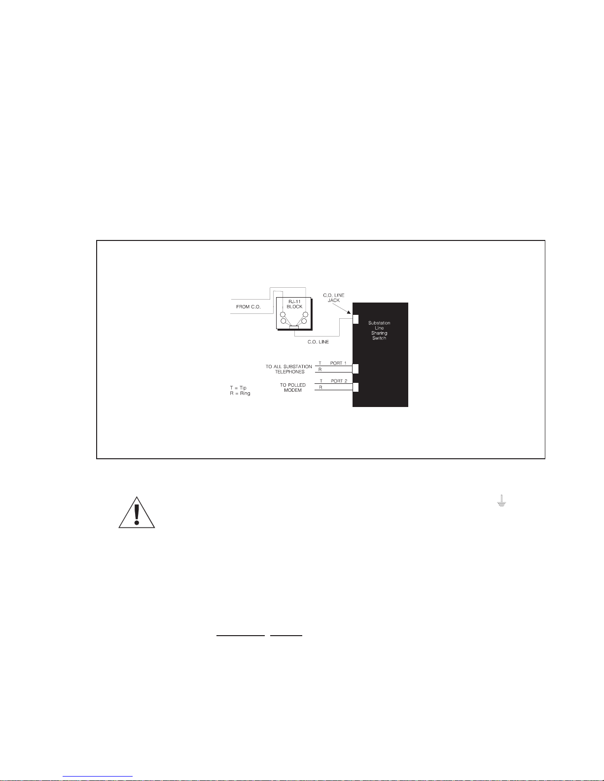
❑ Locate the incoming Central Office telephone (CO) and plug it into the CO
Line jack on the back of the SLSS. (The incoming line comes from the
telephone RJ-11/wall jack.)
❑ Verify that the polarity of the incoming telephone line is correct. For more
detail, see Appendix 2: Troubleshooting.
RT
4
3
4
3
Figure 2 Installing the Central Office Telephone Line
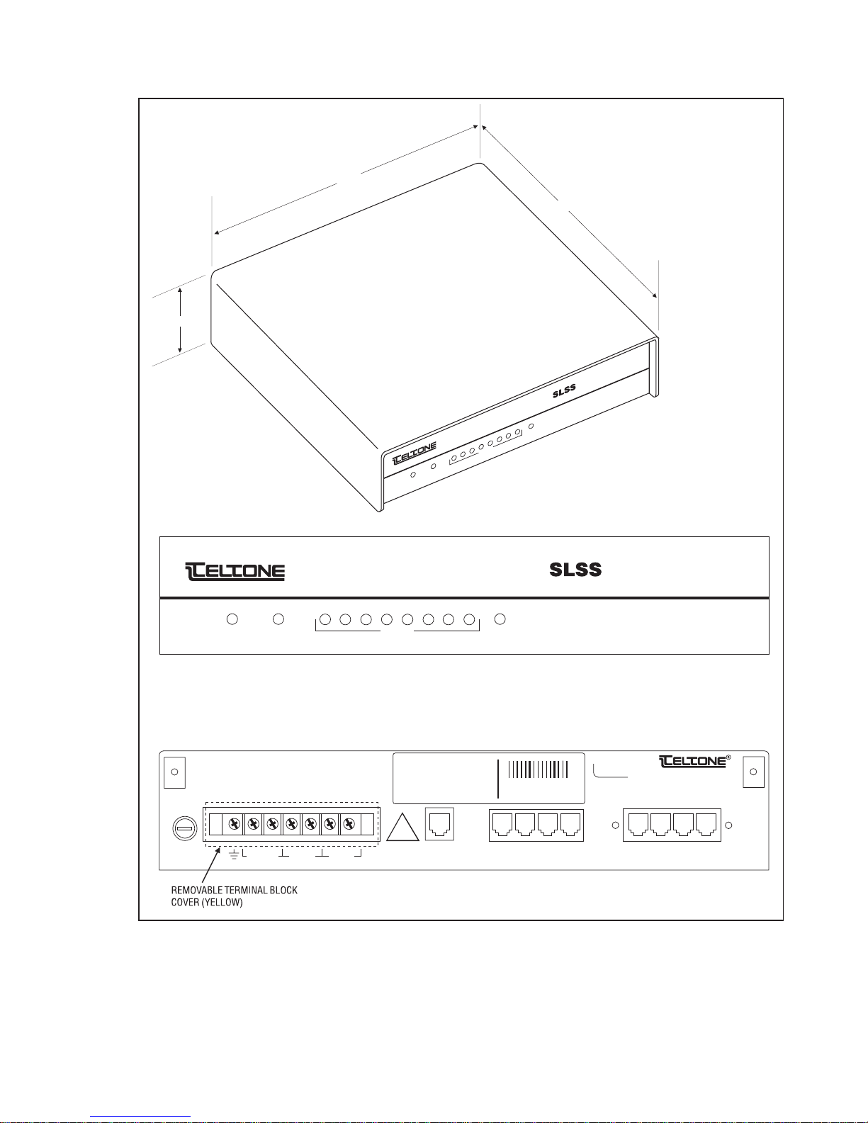
❑ Connect the protective grounding to the screw above this symbol on the
barrier strip on the back of the SLSS. The SLSS must be grounded to operate
properly.
❑ Connect the SLSS to the incoming line in front of any other devices: all
devices that will be used with the SLSS must plug into it.
❑ If there are multiple CO lines, check the telephone numbers assigned to
each line to determine which connects to the SLSS.
❑ Plug a touchtone (DTMF) telephone into Port 1.
❑ Connect other devices (modems attached to fault recorders, meters, etc.) to
any of the other ports with standard telephone cords.
40-400-00031, Rev. A Page 5
Substation Line Sharing Switch
2.37"
12.00"
STATUS
ALARM
11.80"
Substation Line Sharing Switch
8
7
AUX
6
®
5
4
3
2
PORTS
1
STATUS
CAUTION:
FOR CONTINUED PROTECTION
AGAINST RISK OF FIRE,
REPLACE ONLY WITH SAME
TYPE AND RATING OF FUSE.
1.5AMP,
SLO-BLO,
3AG, 250V
FUSE
®
Substation Line Sharing Switch
12345678
ALARM AUXPORTS
SLSS Front Panel
THIS DEVICE COMPLIES WITH PART 15
OF THE FCC RULES. OPERATION IS
SUBJECT TO THE FOLLOWING TWO
CONDITIONS: (1) THIS DEVICE MAY NOT
CAUSE HARMFUL INTERFERENCE, AND
(2) THIS DEVICE MUST ACCEPT ANY
INTERFERENCE RECEIVED, INCLUDING
INTERFERENCE THAT MAY CAUSE
UNDESIRED OPERATION.
MODEL NO.:
UNIT NO.:
PART NO.:
MFG DATE:
WARR DATE:
PATEN 5,241,587
PATENT PENDING
LOAD NUMBER: XX
COMPLIES WITH PART 68, FCC RULES
FCC REG NO.: XXXXXX-XXXXX-XX-X
RINGER EQUIVALENCE: X.XB
!
A1 R1
-
ALARMS AUX42-150 VDC
A2 R2+
C.O.
LINE
SLSS Rear Panel
Figure 3 Substation Line Sharing Switch (M-396-B-01)
PORT
PORT
1
PORT
PORT
2
4
3
PORT
5
Bothell, WA U.S.A.
Made in U.S.A.
PORT
PORT
7
6
PORT
8
Page 6
Reference Manual Chapter 3: Installation
❑ (Optional) Connect alarm monitoring equipment to the internal dry
contact alarm relay terminating at the barrier strip screws labeled A1 and
A2.
❑ For the “A” and “B” models, connect the power (42 - 150 VDC) leads to the
positive (+) and negative (-) screws on the barrier strip on the back of the
SLSS.
❑ For the “D” model, connect the power (90-150 VAC)) leads to the Line (L)
and Neutral (N) screws on the barrier strip on the back of the SLSS.
❑ For the “E” model, connect the power (90-220 VAC)) leads to the Line (L)
and Neutral (N) screws on the barrier strip on the back of the SLSS.
❑ Provide power to the SLSS and check that all LEDs light momentarily. The
Status LED will blink indicating the SLSS is idle. If power is lost to the SLSS,
a direct path between the C.O. Line port and Port 1 is maintained.)
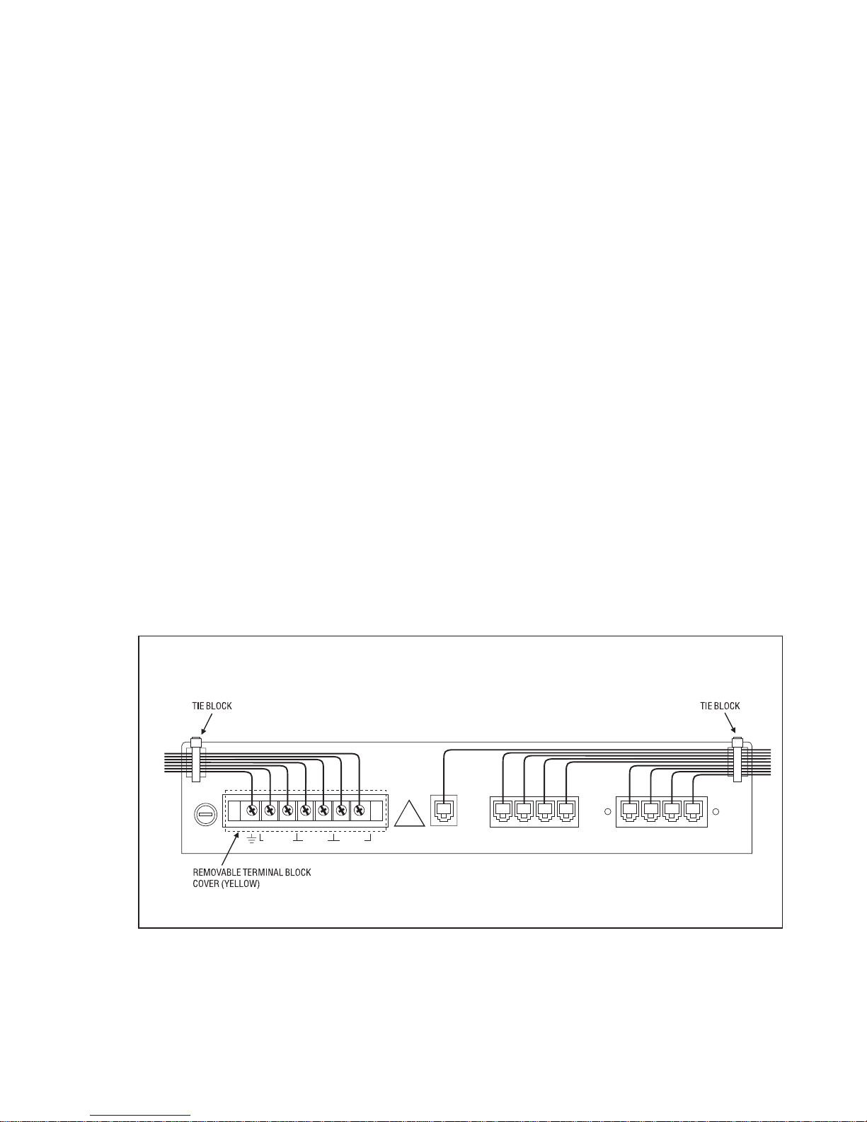
❑ Run the wiring for the terminal block to the left of the unit, through the tie
block. Secure the wires using the “zip” ties.
❑ Replace the yellow terminal block cover.
❑ Run the CO Line and all port cabling to the right, through the tie block.
Secure the wires using the “zip” ties.
Route the wiring as shown to prevent noise on the telephone line.
!
FUSE
A1 R1
-
ALARMS AUX42-150 VDC
A2 R2+
C.O.
LINE
SLSS Rear Panel
PORT
PORT
PORT
PORT
2
1
4
3
PORT
PORT
5
6
PORT
PORT
7
8
40-400-00031, Rev. A Page 7
Figure 4 SLSS Wiring Example

Substation Line Sharing Switch
Install Polling Controller (optional)
If you are using the SLSS with the Polling Controller, follow these steps. These
instructions are repeated in the Po lling Controller Reference Manual,
40-400-00013.These stepsrequireapersonatboth thePolling ControllerandSLSS
locations.
❑ Plug the incoming Central Office telephone line into the Telco Line port on
the back panel of the Polling Controller. (The incoming line comes from the
telephone RJ-11/wall jack.)
❑ Connect another standard modular telephone cord from the modem to the
Modem port on the back of the Polling Controller. (The cords are available
as an ordering option.)
❑ Connect a standard RS-232 cable from the modem to the computer (PC,
mainframe, or workstation) used to control polling.
❑ Connect the PS-24DC-01 power transformer cord to the jack labeled: Class
2 Input Power Pack, on the rear of the Polling Controller. Plug the power
transformer into a 120 VAC outlet.
❑ If you are using multiple Polling Controllers, see the Installing Multiple
Units in Carrier instructions in the Polling Controller Reference Manual
(40-400-00013).
❑ The power LED on the back panel should be flashing. If not, check that the
power is securely connected. (If the LED does not light, check the power
connection and fuse. If the LED is on bright, but does not flash, see the
Troubleshooting instructions in the appendix.)
❑ Place a call to the telephone connected to Port 1 on the SLSS. The call
should be answered by the SLSS on the first ring and the Port 1 telephone
should ring after four seconds. Answer the phone, then hang up.
❑ The system is ready to go to work. To call one of the ports on the SLSS, dial
the SLSS telephone number and add a routing code to the end.
❑ Test that calls are routed properly by plugging a device into Port 3 on the
SLSS, then call the SLSS and enter the routing code for Port 3. Check that
Port 3 rings and that the LED flashes on and off.
❑ Forexample: CallPort 3on theSLSS bydialing 1-206-555-1212∗03from aphone
plugged into the Polling Controller.
❑ Routing codes ∗01-∗08 sends calls to Ports 1-8 as follows: ∗01 routes calls to
Port 1, ∗02 to Port 2, and ∗03 to Port 3, etc.
❑ (Optional.) If you will not be using the default settings, see Programming
Tips in Chapter 4. To program the Polling Controller, refer to the Polling
Controller Reference Manual (40-400-00013).
Page 8

Reference Manual Chapter 3: Installation
Setup Standalone Operation
Follow the steps below to setup the SLSS to work without a Polling Controller.
Note:
the Polling Controller must be re-programmed with transfer codes which
match those of the SLSS.
Remember that if the SLSS will ever work with a Polling Controller,
❑ Disconnect the incoming CO line from the SLSS.
❑ Connect a DTMF telephone to Port 2 of the SLSS.
❑ Pick up the phone and enter # # within 15 seconds.
❑ When you hear the three-beep confirmation tone, enter ∗00#∗02# to
activate the Standalone defaults. Listen for the three-beep confirmation.
❑ Hang up the telephone and reconnect the incoming CO line to the SLSS.
❑ The power LED on the front panel should be flashing. If it is not, check that
the power is securely connected. (If the LED does not light, check the
power connection and fuse. If the LED is on bright, but does not flash, call
Technical Support.)
❑ Call the telephone connected to Port 1. The call should be answered by the
SLSS on the first ring and the Port 1 telephone should ring after four
seconds.
❑ Answer the phone, then hang up.
❑ Now you can call a port on the SLSS by adding the Standalone transfer
codes to the end of the SLSS phone number. (Standalone transfer codes
11-88 access Ports 1-8 as follows: 11 accesses Port 1, 22 accesses Port 2, and
33 accesses Port 3, etc.) See Chapter 4: Changing Transfer Codes to program
new codes.
❑ For example, to call Port 2, dial the SLSS number. Enter 22 after the first ring
(within 4 seconds).
-or-
❑ If you will not be using the Standalone Defaults, review the Programming
Tips in Chapter 4 and follow the Standalone SLSS Programming, also in
Chapter 4.
❑ (Optional) To call through a modem, remember to give the receiving
modem time to answer by adding pause time (,,,,) between the SLSS
telephone number and the transfer code.
If the modem does not answer properly, add or remove commas. If the call
defaults to Port 1, the pause is too long and you should remove one or
more commas. When adding or removing commas, do so one at a time.
40-400-00031, Rev. A Page 9

Substation Line Sharing Switch
The number of commas you will add depends on the time required for the
network to process your call and for the SLSS to answer the call.
❑ For example, to send a call to Port 3, dial: 1-206-555-1212,,,,33
Note:
The guesswork involved in determining the correct number of pauses
is why many users decide to use the Teltone Polling Controller.
❑ (Optional.) Continue to Chapter 4: Programming to review the Programming
Tips before following the Setup for Local, Remote or Standalone
Programming instructions.
Page 10

Reference Manual Chapter 4: Programming
Chapter 4: Programming
Programming Tips
You can adjust or program many of features in the SLSS. All of the options and
commands are listed in Table 2, later in this chapter. The SLSS is programmed
using a touchtone telephone, either locally, without disconnecting the CO Line,
or remotely from the Polling Controller.
Passwords
Always enter # after entering a password. If an invalid password is entered, you
will not hear three beeps and should hang up and wait for 30 seconds before
trying again. If three consecutive invalid attempts are made, the SLSS will lock out all
further access for 1 hour. (M-395-B, D, E models only: If secure relay access is
enabled, the SLSS will allow 5 consecutive invalid attempts.)
Note:
this password.
Remote Programming
Remote Programming must be enabled through Local Programming before you
can access the SLSS remotely. When you have finished programming remotely,
exit by hanging up the telephone. You cannot disable the Remote Programming
feature while in Remote Programming.
ConfirmationTone
When a command has been entered successfully, you will hear a three-beep
confirmation tone after entering the last #.
ErrorTone
When a command has been entered incorrectly, you will hear a single-beep error
tone after entering the last #.
Enable/Disable
With functions that are either enabled or disabled, such as fax routing, an entry
of 0 in the data field disables a feature; 1 enables it.
The password used to access the Auxiliary Relay must be different from
Cancel Command
To canceltheentire command, enter ∗in a command field. To cancel a command,
back to, but excluding the #, enter ∗ in a data field. To abort the entire command,
enter ∗∗ in a data field. If no data is entered in a field, that field is either cleared
or set to zero.
40-400-00031, Rev. A Page 11

Substation Line Sharing Switch
Transfer Codes
When assigning transfercodesfor remote programming or for ports (commands
∗07#n#x# and ∗12#y#n#x#), follow these rules:
• Transfer codes must have the same number of digits, be no more than four digits
long, be unique (i.e., all codes must be different), and can use any of the 16 DTMF
digits.
• If you do not use the defaults, all codes must be programmed in both the
SLSS and Polling Controller.
Entering Programming Commands
You canenter the commands in any order. If you will not use aparticular feature,
skip to the next and continue programming.
Threebeeps tell youthat the SLSSreceivedthe command.One long tonetellsyou
that the command was incorrect and must be entered again. If you make a
mistake, simply re-enter the command correctly.
To enter a command, replace “n,” “x,” and “y” with the desired values.
❑ For example, to change the number of rings before disconnect from 12 to 10,
enter
∗01#10#.
❑ For example, to change the password to 1234, enter ∗03#1234#1234#.
❑ For example, to change the Port 2 transfer code to 8802, enter *12#2#4#8802#
Setup for Remote Programming with a Polling Controller
Note:
Emergency Priority. If one of these priority modes is enabled, Port 1 will be
able to interrupt programming.
The SLSS will exit programming mode and disconnect if 60 seconds elapse
without entry of any digits.
The factory default for Remote Programming is enabled. If you have disabled
Remote Programming, it must be enabled before you can program.
You can access the SLSS for programming from the Polling Controller using a
special transfer code. You must enter a password after entering the Remote
Programming Transfer Code. The transfer code instructs the SLSS to answer
without ringing any of the device ports. Proceed as follows:
Programming may be interrupted if you have enabled Total or
❑ Disconnect the Polling Controller from the host modem.
❑ Plug a DTMF telephone into the Modem port on the Polling Controller.
Page 12

Reference Manual Chapter 4: Programming
❑ Dial the number of the SLSS, adding the #7 routing code to the end of the
number. (This is the Polling Controller default for the Remote
Programming Transfer code.)
❑ When the Polling Controller connects to the switch (you will hear three
beeps and the LED flashes), enter the password within 30
seconds: 8358663# (The default is “Teltone”.)
If an invalid password is entered, there will be no acknowledgment of any
kind. Hang up and wait for 30 seconds before trying again.
❑ When you hear the three-beep confirmation tone, begin programming or
follow the example below. (If you decide to program, please review the
example first.)
Example: Remote Programming with Polling Controller
If you follow the steps in this example, remember to reprogram the settings to
match your application.
❑ Enter ∗50#1# to enable Emergency Priority. When you hear 3 beeps, enter
another command or exit programming mode. If you hear error tone, enter the
command again.
❑ Enter ∗51#1#911#911# to enter the number 911 as the first emergency priority
number. Listen for three beeps.
❑ Enter ∗51#2#18004263926#18004263926# to enter the number 1(800)
426-3926 as the second emergency priority number. Listen for three beeps.
❑ Enter ∗03#8378#8378# to change the password to “test”(8378).Listenfor three
beeps.
❑ Enter ∗06#2# to enable Port 2 to handle fax routing. Listen for three beeps.
❑ Enter ∗09# to exit programming mode. Hang up.
❑ Redial the unit, adding #7 to the end of the number.
❑ Listen for three beeps and watch the LED change, then enter 8378# (test#)
within 30 seconds to check the new password. Listen for three beeps.
❑ Enter *74#1# to enable the Auxiliary Relay. Listen for three beeps.
❑ If you have followed this example and wish to return to the factory defaults, enter
∗00#∗01# Listen for three beeps. Enter *09# and hang up the phone.
-or-
❑ If you wish to use the changes made in this example, enter ∗09# to exit
programming mode.
40-400-00031, Rev. A Page 13
 Loading...