

Page 1

Line Sharing Switch (LSS)
M-392, M-393, and M-394
Product Manual
40-400-00015, Rev. F
Page 2

Note
This manual covers Models M-392-B-01/02, M-393-B-01/02, and M-394-B-01/02.
Copyright Notice
Copyright © 1993 - 2004 Teltone Corporation
All Rights Reserved
Trademarks
Teltone is a registered trademark of Teltone Corporation.
Windows is a registered trademark of Microsoft Corporation.
Other company and product names may be trademarks or
registered trademarks of their respective owners.
Teltone Corporation
Bothell, Washington, USA
Customer Service: 425-951-3388
Technical Support: 425-951-3390
Fax: 425-487-2288
Email: info@teltone.com
Website: www.teltone.com
40-400-00015, Rev. F
Page 3

Reference Manual Contents
Contents
U.S.FCC COMPLIANCE INFORMATION. . . . . . . . . . . . . . . . . . . . . . . . iii
CANADIAN COMPLIANCE. . . . . . . . . . . . . . . . . . . . . . . . . . . . . . . . . . . iv
IMPORTANT SAFETY INSTRUCTIONS . . . . . . . . . . . . . . . . . . . . . . . . . v
SAVE THESE INSTRUCTIONS. . . . . . . . . . . . . . . . . . . . . . . . . . . . . . . . v
About This Manual. . . . . . . . . . . . . . . . . . . . . . . . . . . . . . . . . . . . . . . . . . vi
Conventions Used In This Manual. . . . . . . . . . . . . . . . . . . . . . . . . . . . . . vi
Chapter 1: Getting Started . . . . . . . . . . . . . . . . . . . . . . . . . . . . . . . . . . . . . . . . . . 1
Where to Start . . . . . . . . . . . . . . . . . . . . . . . . . . . . . . . . . . . . . . . . . . . . . 1
Product Registration. . . . . . . . . . . . . . . . . . . . . . . . . . . . . . . . . . . . . . . . . 1
Chapter 2: Overview . . . . . . . . . . . . . . . . . . . . . . . . . . . . . . . . . . . . . . . . . . . . . . . 2
Components. . . . . . . . . . . . . . . . . . . . . . . . . . . . . . . . . . . . . . . . . . . . . . . 2
Figure 1 Typical Application . . . . . . . . . . . . . . . . . . . . . . . . . . . . . . . . . . 2
Programming . . . . . . . . . . . . . . . . . . . . . . . . . . . . . . . . . . . . . . . . . . . . . . 3
Compatibility . . . . . . . . . . . . . . . . . . . . . . . . . . . . . . . . . . . . . . . . . . . . . . 3
Features. . . . . . . . . . . . . . . . . . . . . . . . . . . . . . . . . . . . . . . . . . . . . . . . . . 3
Basic Operation . . . . . . . . . . . . . . . . . . . . . . . . . . . . . . . . . . . . . . . . . . . . 4
Chapter 3: Installing the LSS . . . . . . . . . . . . . . . . . . . . . . . . . . . . . . . . . . . . . . . . 5
Are You Ready?. . . . . . . . . . . . . . . . . . . . . . . . . . . . . . . . . . . . . . . . . . . . 5
LED Indicators . . . . . . . . . . . . . . . . . . . . . . . . . . . . . . . . . . . . . . . . . . . . . 5
Table 1 LED Indicators on the LSS. . . . . . . . . . . . . . . . . . . . . . . . . . . . . 5
Mounting Options. . . . . . . . . . . . . . . . . . . . . . . . . . . . . . . . . . . . . . . . . . . 6
Installing the LSS. . . . . . . . . . . . . . . . . . . . . . . . . . . . . . . . . . . . . . . . . . . 6
Figure 2 Installation Using Jack A. . . . . . . . . . . . . . . . . . . . . . . . . . . . . . 6
Installation on PBX or Key Telephone Systems . . . . . . . . . . . . . . . . . . . 7
Figure 3 LSS Mounted Using Mounting Strap. . . . . . . . . . . . . . . . . . . . . 8
Figure 4 Adhesive Mounting Pads . . . . . . . . . . . . . . . . . . . . . . . . . . . . . 8
Figure 5 Line Sharing Switches . . . . . . . . . . . . . . . . . . . . . . . . . . . . . . . 9
Chapter 4: Teltone Default LSS Operation with Polling Controller . . . . . . . . . . . 10
Programming the LSS . . . . . . . . . . . . . . . . . . . . . . . . . . . . . . . . . . . . . . 15
Using the LSS Programming Commands Table. . . . . . . . . . . . . . . . . . . 15
Table 2 LSS Programming Commands. . . . . . . . . . . . . . . . . . . . . . . . . 16
Table 3 Routing Codes for Polling Controller . . . . . . . . . . . . . . . . . . . . 18
Local Programming . . . . . . . . . . . . . . . . . . . . . . . . . . . . . . . . . . . . . . . . 18
Remote Programming . . . . . . . . . . . . . . . . . . . . . . . . . . . . . . . . . . . . . . 19
Chapter 5: Standalone LSS Operation and Programming . . . . . . . . . . . . . . . . . 20
Figure 5 Standalone Line Sharing Switch . . . . . . . . . . . . . . . . . . . . . . . 21
Using the LSS Programming Commands Table. . . . . . . . . . . . . . . . . . . 25
Table 4 LSS Programming Commands. . . . . . . . . . . . . . . . . . . . . . . . . 26
Local Programming . . . . . . . . . . . . . . . . . . . . . . . . . . . . . . . . . . . . . . . . 28
Remote Programming . . . . . . . . . . . . . . . . . . . . . . . . . . . . . . . . . . . . . . 29
Chapter 6: Advanced Applications . . . . . . . . . . . . . . . . . . . . . . . . . . . . . . . . . . . 30
Cascade Features . . . . . . . . . . . . . . . . . . . . . . . . . . . . . . . . . . . . . . . . . 30
Figure 6 LSS Typical Cascade Application . . . . . . . . . . . . . . . . . . . . . 30
Programming for Cascaded LSS Units . . . . . . . . . . . . . . . . . . . . . . . . . 31
Daisy-chain Operation . . . . . . . . . . . . . . . . . . . . . . . . . . . . . . . . . . . . . . 31
Daisy-chain Features. . . . . . . . . . . . . . . . . . . . . . . . . . . . . . . . . . . . . . . 31
Programming for Daisy-chained LSS Units . . . . . . . . . . . . . . . . . . . . . . 32
Figure 7 Daisy-chain LSS Application . . . . . . . . . . . . . . . . . . . . . . . . . . 32
Table 5 Routing Codes . . . . . . . . . . . . . . . . . . . . . . . . . . . . . . . . . . . . . 33
40-400-00015, Rev. F Pagei
Page 4

Line Sharing Switch
Daisy-chain Remote Programming . . . . . . . . . . . . . . . . . . . . . . . . . . . . 33
Table 6 Remote Programming Daisy-chained LSS Units . . . . . . . . . . . 33
Alternate Telephone Connection . . . . . . . . . . . . . . . . . . . . . . . . . . . . . . 34
Figure 8 Installation Using Jack B. . . . . . . . . . . . . . . . . . . . . . . . . . . . . 35
Chapter 7: Warranty, Troubleshooting, and Technical Support . . . . . . . . . . . . . . 36
Warranty Information . . . . . . . . . . . . . . . . . . . . . . . . . . . . . . . . . . . . . . . 36
Troubleshooting . . . . . . . . . . . . . . . . . . . . . . . . . . . . . . . . . . . . . . . . . . . 36
Technical Support . . . . . . . . . . . . . . . . . . . . . . . . . . . . . . . . . . . . . . . . . 36
Return Procedures. . . . . . . . . . . . . . . . . . . . . . . . . . . . . . . . . . . . . . . . . 37
Appendix 1: Specifications . . . . . . . . . . . . . . . . . . . . . . . . . . . . . . . . . . . . . . . . . 38
Appendix 2: Ordering Information. . . . . . . . . . . . . . . . . . . . . . . . . . . . . . . . . . . . 40
Appendix 3: Glossary . . . . . . . . . . . . . . . . . . . . . . . . . . . . . . . . . . . . . . . . . . . . . 41
Index. . . . . . . . . . . . . . . . . . . . . . . . . . . . . . . . . . . . . . . . . . . . . . . . . . . . . . . . . . 43
Page ii
Page 5

Reference Manual Contents
U.S. REGULATORY COMPLIANCE
FCC Part 68 Notice: To comply with FCC Part 68 regulations, the following requirements must be met:
1. If the telephone company requests information on the equipment connected to their lines, please tell them:
a. the telephone number the equipment is connected to;
b. this equipment operates on standard RJ-11 phone jacks;
c. the FCC registration number;
d. the ringer equivalence number (REN). The REN shows how many devices, such as phones, modems, etc. can be connected to
your line. In most areas, there cannot be more than five devices (i.e., a REN of five) on a phone line. If the REN is exceeded,
then your phone may not ring properly.
NOTE: Items C and D above are found on the label on any Teltone equipment connected to your telephone line.
2. These devices must not be installed on coin-operated telephone lines or party lines.
3. Repair work on this device must be done by Teltone Corporation.
4. If any trouble is experienced with this equipment, the telephone company may request that the customer disconnect the registered
equipment from the telephone line to determine if the registered equipment is malfunctioning and if the registered equipment is
malfunctioning, the use of such equipment shall be discontinued until the problem has been corrected.
FCC Part 15 Class B Notice: This equipment has been tested and found to comply with the limits for a Class B digital device, pursuant to part
15 of the FCC Rules. These limits are designed to pro-vide reasonable protection against harmful interference in a residential installation. This
equipment generates, uses and can radiate radio frequency energy and, if not installed and used in accordance with the instructions, may
cause harmful interference to radio communications. However, there is no guarantee that interference will not occur in a particular installation.
If this equipment does cause harmful interference to radio or television reception, which can be determined by turning the equipment off and
on, the user is encouraged to try to correct the interference by one or more of the following measures:
—Reorient or relocate the receiving antenna.
—Increase the separation between the equipment and receiver.
—Connect the equipment into an outlet on a circuit different from that to which the receiver is connected.
—Consult the dealer or an experienced radio/TV technician for help.
40-400-00015, Rev. F Page iii
Page 6

Line Sharing Switch
CANADIAN REGULATORY COMPLIANCE
Notice: This equipment meets the applicable Industry Canada Terminal Equipment Technical Specifications. This is confirmed by the
registration number. The Industry Canada label or the abbreviation, IC, before the registration number signifies that registration was performed
based on a Declaration of Conformity indicating that Industry Canada technical specifications were met. It does not imply that Industry Canada
approved the equipment. Industry Canada does not guarantee the equipment will operate to the user's satisfaction.
Before installing this equipment, users should ensure that it is permissible to connect it to the facilities of the local telecommunications
company. The equipment must also be installed using an acceptable method of connection. In some cases, the company’s inside wiring
associated with a single line individual service may be extended by means of a certified connector assembly (telephone extension cord). The
customer should be aware that compliance with the above conditions may not prevent degradation of service in some situations.
Repairs to certified equipment should be made by Teltone Corporation.
Any repairs or alterations made by the user to this equipment, or equipment malfunctions, may give the telecommunications company cause to
request the user to disconnect the equipment.
Users should ensure for their own protection that the electrical ground connections of the power utility, telephone lines, and internal metallic
water pipe system, if present, are connected together. This precaution may be particularly important in rural areas.
Caution: Users should not attempt to make such connections themselves, but should contact the appropriate electric inspection authority, or
electrician, as appropriate.
The Ringer Equivalence Number (REN) assigned to each terminal device provides an indication of the maximum number of terminal devices to
be connected to a telephone interface without overloading the interface. The termination on an interface may consist of any combination of
devices subject only to the requirement that the sum of the REN of all devices does not exceed five (5) in most, but not all cases. Check with
your local exchange carrier for the REN limit in your service area. The REN assigned to each device is located on the equipment label.
COMPLIANCE NOTICE: This digital apparatus does not exceed the Class A limits for Radio Noise Emissions set out in the equipment
standard ICES-003 for digital apparatus.
AVIS DE CONFORMATION: Le présent appareil numérique n’émet pas de bruits radioélectriques dépassant les limites applicables aux
appareils numériques de la class A prescrites dans le Règlement sur le brouillage radioélectriques édicté par le ministère des Communications
du Canada.
Page iv
Page 7
Reference Manual Contents
IMPORTANT SAFETY INSTRUCTIONS
When using this product, basic safety precautions, including the following, should always be followed to reduce
the risk of fire, electric shock, and injury to persons.
1. Read and understand all instructions.
2. Follow all warnings and instructions marked on the product.
3. The product should be operated only from the type of power source indicated on the marking label. If you
are not sure of the type of power supply, consult your dealer or local power company. The product is
designed for indoor use only.
4. To reduce the risk of electric shock, do not disassemble the product, but take it to qualified service
personnel when service or repair work is required. Opening or removing covers may expose you to
dangerous voltages or other risks. Incorrect reassembly can cause electric shock when the appliance is
subsequently used.
5. If the product does not operate normally by following the operating instructions, or if the product has been
dropped or the cabinet has been damaged, or if the product exhibits a distinct change in performance, refer
servicing to qualified service personnel.
6. If the product is used in a manner other than specified in this manual, the protection provided by the product
may be impaired.
7. For the purpose of removing power from the product, the power input connector is the main power
disconnect point. Pull the power cord away from the connector to ensure power disconnect.
8. Adequate air flow must be maintained in order for the product to operate correctly. Do not wrap the product
in blankets, paper, or other material that may impede ventilation.
40-400-00015, Rev. F Page v
Page 8

Line Sharing Switch
About This Manual
This manual describes the Teltone®M-392-A/B, M-393-A/B, and M-394-A/B Line Sharing
Switches (LSS). The Polling Controller and one or more LSS units can work together as a
system (U.S.Patent Number 5,241,587) or the LSS can operate separately.
The reference manual, (40-400-00013), accompanying the Polling Controller explains
how to install, program, test, and operate the Polling Controller and should be used in
conjunction with this manual.
Conventions Used In This Manual
Where steps are optional, they are labeled: (Optional). Where you are to choose between
two or more steps, they are separated by:
Each step is accompanied by a check box:
Check the box when you finish the step.
q
Some steps are examples and look like this:
This is an example step.
❑
-or-
Page vi
Page 9

Reference Manual Chapter 1: Getting Started
Chapter 1: Getting Started
Installation and setup may require that a person be on-site with the Polling Controller and
another person on site with the Line Sharing Switch.
Please note that programming of an LSS is not required to operate the LSS .You
should program only if you wish to customize the system for your application.
Where to Start
Review Chapter 2, Overview, then Chapter 3, Installing the LSS, and then select one of
the chapters below to get started.
Chapter 4 - Teltone Default LSS Operation with Polling Controller
M-392-B-02, M-393-B-02, M-394-B-02, M39X-A&5
Chapter 5 - Standalone Operation and Programming
M-392-B-01, M-393-B-01, M-394-B-01, M-39X-A&4
To setup the LSS, follow the instructions in Chapter 3.
•
Note:
the unit to operate with different commands.The factory defaults, which are used until
you program the unit, let you get started and operate the unit immediately.
When you have finished installation and have tested each LSS, you can program
Chapter 6 - Advanced Applications
Multiple Unit
•
This configuration is intended for experienced users only.
install, test, and program new port Transfer Codes.
Follow the instructions to
Product Registration
Fill out the Product Registration card and return it to Teltone Corporation.
40-400-00015, Rev. F Page1
Page 10
Line Sharing Switch
Chapter 2: Overview
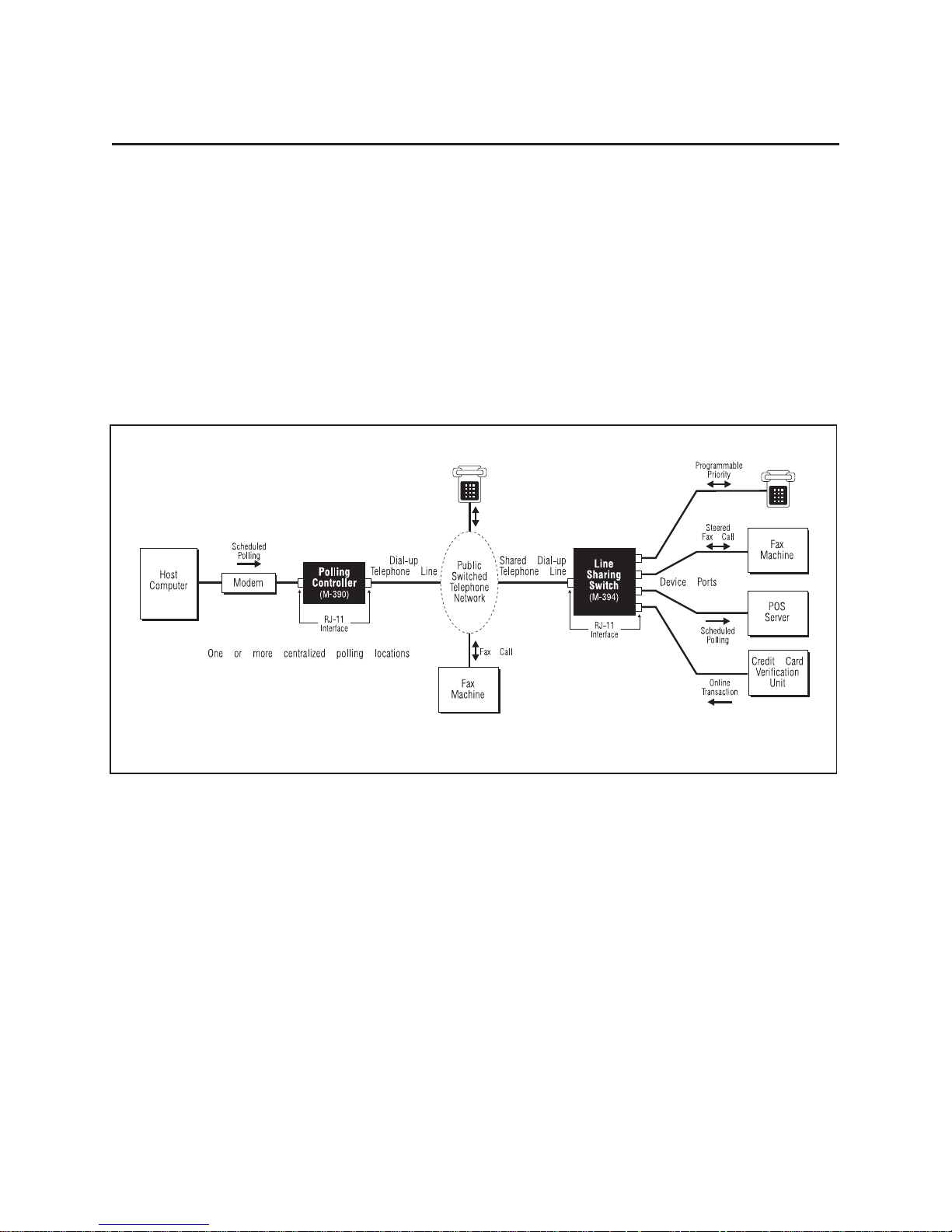
The Teltone Polling Controller and LSSenable businesses using multiple dedicated
telephone lines for short-duration data transfers to save costs through line sharing. In
companies where headquarters regularly poll branch offices for data collection, the
system allows devices, such as modems, to share a phone line at the remote location.
The LSS can also be used by itself, as a standalone unit giving you a flexible,
cost-effective way to consolidate lines.When operating as a standalone unit, calls to the
LSS are routed to the device port without a Polling Controller.
Figure 1 illustrates a typical system application, in which a single telephone line is shared
by four devices: a fax machine receiving automatically routed fax calls, a polled Point of
Sale (POS) server receiving incoming calls, one credit authorization terminal making
outgoing calls, and one telephone for incoming and outgoing calls.
Components
For maximum effectiveness, the Polling Controller and LSS should be used as a system.
The Polling Controller is installed at the central polling location to control access to the
line at the LSS.The LSS is located at the business where lines are being consolidated.
Three versions are available, enabling connection of two, three, or four devices.
The two units communicate across the public switched telephone network (PSTN) to set
up and disconnect calls as well as to determine priorities among devices.
Standalone LSS
If you select this option, the LSS can be used without a Polling Controller to route calls
using standard DTMF codes.Although not required, a Polling Controller is recommended
for data polling applications.
Page 2
Figure 1 Typical Application
Page 11

Reference Manual Chapter 2: Overview
Programming
LSS options are programmed with a DTMF telephone, either locally or remotely from a
Polling Controller.
Compatibility
Any device that can be connected to a standard loop start telephone line, including
telephones, modems, point-of-sale terminals, credit/debit authorization terminals, fax
machines, voice mail systems, answering machines, and others, are compatible with the
Teltone Polling System.These types of telephone lines are also known as Analog Line,
POTS (plain old telephone service) lines, and Single Line Telephone circuits.The LSS will
not operate on digital lines or ground start trunk circuits. The LSS will ring up to five (5)
telephones connected to any single device port.
Note:
single line.
Customer line usage should be analyzed to determine compatible uses for a
Features
Programmable Priority Interrupt
This option enables you to program if and how an on-going call is interrupted for a higher
priority call. The settings are described below:
q
Emergency Priority
telephone matches one of the ten emergency numbers. For example, if you need to
dial 9-1-1, but the line is being used by the fax machine on Port 2, dial 9-1-1 and your
call will be sent through.
q
Total Priority
off-hook. When Total Priority is enabled, Port 2 has priority over Ports 3 and 4, and
Port 3 has priority over Port 4.
Caution:
Priority Mode or Emergency Priority Mode, the LSS will be unable to obtain network dial
tone until the sending fax disconnects or the PSTN
seconds).
q
No Priority
If the LSS is receiving an incoming fax when you go off-hook in either Total
does not allow any emergency call to interrupt an on-going call.
Fax Routing
interrupts an on-going call if the number dialed from the Port 1
gives Port 1, usually a telephone, access to the line whenever it goes
times out (usually within 10-15
This option enables you to route fax calls to a specific LSS port when the LSS detects a
faxing tone.
Remote Programming Access
This option enables you to program the LSS from a remote site.
Programmable Default Port
This option gives you the ability to change the default port to which a call is routed when
no transfer code is provided.This enables you to customize the default ports to match
your application or you can use this feature to prevent default routing.
40-400-00015, Rev. F Page3
Page 12

Line Sharing Switch
Programmable Transfer Codes
This group of features improves security by allowing you to specify the DTMF tones which
route calls at the LSS, ensuring that calls are transferred to the appropriate port. Transfer
codes can be programmed so that the LSS can be used with and without a Polling
Controller in the same application.
Privacy Timeout
When someone takes the telephone off-hook to block incoming telephone calls or when a
device (modem or fax machine) is stuck in an off-hook position, the resulting busy line
prevents incoming calls to all ports.With Privacy Timeout, the LSS will be able to answer
calls and route them to any port, except for the line that is off-hook.
Basic Operation
The LSS answers incoming calls, determines the destination, and routes the call.If a
transfer code is received from a Polling Controller, the LSS routes the call to the
requested device, such as a polled modem.If no transfer code is received, the call is
routed to the default port (Port 1 is the factory default), usually connected to a telephone
(or a telephone and extensions).
When the LSS is used without a Polling Controller, the caller must be sure the LSS
answers the call before sending transfer codes to route the call to a specific port.
An advantage of using the Polling Controller is that the user does not need to generate
the pause time in the dial string between the telephone number and routing code to
accommodate variable switching delays in the network.In addition, the Polling Controller
will hang-up polling calls at the originating end when a priority outbound call is initiated at
the LSS.This latter point means that a caller at the LSS will get faster processing of the
priority call.
Page 4
Page 13
Reference Manual Chapter 3: Installing the LSS
Chapter 3: Installing the LSS
CAUTION:
(1) Never installtelephone wiringduring a lightning storm.
(2) Never installtelephone jacksin wet locations unless thejack is specifically designed forwet locations.
(3) Never touchuninsulated telephonewires or terminals unless thetelephone line has been
disconnected atthe networkinterface.
(4) Use cautionwhen installingor modifying telephone lines.
Are You Ready?
Check that you have:
Line Sharing Switch unit(s)
q
Power Supply - PS-24DC-01
q
Product Registration card (1 for each unit)
q
Mounting equipment: adhesive pads or wall mounting strap. Optional.
q
LED Indicators
An LED power and status indicator is located on the front panel.The LED operates as
described in Table 1.
Table 1 LED Indicators on the LSS
LED Operation Indicates
Slow blink, full/half brightness LSS idle, normal heartbeat
Fast blink, full/half brightness Incoming ring being detected
Slow blink, on/off LSS in service
Fast blink, on/off LSS is generating ringing to a port
Steady on, full brightness, no blink Power present but unit not functioning properly
Connectors
Power and line jacks are located on the back panel.(See Figure 5.) The requirements for
each are listed below:
-
Power:aClass2, 24 VoltDC , 400mApower jack.
Thecenter pinispositive onthisjack. Thetransformeroperates fromstandard120 VAC
wall power. A UL and CSA approved AC to DC transformer is included which converts
the input voltage to the 24 VDC required by the unit.
-
Ports: two, three, or four RJ-11 device ports (models M-392-A/B, M-393-A/B, and
M-394-A/B,respectively).Port1 is thehighest priority deviceport; if atelephone is touse
the lineit shouldbe connected toPort 1.Ports 2 through 4 areinterchangeable and are
used to connect other devices sharing the line.
Useonlywitha Class2 power source.
-
JackA:anRJ-11jackfor connection of theincomingcentraloffice line. Theincomingline
mustbe a standardloopstart line.Any partylineidentification hardwaremust belocated
at the protector block.
-
Jack B: See Chapter 6 for this advanced installation note.
40-400-00015, Rev. FPage5
Page 14
Line Sharing Switch
Mounting Options
The LSS is shipped with adhesive mounting pads, each with adhesive backing for
mounting the unit to a wall or other surface, shown in Figure 4.The LSS may also be
mounted on a wall using mounting strap (UM-110-101), shown in Figure 3 and available
as an ordering option. (See Appendix 2.)
Installing the LSS
The LSS is located at the business or residence where lines are being consolidated.It
must be installed on the
line and all telephones or other devices sharing the line.
Standard modular telephone cords (not supplied) are used for all line connections.
The LSS equipment is intended to be used with Loop Start telephone circuits and
devices, and should
telephone circuits and devices support loop start operation. Please check with your
telephone company, if you are uncertain about your particular telephone circuit.
subscriber side of the demarcation point
not
be used with ground start telephone circuits or devices.Most
, between the incoming
Note:
surge protection device between the unit and the incoming telephone line.
If lightning storms are common in your area, we recommend that you install a
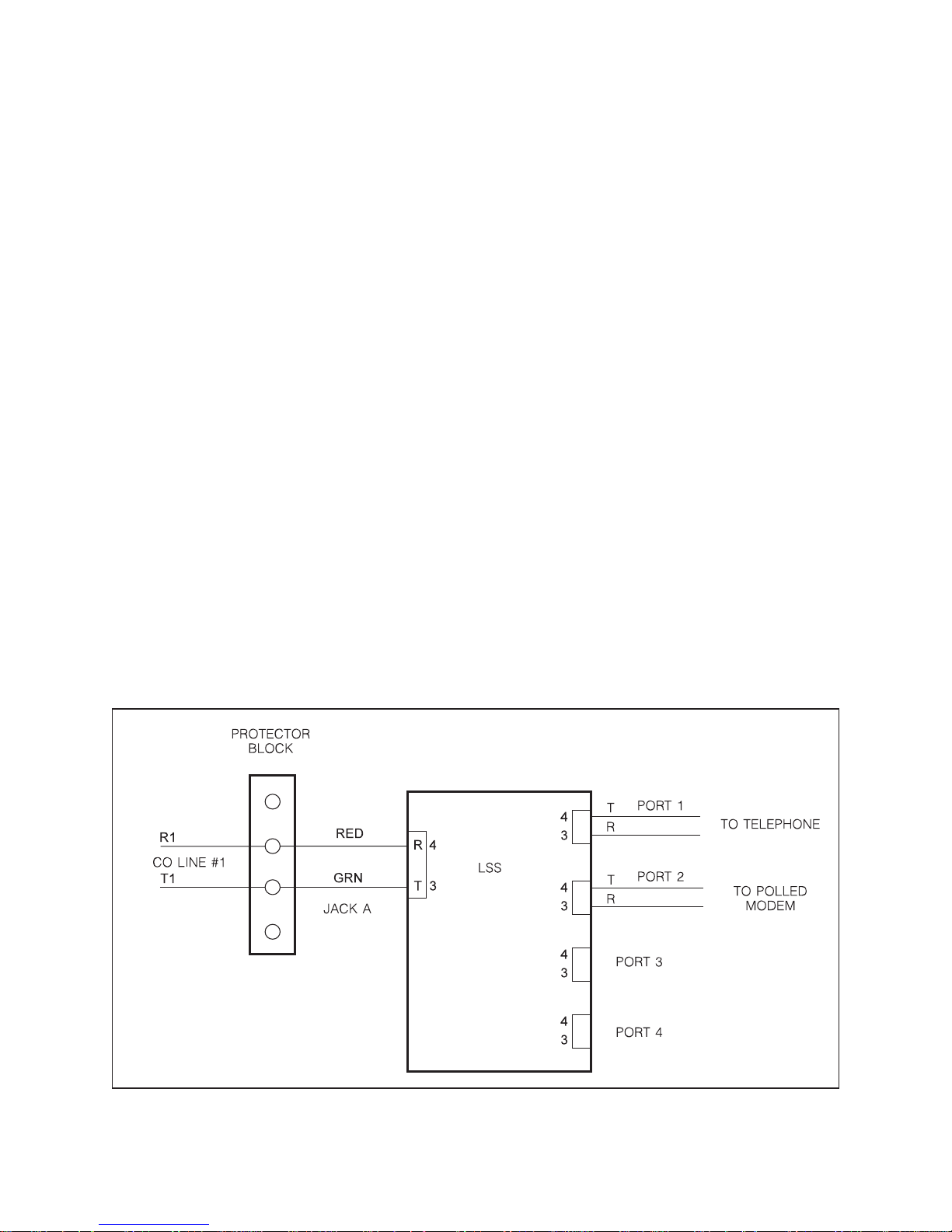
Connect Incoming Line
There are two methods for connecting the incoming telephone line to the LSS.The most
common one uses Jack A.Jack B is used when devices normally connected to Port 1 are
remote from the LSS and you want to use existing wiring.See Chapter 6 for more details.
q Installation Using Jack A: When the LSS is not required in series with the existing
telephone wiring, connect the incoming central office line to Pins 3 and 4 of Jack A.
Page 6
Figure 2 Installation Using Jack A
Page 15

Reference Manual Chapter 3: Installing the LSS
Teltone recommends the use of a standard polarity tester such as Radio Shack
q
43-101. Polarity must be correct on the wiring to the units to minimize relay contact
wear and avoid “bell tap” (a momentary or single ring at the telephone).
Caution: Make sure that the unit is powered down before using the tester.
Plug the tester into the Port 1 jack on the rear panel of the LSS.
q
Check for the following conditions:
If the green light on the tester comes on, the polarity of the wiring is correct.
q
If the red light comes on, Tip and Ring are reversed and must be swapped.
q
If no light comes on, the central office Tip/Ring loop is open.
q
Connect a telephone that is to share the line (if any) to Port 1. (If desired, connect an
q
answering machine to Port 1 and the telephone to the answering machine.) Go
off-hook on the phone and verify dial tone.
Connect other devices that will share the line to the remaining device ports (Port 2 on
q
M-392-A/B; Ports 2 and 3 on M-393-A/B; Ports 2, 3, and 4 on M-394-A/B)
Connect the power cord to the Power jack on the LSS and the transformer to a
q
non-switched, standard AC wall outlet.
The indicator light on the front panel should be flashing. If it is not on, check that the
q
power cord is securely connected and that the outlet has power. If the LED is on
bright, but does not flash, the unit is probably faulty and should be replaced.
q Place a call to the telephone connected to Device Port 1. The call should be
answered on the first ring and the Port 1 telephone should ring after four seconds.
Answer the phone, then place the phone back on-hook.
q Go off-hook on one of Ports 2 through 4 and then attempt to place a call from Port 1.
The Port 1 telephone will not seize the line unless the Total Priority feature has been
enabled. (Teltone Factory Default is No Priority.) Port 1 callers hear busy tone.
q
If a Polling Controller has been installed, place a call from the Polling Controller to
each of the other device ports and verify that the call is routed appropriately.
Installation on PBX or Key Telephone Systems
The LSS can be installed on the telephone company central office side, or trunk side, of a
PBX or Key Telephone System.The LSS can also be installed on the station side or as
an extension on a PBX or Key Telephone System, as long as the interface in an analog
loop start circuit.
For best results in trunk installation, install the LSS in series with the lowest priority
incoming line in a PBX or Key Telephone System hunt group.
Calls intended for devices attached to the LSS must be dialed directly to the telephone
number for this line to prevent misdirected polling or FAX calls.
40-400-00015, Rev. FPage7
Page 16
Line Sharing Switch
Figure 3 LSS Mounted Using Mounting Strap
Apply 2" square dual lock fastening pad to unit
as shown (allow for serial number label).
Both pieces should be mated prior to installation on unit.
Page 8
Figure 4 Adhesive Mounting Pads
Page 17

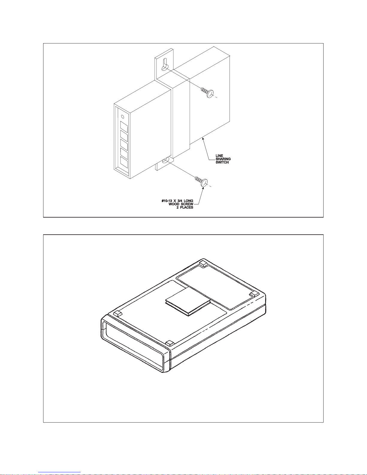
Reference Manual Chapter 3: Installing the LSS
40-400-00015, Rev. F Page 9
Figure 5 Line Sharing Switches
Page 18

Line Sharing Switch
Chapter 4: Teltone Default LSS Operation with Polling Controller
This chapter is used for M-39X-B-02 models only.
Example:
typical polling call from a host computer would progress as described below.
The host modem dials the polling call to access a modem on Port 3 of the remote LSS,
by dialing: 1-206-555-1212*03
The Public Switched Telephone Network (PSTN) processes the call and rings the remote
LSS.
As soon as the Polling Controller recognizes the *03 as a valid routing code, it splits the
line and puts the calling modem on hold. Then it starts sending a translation of the routing
digits (one to four unpublished DTMF digits).This translation or transfer code, is sent at
regular intervals through the network to the LSS. The transfer code will be sent at regular
intervals during the wait period until the LSS acknowledges receipt or until the calling
modem times out and terminates the call.
The LSS answers the call at the end of the first ring and waits for the programmed
amount of time for a transfer code (you program the length of time that the LSS waits for
the code, but the default is four seconds). The Polling Controller sends the code at regular
intervals to ensure that the LSS recognizes it.If, however, the LSS does not get a transfer
code during the wait period, it rings the default port, which is by default, Port 1.
When the LSS recognizes the valid transfer code for Port 3, it rings Port 3 and sends an
acknowledge tone, a typical modem answer tone, to the Polling Controller, instructing the
Polling Controller to connect the host modem to the line to complete the call.
When the Polling Controller and LSS are working together as a system, a
Note:
remote modems even when no LSS is installed.
When the Polling Controller recognizes the acknowledgment tone, it removes the line split
so that the calling modem will be listening when the receiving modem attached to Port 3
answers the data call.
The modem answer tone is used so that a Polling Controller can be used to dial
At this point, the Polling Controller and LSS have established a path for the data call,
enabling the calling and answering modems to handshake properly.
Programming Transfer Codes
The Polling Controller sends transfer codes to the LSS indicating the port to which calls
should be routed. Calls also can be manually routed to any of the ports using a one- to
four-digit transfer code.Remote programming is also accessed through transfer codes.
Each code can be a maximum of four digits in length and can contain any of the 12
DTMF digits.This option must be programmed on both the Polling Controller and the LSS
before it will be activated.Please refer to the following section.
If you are using the LSS as a standalone unit, the transfer codes can be sent manually
from a DTMF telephone or modem. (See Chapter 5, for more detail.) Individual transfer
codes can have a maximum of four digits and can contain any of the 12 DTMF digits.
No Default Port
Use this feature in applications where all of the devices connected to the LSS are used
for polling, including Port 1. This feature can program the LSS
not
to route calls lacking
Page 10
Page 19

Reference Manual Chapter 4: Teltone Default LSS Operation with Polling Controller
transfer codes to Port 1. You have the option of disconnecting the call or routing it to
another port.
After receiving the transfer code, the LSS will send a two-digit DTMF signal (#B) to the
Polling Controller, instead of the modem answer tone. If a call lacks a transfer code, it can
be directed to any of the four ports.When the Polling Controller detects the #B message,
it connects to the polling modem. However, if the Polling Controller detects modem
answer tone
sent to Port 1, regardless of this feature.
be programmed in the Polling Controller.)
without
the #B message, it disconnects the call.
(Please note that the corresponding option must
If power is lost, calls will be
Remote Programming
A password-protected remote programming capability is provided.When remote
programming is enabled at the LSS, options can be programmed from the Polling
Controller.The default password can be changed from the Polling Controller.
Loss of Power at the LSS
During a power failure, telephones connected to Port 1 can receive and place calls.No
other features of the LSS are available.Existing Port 1 connections will
by power failure or restoration.
not
be interrupted
Port Access Priority at the LSS
There are certain conditions under which a caller making a priority interrupt at the LSS
may not be able to immediately obtain central office dial tone which enables the priority
call to be processed by the telephone network.The user will experience a dial tone delay
and/or receive a busy signal to indicate that she/he should redial in these instances.
You can establish one of three types of priority which will determine how competing users
at the LSS are given access to the line.This is determined by a programming command,
as described in Chapter 4. The priority modes are:
If Total Priority Mode is enabled, Port 1 (normally a telephone) is given immediate
access to the line whenever the phone goes off-hook.If another port is using the line (for
example, data transfer is taking place), the modem is halted and the line made free for
the telephone user.Port 2 also has priority access over Ports 3 and 4, but not over Port 1;
Port 3 has priority access over Port 4, but not over Ports 1 and 2.
If Emergency Priority Mode is enabled, a Port 1 user is given priority when one of the
programmed emergency numbers is dialed.The LSS can be programmed to allow up to
ten 16-digit numbers.An Access Code can also be programmed to provide emergency
line access to allow any number to be dialed.
In this mode, Port 2 has total priority over Ports 3 and 4. This arrangement allows
time-sensitive credit card verification calls on equipment connected to Port 2 to take
priority over other calls.
Caution: If the LSS is receiving an incoming fax when you go off-hook in either Total
Priority Mode or Emergency Priority Mode, the LSS will be unable to obtain network dial
tone until the sending fax disconnects or the PSTN times out (usually within 10-15
seconds).
If No Priority Mode is enabled, no port can access the line when another port is using it.
40-400-00015, Rev. FPage11
Page 20

Line Sharing Switch
Calling Party Supervision
The U.S.telephone network typically uses Calling Party Supervision. This means that
even though the called party hangs up, they may be reconnected to the calling party
when their phone is taken off-hook again.The calling party must hang up in order for the
called party to be fully disconnected and initiate a new call. The telephone network will
time out and automatically disconnect the call within 5 - 20 seconds, depending on
network design. This will allow the called party to get dial tone when they go off-hook
again.
To circumvent this problem, when the LSS senses a priority interrupt it immediately
signals the Polling Controller to disconnect the original polling call.This procedure
ensures that the user initiating the priority will have access to network dial tone to
complete the priority call. If for any reason the interrupted call cannot be properly
terminated within approximately 5 seconds, a line busy tone is returned to the priority
caller.The caller should then hang up for a few seconds before trying the call again.
Outgoing Calls from the LSS
The LSS allows DTMF and rotary dialing on outgoing calls.
Telephone Calls—Modem or Other Device Idle:
When the LSS is idle, local telephones are connected to a local battery feed.When a
phone goes off-hook, it is switched to the central office line to obtain dial tone.When the
phone goes on-hook, the line is switched back to a local battery feed.
Telephone Calls—Modem Active:
If in Total Priority Mode, and the modem is active, a priority port going off-hook remains
connected to the local battery feed while the LSS disengages the active port. To do this,
the LSS forces the modem on-hook (terminating the modem carrier), then sends a
disconnect command to the Polling Controller and receives acknowledgment that the
Polling Controller has gone on-hook, then goes on-hook towards the central office to
obtain a new dial tone for the calling party.
If in Emergency Priority Mode, and the telephone at Port 1 goes off-hook , it receives
dial tone (generated internally by the LSS). Dialed digits are monitored. If the dialed
phone number does not match the allowed numbers, the existing connection through the
LSS is not interrupted and busy tone is returned to the telephone user.If, however, the
dialed number matches a programmed emergency phone number, data transfer is halted
and the line made free for the telephone user.The LSS then dials the number and
connects you to the central office line.If you enter the special Access Code, the LSS will
connect you to the central office line;when you receive dial tone, dial any number.
Caution: If the LSS is receiving an incoming fax when you go off-hook in either Total
Priority Mode or Emergency Priority Mode, the LSS will be unable to obtain network dial
tone until the sending fax disconnects or the PSTN times out (usually within 10-15
seconds).
If in No Priority Mode, the modem or other device remains active and the line is not
assigned to another port.
If the LSS receives no response from the Polling Controller after three disconnect
commands are transmitted, the LSS goes on-hook toward the central office for several
seconds to obtain a new dial tone for the calling party. Privacy timeout will not be invoked
unless enabled by the user.Read the Privacy Timeout section later in this chapter for
more details.
Page 12
Page 21

Reference Manual Chapter 4: Teltone Default LSS Operation with Polling Controller
Any priority disconnection delay during a polling call will be minimized if the polling
modem “Loss of Carrier” disconnect time delay is set to a minimum acceptable duration.
This duration is called the Modem Disconnect on Loss of Carrier.
Incoming Calls to the LSS
When the LSS is idle, the incoming central office line is disconnected from the internal
phone line.The LSS answers all calls at the end of the first ring period. It then monitors
for a routing code.
The Polling Controller recognizes the routing digits from the polling modem.As an
additional level of security, the Polling Controller converts the received routing digits to a
transfer code for transmission over the network.
If no code is received by the LSS within 4 seconds after answer, ringing voltage is sent to
the programmed default port and audible ringback is sent to the calling party. If the
telephone is not answered in 1 to 30 rings (default programmed to 12 rings) or a forced
Disconnect is received from the central office, the LSS terminates ringing and goes
on-hook toward the central office.
If a transfer code is received, the LSS sends ringing voltage to the appropriate port. The
LSS also generates a modem answer tone toward the Polling Controller, signaling call
progress.When the local modem answers, the LSS connects the local modem to the
central office lines.The Polling Controller then reconnects the polling modem to the
central office line and modem handshake proceeds normally.
Interrupted Incoming Call at the LSS
If a phone goes off-hook on Port 1 before an incoming call has been connected to a port,
the LSS connects Port 1 to the incoming call, and monitors for a DTMF string from the
Polling Controller. If a DTMF transfer code is received, the LSS will split the line.What
happens next depends on which priority interrupt mode has been programmed.
If the LSS is programmed for No Priority, the call will be routed to the appropriate port,
and Port 1 will receive busy tone.
If in Total Priority Mode, the LSS will perform a disconnect sequence as described
previously, and then connect the central office line to Port 1.
If in Emergency Priority Mode, the LSS will provide dial tone to Port 1, and the user
must dial one of the programmed emergency numbers to gain access to the central office
line.The LSS will not route the incoming call to the port selected by the transfer code until
either the caller is denied access due to dialing an invalid number, or 5 seconds after the
last digit dialed. This design will prevent any modem carrier from interfering with a
disconnect sequence if the caller dials a valid emergency number.If a valid emergency
number is dialed, the LSS will perform a disconnect sequence immediately.
If off-hook is detected on a port other than Port 1, before an incoming call rings the LSS,
the incoming call is connected to the port. If the LSS has detected ringing, or has already
answered the incoming call, and any port other than Port 1 goes off-hook, the LSS will
keep the talk path split for 4 seconds while it monitors for CNG tone or a DTMF string
from the Polling Controller. If CNG or the expected DTMF transfer code is received, the
call is handled as described previously in the “Outgoing Calls from the LSS” section.If a
DTMF transfer code is not received, the call is routed to Port 1, and the off-hook port will
be left connected to the local battery feed. No tones will be sent to the port.
40-400-00015, Rev. FPage13
Page 22

Line Sharing Switch
Off-hook Timeout at the LSS
Occasionally, a need to set a maximum off-hook time is required. The LSS allows either
no limit or a programmable maximum time of up to 255 minutes per port.After an off-hook
timeout timer expires, the device connected to the port will be sent a forced disconnect
(COD) and the C.O. line will be placed on-hook. This off-hook timeout should be set to
encompass the expected duration of any polling or other call.
Privacy Timeout
When Privacy Timeout is enabled, any port remaining off-hook without dialing or
disconnecting properly, the LSS will connect the device to local battery feed and place the
incoming central office line on-hook to enable other ports to receive calls.This lockout of
an offending port occurs after first detecting
tone or two cycles of either busy or reorder tone during the first 15 seconds of off-hook,
and no DTMF digits and 5 or fewer rotary breaks dialed in 60 seconds.
If dial tone, busy, or reorder were not detected, or dialing was detected, the LSS will
monitor for either a hook-flash or forced disconnect.If a hook-flash or forced disconnect is
then detected, the LSS will re-start the privacy timeout period. No tones are sent to the
off-hook phone.Incoming calls to other ports (transfer code received from the Polling
Controller) are routed appropriately; calls to the off-hook privacy phone are given busy
tone.
at least five seconds of Central Office dial
If the port is returned to on-hook and then goes off-hook later, it will receive central office
dial tone per normal operation.
Page 14
Page 23

Reference Manual Chapter 4: Teltone Default LSS Operation with Polling Controller
Programming the LSS
A number of operating parameters in the LSS can be adjusted by the customer. The
programming options are listed in Table 2.The LSS is programmed using a DTMF
telephone keypad, either locally or remotely.
Command Format
All commands start with * and end with #. # is also used to separate the parts of the
command. In general, the formats are as follows:
*<command>#
*<command>#<x>#
*<command>#<x>#<x>#
(no data entry)
x = (single data field)
x#x = (multiple data fields)
Cancel Command
To cancel the entire command, enter: ∗ in a command field.
To abort the entire command, enter ** in a data field.
If no data is entered in a field, that field is either cleared or set to zero.With
enable/disable functions, an entry of 0 in the data field disables a feature; 1 enables it.
Confirmation Tone
When a command has been successfully entered, a confirmation tone (three short
beeps) is returned to the user.
Error Tone
When a command has been entered incorrectly, an error tone (one long beep) is returned
to the user.
Programming Timeout
Remember:
without entry of any DTMF digits.
the LSS will exit the programming mode and disconnect if 60 seconds elapse
Using the LSS Programming Commands Table
Table 2 outlines the commands and provides information about the valid entries and
factory defaults.We have provided a column (Customer Settings) in which you can enter
your selections as you program the unit.We suggest that you use the column as it can
help you keep track of the unit’s settings.
wish to change them at a later date.
40-400-00015, Rev. FPage15
Please make your entries in pencil, as you may
Page 24

Line Sharing Switch
Table 2 LSS Programming Commands
Command Function Description
(1) When entering a command, replace “x” and “y” with the desired variables.
For example, to change the number of rings before disconnect from 12 to 10, enter *01#10#.
To change the password to 1234, enter *03#1234#1234#.
(2) Three short beeps following a command entry confirms that the command is accepted. One long beep indicates an error.
Restore defaults: Resets unit to default settings,
∗00#∗00#
∗01#x#
∗02#x#
∗03#x#x#
∗04#x#
∗05#x#
∗06#x#
∗09#
∗10#x#
∗20#x#
∗30#x#
∗40#x#
∗11#x#
∗21#x#
∗31#x#
∗41#x#
∗50#x#
∗51#y#x#x#
∗52#x#x#
not Customer Defined Settings. THE COMMAND
MUST BE ENTERED AS SHOWN.
Number of rings: Sets the number of times the
LSS will ring any port before disconnecting.
Remote programming: Enables or disables
remote programming.
Password: Sets the password for both local and
remote programming. THE PASSWORD MUST
BE ENTERED TWICE, AS SHOWN.
Dial tone type: Determines the type of dial tone
sent by the LSS to a user attempting emergency
access. If 0 is selected, the user hears precise
dial tone. If 1 is selected, the user hears stutter
tone, indicating that the user has not reached
central office dial tone.
Privacy timeout: Enables or disables the privacy
timeout feature.
Fax routing: Determines the port to which the
LSS directs a fax call when it receives a CNG
signal.
Exit remote programming.
Off-hook timeout, Port 1: Limits the time allowed
for a single call on Port 1.
Off-hook timeout, Port 2: Limits the time allowed
for a single call on Port 2. (All units)
Off-hook timeout, Port 3: Limits the time allowed
for a single call on Port 3.
Off-hook timeout, Port 4: Limits the time allowed
for a single call on Port 4.
Audible ringback, Port 1: Enables or disables
audible ringback with calls to Port 1.
Audible ringback, Port 2: Enables or disables
audible ringback with calls to Port 2.
Audible ringback, Port 3: Enables or disables
audible ringback with calls to Port 3.
Audible ringback, Port 4: Enables or disables
audible ringback with calls to Port 4.
Priority type: Determines how competing users
will be given access to the line.
Emergency phone numbers: When emergency
priority is enabled, this command sets the phone
numbers to which a Port 1 user is allowed priority
access when the line is in use. Up to 10 numbers
can be programmed. y=1 through 10. x=phone
number (up to 16 digits).
THE PHONE NUMBER MUST BE ENTERED
TWICE, AS SHOWN.
Emergency Access Code: When emergency
priority is enabled, this command sets the Access
Code that a Port 1 user can enter to obtain
access to the line in order to dial any number.
THE ACCESS CODE MUST BE ENTERED
TWICE, AS SHOWN.
Valid entries
(x=/y=/n=)
1-30 12
0=disabled
1=enabled
3-10 digits, any DTMF
digits except #
0=precise
1=stuttered
0=disabled
1=enabled
0=disabled
1-4=ports
0-255 (minutes) 0=disabled
0-255 (minutes) 0=disabled
0-255 (minutes) 0=disabled
0-255 (minutes) 0=disabled
0=disabled
1=enabled
0=disabled
1=enabled
0=disabled
1=enabled
0=disabled
1=enabled
0=total priority
1=emergency
2=no priority
y=1-10
x=phone number
0-16 digits none
Teltone
Default
1=enabled
8358663
“Teltone”
0=precise
0=disabled
2
0=disabled
0=disabled
0=disabled
0=disabled
2=no priority
none
Customer
Settings
Page 16
Page 25

Reference Manual Chapter 4: Teltone Default LSS Operation with Polling Controller
Table 2 LSS Programming Commands
Command Function Description
Delay before routing: Number of seconds
∗70#x#
∗71#x#
∗72#x#
∗73#x#
∗07#n#x#
∗12#n#x#
∗22#n#x#
∗32#n#x#
∗42#n#x#
delayed before routing to default or disconnecting,
if no default is set.
Answer tone: When the LSS answers, a
four-beep confirmation tone is sent, or
four-seconds of dial tone are heard.
Transfer code acknowledge: When a transfer
code is sent, an acknowledge tone will indicate
the type of code. (Use this command when
working with the Polling Controller and LSS.)
Select default port: Sets the default port to
which calls will be routed when they lack a routing
code. When working with the standalone LSS,
this command can be sent without sending
∗72#x#.
Transfer code for remote programming: Sets
the transfer code for remote programming.
Replace n with the number of digits, 0-4. If you
enter 0 remote programming will be disabled.
Valid digits for the transfer code include: 1-9, 0, ∗,
and #. (See Note 1)
Transfer code for LSS Port 1: Sets the transfer
code for Port 1 of the LSS. (See Note 1)
Transfer code for LSS Port 2: Sets the transfer
code for Port 2 of the LSS. (See Note 1)
Transfer code for LSS Port 3: Sets the transfer
code for Port 3 of the LSS. (See Note 1)
Transfer code for LSS Port 4: Sets the transfer
code for Port 4 of the LSS. (See Note 1)
Valid entries
(x=/y=/n=)
x=4-30 seconds 4
0=disable
1=confirm
2=dial tone
0=none
1=modem answer tone
2=DTMF ‘#B’
0=no default port
1-4=port
n= 0-4
x=transfer code
n= 0-4
x=transfer code
n= 0-4
x=transfer code
n= 0-4
x=transfer code
n= 0-4
x=transfer code
Teltone
Default
0
1
1
See Note 2 and
Table 3
See Note 2 and
Table 3
Customer
Settings
Note 1:
All transfer codes must have the same number of digits and must be unique. To
program the codes, you can use any of the 12 DTMF digits (0-9, *, and #).
Note 2:
The Teltone Defaults are proprietary and unpublished and require the use of the
Polling Controller, unless reprogrammed by the user. See routing codes *07 - *0, #7 in
Table 3.
40-400-00015, Rev. FPage17
Page 26

Line Sharing Switch
Table 3 Routing Codes for Polling Controller
Routing Code (DTMF) for
Proprietary Transfer Codes
∗07
∗08
∗09
∗0
#7 Proprietary
Routing Code (DTMF) for
Programmable Transfer Codes
∗01 Programmable 1
∗02 Programmable 2
∗03 Programmable 3
∗04 Programmable 4
#1
Transfer Code LSS port
Proprietary
Proprietary
Proprietary
Proprietary
Programming mode
Transfer Code LSS port
Programmable
Programming mode
1
2
3
4
Local Programming
If a telephone line is NOT connected to Jack A of the LSS:
Connect a DTMF telephone to LSS Port 2.
q
Go off-hook and dial ##
q
q When you hear a confirmation tone (3 short beeps), begin programming.
A telephone line must be connected to Jack A of the LSS:
within 15 seconds
. (No password is required.)
q Connect a DTMF telephone to LSS Port 1
q Go off-hook and dial ##
q
Enter the password within 30 seconds (default 8358663#)
within 15 seconds
.
q When you hear a confirmation tone (3 short beeps), begin programming.
Note:
without entry of any DTMF digits.
If an invalid password is entered, there will be no acknowledgment.The user must
hang-up and wait for 30 seconds before attempting to re-enter the programming access
mode.
The unit will exit the programming mode and disconnect if 60 seconds elapse
Example of a Local Programming Session
❑
Access Programming Mode (see previous section).
❑
Enter *21#0# to disable audible ringback on Port 2. When you hear 3 beeps, you
may enter another command or exit programming mode. If you hear error tone,
re-enter the command.
❑
Enter *50#1#to set emergency priority. Listen for 3 beeps.
❑
Enter *51#1#911#911#to enter the number 911 as the first emergency priority
number. Listen for 3 beeps.
❑
Enter ∗51#2#4871515#4871515# to enter the number 487-1515 as the second
emergency priority number. Listen for three beeps.
❑
Enter *02#1# to enable remote programming. Listen for 3 beeps.
❑
Hang-up the phone to exit the programming mode.
Page 18
Page 27

Reference Manual Chapter 4: Teltone Default LSS Operation with Polling Controller
Remote Programming
Remember:
without entry of any digits.
the LSS will exit the programming mode and disconnect if 60 seconds elapse
Accessing the LSS through a Polling Controller
If remote programming is enabled, you can access the LSS for programming using a
Polling Controller, as well as a password. The Polling Controller instructs the LSS to
answer without ringing any of the device ports. Proceed as follows:
Example of a Remote Programming Session
Connect a DTMF telephone to the auxiliary port of the modem connected to the
❑
Polling Controller, or unplug the modem connection to the Polling Controller and
replace it with a DTMF telephone.
Dial the number of the LSS to be programmed and append #7 immediately after
❑
the dialed number.
When the LSS recognizes the programming transfer code, you will hear 3 beeps.
❑
Enter the password within 30 seconds. The default password is: 8358663#
Note:
If an invalid password is entered, there will be no acknowledgment of any kind. The user
must hang up and wait for 30 seconds before attempting to re-enter the programming
access mode.
Always terminate a password entry with #.
❑ When you hear a confirmation tone (3 short beeps), begin programming.
Caution:
LSS will lock out all further access for 1 hour.You cannot disable the Remote
Programming feature while in Remote Programming mode.
❑
❑
❑
❑
❑
❑
❑
❑
If three consecutive and invalid programming access attempts are made, the
Enter *50#1# to set emergency priority. When you hear 3 beeps, you may enter
another command or exit programming mode. If you hear error tone, re-enter the
command.
Enter *51#1#911#911# to enter the number 911 as the first emergency priority
number. Listen for three beeps.
Enter *51#2#18004263926#18004263926# to enter the number 1(800) 426-3926
as the second emergency priority number. Listen for three beeps.
Enter *03#8378#8378# to change the password to “test” (8378). Listen for 3
beeps.
Enter *06#4# to change the fax routing to Port 4. Listen for 3 beeps.
Enter *09# to exit programming mode. Listen for 3 beeps and hang up.
Redial the unit and append #1 immediately. When the Polling Controller connects
to the switch (you will hear a click and the LED changes modes), enter test#
(8378#) within 30 seconds to check the new password. Listen for 3 beeps.
Enter *09# to exit programming mode. Listen for 3 beeps and hang up.
40-400-00015, Rev. FPage19
Page 28

Line Sharing Switch
Chapter 5: Standalone LSS Operation and Programming
This chapter is used for M-39X-B-01 models only.
The LSS can be used with or without the Polling Controller. In this Standalone mode, the
modem or fax dialing string must be programmed to direct calls to assigned ports.(For
example, in Figure 6, modem calls to the POS server would be sent to Port 3 and fax
calls to Port 2.) The LSS can have two, three, or four ports.
Example: A typical polling call from the host computer to a Standalone LSS would
progress as described below.
The host modem dials the polling call to access a modem on Port 3 of the remote LSS.
The host modem dials: 206-487-1515 ,,,,33
Note:
LSS has time to answer before the transfer code, 33, is sent. (The number of pauses
depends on the amount of time that the PSTN takes to ring the LSS and for the LSS to
answer the call after the first ring.) The 33 assumes that you have programmed the LSS
so that 33 is the code to transfer the call to Port 3. (The default transfer code for
Standalone operation.)
The LSS answers the call at the end of the first ring, then waits a programmable amount
of time (four to 30 seconds, the default is 4 seconds) for a transfer code.If the LSS does
not recognize a transfer code during the wait period, it rings the default port, usually Port
1.
When the LSS recognizes the valid transfer code for Port 3, it sends an acknowledgment
tone (a modem answer tone) to the calling modem and rings Port 3.
Note:
the LSS.(The tone removes the line split at the Polling Controller.) You can program the
LSS so that no acknowledgment tone is sent, a modem answer tone is sent, (default), or
a DTMF command, #B, is sent. If a Polling Controller will never be used to access the
LSS, use the first option (i.e., no acknowledgment tone sent) using programming
Command 72.
At this point, the LSS has established a metallic path between the incoming telephone
line and Port 3 for the data call;the calling and answering modems can now handshake
properly.
The “,,,,” are pauses which must be included in the dial string to ensure that the
The modem answer tone is used in case a Polling Controller occasionally calls
Example: An alternative method of making a data call to a Standalone LSS is described
below.
The host modem dials the polling call to access a modem on Port 3 of the remote LSS,
by dialing: 206-487-1515W,33
Note:
is the default, a three-beep confirmation tone, or four seconds of dial tone.
The dial tone allows the host dial string to include a W indicating a wait for dial tone
before proceeding.This avoids guesswork about the number of “,” pauses to put in the
dial string. Unfortunately, people calling the LSS will also hear the dial tone and must be
instructed to simply wait for the call to ring through to the attached telephone on Port 1.
Page 20
The LSS can be programmed to answer incoming calls with either silence, which
Page 29

Reference Manual Chapter 5: Standalone LSS Operation and Programming
Figure 5 Standalone Line Sharing Switch
Programming Transfer Codes
The Polling Controller sends transfer codes to the LSS indicating the port to which calls
should be routed. Calls also can be manually routed to any of the ports using a one- to
four-digit transfer code.Remote programming is also accessed through transfer codes.
Each code can be a maximum of four digits in length and can contain any of the 12
DTMF digits.
No Default Port
Use this feature in applications where all of the devices connected to the LSS are used
not
for polling, including Port 1. This feature can program the LSS
transfer codes to Port 1. You have the option of disconnecting the call or routing it to
another port.
to route calls lacking
Remote Programming
A password-protected remote programming capability is provided.When Remote
Programming is enabled (default enabled) at the LSS, options can be programmed a
DTMF telephone from a remote site.The default password can be changed from the
remote location using a DTMF telephone.
Loss of Power at the LSS
During a power failure, telephones connected to Port 1 can receive and place calls.No
other features of the LSS are available.Existing Port 1 connections will
by power failure or restoration.
Port Access Priority at the LSS
There are certain conditions under which a caller making a priority interrupt at the LSS
may not be able to immediately obtain central office dial tone which enables the priority
call to be processed by the telephone network.The user will experience a dial tone delay
40-400-00015, Rev. FPage21
not
be interrupted
Page 30

Line Sharing Switch
and/or receive a busy signal to indicate that she/he should redial in these instances.
You can establish one of three types of priority which will determine how competing users
at the LSS are given access to the line.This is determined by a programming command,
as described in Chapter 4. The priority modes are:
If Total Priority Mode is enabled, Port 1 (normally a telephone) is given immediate
access to the line whenever the phone goes off-hook.If another port is using the line (for
example, data transfer is taking place), the modem is halted and the line made free for
the telephone user.Port 2 also has priority access over Ports 3 and 4, but not over Port 1;
Port 3 has priority access over Port 4, but not over Ports 1 and 2.
If Emergency Priority Mode is enabled, a Port 1 user is given priority when one of the
programmed emergency numbers is dialed.The LSS can be programmed to allow up to
ten 16-digit numbers.An Access Code can also be programmed to provide emergency
line access to allow any number to be dialed.
In this mode, Port 2 has total priority over Ports 3 and 4. This arrangement allows
time-sensitive credit card verification calls on equipment connected to Port 2 to take
priority over other calls.
Caution: If the LSS is receiving an incoming fax when you go off-hook in either Total
Priority Mode or Emergency Priority Mode, the LSS will be unable to obtain network dial
tone until the sending fax disconnects or the PSTN times out (usually within 10-15
seconds).
If No Priority Mode is enabled, no port can access the line when another port is using it.
Calling Party Supervision
The U.S.telephone network typically uses Calling Party Supervision. This means that
even though the called party hangs up, they may be reconnected to the calling party
when their phone is taken off-hook again.The calling party must hang up in order for the
called party to be fully disconnected and initiate a new call. The telephone network will
time out and automatically disconnect the call within 5 - 20 seconds, depending on
network design. This will allow the called party to get dial tone when they go off-hook
again.
To circumvent this problem, when the LSS senses a priority interrupt it immediately
signals the Polling Controller to disconnect the original polling call.Standalone users will
not have the benefit of the handshake and disconnect.If priority access to dial tone is
important, it is recommended that a Polling Controller be used. (See ordering information
in Appendix 2.) This procedure ensures that the user initiating the priority will have
access to network dial tone to complete the priority call. If for any reason the interrupted
call cannot be properly terminated within approximately 5 seconds, a line busy tone is
returned to the priority caller. The caller should then hang up for a few seconds before
trying the call again.
Outgoing Calls from the LSS
The LSS allows DTMF and rotary dialing on outgoing calls.
Telephone Calls—Modem or Other Device Idle
When the LSS is idle, local telephones are connected to a local battery feed.When a
phone goes off-hook, it is switched to the central office line to obtain dial tone.When the
phone goes on-hook, the line is switched back to a local battery feed.
Page 22
Page 31

Reference Manual Chapter 5: Standalone LSS Operation and Programming
Telephone Calls—Modem Active
If in Total Priority Mode, and the modem is active, a priority port going off-hook remains
connected to the local battery feed while the LSS disengages the active port. To do this,
the LSS forces the modem on-hook (terminating the modem carrier), then sends a
disconnect command to the Polling Controller and receives acknowledgment that the
Polling Controller has gone on-hook, then goes on-hook towards the central office to
obtain a new dial tone for the calling party. Because a Polling Controller may not be used
in the Standalone mode, a longer delay will occur before Central Office dial tone is seen
by the user.
If in Emergency Priority Mode, and the telephone at Port 1 goes off-hook, it receives
dial tone (generated internally by the LSS). Dialed digits are monitored. If the dialed
phone number does not match the allowed numbers, the existing connection through the
LSS is not interrupted and busy tone is returned to the telephone user.If, however, the
dialed number matches a programmed emergency phone number, data transfer is halted
and the line made free for the telephone user.The LSS then dials the number and
connects you to the central office line.If you enter the special Access Code, the LSS will
connect you to the central office line;when you receive dial tone, dial any number.
Caution: If the LSS is receiving an incoming fax when you go off-hook in either Total
Priority Mode or Emergency Priority Mode, the LSS will be unable to obtain network dial
tone until the sending fax disconnects or the PSTN times out (usually within 10-15
seconds).
If in No Priority Mode, the modem or other device remains active and the line is not
assigned to another port.
If the LSS receives no response from the Polling Controller after three disconnect
commands are transmitted, which is the normal operation in the Standalone mode, the
LSS goes on-hook toward the central office for several seconds to obtain a new dial tone
for the calling party. Privacy Timeout will not be invoked unless enabled by the user.Read
the Privacy Timeout section later in this chapter for more details.
Any priority disconnection delay during a polling call will be minimized if the polling
modem “Loss of Carrier” disconnect time delay is set to a minimum acceptable duration.
This duration is called the Modem Disconnect on Loss of Carrier.
Incoming Calls to the LSS
When the LSS is idle, the incoming central office line is disconnected from the internal
phone line.The LSS answers all calls at the end of the first ring period. It then monitors
for a routing code.
If no code is received by the LSS within 4 seconds after answer, ringing voltage is sent to
the programmed default port and audible ringback is sent to the calling party. If the
telephone is not answered in 1 to 30 rings (default programmed to 12 rings) or a Forced
Disconnect is received from the central office, the LSS terminates ringing and goes
on-hook toward the central office.
If a transfer code is received, the LSS sends ringing voltage to the appropriate port. The
LSS also generates a modem answer tone toward the Polling Host Site, signaling call
progress.When the local modem answers, the LSS connects the local modem to the
central office lines.
Interrupted Incoming Call at the LSS
If a phone goes off-hook on Port 1 before an incoming call has been connected to a port,
40-400-00015, Rev. FPage23
Page 32

Line Sharing Switch
the LSS connects Port 1 to the incoming call, and monitors for a DTMF transfer code
from the host site Polling Controller. If a DTMF transfer code is received, the LSS will split
the line.What happens next depends on which priority interrupt mode has been
programmed.
If the LSS is programmed for No Priority, the call will be routed to the appropriate port,
and Port 1 will receive busy tone.
If in Total Priority Mode, the LSS will perform a disconnect sequence as described
previously, and then connect the central office line to Port 1.
If in Emergency Priority Mode, the LSS will provide dial tone to Port 1, and the user
must dial one of the programmed emergency numbers to gain access to the central office
line.The LSS will not route the incoming call to the port selected by the transfer code until
either the caller is denied access due to dialing an invalid number, or 5 seconds after the
last digit dialed. This design will prevent any modem carrier from interfering with a
disconnect sequence if the caller dials a valid emergency number.If a valid emergency
number is dialed, the LSS will perform a disconnect sequence immediately.
If off-hook is detected on a port other than Port 1, before an incoming call rings the LSS,
the incoming call is connected to the port. If the LSS has detected ringing, or has already
answered the incoming call, and any port other than Port 1 goes off-hook, the LSS will
keep the talk path split for 4 seconds while it monitors for CNG tone or a DTMF string
from the Polling site.If CNG or the expected DTMF transfer code is received, the call is
handled as described previously in the “Outgoing Calls from the LSS” section.If a DTMF
transfer code is not received, the call is routed to Port 1, and the off-hook port will be left
connected to the local battery feed. No tones will be sent to the port.
Off-hook Timeout at the LSS
Occasionally, a need to set a maximum off-hook time is required. The LSS allows either
no limit or a programmable maximum time of up to 255 minutes per port.After an off-hook
timeout timer expires, the device connected to the port will be sent a forced disconnect
(COD) and the C.O. line will be placed on-hook. This off-hook timeout should be set to
encompass the expected duration of any polling or other call.
Privacy Timeout
When Privacy Timeout is enabled, any port remaining off-hook without dialing or
disconnecting properly, the LSS will connect the device to local battery feed and place the
incoming central office line on-hook to enable other ports to receive calls.This lockout of
an offending port occurs after first detecting
tone or two cycles of either busy or reorder tone during the first 15 seconds of off-hook,
and no DTMF digits and 5 or fewer rotary breaks dialed in 60 seconds.
If dial tone, busy, or reorder were not detected, or dialing was detected, the LSS will
monitor for either a hook-flash or forced disconnect.If a hook-flash or forced disconnect is
then detected, the LSS will re-start the privacy timeout period. No tones are sent to the
off-hook phone.Incoming calls to other ports (transfer code received from the Polling
Controller) are routed appropriately; calls to the off-hook privacy phone are given busy
tone.
If the port is returned to on-hook and then goes off-hook later, it will receive Central Office
dial tone per normal operation.
at least five seconds of Central Office dial
A number of operating parameters in the LSS can be adjusted by the customer. The
programming options are listed in Table 2.The LSS is programmed using a DTMF
Page 24
Page 33

Reference Manual Chapter 5: Standalone LSS Operation and Programming
telephone keypad, either locally or remotely.
Command Format
All commands start with * and end with #. # is also used to separate the parts of the
command. In general, the formats are as follows:
*<command>#
*<command>#<x>#
*<command>#<x>#<x>#
(no data entry)
x = (single data field)
x#x = (multiple data fields)
Cancel Command
To cancel the entire command, enter: * in a command field.
To abort the entire command, enter ** in a data field.
If no data is entered in a field, that field is either cleared or set to zero.With
enable/disable functions, an entry of 0 in the data field disables a feature; 1 enables it.
Confirmation Tone
When a command has been successfully entered, a confirmation tone (three short
beeps) is returned to the user.
Error Tone
When a command has been entered incorrectly, an error tone (one long beep) is returned
to the user.
Programming Timeout
Remember:
elapse without entry of any DTMF digits.
the LSS will exit the programming mode and disconnect if 60 seconds
Using the LSS Programming Commands Table
Table 4 outlines the commands and provides information about the valid entries and
Standalone defaults.We have provided a column (Customer Settings) in which you can
enter your selections as you program the unit.We suggest that you use the column as it
can help you keep track of the unit’s settings.
a copy of the table, as you may wish to change them at a later date.
Please make your entries in pencil or make
40-400-00015, Rev. FPage25
Page 34

Line Sharing Switch
Table 4 LSS Programming Commands
Command Function Description
(1) When entering a command, replace “x” and “y” with the desired variables.
For example, to change the number of rings before disconnect from 12 to 10, enter *01#10#.
To change the password to 1234, enter *03#1234#1234#.
(2) Three short beeps following a command entry confirms that the command is accepted. One long beep indicates an error.
Restore defaults: Resets unit to default settings,
∗00#∗00#
∗01#x#
∗02#x#
∗03#x#x#
∗04#x#
∗05#x#
∗06#x#
∗09#
∗10#x#
∗20#x#
∗30#x#
∗40#x#
∗11#x#
∗21#x#
∗31#x#
∗41#x#
∗50#x#
∗51#y#x#x#
∗52#x#x#
not Customer Defined Settings. THE COMMAND
MUST BE ENTERED AS SHOWN.
Number of rings: Sets the number of times the
LSS will ring any port before disconnecting.
Remote programming: Enables or disables
remote programming.
Password: Sets the password for both local and
remote programming. THE PASSWORD MUST
BE ENTERED TWICE, AS SHOWN.
Dial tone type: Determines the type of dial tone
sent by the LSS to a user attempting emergency
access. If 0 is selected, the user hears precise
dial tone. If 1 is selected, the user hears stutter
tone, indicating that she/he has not reached
central office dial tone.
Privacy timeout: Enables or disables the privacy
timeout feature.
Fax routing: Determines the port to which the
LSS directs a fax call when it receives a CNG
signal.
Exit remote programming.
Off-hook timeout, Port 1: Limits the time allowed
for a single call on Port 1. (All units)
Off-hook timeout, Port 2: Limits the time allowed
for a single call on Port 2. (All units)
Off-hook timeout, Port 3: Limits the time allowed
for a single call on Port 3. (M-393-A/B and
M-394-A/B only)
Off-hook timeout, Port 4: Limits the time allowed
for a single call on Port 4.
Audible ringback, Port 1: Enables or disables
audible ringback with calls to Port 1.
Audible ringback, Port 2: Enables or disables
audible ringback with calls to Port 2.
Audible ringback, Port 3: Enables or disables
audible ringback with calls to Port 3.
Audible ringback, Port 4: Enables or disables
audible ringback with calls to Port 4.
Priority type: Determines how competing users
will be given access to the line.
Emergency phone numbers: When emergency
priority is enabled, this command sets the phone
numbers to which a Port 1 user is allowed priority
access when the line is in use. Up to 10 numbers
can be programmed. y=1 through 10. x=phone
number (up to 16 digits).
THE PHONE NUMBER MUST BE ENTERED
TWICE, AS SHOWN.
Emergency Access Code: When emergency
priority is enabled, this command sets the Access
Code that a Port 1 user can enter to obtain
access to the line in order to dial any number.
THE ACCESS CODE MUST BE ENTERED
TWICE, AS SHOWN.
Valid entries
(x=/y=/n=)
1-30 12
0=disabled
1=enabled
3-10 digits, any DTMF
digits except #
0=precise
1=stuttered
0=disabled
1=enabled
0=disabled
1-4=ports
0-255 (minutes) 0=disabled
0-255 (minutes) 0=disabled
0-255 (minutes) 0=disabled
0-255 (minutes) 0=disabled
0=disabled
1=enabled
0=disabled
1=enabled
0=disabled
1=enabled
0=disabled
1=enabled
0=total priority
1=emergency
2=no priority
y=1-10
x=phone number
0-16 digits none
Standalone
Default
1=enabled
8358663
“Teltone”
0=precise
1=enabled
0=disabled
1=enabled
1=enabled
1=enabled
1=enabled
0=total priority
none
Customer
Settings
Page 26
Page 35

Reference Manual Chapter 5: Standalone LSS Operation and Programming
Table 4 LSS Programming Commands
Command Function Description
Delay before routing: Number of seconds
∗70#x#
∗71#x#
∗72#x#
∗73#x#
∗07#n#x#
∗12#n#x#
∗22#n#x#
∗32#n#x#
∗42#n#x#
delayed before routing to default or disconnecting,
if no default is set.
Answer tone: When the LSS answers, a
four-beep confirmation tone is sent, or
four-seconds of dial tone are heard.
Transfer code acknowledge: When a transfer
code is sent, an acknowledge tone will indicate
the type of code. (Use this command when
working with the Polling Controller and LSS.)
Select default port: Sets the default port to
which calls will be routed when they lack a routing
code. When working with the standalone LSS,
this command can be sent without sending
∗72#x#.
Transfer code for remote programming: Sets
the transfer code for remote programming.
Replace n with the number of digits, 0-4. If you
enter 0, remote programming will be disabled.
Valid digits for the transfer code include: 1-9, 0, ∗,
and #. (Note 1)
Transfer code for LSS Port 1: Sets the transfer
code for Port 1 of the LSS. (See Note 1)
Transfer code for LSS Port 2: Sets the transfer
code for Port 2 of the LSS. (See Note 1)
Transfer code for LSS Port 3: Sets the transfer
code for Port 3 of the LSS. (See Note 1)
Transfer code for LSS Port 4: Sets the transfer
code for Port 4 of the LSS. (See Note 1)
Valid entries
(x=/y=/n=)
x=4-30 seconds 4
0=disable
1=confirm.
2=dial tone
0=none
1=modem answer tone
2=DTMF ‘#B’
0=no default port
1-4=port
n= 0-4
x=transfer code
n= 0-4
x=transfer code
n= 0-4
x=transfer code
n= 0-4
x=transfer code
n= 0-4
x=transfer code
Standalone
Default
0
1
1
#1
11
22
33
44
Customer
Settings
Note 1
All transfer codes must have the same number of digits and must be unique. To
program the codes, you can use any of the 12 DTMF digits (0-9, *, and #).
40-400-00015, Rev. FPage27
Page 36

Line Sharing Switch
Local Programming
If the telephone line is NOT connected to Jack A of the LSS:
Connect a DTMF telephone to LSS Port 2.
q
Go off-hook and dial ##
q
When you hear a confirmation tone (3 short beeps), begin programming.
q
A telephone line must be connected to the LSS:
Connect a DTMF telephone to Jack A of the LSS Port 1
q
Go off-hook and dial ##
q
Enter the password within 30 seconds (default 8358663# or “Teltone”).
q
When you hear a confirmation tone (3 short beeps), begin programming.
q
Note:
without entry of any DTMF digits.
If an invalid password is entered, there will be no acknowledgment.The user must
hang-up and wait for 30 seconds before attempting to re-enter the programming access
mode.
The unit will exit the programming mode and disconnect if 60 seconds elapse
within 15 seconds
within 15 seconds
. (No password is required.)
.
Example of a Local Programming Session
❑ Access Programming Mode (see previous section).
❑
Enter *21#0# to disable audible ringback on Port 2. When you hear 3 beeps, you
may enter another command or exit programming mode. If you hear error tone,
re-enter the command.
❑
Enter *50#1# to set emergency priority. Listen for 3 beeps.
❑
Enter *51#1#911#911# to enter the number 911 as the first emergency priority
number. Listen for 3 beeps.
❑
Enter ∗51#2#4871515#4871515# to enter the number 487-1515 as the second
emergency priority number. Listen for three beeps.
❑
Enter *02#1# to enable Remote P. Listen for 3 beeps.
❑
Hang-up the phone to exit the programming mode.
Page 28
Page 37

Reference Manual Chapter 5: Standalone LSS Operation and Programming
Remote Programming
Remember:
without entry of any DTMF digits.
the LSS will exit the programming mode and disconnect if 60 seconds elapse
Example of a Remote Programming Session
Dial the number of the LSS to be programmed and append #1 immediately after
❑
hearing the first ring. The LSS will respond with a short modem answer burst
(default) and then three beeps.
Enter the password within 30 seconds. The default password is: 8358663# If the
❑
LSS accepts this entry as a valid password, it will issue three beeps. You can
begin programming.
Note:
If an invalid password is entered, there will be no acknowledgment of any kind. The user
must hang up and wait for 30 seconds before attempting to re-enter the programming
access mode.
Caution:
LSS will lock out all further access for 1 hour.You cannot disable the Remote
Programming feature while in remote programming mode.
Example of a
Always terminate a password entry with #.
If three consecutive and invalid programming access attempts are made, the
Programming Command Sequence
❑ Enter *50#1# to set emergency priority. When you hear 3 beeps, you may enter
another command or exit programming mode. If you hear error tone, re-enter the
command.
❑
Enter *51#1#911#911# to enter the number 911 as the first emergency priority
number. Listen for three beeps.
❑
Enter *51#2#18004263926#18004263926# to enter the number 1(800) 426-3926
as the second emergency priority number. Listen for three beeps.
❑
Enter *03#8378#8378# to change the password to “test” (8378). Listen for 3
beeps.
❑
Enter *06#4# to change the fax routing to Port 4. Listen for 3 beeps.
❑
Enter *09# to exit programming mode. Listen for 3 beeps and hang up.
❑
Redial the unit and append #1 immediately after hearing the first ring. When the
Polling Controller connects to the switch (you will hear a click and the LED
changes modes), enter test# (8378#) within 30 seconds to check the new
password. Listen for 3 beeps.
❑
Enter *09# to exit programming mode. Listen for 3 beeps and hang up.
Hang up when Transfer Code Absent
To Hang up the LSS if no transfer code is entered, send ## before the timeout period has
elapsed. This function may be useful for telephone callers wanting to avoid extended
ringing at the LSS.
40-400-00015, Rev. FPage29
Page 38

Line Sharing Switch
Chapter 6: Advanced Applications
Cascade operation is linking a series of LSS units together through Port 1 and/or other
ports. In this type of operation, the LSS is capable of supporting much more than the
normal 4 ports. Two typical applications are described in this chapter.The first is a
distributed application using Standalone operation, and the second is a daisy-chain
configuration using Teltone Default operation.
Cascaded units operate just as they would normally, with one exception: Priority
operation via Port 1 must
A input of the cascaded LSS, see Figure 7.Other ports can be used to connect any other
device that would normally be used with a LSS (e.g., modems).
Access to the ports of cascaded units is also slightly different from standard operation. A
standard example for accessing port 3 would be by dialing the telephone number of the
line connected to the C.O. port, and then entering 33 after the first ring. In a cascade
configuration, a delay would be placed after the first port access code, followed by the
port access code of the LSS next in line. For example, a modem dial string would be as
follows:
ATDT 1 201 733 9200,,,,33,,44
always
be connected from port 1 of the primary LSS to the Jack
This would route a caller through port 3 of the primary LSS and to port 4 of the
secondary LSS in cascade.
Cascade Features
All features are available in Cascade operation;however, the function of priority modes
(Total and No Priority) is slightly different.
Page 30
Figure 6 LSS Typical Cascade Application
Page 39

Reference Manual Chapter 6: Advanced Applications
For the following explanation, assume that three LSS units are being cascaded as
indicated in the illustration.
If you assign No Priority (default) to all LSS units, equal access is given to the Central
Office line for all ports.
If you assign Total Priority to the first LSS unit and the LSS connected to Port 1, devices
connected to ports on the first and second LSS will be disconnected if Port 1 goes
off-hook.
Caution: If one of the LSS ports is in use when you go off-hook in Total Priority mode,
the LSS will be unable to obtain network dial tone until the call disconnects or until the
times out (usually within 10-15 seconds).
If you assign No Priority to any of the LSS units, calls will never be interrupted. This
setting is not advised for applications requiring a telephone in emergency situations.
Programming for Cascaded LSS Units
Cascaded LSS units can be programmed either locally or remotely. Follow the
instructions in the programming chapter to program the units locally.
Remote Programming would be accessed using the following example.A modem dial
string would be:
ATDT 1 201 733 9200,,,,33,,#1
This would route a caller through port 3 of the primary LSS and access remote
programming for the LSS connected to port 3 in cascade.Follow the instructions in the
programming chapter to program settings for the features you will use.
Daisy-chain Operation
Daisy-chaining is linking a series of LSS units together through Port 1. In this type of
operation, the LSS units and the Polling Controller work together to route calls.
If you are daisy-chaining the M-394-A/B, the four-port model, up to five LSS units can be
daisy-chained; giving a total of 16 ports.
Daisy-chained units operate just as they would normally, with one exception: Port 1 of the
first LSS is
LSS in the chain can use Port 1 to connect to an emergency telephone.Other ports can
be used to connect any other device that would normally be used with a LSS (e.g.,
modems, fax machines, etc.).
always
used to connect to the next LSS through its CO Line port. The last
Daisy-chain Features
All features are available in D operation with a Polling Controller; however, the function of
priority modes (Emergency, Total, and No Priority) is slightly different.
Note:
daisy-chain applications, refer to the tables in Chapter 4.
For the following explanation, assume that three LSS units are being daisy-chained as
indicated in Figure 8.
40-400-00015, Rev. FPage31
For information on changing the proprietary defaults for transfer codes in
Page 40

Line Sharing Switch
In order to use Emergency Priority, program the last LSS in the chain for Emergency
Priority and all others for Total Priority. The last LSS in the chain will have priority over all
others in the chain. When an emergency call is made, the Total Priority mode of other
units up the chain will cause any call in progress to be terminated. As soon as dial tone
is received from the PSTN, the emergency call will be processed.
If you assign Total Priority to all LSS units in the chain, devices connected to ports on
the first and second LSS will be disconnected if any port on the last LSS goes off-hook.
Caution: If one of the LSS ports is in use when you go off-hook in either Total or
Emergency Priority Mode, the LSS will be unable to obtain network dial tone until the call
disconnects or until the times out (usually within 10-15 seconds).
If you assign No Priority to any of the LSS units, calls will never be interrupted. This
setting is not advised for applications requiring a telephone in emergency situations.
Programming for Daisy-chained LSS Units
Daisy-chained LSS units can be programmed either locally or remotely. After carefully
completing this section, follow the instructions in Chapter 4 or 5 to program the units.
Refer to the Table 5 for programming D applications.
Note: For reference only, Unit 1 is the first LSS in the daisy-chain, Unit 2 is the second,
etc.
Page 32
Figure 7 Daisy-chain LSS Application
Page 41

Reference Manual Chapter 6: Advanced Applications
Table 5 Routing Codes
Routing Code Transfer Code LSS Port
∗01
∗02
∗03
∗04
∗05
∗06
∗07
∗08
∗09
∗10
∗11
∗12
∗13
∗14
∗15
∗16
When assigning transfer codes for remote programming or for ports,
Unit 1 Port 2
Unit 1 Port 3
Unit 1 Port 4
Unit 2 Port 2
Unit 2 Port 3
Unit 2 Port 4
Unit 3 Port 2
Unit 3 Port 3
Unit 3 Port 4
Unit 4 Port 2
Unit 4 Port 3
Unit 4 Port 4
Unit 5 Port 1
Unit 5 Port 2
Unit 5 Port 3
Unit 5 Port 4
all codes must be
unique and must have the same number of digits.
q Select a port on one of the daisy-chained LSS units.
q Choose the routing codes (*01 - *16) that you want associated with that port.
q
Assign a unique transfer code to that port.
q
Fill in the table on the next page by assigning the transfer codes to units and ports.
Daisy-chain Remote Programming
If you are going to use remote programming in a daisy-chain, follow the steps below to
configure the LSS units.
q
Using *07#n#x#, the Transfer Code for Remote Programming command, assign a
different remote programming transfer code to each LSS in the daisy-chain.
q
For your reference, enter the unit number of the LSS in the last column of Table 6.
When assigning transfer codes for remote programming,
and must have the same number of digits.
Table 6 Remote Programming Daisy-chained LSS Units
Transfer Code for
Remote Programming
#1 1
#2 2
#3 3
#4 4
#7 PROPRIETARY 5
Remote Programming Code LSS to be Programmed
all codes must be unique
40-400-00015, Rev. FPage33
Page 42

Line Sharing Switch
After completing the table above, program this information into the Polling Controller,
q
if you are using one, then into the LSS. (Programming instructions for the Polling
Controller are provided in Reference Manual 40-400-00013 .)
The
Example: Table 6....
is complete with Remote Programming Codes and the
number of each LSS in the daisy-chain. As indicated in the table, the Remote
Programming Code for the third LSS is #3.
Example: Table 6 Remote Programming Daisy-chained LSS Units
Transfer Code for
Remote Programming
#1 #1 1
#2 #2 2
#3 #3 3
#4 #4 4
#7 PROPRIETARY 5
Set the Remote Programming Code for each LSS with the appropriate transfer code
q
Remote Programming Code LSS to be Programmed
using the information you entered in the table, above.
Following the example in Table 6, you would program the two-digit code for the
❑
third LSS, by entering: *07#2##3#
After you have programmed each LSS with a Remote Programming Code, follow the
q
instructions in Chapter 4 to program settings for the features you will use.
Alternate Telephone Connection
Note:
q
The incoming line appears on Pins 2 and 5 of modular jacks .The Telephone Line pair
are connected to Pins 3 and 4. The LSS will route the calls it receives from Pins 2 and 5
to other phones on Pins 3 and 4. Refer to Figure 9.
Jack B is available only on M-392-A/B and M-393-A/B LSS units.
Installation Using Jack B: Use Jack B to ensure that the LSS is the first device on
the line. Installing the LSS as the first device forces all calls to be processed through
it before they are sent to other extensions. To do this, the protector block wiring must
be modified, most likely on a block wired after the protector. The incoming tip/ring
pair is moved from the first tip/ring pair (T1/R1) to the second tip/ring pair (T2/R2).
Page 34
Page 43

Reference Manual Chapter 6: Advanced Applications
Figure 8 Installation Using Jack B
40-400-00015, Rev. FPage35
Page 44

Line Sharing Switch
Chapter 7: Warranty, Troubleshooting, and Technical Support
Warranty Information
Teltone warrants this product to be free from defects in material and workmanship for a
period of 30 months, given proper installation and usage.At its sole discretion, Teltone
will repair or replace free of charge any unit found to be defective during the warranty
period. Units found defective beyond the warranty period will be repaired or replaced at a
flat rate.
Troubleshooting
Verify the incoming telephone line is active. Plug a test set into the line and verify dial
q
tone is heard when taken off-hook.
Verify the correct line is connected. Have someone place a call to the line in question
q
and verify the telephone device rings.
Verify that power is connected and the Green LED is blinking mid-full brightness.
q
Verify that all connections are secure and have been tested.
q
Verify that the proper LSS has been ordered, - if your LSS has an &5 or -02 suffix,
q
you should be using a Polling Controller. If your LSS has an &4 or -01 suffix, verify
transfer codes are correct.
q Transformer Faulty?
q Check the pause duration in the dial string before sending the transfer code.
(Standalone.) Too short or too long a duration will fail to transfer a call properly.
q Check Incoming Line Polarity - Incorrect line polarity can degrade the performance of
the LSS and may cause problems with certain modems. To avoid this problem and
maximize performance of the LSS, Teltone recommends use of a line polarity tester.
q
Fax Routing Problems? The incoming fax may be sent manually - consequently no
answer tone is heard by the caller, no CNG tone is seen by the LSS, and the call is
transferred to the default port - Port 1.
Option 1 - change the default port to Port 2. Port 1 is still allowed to make outgoing
calls - incoming calls are sent to the fax machine.
Option 2 - instruct the callers to hit start on their fax machine after dialing the number.
Technical Support
For technical assistance on this product, call Teltone technical support at
425-951-3390 or send an email to support@teltone.com.
The telephone company may ask you to disconnect a
suspect unit from the network until the problem has been corrected or until you are sure
the unit is not malfunctioning.
Page 36
Page 45

Reference Manual Chapter 7: Warranty, Troubleshooting, and Technical Support
Return Procedures
If a unit is found to be defective, contact Teltone customer service to obtain a RMA (Return Material Authorization)
number and shipping instructions. When returning units, provide the following information:
• Unit model number, unit part number, and serial number (obtained from the Unit ID label on the bottom
of the unit).
• Teltone RMA number
• All available fault information
• Complete shipping and billing address
• Repair purchase order
History
Old Part Number New Part Number Programmed
M-392-A&4 M-392-B-01 Standalone Configuration
M-392-A&5 M-392-B-02 Teltone Factory Default
M-393-A&4 M-393-B-01 Standalone Configuration
M-393-A&5 M-393-B-02 Teltone Factory Default
M-394-A&4 M-394-B-01 Standalone Configuration
M-394-A&5 M-394-B-02 Teltone Factory Default
M-39XB-01/02 now supports a hardware modification to improve the ringing circuitry.
40-400-00015, Rev. F Page 37
Page 46

Line Sharing Switch
Appendix 1: Specifications
M-392-A/B, M-393-A/B, and M-394-A/B Line Sharing Switches
Power Requirements
Environmental Requirements
Versions 250-00187-18 or higher
Operating Temperature
Storage Temperature
Versions 250-00187-17 or lower
Operating Temperature
Storage Temperature
Humidity
Incoming Line Ring Detect
Frequency
Voltage
Ringer Equivalence
Incoming Loop Hold Circuit
Local Ring Generator
Ringing frequency Rounded square wave output at 20 Hz
DTMF Receiver Parameters
Jack A
Receive level
Receive timing
Port 1 - 4
Receive level
Loop Current On-Hook/Off-Hook Detection
Forced Disconnect Recognition
Port 1 - 4 Rotary Signaling Detection
% Break
Interdigit Time
Jack A - Rotary Dialing Parameters
Rate
Interdigit time
Local Battery Feed
On-hook voltage
Off-hook local battery
(short circuit loop current)
Call Progress Tone Characteristics
Jack A transmit level
Port 1 - 4 transmit level
Ringback Tone
Busy Tone
Dial Tone
Stuttered Dial Tone
Fast Busy Tone
CNG Tone detection (Fax Port)
receive level
Confirmation Tone
Watchdog Timer/Low Supply Voltage Detector
Indicator Lights
Dimensions/Weight
20 VDC ≤ DC Input ≤ 34 VDC.
Maximum current draw = 500 mA
UL/CSA-recognized supply included with unit.
24 VDC, 120 VAC ± 10 %, 60 Hz, 0.2 A max.
No internal fusing required.
-20°C to +60°C
-40°C to +70°C (upper limit up to 3 days)
0°C to +50°C
-40°C to +60°C (upper limit up to 3 days)
90% maximum non-condensing, relative
Ring trips within 200 mS after end of first ring cycle.
5 to 68 Hz
50 VRMS min
2.0B Max
DC resistance of approximately 240 ohms.
50 VRMS minimum at 5 ringer equivalence
2.0 S on/4.0 S off ± 10%
-10 to -40 dBm
40 mS min
+10 to -20 dBm
Unit detects off-hook when loop current is ≥ 20 mA .
Unit detects on-hook when loop current is≤5 mA.
< 350 mS ± 50 mS
8 - 22 pps
40% to 80%
300 mS min
10 pps 60% break
740 mS ± 5mS
40-52 volts DC.
30 mA maximum
-10 ± 3 dBm (combined) into 900Ω
-18 ± 3 dBm (combined) into 900Ω
440 + 480 Hz 2.0 S on/4.0 S off
480 + 620 Hz, 500 mS on/500 mS off
350 + 440 Hz continuous
1 S delay, 3 bursts 100 mS on/off then continuous
970 Hz ± 10%, 250 mS on/250 mS off
1100 Hz ± 100 Hz
-10 to -45 dBm
2125 ± 25 Hz, -13 dBm into 900Ω
Provided in unit. If the microcontroller does not toggle the watchdog timer for
150 ms, the microcontroller is reset. When on-card 5 volt supply is ≤4.5 volts,
the controller is held reset. Normal phone service is not affected by reset and
exit from reset conditions.
Green power and status indicator.
1.50" H x 5.50"W x 9.00"D, 1 lb. 8 oz.
Page 38
Page 47

Reference Manual Appendix 1: Specifications
Regulatory Compliance
Safety
United States UL 1459
Canada CSA C22.2 No. 225-M90
EMC
United States FCC Part 15, Class B
Telecom
United States FCC Part 68
Certification Number: AHHUSA-73685-KX-N
Canada Industry Canada CS-03
Registration Number: 344 4918 A
FCC and Industry Canada REN 1.2B
40-400-00015, Rev. F Page 39
Page 48

Line Sharing Switch
Appendix 2: Ordering Information
M-390-A-04
M-392-B-01
M-392-B-02
M-394-B-01
M-394-B-02
PS-24DC-01 Power transformer and cord.Converts 120 VAC wall power to 24 VDC. Required for use
UM-110-101 Strap for wall mounting one Line Sharing Switch unit (optional).
CA-7F 7 ft.Modular Telephone Cord (optional)
CA-25F 25 ft. Modular Telephone Cord (optional)
40-400-00015 Spare copy of this manual.
Polling Controller. Includes technical manual 40-400-00013.Order separately either
PS-24DC-01 power transformer with cord (one per unit) or UM-112-801 rack mount shelf
(one for each eight units).
Two-port Line Sharing Switch.Includes technical manual 40-400-00015. Enables two
devices to share one telephone line.Includes AC transformer with cord (PS-24DC-01).
Order -01 if previously ordered &4, -02 if &5.
Four-port Line Sharing Switch. Includes technical manual 40-400-00015.Enables four
devices to share one telephone line.Includes AC transformer with cord (PS-24DC-01).
Order -01 if previously ordered &4, -02 if &5.
with M-390-A unless UM-112-801 is used. One included with each LSS unit.
40-400-00013 Spare copy of the Polling Controller manual
Page 40
Page 49

Reference Manual Appendix 3: Glossary
Appendix 3: Glossary
Many of the terms in this glossary were defined with the assistance of Newton’s Telecom
Dictionary, by Harry Newton.To order a copy, call 1-800-LIBRARY or write to: Telecom
Library Inc., 12 West 21 Street, New York, New York 10010.
2500 set
The standard single-line touch-tone desk telephone.
Abbreviated dialing
A feature of telephone systems that allows a caller to dial one or two digits to place a call.The system translates
the digits to the actual number being called.Also known as “speed dialing”.
Busy Tone
A signal generated by the central office indicating that the line you are calling is busy.
Call Progress Tone
A tone sent from the switch to tell the caller of the progress of the call.Examples are audible ringing, re-order,
busy, timing, etc.
Central Office
Telephone company facility where subscriber’s lines are joined to switching equipment for connecting other
subscribers to each other, locally and long distance.(Also called CO.)
Centrex
Business telephone service offered by a local telephone company from a local central office.Centrex is leased
to businesses as a substitute for a business-owned PBX or key telephone system.
CNG
A calling tone issued by a fax device to inform a terminating point that the incoming call is from a facsimile
machine.
C.O.D
Cutoff On Disconnect. This signal, a momentary break of greater that 800mS, is issued by the Central Office
Switching Equipment to attempt a Forced Disconnect.
dB
A decibel is a unit of measure of signal strength.
DTMF
Dual-tone multi-frequency. Push-button telephone signaling.When you touch a button on a push-button pad, it
makes a tone, actually a combination of two tones, one high-frequency and one low-frequency.
Factory default
A setting programmed by Teltone. You can change this value with one of the programming commands. If
necessary, you can use the Restore Defaults command to return to factory defaults.
Forced disconnect
Method used by the telephone company to clear a line.When the called party goes on-hook, the central office
returns an open (that is, drops loop current) of at least 800 ms to the calling party.This is also known as Calling
Party Control (CPC), or Cutoff on Disconnect (COD).
Ground start
One of two types of switched trunks (outside lines) typically leased from telephone companies, the other type
being “loop start”. A ground start trunk initiates an outgoing trunk seizure by applying a local resistance up to
550 ohms from ground to the tip conductor.
Hacker
A person who tries to break into computer or telephone systems, usually by a series of trial-and-error attempts
to break the password.
40-400-00015, Rev. FPage41
Page 50

Line Sharing Switch
Key telephone system
A telephone system in which the telephones have multiple buttons that permit a user to select outgoing or
incoming central office phone lines directly.
LED or light
Light-emitting diode.A semiconductor diode that emits light when a current is passed through it. Used for status
and information displays on electronic devices.
Loop start
One of two types of switched trunks (outside lines) typically leased from telephone companies, the other type
being “ground start”. A loop start trunk is seized by connecting a low resistance between the tip and ring (both
wires) of the telephone line.
If you need to find out if a line is loop start, call your telephone company.
Off-hook
The telephone is in an off-hook state when the handset is removed from the cradle.A modem or other device is
off-hook when it answers a call or when it seizes a line to initiate a call.
Public Switched Telephone Network (PSTN)
Usually refers to the worldwide telephone network accessible to all those with telephones and access privileges
(i.e., in the U.S., it was formerly called the Bell System network or the AT&T long-distance network.)
Remote
At a location physically removed from the equipment in question, that is, a computer or PBX system that can be
accessed by dialing through the telephone network.
Reorder Tone
A tone that sounds like the busy signal, but is twice as fast.It indicates that all switching paths are busy. If you
hear a reorder or “fast busy”, dial the number again.
Touch-tone
See DTMF.
Page 42
Page 51

Reference Manual Index
Index
!
2500 set............................................................. 41
A
Abbreviated dialing............................................ 41
B
Busy Tone.......................................................... 41
C
Calling Party Control.......................................... 41
Calling Party Supervision............................ 12, 22
Canadian compliance.......................................... iv
Cascaded SLTE
Operation.............................................. 30
Centrex.............................................................. 41
Compatibility ....................................................... 3
Confirmation
in programming.............................. 15, 25
D
Daisy-chained SLSS
Operation.............................................. 31
Defaults
defined.................................................. 41
Dial tone delay on priority interrupt call....... 11, 21
Dual-tone multifrequency................................... 41
Key telephone system........................................ 42
L
LED indicators
Line Sharing Switch................................ 5
Light-emitting diode ........................................... 42
Line Sharing Switch
basic operation ....................................... 4
detailed operation............................... 13,
23
general description ................................. 2
installation..................................... 5, 7, 9
installation testing................................... 7
Manual Transfer Codes.................. 10, 21
No Default Routing......................... 10, 21
ordering information.............................. 40
physical description ................................ 3
programming command format...... 15, 25
programming commands. 15, 16, 25, 26
Remote Programming.................... 11, 21
Transfer Codes...................................... 10
Local programming
Line Sharing Switch....................... 18, 28
Loop start........................................................... 42
Loop Start
installation............................................... 6
E
Emergency priority
defined........................................... 11, 22
detailed operation.......................... 12, 23
Emergency Priority
Daisy-chain........................................... 32
Error Tone................................................... 15, 25
F
FCC compliance ................................................. iii
Forced disconnect.............................................. 41
G
Ground start....................................................... 41
H
Hacker................................................................ 41
I
Industry Canada.................................................. iv
Installation
PBX or Key Telephone Systems............. 7
Using Jack A........................................... 6
Using Jack B......................................... 34
K
Key Systems
installation with ....................................... 7
N
No priority
defined............................................ 11, 22
detailed operation................................. 23
No Priority
Daisy-chain.................................... 31, 32
O
Off-hook timeout at Line Sharing Switch .... 14, 24
On-hook mode................................................... 42
Operation
as a system........................................... 10
Ordering information.......................................... 40
P
Passwords
programming command................. 16, 26
Patent.................................................................. vi
PBX
installation with ....................................... 7
Polarity, line wiring
Line Sharing Switch................................ 7
Polling Controller
basic operation ....................................... 4
detailed operation................................. 13
general description ................................. 2
ordering information.............................. 40
40-400-00015, Rev. FPage43
Page 52

Reference Manual Index
Polling Controller and Line Sharing Switch
general description ................................. 2
Polling System
application............................................... 2
basic operation ....................................... 4
Port access priority at Line Sharing Switch
Dial Tone Delay............................... 11, 21
Port access priority at LSS
Modem disconnect, loss of carrier........ 23
Power loss
at Line Sharing Switch................... 11, 21
Priority Type
Daisy-chain........................................... 32
Priority, emergency
defined........................................... 11, 22
detailed operation.......................... 12, 23
Priority, no
defined........................................... 11, 22
detailed operation................................. 23
Priority, total
defined........................................... 11, 22
detailed operation.......................... 12, 23
Privacy timeout........................................... 14, 24
Privacy timeout at Line Sharing Switch ............. 23
Programming
local, Line Sharing Switch.............. 18, 28
remote, Line Sharing Switch.......... 19, 29
Programming commands
Line Sharing Switch....................... 16, 26
R
Remote.............................................................. 42
Remote programming
Line Sharing Switch....................... 19, 29
Return procedures ............................................ 37
Routing codes for LSS ports.............................. 18
Routing digits received by Polling Controller...... 13
S
Safety information................................................ v
Specifications.............................................. 38, 39
T
Total priority
defined........................................... 11, 22
detailed operation.......................... 12, 23
Total Priority
Daisy-chain.................................... 31, 32
Transfer code from Polling Controller................. 13
W
Warranty information................................... 36, 37
Page 44
 Loading...