

Page 1

Polling Controller
M-390
Product Manual
40-400-00013, Rev. C
Page 2

Note
This manual covers Model M-390-A-04.
Copyright Notice
Copyright © 1993 - 2004 Teltone Corporation
All Rights Reserved
Trademarks
Teltone is a registered trademark of Teltone Corporation.
Windows is a registered trademark of Microsoft Corporation.
Other company and product names may be trademarks or
registered trademarks of their respective owners.
Teltone Corporation
Bothell, Washington, USA
Customer Service: 425-951-3388
Technical Support: 425-951-3390
Fax: 425-487-2288
Email: info@teltone.com
Website: www.teltone.com
40-400-00013, Rev. C
Page 3

Contents
U.S. FCC COMPLIANCE INFORMATION........................ iii
CANADIAN COMPLIANCE ................................... iii
About This Manual ............................................ iv
Conventions Used In This Manual ............................... iv
Chapter 1: Getting Started..............................................1
Where to Start..................................................1
Product Registration ............................................2
Technical Support...............................................2
LED Indicators .................................................2
Table 1: LED Indicators on the Polling Controller...................2
Mounting Options ..............................................3
Compatibility ..................................................3
Figure 1 Polling Controller ......................................4
Chapter 2: Overview ..................................................5
Figure 2 Typical Application.....................................5
Basic Operation.................................................6
Chapter 3: Polling Controller Installation ................................7
Are You Ready? ................................................7
Single Unit Installation..........................................7
Installing Multiple Units in Carrier................................8
Figure 3 Polling Controller Carrier (UM-112-801)...................9
Chapter 4: Programming .............................................. 11
Remote Programming the LSS...................................11
Setup Polling Controller for Programming........................11
40-400-00013,Rev.C Pagei
Page 4

Polling Controller Programming Commands ..................... 12
Table 2: Polling Controller Programming Commands ............. 12
Changing Transfer Codes ...................................... 14
Table 3: Routing Codes for LSS Device Ports...................... 14
Table 4: Transfer Codes for Remote Programming ................. 16
Example: Table 4 Transfer Codes for Remote Programming.......... 16
Table 5: Port Routing Code Defaults............................. 17
Chapter 5: Polling Controller Operation................................. 18
Typical Call Sequence.......................................... 18
Programmable Options ........................................ 19
Chapter 6: Warranty and Return....................................... 23
Chapter 7: Quick Start Guide.......................................... 24
Appendix 1: Specifications............................................ 29
Appendix 2: Ordering Information .................................... 31
Appendix 3: Glossary................................................. 32
Appendix 4: Index ................................................... 35
Page ii
Page 5

U.S. REGULATORY COMPLIANCE
FCC Part 68 Notice: To comply with FCC Part 68 regulations, the following requirements must be met:
1. If the telephone company requests information on the equipment connected to their lines, please tell them:
a. the telephone number the equipment is connected to;
b. this equipment operates on standard RJ11 phone jacks;
c. the FCC registration number;
d. the ringer equivalence number (REN). The REN shows how many devices, such as phones, modems, etc. can be
connected to your line. In most areas, there cannot be more than five devices (i.e., a REN of five) on a phone line.
If the REN is exceeded, then your phone may not ring properly.
NOTE: Items C and D above are found on the label on any Teltone equipment connected to your telephone line.
2. These devices must not be installed on coin-operated telephone lines or party lines.
3. Repair work on this device must be done by Teltone Corporation.
4. If any trouble is experienced with this equipment, the telephone company may request that the customer disconnect
the registered equipment from the telephone line to determine if the registered equipment is malfunctioning and if the
registered equipment is malfunctioning, the use of such equipment shall be discontinued until the problem has been
corrected.
FCC Part 15 Class A Notice (M-390-A only): This equipment has been tested and found to comply with the limits for a
Class A digital device, pursuant to part 15 of the FCC Rules. These limits are designed to provide reasonable protection
against harmful interference when the equipment is operated in a commercial environment. This equipment generates,
uses, and can radiate radio frequency energy and, if not installed and used in accordance with the instruction manual,
may cause harmful interference to radio communications. Operation of this equipment in a residential area is likely to
cause harmful interference in which case the user will be required to correct the interference at his own expense.
CANADIAN REGULATORY COMPLIANCE
Notice: This equipment meets the applicable Industry Canada Terminal Equipment Technical Specifications. This is
confirmed by the registration number. The Industry Canada label or the abbreviation, IC, before the registration number
signifies that registration was performed based on a Declaration of Conformity indicating that Industry Canada technical
specifications were met. It does not imply that Industry Canada approved the equipment. Industry Canada does not
guarantee the equipment will operate to the user's satisfaction. Before installing this equipment, users should ensure that
it is permissible to connect it to the facilities of the local telecommunications company. The equipment must also be
installed using an acceptable method of connection. In some cases, the company’s inside wiring associated with a single
line individual service may be extended by means of a certified connector assembly (telephone extension cord). The
customer should be aware that compliance with the above conditions may not prevent degradation of service in some
situations.
Repairs to certified equipment should be made by Teltone Corporation. Any repairs or alterations made by the user to this
equipment, or equipment malfunctions, may give the telecommunications company cause to request the user to
disconnect the equipment. Users should ensure for their own protection that the electrical ground connections of the
power utility, telephone lines, and internal metallic water pipe system, if present, are connected together. This precaution
may be particularly important in rural areas.
Caution: Users should not attempt to make such connections themselves, but should contact the appropriate electric
inspection authority, or electrician, as appropriate. The Ringer Equivalence Number (REN) assigned to each terminal
device provides an indication of the maximum number of terminal devices to be connected to a telephone interface
without overloading the interface. The termination on an interface may consist of any combination of devices subject only
to the requirement that the sum of the REN of all devices does not exceed five (5) in most, but not all cases. Check with
your local exchange carrier for the REN limit in your service area. The REN assigned to each device is located on the
equipment label.
COMPLIANCE NOTICE: This digital apparatus does not exceed the Class A limits for Radio Noise Emissions set out in
the equipment standard ICES-003 for digital apparatus.
AVIS DE CONFORMATION: Le présent appareil numérique n’émet pas de bruits radioélectriques dépassant les limites
applicables aux appareils numériques de la class A prescrites dans le Règlement sur le brouillage radioélectriques édicté
par le ministère des Communications du Canada.
40-400-00013, Rev. C Page iii
Page 6

Polling Controller Reference Manual
About This Manual
This manual describes the Teltone®M-390-A Polling Controller. The Polling
Controller and one or more Line Sharing Switches work together as a system
(U.S. Patent No. 5,241,587) for periodic data transmission.
The Polling Controller works with the Line Sharing Switch (LSS) in retail
applications and with the Substation Line Sharing Switch in electrical power
utility applications. In this manual, LSS is used to indicate both switches.
The reference manual accompanying the LSS explains how to install, program,
test, and operate the LSS or SLSS and should be used in conjunction with this
manual.
Conventions Used In This Manual
Where steps are optional, they are labeled: (Optional). Where you are to
choose between two or more steps, they are separated by: -or-
Underlined terms in the text are defined in the glossary.
Each step is accompanied by a check box:
❑ Check the box when you finish the step.
Some steps are examples and look like this:
❑ This is an example step.
Page iv
Page 7

Chapter 1: Getting Started
Installation and setup require that a person be on-site with the Polling
Controller and one with the Line Sharing Switch.
Please note that programming is not required to operate the Polling
Controller with the Line Sharing Switch. You should program only if you wish
to customize the system for your application.
Where to Start
Select one of the two configurations below to get started. When you get to the
setup, installation, and programming steps, read all instructions and the
examples thoroughly before you begin.
Line Sharing Switch and Polling Controller Configuration
• To setup the Polling Controller, follow the instructions in Chapter 3, Single
Unit Installation. (These instructions are also in the LSS Reference Manual,
Chapter 2: Polling Controller Installation.)
Chapter 1: Getting Started
• If you are using several Polling Controllers and have purchased a Carrier,
follow Installing Multiple Units in Carrier in Chapter 3.
Note:
Controller, you can program the unit to operate with different commands. The
factory defaults, which are used until you program the unit, let you get started
and operate the unit immediately.
When you have finished installation and have tested each Polling
• (Optional.) To program the Polling Controller, review the commands in
Table 2, then follow the Setup Polling Controller for Programming
instructions in Chapter 4.
You must program if: you have programmed the Line Sharing Switch to use
different Port Transfer Codes or if you will daisy-chain the units.
Daisy-chain LSS Configuration
• This configuration is intended for experienced users only. Follow the
instructions to install, test, and program new Port Transfer Codes.
40-400-00013,Rev.C Page1
Page 8
Polling Controller Reference Manual
Product Registration
Please fill out the Product Registration card and return it to Teltone
Corporation. The information on the card will assist us in providingyou with
Technical Support.
Technical Support
If you experience trouble with the Polling Controller, please contact Teltone
technical support at 425-951-3390.
LED Indicators
A power and status indicator LED is located on the back panel and operates as
described in Table 1.
Table 1 LED Indicators on the Polling Controller
LED Operation Indicates
Slow blink, full/half brightness Unit idle
Slow blink, on/off Unit in service
Steady on with double blink offevery 1.5 sec Unit sending code to LSS
Fast blink on/off Disconnect received from LSS
Steady on, full brightness, no blink Power present but unit not functioningproperly
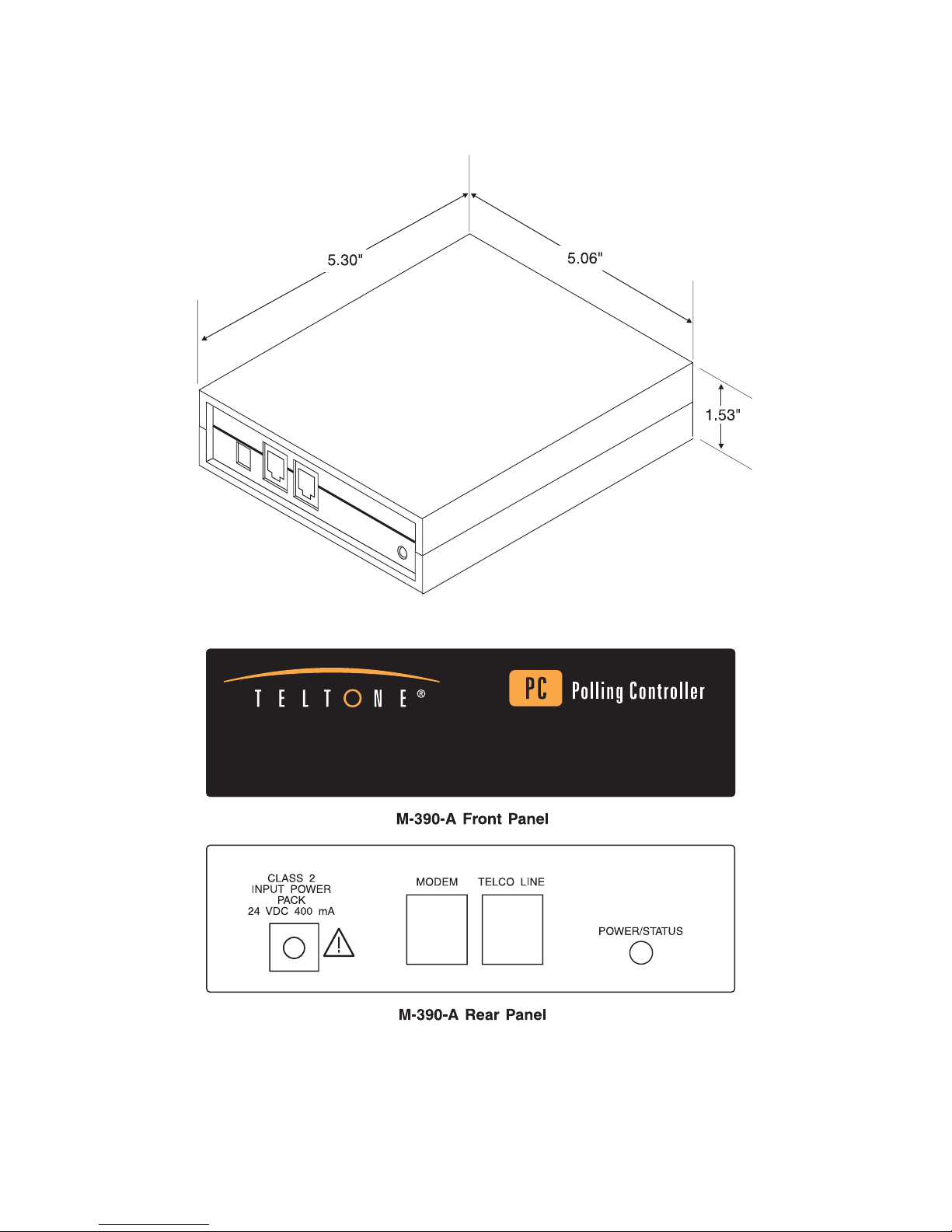
Connectors
All connectors are located on the back panel. Connectors consist of:
- an RJ-11 Central Office (CO) line jack and an RJ-11 Polling Modem line jack
- a Class2, 24 Volt DC,400 mA power jack.Use only with a Class2 power source.
Thecenter pinispositive onthiscoaxial powerjack. Thetransformeroperates
from a standard 120 VAC wall power. A UL and CSA approved AC to DC
transformer converts the input voltage to the 24 VDC required by the unit.
Whenmodules areplacedin acarrier, thesinglein-cable AC-poweredsupply
internaltothe carrier isused sothat a transformerfor eachunitis not required.
Power Loss
While the routing features of the Polling Controller will be disabled if a power
outage occurs, you will be able to make and receive other calls.
Page 2
Page 9

Chapter 1: Getting Started
Mounting Options
The Polling Controller may be placed on a shelf or installed in a Polling
Controller Carrier holding up to eight units. The carrier, shown in Figure 3,
holds the Polling Controller modules in a 19- inch relay rack, in center- or
front-mount positions, and provides power and line connections. A single AC
power cord connects to the internal power supply.
Compatibility
The Polling Controller and LSS are intended for use with Loop Start telephone
lines and devices. The system should not be used with
lines or devices. Most telephone lines and devices support Loop Start
operation. Please check with your telephone company, if you are uncertain
about your particular telephone line.
Ground Start telephone
40-400-00013,Rev.C Page3
Page 10
Polling Controller Reference Manual
Page 4
Figure 1 Polling Controller
Page 11
Chapter 2: Overview
The Teltone®Polling Controller and LSS (Line Sharing Switch or Substation
Line Sharing Switch) enable businesses and utilities having a single telephone
line or those using multiple telephone lines for data transfers to save costs
through line sharing.
Although the LSS can also be used as a standalone unit, providing a flexible,
cost-effective way to consolidate lines and route calls, Teltone strongly
recommends the use of a Polling Controller.
Chapter 2: Overview
When working together, the two units communicate across the
Switched Telephone Network (PSTN) to set up and disconnect calls as well as
to determine priorities among devices and types of calls (e.g., outgoing
emergency calls from the substation take priority over polling calls).
Programming of options in the Polling Controller is done with a
telephone connected to the unit. The LSS can also be remotely programmed
through a touchtone telephone connected to the Polling Controller.
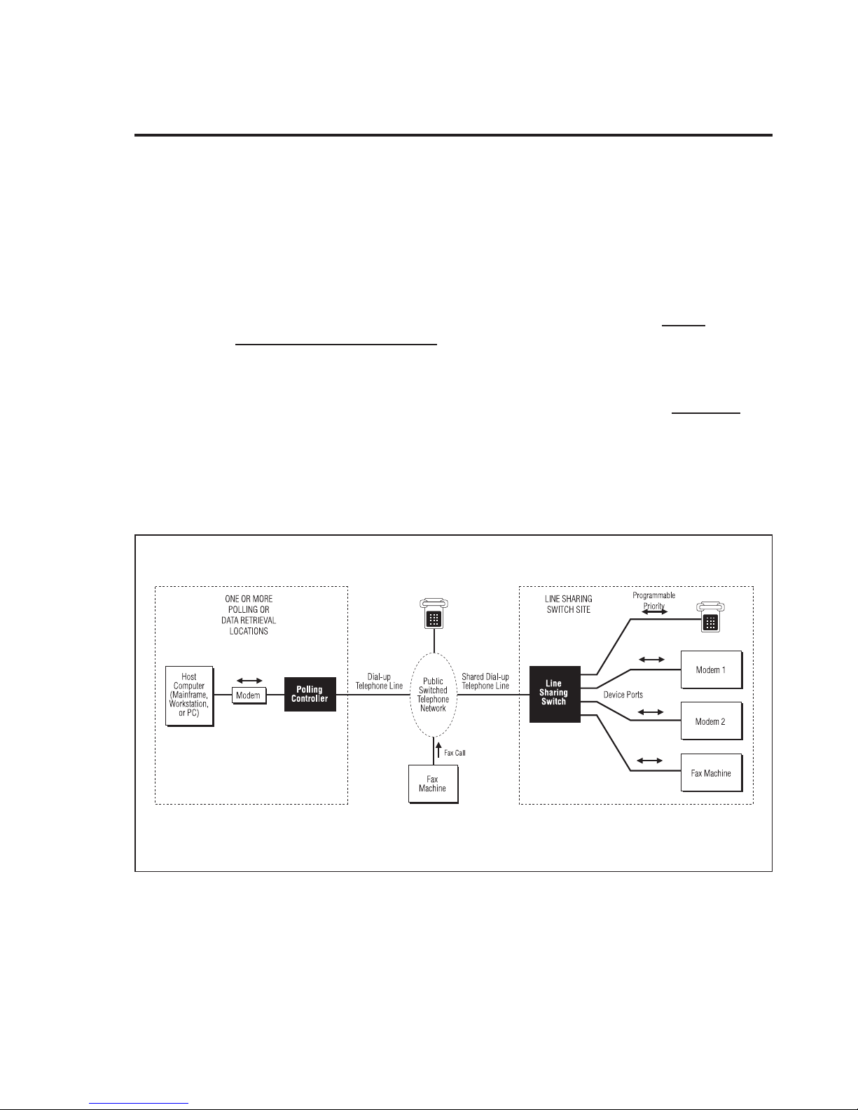
Figure 2 illustrates a typical application, in which a single telephone line is
shared by four devices: two modems, a fax machine receiving automatically
routed fax calls, and one telephone for incoming and outgoing calls.
Public
touchtone
The Polling Controller (Figure 2) is installed at the central polling location to
control how data calls are routed by theLSS.
40-400-00013,Rev.C Page5
Figure 2 Typical Application
Page 12

Polling Controller Reference Manual
Basic Operation
The LSS answers incoming calls, determines the port to which the call should
be sent, and routes the call. If a transfer code is receivedfrom a Polling
Controller, the LSS routes the call to the requested device, such as a polled
modem.
If no transfer code is received, the call is routed to the default port (Port 1 is the
factory default), usually connected to a telephone. However, if no default port
is defined at the LSS, calls without transfer codes are disconnected.
The Polling Controller ensures that the transfer code is sentat the appropriate
time in the dial string. As a result, data calls are routed to the correctport at
the LSS every time, without guesswork about dial string progress. In addition,
the Polling Controller will hang-up polling calls at the originating end when a
priority outbound call is initiated at the LSS. This ensures that a caller at the
LSS will get faster processing of the priority call.
A single Polling Controller can be used to call many LSS units.
The Polling Controller also translates the routing code supplied in the modem
dial string to either a factory set (i.e., unpublished and proprietary) transfer
code, or to a transfer code programmed by the system manager. The
unpublished and programmable transfer code provide added security to your
substation devices by hiding the remote modem from unauthorized access.
Page 6
Page 13
Chapter 3: Polling Controller Installation
Chapter 3: Polling Controller Installation
CAUTION:
(1) Never install telephone wiring duringa lightning storm.
(2) Never install telephone jacks in wet locationsunless the jack is specifically designed forwet locations.
(3) Never touch uninsulated telephone wires or terminalsunless the telephone line has been
disconnected at the networkinterface.
(4) Use caution when installing or modifying telephone lines.
As illustrated in Figure 2, the Polling Controller is installed at the location
from which you originate data calls to the LSS site, between the calling modem
and the telephone line. Use standard modular telephone cords for all line
connections (not supplied). The Polling Controller does not require any change
to your existing hardware.
Please refer to Chapter 2 for interface requirements for the Polling Controller.
Note:
install a surge protection device between the Polling Controller and the
incoming telephone line.
If lightning storms are common in your area, we recommend that you
Are You Ready?
Check that you have:
❑ Polling Controller(s): M-390-A
❑ Product Registration card (1 for each unit)
❑ PS-24DC-01 Power Transformer with cord, 24 VDC (nominal), 400-500 mA
-or-
❑ UM-112-801 Polling Controller Carrier which houses up to 8 M-390-A-04
units (available as an ordering option in Appendix 2)
Single Unit Installation
The following instructions are intended to help you install the Polling
Controller.
Note:
by your PBX or Key system to operate special features. If you have difficulty
using these codes in dialing strings, please contact Teltone Technical Support.
40-400-00013,Rev.C Page7
Be aware that certain dial codes including ∗or# may already be used
Page 14

Polling Controller Reference Manual
Step 1: Connect telephone line
❑ Connect a telephone line to the Polling Controller jack labeled “Telco Line”
using a standard modular cord (not supplied).
Step 2: Verify polarity of CO line wiring
❑ Use a standard polarity tester to check the polarity. Polarity must be
correct on the wiring to the units to minimize relay contact wear and avoid
“bell tap,” a momentary or single ring of the telephone bell.
Caution:
Step 3: Connect modem line
The unit should be powered down whenever you test polarity.
❑ Connect the polling modem to the Polling Controller jack labeled Modem
using a standard modular cord (not supplied).
Step 4: Connect power
❑ Connect the power cord to the Input Power jack on the Polling Controller
and the transformer to a non-switched, standard AC wall outlet.
Step 5: Test the installation
❑ The Power/Status indicator should begin flashing. If it is not on, check that
the power cord is securely connected and that the outlet has power. If the
LED is on bright, but does not flash, call Technical Support for assistance.
❑ After each LSS that will be polled by this unit has been installed, place a
call to each of its device ports and verify that the call is correctly routed. To
access the various LSS ports, refer to Table 3 to determine the routing code,
and enter a dialing string similar to the following:
ATDT4871515
∗02
(With this dial string, the modem calls through the Polling Controller to LSS
Port 2. In this example, the LSS incoming line number is 487-1515.)
Installing Multiple Units in Carrier
The Polling Controller Carrier (model UM-112-801) is used for the installation
of up to eight M-390-A-04 Polling Controller units. See Figure 3. (The carrier is
available as an ordering option.) Follow the steps below to install the carrier
and Polling Controllers:
Step 1: Install carrier in rack
❑ Figure 3 shows mounting brackets attached to the carrier in the position
required to center-mount the carrier in a 19-inch rack. If the carrier is to be
front-mounted, reposition the brackets as appropriate.
Page 8
Page 15

Chapter 3: Polling Controller Installation
❑ Attach the carrier to the rack frame using the screws provided.
Step 2: Make power and line connections to each unit
Complete the following steps for each Polling Controller to be installed:
❑ Insert the unit in any of the eight slots (the slots are interchangeable), with
the power jack towards the bottom and the LED towards the top.
❑ Connect power to each unit installed in the Carrier. (Eight power jacks are
available in the cable trough at the front of the carrier, below the card
slots.)
17.30" MAX
19.00"
18.31"
6.96" MAX
4.00"
POLLING
CONTROLLER,
M-390
5.00" MAX
12.00" MAX
Figure 3 Polling Controller Carrier (UM-112-801)
❑ Connect a telephone line to the Polling Controller jack labeled “Telco Line”
using a standard modular cord (not supplied). Tag and label each line for
future reference.
❑ Use a standard polarity tester to check the polarity. Polarity must be
correct on the wiring to the units to minimize relay contact wear and avoid
“bell tap,” a momentary or single ring of the telephone bell.
R
12.CD
-1
UM
Caution:
40-400-00013,Rev.C Page9
The unit should be powered down whenever you are testing polarity.
Page 16

Polling Controller Reference Manual
❑ Connect the polling modem cable to the Polling Controller jack labeled
“Modem” using a standard modular cable (not supplied). Tag and label each
line for future reference.
Note:
can be brought out to the back of the carrier.
Step 3: Connect wall power
Cable runs are provided along both sides of the carrier so that cables
❑ Connect the carrier power cord to a non-switched, standard AC wall outlet.
Step 4:
❑ The Power/Status indicators on the Polling Controller should begin
flashing. If they are not on, check that the power cord is securely connected
and that the outlet has power. If an LED is on bright, but does not flash,
please contact Technical Support for assistance.
❑ Determine whether the LSS units that will be polled by the Polling
Controller have been programmed for your application. If not, this can be
done from your location using remote programming, as described in
Chapter 4.
❑ After each LSS that will be polled by these units has been installed, place a
call to each of its device ports and verify that the call is correctly routed. To
access the various LSS ports, refer to Table 3 to determine the routing code,
and enter a dialing string like this:
ATDT4871515∗02
Note:
Controller to LSS Port 2. In this example, the LSS incoming line number is
487-1515.
With the above dial string, the modem calls through the Polling
❑ Test each LSS and Polling Controller.
❑ When testing is complete, the unit is ready to go to work.
-or-
❑ You can program the Polling Controller if required by your application.
Page 10
Page 17

Chapter 4: Programming
Commands for programming the Polling Controller are listed in Table 2.
Cancel Command
To cancel all or part of a command, enter ∗ in a command field. To cancel all
digits entered back to (but not including) the previous #, enter ∗in a data field.
To cancel the entire command, ∗∗ in a data field aborts the entire command. If
no data is entered in a field, that field is cleared.
Transfer Codes
Remember that all transfer codes must be the same length (i.e., contain the same
number of digits) and each code must be unique. The transfer codes can use
any of the 12 DTMF digits (0-9, *, and #).
Remote Programming the LSS
Chapter 4: Programming
The LSS can be programmed remotely from the Polling Controller, if remote
programming has been enabled at the LSS. (The factory default is remote
programming enabled.)
Note:
Programming, use Routing Digit #7 to access remote programming mode at
the LSS.
If the telephone connection is lost during programming or the LSS loses
power, the last completed command will have been saved, but any incomplete
command will be lost.
If you have not changed the Access Transfer Code for Remote
Setup Polling Controller for Programming
❑ Disconnect the host modem and connect a DTMF telephone to the Modem
jack on the Polling Controller.
❑ Go off-hook and enter # # within 15 seconds.
❑ When you hear confirmation tone (3 beeps), begin programming. If you
hear error tone (1 long beep), enter # # again.
40-400-00013,Rev.C Page11
Page 18

Polling Controller Reference Manual
Polling Controller Programming Commands
The table below outlines each command and provides information about the
entries and factory defaults. These values can be changed if needed.
Please refer to Chapter 5 Programmable Options for explanations of the
various features.
We have provided the Customer Settings column for you to enter changes as
you program the unit. Please use this column, as it can help you track the
unit’s settings. Make your entries in pencil, as you may wish to change them
at a later date.
Table 2 Polling Controller Programming Commands
Command Description
*00#*00# Restore to FactoryDefaults — —
*00#*02#
*01#x#
*02#x#
*03#x#
*04#x#
*05#x#
Restore to Standalone
Defaults
Enable Automatic Transfer
codes
No Default Ringing
(Turn Default Ringing on and
off)
End Dial String
(Adds # terminator)
Recognize programmable
routing codes
Line Split Method:
(Routing Code Detect or Six
Digits)
Valid entries
(x = /n=/y=)
x = 0-16
1-16 are port
numbers
0 = disabled
0 = disabled
1 = enabled
0 = disabled
1 = enabled
0 = disabled
1 = enabled
(Also Line Split
Method must be
Six Digits)
0 = routing code
detect
1 = delay after
six digits
Factory
Default
00
0
00
00
00
Standalone
Default
0
Customer
Settings
*06#x# Transfer Code Transmit Delay
*07#x#
Page 12
Number of Transfer Code
Transmissions
1-60 seconds
(Only active if
Line Split Method
is Six Digits)
0 = no limit
4-20 = give up
after this number
of transmissions
16 16
99
Page 19

Table 2 Polling Controller Programming Commands
Chapter 4: Programming
Command Description
Port Transfer Codes
(Must reprogram transfer
*10#yy#n#x
#
codes at the switch if these
are changed from Factory
Default)
*11#y#n#x# Access Code for Remote
Programming
Valid entries
(x = /n=/y=)
yy = port
number, 01-16
n = number of
digits
x = transfer
code (0-9,*,#)
y = device
number, 1-4
n = number of
digits
x = access code
(0-9,*,#)
Factory
Default
Proprietary
Proprietary
Standalone
Default
Port 1 = 11
Port 2 = 22
Port 3 = 33
Port 4 = 44
Port 5 = 55
Port 6 = 66
Port 7 = 77
Port 8 = 88
Port 9 = 19
Port 10 = 29
Port 11 = 39
Port 12 = 49
Port 13 = 59
Port 14 = 69
Port 15 = 79
Port 16 = 89
Device 1 = #1
Device 2 = #2
Device 3 = #3
Device 4 = #4
Customer
Settings
*15#yy#n#x
#
Port Routing Codes
*16#y#n#x# Remote Programming
Routing Codes
Note:
All transfer codes must have the same number of digits and must be
unique.
yy = port
number, 01-16
n = number of
digits, (must be
3)
x = routing code
(0-9,*,#), (must
start with 0)
y = device
number, 1-4
n = number of
digits (must be 3)
x = routing code
(0-9,*,#), (must
start with 0)
See Table 5 See Table 5
See Table 4 See Table 4
40-400-00013,Rev.C Page13
Page 20

Polling Controller Reference Manual
Changing Transfer Codes
The table below lists the default routing code and the associated LSS ports. If
you wish to change the transfer codes from the proprietary (i.e., unpublished)
defaults, please record the new transfer code in the column on the right.
SLSS Users:
While routing codes for 16 ports are listed below, the number of
ports in your application depends upon which model SLSS you are using: the
M-395-A has four ports and the M-396-A has eight.
Note:
All transfer codes must have the same number of digits and must be
unique.
The routing code for ports 9 - 16 and the Port Groups are used for daisy-chain
applications only. If yours is not a daisy-chain application, disregard the
daisy-chaining information.
Note:
If the LSS you are working with uses the routing codes *7-*0, continue
to use these routing codes. (These are the first four codes in the table.)
❑ Fill in the Transfer Code column with the new entries. Plug a DTMF
telephone into the Modem port on the Polling Controller.
❑ Pick up the telephone and press # #. Listen for beeps then enter the Port
Transfer Code command.
❑ For example: Enter: *10#03#2#33 to change the Port 3 transfer code to 33.
Table 3 Routing Codes for LSS Device Ports
Daisy-chain
Port Groups
None
1
Transfer Code
Routing
Code
(DTMF)
*7 1
*8 2
*9 3
*0 4
*01 1 11
*02 2 22
*03 3 33
*04 4 44
LSS Port
Factory Default
Transfer Code
proprietary/
non-programmable
proprietary/
non-programmable
proprietary/
non-programmable
proprietary/
non-programmable
To Match SLSS
Standalone
Not applicable
Defaults
Customer
Settings
Page 14
Page 21

Table 3 Routing Codes for LSS Device Ports
Transfer Code
Chapter 4: Programming
Daisy-chain
Port Groups
2
3
4
Note:
Routing
Code
(DTMF)
LSS Port
Factory Default
Transfer Code
To Match SLSS
Standalone
Defaults
Customer
Settings
*05 5 55
*06 6 66
*07 7 77
*08 8 88
*09 9
*10 10
*11 11
*12 12
*13 13
*14 14
*15 15
*16 16
Use the ∗10#yy#n#x# command to change the transfer codes.
Note:
If the LSS you are working with uses #7 as the Routing Code for
Remote Programming, continue to use this routing code. (#7 is the first code
in the table below.
40-400-00013,Rev.C Page15
Page 22

Polling Controller Reference Manual
Fill out the table below to assign Transfer Codes for Remote
Programming.
Table 4 Remote Programming Routing Code Defaults
Note: These routing codes cannot be changed.
Remote
Programming
Routing
Codes
(unit number refers to Line Sharing Switchnumber
in a daisy chained configuration)
The routing codes below also are recognized in
this mode, but they always correlateto a fixed
transfer code as follows:
Port
Routing Code
(Both Factory & Stand Alone)
Unit 1 = #1
Unit 2 = #2
Unit 3 = #3
Unit 4 = #4
Transfer Code
With “Recognize Programmable Routing
Codes” enabled (*04#1#), and Line Split = 6
digits (*05#1#)
Unit 1 = 001
Unit 2 = 002
Unit 3 = 003
Unit 4 = 004
1
#7
Proprietary
Example Transfer Code for Remote Programming
❑ To program the Transfer Code for Remote Programming, use the command
*11#y#n#x#, filling in the information from the example of Table 4, below.
Example:
Routing Codes for Remote
Programming
#1 *111 1
Table 4 Transfer Codes for Remote Programming
Remote Programming Code LSS to be Programmed
❑ To program the Polling Controller to access the first LSS with a four-digit
transfer code for remote programming, you would enter *11#1#4#*111#.
No Default Ringing
Use this feature in applications where all of the devices connected to the LSS
ports, including Port 1, are modems. This feature can prevent the LSS from
routing calls without transfer codes to Port 1. However, if the Polling
Controller detects modem answer tone without the #B message, it disconnects
the call.
Note:
lost, the LSS will route calls to LSS Port 1, regardless of this feature.
The corresponding option must be programmed in the LSS and, if power is
Page 16
Page 23

Chapter 4: Programming
End Dialing String
With this feature you can insert a # after a telephone number so that your
Public Branch Exchange (PBX) will not treat the transfer code as another
command.
The # can be inserted automatically or you can insert it manually. If you choose
to have the # automatically inserted, the Polling Controller sendsthe # digit
before sending the transfer code. If you insert the # manually, it must be sent
after the telephone number and before the routing code.
Table 5 - Port Routing Code Defaults (Both Factory & Stand Alone)
All codes in DTMF except as noted
With “Recognize
With “Recognize Programmable Routing Codes” disabled
(*4#0#),
or Call Progress Detect Method= Routing Code
Detect (*05#0#)
Note: These routing codes cannot be changed.
Programmable Routing
Codes”
(*04#1#),
Progress Detect Method
= Six Digits (*05#1#)
enabled
and Call
Port Routing Codes
Port 1 = *01
Port 2 = *02
Port 3 = *03
Port 4 = *04
Port 5 = *05
Port 6 = *06
Port 7 = *07
Port 8 = *08
Port 9 = *09
Port 10 = *10
Port 11 = *11
Port 12 = *12
Port 13 = *13
Port 14 = *14
Port 15 = *15
Port 16 = *16
The routing codes below also arerecognized in this mode, but
they always correlate to a fixed transfer code as follows:
Routing Code
Port
1
2
3
4
*7 (DTMF) or 77
rotary
*8 (DTMF) or 88
rotary
*9 (DTMF) or 99
rotary
*0 (DTMF) or 00
rotary
Transfer Code
Proprietary
Note: These routing codes
may be changed if desired
Port 1 = 011
Port 2 = 022
Port 3 = 033
Port 4 = 044
Port 5 = 055
Port 6 = 066
Port 7 = 077
Port 8 = 088
Port 9 = 019
Port 10 = 029
Port 11 = 039
Port 12 = 049
Port 13 = 059
Port 14 = 069
Port 15 = 079
Port 16 = 089
40-400-00013,Rev.C Page17
Page 24

Polling Controller Reference Manual
Chapter 5: Polling Controller Operation
Typical Call Sequence
When the Polling Controller and LSS are working together as a system, a
typical polling call from a host computer would progress as described below:
1. The host modem dials the polling call to access a modem on Port 3 of the
remote LSS, by dialing: 1-206-555-1212∗03
2. The PSTN processes the call and rings the remote LSS.
3. As soon as the Polling Controller recognizes the ∗03 as a valid routing code,
it puts the calling modem on hold. Then it starts sending a translation of
the routing code (one to four unpublished DTMF digits). This translation
or transfer code, is sent at regular intervals through the network to the LSS.
The transfer code is sent repeatedly until the LSS acknowledges receipt or
until the calling modem times out and terminates the call.
4. The LSS answers the call at the end of the first ring and waits for a transfer
code (you can program the length of time that the LSS waits for the code,
the default is four seconds). If the LSS does not get a transfer code during
the wait period, it rings the default port, usually Port 1.
5. When the LSS recognizes the valid transfer code for Port 3, it rings Port 3
and sends an acknowledge tone, a typical modem answer tone, to the
Polling Controller.
Note:
used to dial remote modems even when no LSS is installed.
6. When the Polling Controller recognizes the acknowledgment tone, it
At this point, the Polling Controller and LSS have established a path for the data call,
enabling the calling and answering modems to communicate.
The modem answer tone is used so that a Polling Controller can be
removes the hold so that the calling modem will be listening when the
receiving modem on Port 3 answers the data call.
Page 18
Page 25

Chapter 5: Polling Controller Operation
Loss of Power at the Polling Controller
In the event of a power failure, the Polling Controller automatically connects
the incoming telephone line to the modem; it is otherwise inoperative.
Programmable Options
Automatic Generation of Transfer Code by the Polling Controller
When the Polling Controller “automatic generation of transfer code” option is
enabled, the Polling Controller will send a transfer code if, after receiving at
least seven DTMF digits from the polling modem, it does not receive a routing
code within one second of the last DTMF digit. In other words, no routing
code has to be added to the dial string if data calls are to be routed to the same
LSS port. Please note that the automatic generation can be overridden by a routing
code in the dial string.
Transfer Code for Ports
The Polling Controller receives a routing code from the calling device, usually
a modem. When it receives the routing code, the Polling Controller translates it
into a transfer code. The transfer code is sent to the LSS, indicating the port to
which a call should be sent. Calls can also be manually routed to any of the
ports using a one- to four-digit transfer code.
Each code can be a maximum of four digits in length and can contain any of
the 12 DTMF digits. Remember that each transfer code must have the same
number of digits.
The factory default transfer codes are proprietary and unpublished. If you
wish to change transfer code defaults, please see Table 3, in Chapter 4.
Transfer Code for Remote Programming
Note:
If you have not changed the Transfer Code for Remote Programming,
use Routing Code #7 to access remote programming mode at the LSS.
This command assigns the remote programming transfer code for each LSS
working with the Polling Controller. When the LSS receives this transfer code,
it will enter remote programming mode. (When using remoteprogramming,
the corresponding code must be programmed in the LSS. For further
information, please refer to the LSS or SLSS Reference Manual.)
Each code can be a maximum of four digits in length and can contain any of
the 12 DTMF digits. Remember that all transfer codes must be the same length
(i.e., contain the same number of digits) and each code must be unique.
Restore to Factory Defaults
System defaults will be restored to those in the “Factory Defaults” column of
Table 2.
40-400-00013,Rev.C Page19
Page 26

Polling Controller Reference Manual
Restore to Standalone Defaults
System defaults will be restored to those in the “Standalone Defaults” column
of Table 2.
Enable Automatic Transfer Code
Select transfer code, or disable. When enabled, the Polling Controller will
automatically append the transfer code after the dialed number. This feature
will not operate when the Line Split Method is Six Digits.
Recognize Programmable Routing Codes
Enable/Disable this feature. This command is included to prevent conflicts
between the new programmable routing codes, and the original fixed codes.
When this item is disabled, the system will only recognize the original fixed
routing codes as defined below:
*01 through *16 for ports 1 through 16 respectively
*7 through *0 for ports 1 through 4 respectively
77 through 00 (rotary only) for ports 1 through 4 respectively
#7 for remote programming
#1 through #4 for remote programming of devices 1 through 4 respectively
(daisy chain configuration)
To recognize the programmable port routing codes, and programmable remote
programming routing codes as defined by the *15#.. and *16#.. commands, two
items must be set: This item must be enabled, and the Line Split method
(defined below) must be set to Six Digits. When “Recognize Programmable
Routing Codes” is enabled, rotary dialing of routing codes is not recognized.
Line Split Method
The Polling Controller may be configured to split the line after it has
recognized the routing code (Routing Code Detect Method), or after at least 6
digits have been dialed (Six Digits Method). The former is recommended for
most installations. The latter is more suitable for certain networks that are
confused by additional dialing after the dialed number. (This includes some
cellular networks.) When the Line Split Method is set to Six Digits the system
will split the line after seeing 6 digits, and then continue to capture the
remainder of the digits as they are dialed. If the unit is not programmed for
programmable routing codes (*04#0#), it will look for the * or #, signifying the
start of the routing code. After the routing code is received the unit outputs the
remainder of the dialed number, and starts to look for any call progress
signals. If at least .6 seconds of call progress is seen (ringback) the unit starts to
output the transfer code corresponding to the received routing code.
Page 20
Page 27

Chapter 5: Polling Controller Operation
If the unit is programmed for programmable routing codes (*04#1#), it looks
for at least a 1.5 second pause in the dial string after at least 6 digits are dialed.
If this delay is seen it assumes that the next 3 digits are the routingcode. If no
additional digits are seen within 2.5 seconds after the last digit dialed, the unit
outputs the remainder of the dialed number and then cuts through the call.
This timing restraint is required to insure that the network sees less than 4
seconds delay between digits, when a modem is used for dialing. Once one
digit of the routing code is recognized, the unit will allow up to 1.5 seconds
before the next digit. After the routing code is received the unit outputs the
remainder of the dialed number, and starts to look for any call progress
signals. If at least .6 seconds of call progress is seen(ringback) the unit starts to
output the transfer code corresponding to the received routing code. When the
acknowledge tone is received from the switch, the unit cuts through the call. If
at least 2 cycles of busy tone are seen the unit does not send the transfer code
and cuts through the call. This will allow the caller to hear the busy.
The programmable routing codes will always be 3 digits, with the first digit
always a zero. If the unit is configured for programmable routing codes, it may
be setup for an alternate call processing scheme by sending a routing code of
“1XX” instead of the standard “0XX”. (XX equals any two DTMF digits). When
the unit sees a “1XX” routing code it will not look for call progresssignals, but
will instead look for the confirmation answer tone from the switch. (The
switch must be programmed to output this signal; by default it is off.) In this
mode the unit cannot monitor busy, or ringback.
With this method the Polling Controller will not send the transfer code until
the switch has answered.
When the Line Split Method is Six Digits the caller must use DTMF dialing.
Transfer TransmitDelay
When the Line Split Method is Six Digits, and the unit does not get the
expected response after dialing (ringback or busy for call progress, or
confirmation answer tone) , the unit will wait this programmable time period
and then output the transfer code. The time delay is programmable from 1 to
60 seconds. The default value is 16 seconds. This time value may need to be
extended to 20-30 seconds for some cellular connections
Number of Transfer Code Transmissions
This command allows the user to set the Polling Controller to give up after a
programmable number of transmissions of the transfer code, and restore the
line, even if there is no reply from the switch. If this value is set to zero the
Polling Controller will continue sending the transfer code until it gets an
acknowledge reply from the switch, or the polling modem hangs up.
40-400-00013,Rev.C Page21
Page 28

Polling Controller Reference Manual
Port Routing Codes
This command allows the user to program the Routing Codes for the ports (up
to 16). These Routing Codes will only be recognized if the Recognize
Programmable Routing Codes command is enabled, and the Line Split Method
is Six Digits.
Remote Programming Routing Codes
This command allows the user to program the Remote Programming Routing
Codes (up to 4 devices). These Routing Codes will only be recognized if the
Recognize Programmable Routing Codes command is enabled, and the Line
Split Method is Six Digits. These routing codes must be 3 digits in length, with
the first digit as a zero. If the unit recognizes these codes it will send the
transfer codes based on detecting ringback. If the routing code has a leading
digit 1, rather than 0, the unit will send the transfer codes based on detecting a
confirmation DTMF answer tone.
Page 22
Page 29

Chapter 6: Warranty and Return
Chapter 6: Warranty and Return
Warranty Information
Teltone warrants this product to be free of defects in workmanship and materials
for a period of 1 year.
Return Procedures
If a unit is found to be defective, contact Teltone customer service to obtain a
RMA (Return Material Authorization) number and shipping instructions. When
returning units, provide the following information:
• Unit model number, unit part number, and serial number (obtained from
the Unit ID label).
• Teltone RMA number
• All available fault information
• Complete shipping and billing address
• Repair purchase order
Technical Assistance
For technical assistance on this product, call Teltone technical support at
425-951-3390 or send an email to support@teltone.com.
40-400-00013, Rev. C Page 23
Page 30

Polling Controller Reference Manual
Chapter 7: Quick Start Guide
The Polling Controller and line sharing switch system is a very powerful way
to communicate between a host computer and intelligent electronic devices at
a remote location. The Public Switch Telephone Network, (PSTN) wireless
networks, and communication software are all unique with different
requirements and subtleties. For this reason the Polling Controller has been
made very adaptable to respond to these complexities and provide a reliable,
secure and economical communications link. For this reason we highly
suggest that beginning users follow these steps to establish a working protocol
between the Polling Controller and the line sharing switch before setting
additional command functionality.
It is important to remember the difference between routing codes and transfer
codes. Routing codes are the two or three digit codes that are appended to the
dial string and sent to the polling controller. The transfer codes are the two or
three digit codes that the polling controller sends to theline sharing switch.
The polling controller receives the routing codes, interprets them and then
sends out an appropriate transfer code to the line sharing switch.
Method 1 - Recommended for majority of Telecom Networks
A. (Factory Default)
Unless you specifically ordered a customer defined configuration your Polling
Controller and Line Sharing Switch will arrive in the Factory Default setting.
Follow the installation instructions for both the Polling Controller and Line
Sharing Switch. Once installed, place a call to the Line Sharing Switch by
dialing the switch number and appending *02 to end of the dial string. If you
connect to the end device hooked up to Port 2 (make sure you have a device
hooked up to port 2) you have successfully established a communication path
and need not continue any further.
Factory Default
Routing Codes Transfer Codes
Port 1 *01 NA
Port 2 *02 NA
Port 3 *03 NA
Port 4 *04 NA
Port 5 *05 NA
Port 6 *06 NA
Port 7 *07 NA
Port 8 *08 NA
Page 24
Page 31

Chapter 7: Quick Start Guide
B. (Stand Alone Default)
If your Line Sharing Switch has been programmed to accept Stand Alone
Transfer Codes, (11,22,33, etc. for ports 1,2,3, etc.) perform the following:
Follow the programming instructions to enter into programming mode. Enter
*00#*02# into the Polling Controller. Note: SLSS has the *00#*02# reset
command. With the LSS, each port transfer code must be individually
reprogrammed for stand alone operation. Do the same operation to the Line
Sharing Switch. Enter *00#*02# once in the programming mode then reconnect
the equipment making sure you have a device hooked up to Port 2. Place a
call to the Line Sharing Switch by entering the dial string and appending *02 to
the end of the number. If you connect to the end device hooked up to Port 2
you have successfully established a communication path and need not
continue any further.
Stand Alone Default
Routing Codes Transfer Codes
Port 1 *01 11
Port 2 *02 22
Port 3 *03 33
Port 4 *04 44
Port 5 *05 55
Port 6 *06 66
Port 7 *07 77
Port 8 *08 88
Method 2 - May be required for Cellular and some Telecom
Networks that do not allow dialing during call setup.
A. (Call Progress Detect - Factory Default)
If you were unable to establish a communication link with Port 2 either
because your call never reached the Line Sharing Switch or because you did
reach the switch but rang Port 1 instead, follow step 2A.
Put the Polling Controller back into the programming mode. Enter command
*00#*00# to return to Factory Default and then enter command *05#1#. Exit
programming mode and reconnect Polling Controller to host computer. Now
go back to the Line Sharing Switch and enter into programming mode. Enter
command *00#*00# to return switch to Factory Default and reconnect
equipment. Place a call to the Line Sharing Switch by entering the dial string
and appending “*02" to the end of the number. If you connect to the end
device hooked up to Port 2 you have successfully established a
communication path and need not continue any further.
40-400-00013,Rev.C Page25
Page 32

Polling Controller Reference Manual
B. (Call Progress Detect - Stand Alone Default)
If your Line Sharing Switch has been programmed to accept Stand Alone
Transfer Codes, (11,22,33, etc. for ports 1,2,3, etc.) perform the following:
Put the Polling Controller back into programming mode. Enter command
*00#*02# to go back into Stand Alone Default and then enter command *05#1#.
Reconnect the Polling Controller. Note: SLSS has the *00#*02# reset
command. With the LSS, each port transfer code must be individually
reprogrammed for stand alone operation. Place a call to the Line Sharing
Switch by entering the dial string and appending *02 to the end of the number.
If you connect to the end device hooked up to Port 2 you have successfully
established a communication path and need not continue any further.
Line Splitting - Factory Default
Routing Codes Transfer Codes
Port 1 *01 NA
Port 2 *02 NA
Port 3 *03 NA
Port 4 *04 NA
Port 5 *05 NA
Port 6 *06 NA
Port 7 *07 NA
Port 8 *08 NA
Line Splitting - Stand Alone Default
Routing Codes Transfer Codes
Port 1 *01 11
Port 2 *02 22
Port 3 *03 33
Port 4 *04 44
Port 5 *05 55
Port 6 *06 66
Port 7 *07 77
Port 8 *08 88
Method 3 - Will be required if Personal Computer dialing
software does not allow a “*” or “#” in the dial strings.
Note: This method assumes dialing via a modem, where a comma in the dial
string gives a 2 second delay.
Page 26
Page 33

Chapter 7: Quick Start Guide
A. (Programming Mode - Factory Default)
Put Polling Controller back into programming mode. Enter Command
*00#*00#, then enter *04#1#, then enter *05#1#. Reconnect the Polling
Controller. Put the Line Sharing Switch back to Factory Default by going back
into programming mode and entering *00#*00#. Place a call to the Line
Sharing Switch by dialing the switch number and appending “,022". Use the
single comma for a 2 second delay between the number and the routing code.
If you connect to the device hooked to Port 2 you have established a
communication path between the Polling Controller and the Line Sharing
Switch.
Programming Mode - Factory Default
Routing Codes Transfer Codes
Port 1 ,011 NA
Port 2 ,022 NA
Port 3 ,033 NA
Port 4 ,044 NA
Port 5 ,055 NA
Port 6 ,066 NA
Port 7 ,077 NA
Port 8 ,088 NA
B. (Programming Mode - Stand Alone Default)
If your Line Sharing Switch has been programmed to accept Stand Alone
Transfer Codes, (11,22,33, etc. for ports 1,2,3, etc.) perform the following:
Put the Polling Controller back into programming mode and enter command
*00#*02#, then enter *04#1#, then enter *05#1#. Reconnect the Polling
Controller. Note: SLSS has the *00#*02# reset command. With the LSS, each
port transfer code must be individually reprogrammed for stand alone
operation. Place a call to the Line Sharing Switch by dialing the switch
number and appending “,022" Use the single comma for a 2 second delay
between the number and the routing code. If you connect to the device
hooked to Port 2 you have established a communication path between the
Polling Controller and the Line Sharing Switch.
If you continue to have difficulties establishing a communication path with the
Line Sharing Switch consult the Trouble Shooting section of the reference
manual.RetryStep3.If youstill aren’tsuccessful, contact Teltone
technicalsupport.
40-400-00013,Rev.C Page27
Page 34

Polling Controller Reference Manual
Notes:
• M-390 will send either Factory Default or Stand Alone Default Transfer
Codes depending on which default has been selected.
• When in the Programming Mode, three digit routing codes starting with
0 indicate the M-390 will look for call progress tones before issuing transfer
code. Three digit routing codes beginning with 1 indicate the M-390 will
look for a three tone confirmation before issuing transfer code. (Line
Sharing Switch must be programmed with command *71#1# if 1 is used.)
Programming Mode - Stand Alone Default
Routing Codes Transfer Codes
Port 1 ,011 11
Port 2 ,022 22
Port 3 ,033 33
Port 4 ,044 44
Port 5 ,055 55
Port 6 ,066 66
Port 7 ,077 77
Port 8 ,088 88
• NA is printed under the Transfer Codes when it is a Factory Default Table.
These codes are proprietary and are not published.
Page 28
Page 35

Appendix 1: Specifications
Appendix 1: Specifications
Polling Controller
Unit uses 24 VDC (nominal) power.
Maximum current draw = 125 mA.
Single units use UL/CSA-recognized wall mount power supply.
Power Requirements Units installed in UM-112-801 Polling Controller Carrier can use its
Internal 120 VAC-24 VDC power supply. The carrier houses up to 8
units.
Internal power fuse in each unit (not user replaceable).
Incoming Loop Hold Circuit: Incoming loop hold circuit in unit has DC resistance of approximately
Voltage vs. Loop Current 240 ohms.
Loop Current On-Hook/Off-Hook Unit detects off-hook when loop current is ≥mA.
Detection Unit detects on-hook when loop current is ≤6 mA.
Local Battery Feed On-Hook Voltage Unit receives on-hook battery feed from central office.
Off-Hook Local Battery Short Circuit Loop
Current 30 mA maximum
Watchdog Timer/Low Supply Voltage Provide in unit. If the microcontroller does not toggle the watchdog
Detector timer for 150 ms, the microcontroller is reset. When on-card 5 volt
Supply is ≤4.5 volts, the controller is held reset. Normal phone service
is not affected by reset and exit from reset conditions.
DTMF Transmit Level -10 dBm into 900 ohm termination (combined level).
Shall not exceed -9 dB with respect to 1mW when averaged over any
3-second period.
Dimensions 1.53” H x 5.06” W x 5.30” D
Indicator Lights Green power and status indicator.
Environmental Specifications
Operating temperature 0 to 50 degrees C
Short-term storage temperature -40 to +60 degrees C
Maximum relative humidity 90%
(non-condensing)
Electrostatic discharge immunity Units will pass IEC801.2 level 4 ESD test with no permanent damage.
Vibration and shock Units will pass vibration testing per 47 CFR 68.302 unpackaged. Units
will also pass shock for normally customer-carried equipment under
the same section. (These tests are part of the testing specified in the
“FCC Part 68 Compliance” section.)
Regulatory Compliance Unit meets requirements of:
Safety
United States UL 1459
Canada CSA C22.2 No. 225-M90
EMC
United States FCC Part 15, Class A
Telecom
United States FCC Part 68
Certification Number: AHHUSA-73266-MA-E
Canada Industry Canada CS-03
Registration Number: 344 4919 A
FCC and Industry Canada REN 1.0B
40-400-00013, Rev. C Page 29
Page 36

Polling Controller Reference Manual
Patent Information U.S. Patent No. 5, 241, 587
UM-112-801 Polling Controller Carrier
Capacity Holds up to 8 M-390 Polling Controller Units.
Dimensions 6.96” H x 17.30” W x 12.00” D
(mounts in 19-inch rack).
Power Internal UL-CSA recognized power supply.
System
DTMF Transmit Level -10 dBm into 900 ohm termination (combined level).
Shall not exceed -9 dB with respect to 1 mW when averaged over any
3- second period.
Call Progress Tones Toward Central
Office -10 dBm into 900 ohm termination (combined level). Shall not exceed
-9 dB with respect to 1mW when averaged over any 30second period.
Page 30
Page 37

Appendix 2: Ordering Information
Appendix 2: Ordering Information
M-390-A Polling Controller. Includes this Reference Manual, 40-400-00013, and a
PS-24DC-01 power transformer with cord (one per unit).
PS-24DC-01 Power transformer and cord. Converts 120 VAC wall power to 24 VDC.
UM-112-801 Rack mount shelf with built-in power supply for holding up to eight
M-390-A-04 Polling Controllers. (optional)
CA-7F 7 ft. Modular Telephone Cord (optional)
CA-25F 25 ft. Modular Telephone Cord (optional)
40-400-00013 Spare copy of this manual.
40-400-00013,Rev.C Page31
Page 38

Polling Controller Reference Manual
Appendix 3: Glossary
Many of the terms in this glossary were defined with the assistance of
Newton’s Telecom Dictionary, by Harry Newton. To order a copy, call
1-800-LIBRARY or write to: Telecom Library Inc., 12 West 21 Street, New York,
New York 10010.
Busy tone
A signal generatedby the central office indicating that the line you are calling
is busy.
Call ProgressTone
A tone sent from the switch to tell the caller of the progress of the call.
Examples are audible ringing, re-order, busy, timing, etc.
Central Office
Telephone company facility where subscribers’ lines are joined to switching
equipment for connecting other subscribers to each other, locally and long
distance. (Also called CO.)
Centrex
Business telephone service offered by a local telephone company from a local
central office. Centrex is leased to businesses asa substitute for a
business-owned PBX or key telephone system.
dB
A decibel is a unit of measure of signal strength.
DTMF
Dual-tone multi-frequency. Push-button telephone signaling. When you touch
a button on a pushbutton pad, it makes a tone, actually a combination of two
tones, one high-frequency and one low-frequency.
Factory default
A setting programmed by Teltone. You can change this value with one of the
programming commands. If necessary, you can use the Restore Defaults
command to return to factory defaults.
Forced disconnect
Method used by the telephone company to clear a line. When the called party
goes on-hook, the central office returns an open (that is, drops loop current)of
at least 800 ms to the calling party. This is also known as Calling Party Control
(CPC), or Cutoff on Disconnect (COD).
Page 32
Page 39

Appendix 3: Glossary
Ground start
One of two types of switched trunks (outside lines) typically leased from
telephone companies, the other type being “loop start”. Aground start trunk
initiates an outgoing trunk seizure by applying a local resistance up to 550
ohms from ground to the tip conductor.
Hacker
A person who tries to break into computer or telephone systems, usually by a
series of trial-and-error attempts to break the password.
Key telephone system
A telephone system in which the telephones have multiple buttons that permit
a user to select outgoing or incoming central office phone lines directly.
LED or light
Light-emitting diode. Asemiconductor diode that emits light when a current is
passed through it. Used for status and information displays on electronic
devices.
Loop start
One of two types of switched trunks (outside lines) typically leased from
telephone companies, the other type being “ground start”.A loop start trunk is
seized by connecting a low resistance between the tip and ring (both wires) of
the telephone line.
If you need to find out if a line is loop start, call your telephone company.
Off-hook
The telephone is in an off-hook state when the handset is removed from the
cradle. A modem or other device is off-hook when it answers a call or when it
seizes a line to initiate a call.
Public Switched Telephone Network (PSTN)
Usually refers to the worldwide voice telephone network accessible to all those
with telephones and access privileges (i.e., in the U.S., it was formerly called
the Bell System network or the AT&T long distance network.)
Remote
At a location physically removed from the equipment in question, thatis, a
computer or PBX system that can be accessed by dialing through the telephone
network.
40-400-00013,Rev.C Page33
Page 40

Polling Controller Reference Manual
ReorderTone
A tone that sounds like thebusy signal, but is twice as fast. It indicates that all
switching paths are busy. If you hear a reorder or “fast busy”, dial the number
again.
Routing Code
This series of digits is sent to the Polling Controller by the calling device,
usually a modem. When the Polling Controller receives the routing code, it
translates it into a transfer code which is sent to the LSS.
Touchtone
See DTMF.
Transfer Code
This code is a translation of the routing code sent to the Polling Controller. The
transfer code tells the LSS the port to which a call should be routed. All
transfer codes must have the same number of digits and must be unique.
When programming transfer codes, you can use any of the 12 DTMF digits
(0-9, *, and #).
Page 34
Page 41

Appendix 4: Index
Appendix 4: Index
B
Busy Tone
defined 32
C
Call progress tone
defined 32
Calling Party Control 32
Canadian DOC compliance iii
Canadian maintenance facility iii
Central Office
defined 32
Centrex
defined 32
D
DOC compliance iii
Dual-tone multifrequency 32
F
FCC compliance iii
Forced disconnect
defined 32
G
Ground start 33
H
Hacker 33
I
Installation
PBX or Key TelephoneSystems 7
K
Key telephone system
defined 33
L
LED indicators
Polling Controller 2
Light-emitting diode
defined 33
Line Sharing Switch
End Dialing String 17
No DefaultRouting 16
Loop Start
defined 33
installation 3
LSS
Basic operation 6
O
Off-hook
defined 33
Operation
as a system 18
Ordering information 31
P
Polling Controller
basic operation 6
general description 5
illustration 3
Installation 7, 9
installation testing 8
ordering information 31
programming 11-17
programming commands 12
specifications 29
Polling Controller & LSS
typical application 5
Polling Controller and Line Sharing Switch
general description 5
Polling Controller Carrier
ordering information 31
Polling System
basic operation 6
Power loss
at Polling Controller 19
Programming commands
Polling Controller 12
PSTN
defined 33
R
Remote 33
Reorder tone
defined 34
Return procedures
Canadian customers 23
U.S. customers 23
Routing Codes
LSS ports 14
Routing digits
changing transfer codes 14
defined 34
S
Specifications 29
T
Technical Support 2, 10, 27
Transfer Code
automatic generation by Polling Controller 19
changing 14
defined 34
rules for 11
W
Warranty 23
40-400-00013,Rev.C Page35
 Loading...