

Page 1

Contents
Contents
COMPLIANCE INFORMATION ................................ iii
IMPORTANT SAFETY INSTRUCTIONS ......................... iv
Chapter 1: Getting Started ..............................................1
Using The Manual ..............................................1
M-106E Tips ...................................................2
Chapter 2: Overview...................................................3
Operation......................................................3
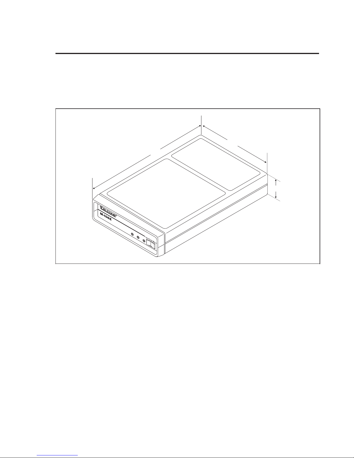
Figure 1 M-106E Remote Access Unit..............................3
Benefits........................................................4
Compatibility ..................................................4
Figure 2 Typical Installation .....................................4
Security Information ............................................5
Physical Description ............................................6
Features .......................................................7
Chapter 3: Mounting Options ..........................................11
Figure 3 Wall Mounting Strap ...................................11
Figure 4 Universal Mounting Bracket.............................12
Figure 5 Universal Mounting Shelf...............................13
Chapter 4: Installation and Basic Setup..................................14
Figure 6 M-106E Front and Back Panels...........................14
Operation WITHOUT Passwords ...............................15
Operation WITH a Single Password .............................16
Chapter 5: Programming the M-106E ...................................20
Initial Steps ...................................................20
Remote Programming, WITH User Passwords ....................21
Remote Programming, WITHOUT User Passwords ................22
General Programming Procedures ...............................24
106E-101, Issue 1 Page i
Teltone is a registered trademark of Teltone Corporation.
Copyright © 1994 Teltone Corporation.
Page 2

M-106E Reference Manual
Chapter 6: Voice Switched Amplifier ................................... 34
Chapter 7: Warranty, Return, and Technical Support ..................... 38
Programming Formats ......................................... 24
Programming Functions........................................ 25
To Exit From Programming Mode ............................... 33
Voice Switched Amplifier Functions ............................ 34
Programming the Voice Switched Amplifier ...................... 35
Warranty Information.......................................... 38
Toll Fraud Disclaimer .......................................... 38
Return Procedures for U.S. Customers ........................... 38
Return Procedures for Canadian Customers ...................... 39
Technical Support ............................................. 40
Chapter 8: Troubleshooting ........................................... 41
Chapter 9: Ordering Information ...................................... 45
Basic Units ................................................... 45
Accessories ................................................... 45
Appendix 1: Specifications ............................................ 46
Appendix 2: Glossary................................................. 49
Appendix 3: Programming Worksheets ................................. 50
Appendix 4: Programming Quick Reference............................. 54
To Enable Remote Programming (On-Site): ....................... 54
To Enter Programming Mode: .................................. 54
Appendix 5: Index ................................................... 57
Appendix 6: User Quick Reference ..................................... 59
Page ii
Page 3

Contents
COMPLIANCE INFORMATION
To comply with FCC Part 68 regulations, the following requirements must be met:
The FCC registration number of this device (AHHUSA-67638-OT-E) and ringer equivalence number (1.0B), if
requested by the telephone company, must be reported.
The sum of ringer equivalence numbers for all devices connected to a single telephone line should not exceed 5.0
for reliable operation. This device must not be installed on coin-operated telephone lines or party lines. Repair
work on this device must be done by Teltone Corporation or an authorized representative.
Part 15 Class A Notice: This equipment has been tested and found to comply with the limits for a Class A digital
device, pursuant to Part 15 of the FCC Rules. These limits are designed to provide reasonable protection against
harmful interference in a commercial environment. This equipment generates, uses, and can radiate radio
frequency energy and, if not installed and used in accordance with the instruction manual, may cause harmful
interference to radio communications. Operation of this equipment in a residential area is likely to cause harmful
interference, in which case the user will be required to correct the interference at his own expense.
The Canadian Department of Communications label identifies certified equipment. This certification means
that the equipment meets certain telecommunications network protective, operational, and safety requirements.
The Department does not guarantee the equipment will operate to the user’s satisfaction.
Before installing this equipment, users should ensure that it is permissible to connect it to the facilities of the
local telecommunications company. The equipment must also be installed using an acceptable method of
connection. In some cases, the company’s inside wiring associated with a single line individual service may be
extended by means of a certified connector assembly (telephone extension cord). The customer should be aware
that compliance with the above conditions may not prevent degradation of service in some situations.
Repairs to certified equipment should be made by the following authorized Canadian maintenance facility:
Can-am Telecommunications Associates Inc.
1845 Sandstone Manor, Unit 11
Pickering, Ontario L1W 3X9
Phone: (905) 837-7700 Fax: (905) 839-3150
Any repairs or alterations made by the user to this equipment, or equipment malfunctions, may give the
telecommunications company cause to request the user to disconnect the equipment. Users should ensure for
their own protection that the electrical ground connections of the power utility, telephone lines, and internal
metallic water pipe system, if present, are connected together. This precaution may be particularly important in
rural areas.
Caution: Users should not attempt to make such connections themselves, but should contact the appropriate
electric inspection authority, or electrician, as appropriate.
The Load Number (LN) assigned to each terminal device denotes the percentage of the total load to be
connected to a telephone loop which is used by the device, to prevent overloading. The termination on a loop
may consist of any combination of devices subject only to the requirement that the total of the Load Numbers of
all the devices does not exceed 100. The Load Number assigned to the M-106E is 8.
DOC COMPLIANCE NOTICE: This digital apparatus does not exceed the Class A limits for radio noise
emissions for digital apparatus as set out in the Radio Interference Regulations of the Canadian Department of
Communications.
DOC AVIS DE CONFORMATION: Le présent appareil numérique n’émet pas de bruits radioélectriques
dépassant les limites applicablesaux appareils numériques de la class A prescrites dans le Règlement sur le
brouillage radioélectriques édicté par le ministère des Communications du Canada.
106E-101, Issue 1 Page iii
Page 4

M-106E Reference Manual
When using your telephoneequipment, basic safety precautions should always be followed to
reduce the risk of fire, electric shock, and injury to persons, including the following:
1. Read and understand all instructions.
2. Follow all warnings and instructions markedon the product.
3. Unplug this productfrom the wall outlet before cleaning. Do not use liquid cleaners or
aerosol cleaners. Use a damp cloth for cleaning.
4. Do not use this product nearwater, for example, near a bath tub, wash bowl,kitchen sink, or
laundry tub, in a wet basement, or near a swimmingpool.
5. Do not place this product on an unstable cart, stand, or table. The product may fall, causing
serious damage to the product.
6. Slots and openingsin the cabinet and the back or bottom are provided for ventilation. To
protect it from overheating,these openings must not be blocked orcovered. The openings
should never be blocked by placing the product on a bed, sofa, rug, or other similar surface.
This product should never be placed near or over a radiator or heat register. This product
should not be placedin a built-in installation unless proper ventilation is provided.
7. This product shouldbe operatedonly from the type of power source indicated on the
marking label. If you are not sure of the type of power supply to your home, consult your dealer
or local powercompany.
IMPORTANT SAFETY INSTRUCTIONS
8. Do not allowanything to rest on thepower cord. Do not locate this product where the cord
will be abused by persons walking on it.
9. Do not overload wall outlets and extension cords as this can result in fire or electric shock.
10. Never push objects ofany kind into this product through cabinet slots as they may touch
dangerous voltage points or short out parts that couldresult in fire or electric shock.Never spill
liquid of any kind on the product.
11. To reduce the risk of electric shock, do not disassemble this product, but take it to a
qualified serviceman when some service or repair work is required. Opening or removing
covers may expose you to dangerous voltages orother risks. Incorrect reassembly can cause
electricshock when the appliance is subsequentlyused.
12. Unplug this product from the wall outlet and refer servicing to qualified service personnel
under the following conditions:
A. When the power supply cord orplug is damaged or frayed.
B. If liquid hasbeen spille d into the product.
C. If the product hasbeen exposed to rain or water.
D. If the product doesnot operate normally by following the operating instructions. Adjustonly
those controls that arecovered by the operating instructions, because improper adjustment of
other controls may result in damage an d will often require extensive work by a qualified
technician to restore the product to normaloperation.
E. If the product has been droppedor the cabinet has beendamaged.
F. If the product exhibits a distinct changein performance.
13. Avoid using a telephone (other than a cordless type)during an electrical storm. There may
be a remote risk ofelectric shock from lightning.
14. Do not use the telephone to report a gas leak in the vicinity of the leak.
SAVE THESE INSTRUCTIONS
Page iv
Page 5

Chapter 1: Getting Started
Using The Manual
This Reference Manual provides the system administrator with step-by-step
instructions for installing and programming the M-106E. The manual covers
models M-106E-01E (voice amplifier version) and -05E (unamplified).
This manual is broken into chapters and appendixes which are briefly
explained below.
Chapter 1 provides basic, introductory information required to get started
using the M-106E.
Chapter 2 is an overview of the features in the M-106E.
Chapter 3 discusses three mounting options.
Chapter 4 explains how to install and test the M-106E.
Chapter 1: Getting Started
Chapter 5 explains how to program the unit and lists the functions.
Chapter 6 reviews the Voice Switched Amplifier which is available on model
M-106-05E.
Chapter 7 reviews warranty, returning malfunctioning units, requesting
upgrades, and technical support.
Chapter 8 outlines troubleshooting procedures.
Chapter 9 lists ordering information.
Appendix 1 containsthe technical specifications.
Appendix 2 is a glossary with definitions of many terms used in this manual.
Terms defined in the glossary are
manual.
Appendix 3 provides worksheets to assist with programming the M-106E.
Appendix 4 outlines quick reference steps for programming the M-106E.
Appendix 5 is an index.
Appendix 6 is a quick reference section which should be photocopied and
given to the users after the system administrator has filled it out.
underlined the first time they appear in the
106E-101, Issue 1 Page 1
Page 6

M-106E Reference Manual
Revision Information
This manual describes the Teltone
covers models M-106-01E and -05E with part numbers 250-00171-19 and
higher.
M-106E Tips
The paragraphs below outline basic information with which you should be
familiar before working with the M-106E. Please review the following text
before continuing to the next chapter.
Entering Control Codes
®
M-106E Remote Access Unit. Issue 1
The M-106E control codes include: Reseize (default **),
Switchhook Flash (∗#),
and Disconnect (# #). You can change the control codes from the defaults to
other two- or three-digit values or you can disable them. Remember, when
entering control codes, the digits must be entered within the programmed time
period (default 1 second) or the M-106E will ignore the code.
Line Requirements
The IN line can be loop start or ground start.
DialTone
The M-106E does not provide dial tone. Instead, dial tone is sent through the
telephone lines from other equipment. In some applications, you will not
receive dial tone from these other devices. When this manual instructs you to
listen for dial tone, simply continue to the next step if dial tone is not provided
by other equipment.
Page 2
Page 7
Chapter 2: Overview
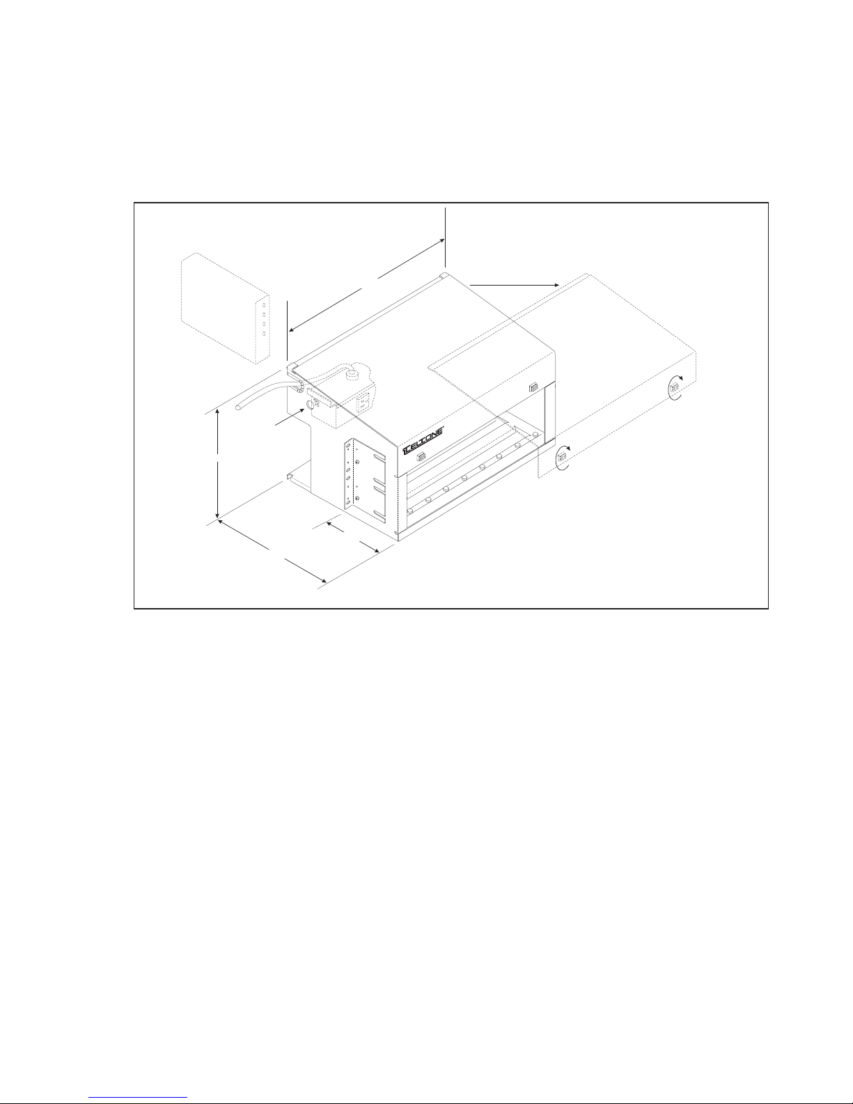
The M-106E Remote Access Unit (Figure 1) enables off-premises users to dial
in to a PBX, key telephone, or CO Centrex system in order to access WATS, FX,
and tie lines, or other specialized services or to perform system maintenance.
The unit is microprocessor controlled, and provides a number of optional
features which you can configure through software using a DTMF telephone.
Chapter 2: Overview
5.50"
9.00"
1.50"
R
Remote Access Unit
IN
O
U
T
Figure 1 M-106E Remote Access Unit
Operation
When an off-premises caller dials a telephone number dedicated to the
M-106E, the caller hears a special answer tone (in systems using a password)
or dial tone from the OUT line, if passwords are not being used. After
receiving answer tone, the caller dials a password. If the correct password is
entered, the caller hears dial tone from the OUT line indicating successful
connection to the M-106E. The caller then dials any system feature normally
available within the PBX or Centrex system. A caller can place more than one
call per incoming access using the reseize feature.
Note:
No battery backup is required because all features are stored in
permanent memory.
106E-101, Issue 1 Page 3
Page 8
M-106E Reference Manual
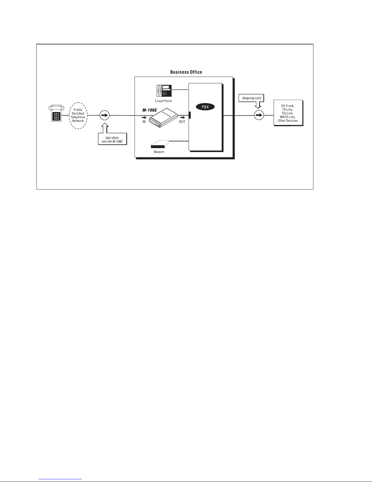
2500 Set
Interface
Figure 2 Typical Installation
Benefits
• Increased availability and usefulness of PBX and Centrex services.
Unattended access means 24-hour availability.
• Enhanced password security with hacker prevention features, such as
passwords and restrict codes.
• Control of toll calling expenses. Off-premises callers can use less expensive
WATS or dedicated lines of the office telephone system.
• Improved accounting of business calling. Long-distance charges for
business calls made off premises are included in each month’s office
telephone bills.
• Increased convenience and time savings for callers.
• Facilitated WATS line resale.
Compatibility
The M-106E may be used on any line compatible with a standard analog
DTMF telephone.
Figure 2 shows the basic M-106E installation scheme, in which the incoming
line and outgoing port are both dedicated to the M-106E. More specialized
installation schemes with undedicated incoming and/or outgoing lines are
also possible.
Page 4
Page 9

Chapter 2: Overview
Note: The sum of ringer equivalence numbers for all devices connected to the
line should not exceed 5.0.
Security Information
Passwords
Password (security code) access to the M-106E are the primary means to
prevent unauthorized use of the services for which this unit is being installed.
PasswordTips
1. Use long passwords—the longer the password, the more secure the system.
2. Change passwords—change them at least twice a year, and change the
length along with the digits.
3. Use multiple passwords—if one password has been broken, it can be
changed without impacting all users. Vary the length of passwords assigned to
different users.
4. Never disseminate the programming password (User ID number 1).
5. Monitor system usage daily and watch for excess traffic over the normal
amount of calling. The call records provided by the M-106E provide a
call-by-call and user-by-user (User ID number) listing.
6. Avoid using numbers that can be guessed by association, such as personal
or company telephone numbers, addresses, names, or vanity license plates
(names associated with numerals on pushbutton phone keypads; for example,
“NAMES” = 62637).
Restrict Codes
The restrict code feature provides a means to allow different levels of user
privileges based on the restrict codes assigned to different passwords.
The restrict code feature provides limited protection against abuse of calling
privileges. While some devices are better than others, virtually all devices of
this nature can ultimately be fooled into allowing certain calls which you want
to restrict.
The M-106E cannot restrict calls when dial tone is heard on its outgoing side,
as may be the case when the called party hangs up. The M-106E checks the
first digits dialed by the user on initial access, after a retrial (**), and after a
switchhook flash (*#). When it determines that the dialed digits cannot match
the assigned restrict codes, the call is allowed. If the caller dials a string of
digits that matches an assigned restrict code, the M-106E will disconnect both
incoming and outgoing lines.
106E-101, Issue 1 Page 5
Page 10

M-106E Reference Manual
Restrict Code Tips
1. Do not use restrict codes without first requiring a password for access.
Password protection is far more effective in preventing abuse than restrict
codes.
2. Test your system to determine whether dial tone is returned when a called
party hangs up, as follows. Connect a telephone to the line intended for use as
a the M-106E outgoing line. Test for dial tone under several conditions. Dial a
local extension, voice mail, and a local Central Office exchange number ( a
telephone number with the same prefix as yours) and wait for the called party
to hang up. Dial several incomplete and nonexistent numbers and wait for the
recorded announcements or intercept operators. If dial tone is returned in any
of these cases, the M-106E will not be able to restrict calls. Unauthorized
numbers (1+, 0+, 9+ and so on) may be restricted by the Central Office or the
PBX, however.
3. Use outgoing line toll restrictions supplied by the Central Office or the PBX
whenever possible, whether or not the M-106E restrict codes can also be used.
Physical Description
Dimensions
The unit is packaged in a modem-sized housing (1.5 x 5.5 x 9.0 inches). See
Figure 1.
LED
Three LEDs on the front panel indicate the following:
• incoming line (IN) seized (red)
• outgoing line (OUT) seized (red)
• unit enabled/disabled (green):
—slow flash indicates the unit is ready
—rapid flash indicates the unit is in program mode
—LED off indicates unit is disabled
The front panel also has a rocker switch used to enable or disable the M-106E,
or to place it in programming (PROG) mode.
Power and Line Connections
The back panel has two RJ-11C jacks for connecting incoming and outgoing
lines, and an AC power jack
Page 6
Page 11

Chapter 2: Overview
Line Requirements
The incoming line may be loop start or ground start. Ground start lines
provide immediate forced disconnect when the user hangs up. However, with
loop start on the incoming line, if the user fails to enter the disconnect control
code (default # #) before hanging up, the M-106E will be held in a busy state
unless either (1) the central office is capable of forcing disconnect or (2) one of
the M-106E forced disconnect timeout options (Functions 4, 8, 9, or 18) has
been enabled. The outgoing line must be loop start.
Polarity
Both incoming and outgoing M-106E ports are polarity guarded. That is, a
reversal of Tip and Ring will not affect unit operation.
Input Power
The unit operates from standard 120 VAC wall power. A Class 2 UL and CSA
approved AC-to-AC transformer is included which converts the input voltage
!
to voltages required by the unit.
Features
The M-106E provides many features that can be enabled or adjusted by the
customer. The unit is programmed by placing a call to it and entering
programming mode. (There is no provision for connecting a telephone directly
to the unit in order to program it.) Programmable options are summarized
below. Programming procedures are described in Chapter 5.
Passwords
User access can be restricted by requiring entry of a password. A maximum of
25 passwords can be programmed, each 3 to 10 digits long. Any combination
of DTMF digits 0 through 9 can be used. The password requirement can be
disabled. Passwords must be followed by #.
When you receive the M-106E from the factory, Function 1, Password
Assignment, will be enabled, but passwords will not have been assigned.
Programmable Control Codes
These two or three digit codes control the M-106E. They can be changed from
their factory defaults to other values with either two or three characters in
length. Control codes include: Reseize (default **), Programming Access (default
#*), Switchhook flash (default *#), and Disconnect (default # #). Disconnect,
Reseize and Switchhook flash can be disabled by setting them to zero.
106E-101, Issue 1 Page 7
Page 12

M-106E Reference Manual
Restrict Codes
Callers can be prevented from accessing telephone numbers beginning with
certain digits. The M-106E can recognize up to 10 restrict codes, each with a
maximum of 5 digits. Any of these codes can be assigned individually to each
user.
AnswerTone
The unit is factory programmed to return a two-second answer tone, that
sounds similar to dial tone, to the caller to indicate that it is ready to accept a
password. The tone can be disabled or set to one of three volume levels.
Call Duration Timing
A timer can be set (from 1 to 99 minutes) to prevent callers from monopolizing
the unit or to reset the unit if a caller has failed to enter the disconnect control
code. Callers will hear a warning tone 16 seconds before the timer disconnects
the unit. The timer can be set differently for each password, or disabled by
setting the timer value to 0.
Switchhook Flash
This feature, if enabled, enables a caller to generate a switchhook flash by
entering the Switchhook Flash control code (default *#).
Reseize
This feature, if enabled, allows the user to temporarily disconnect from the
outgoing line by entering the reseize control code (default **) in order to place
another call without reaccessing the M-106E. In addition, the duration of the
disconnect for the reseize is also programmable.
Manual Disconnect
The disconnect option enables a caller to disconnect from the unit by entering
the disconnect control code (default # #). This feature is necessary on loop start
lines without forced disconnect to ensure that the unit disconnects from the
incoming and outgoing lines.
Idle Detect
The M-106E can be programmed to monitor activity on the line during an
established call. Whenever the line is idle for a programmable period of time (1
to 99 minutes), the unit will perform a switchhook flash on the incoming line,
then check for the presence of a tone between 305 and 640 Hz (i.e., dial tone).
When a tone is detected, the unit will disconnect both lines.
Page 8
Page 13

Chapter 2: Overview
Dial ToneDetect
If the caller hangs up without entering the disconnect code, this feature causes
the M-106E to disconnect both lines if dial tone is present for a programmable
length of time.
Busy/Reorder Disconnect
The unit can be programmed to disconnect after receiving busy or reorder tone
for a specified time.
Detect Standard Ring Only
The unit can be programmed to detect only the standard ring of 2 seconds on,
4 seconds off, and to ignore any calls that do not match this pattern.
Rings Before Answer
The unit can be programmed to answer after 1 to 16 rings.
Prevent
The unit can be programmed to block all user access after repeated attempts to
enter an invalid password. The number of invalid attempts, the unit’s response
to the caller, and the amount of time the feature is active, are also
programmable.
Milliwatt Detect
If this feature is enabled, the M-106E will monitor the line during an
established call for 1004 Hz test tone. When this tone is detected for a
programmable time (1 to 300 seconds), the unit will disconnect the outgoing
line for 2 seconds, then reseize it for a new call (as with retrial).
Non-volatile Memory
Since all programmable function configuration information is saved in
EEROM and is not affected by loss of power, batteries are not required.
Voice Verification of Program Options
The M-106E has a limited synthesized voice vocabulary (digits 0 through 9 and
the word “any”) to respond to user queries about the current settings of
program options. The voice level is adjustable.
106E-101, Issue 1 Page 9
Page 14

M-106E Reference Manual
Remote Programming
This feature allows system administrator to call the unit from any location and
enter programming commands (thus, physical access to the unit to set the
programming mode switch is not required).
Voice Switched Amplifier
Where low volumes exist, an internally mounted amplifier in M-106-01E units
improves audibility to both parties.
Page 10
Page 15
Chapter 3: Mounting Options
The three mounting options described in this chapter are available for
mounting any of the M-106E Remote Access Unit(s). If you wish to order one
of these mounting packages, please refer to Chapter 9: Ordering Information
which provides model numbers and brief descriptions.
The following information provides a quick overview of mounting the unit. If
you require more detail, please refer to the instructions accompanying the
mounting hardware.
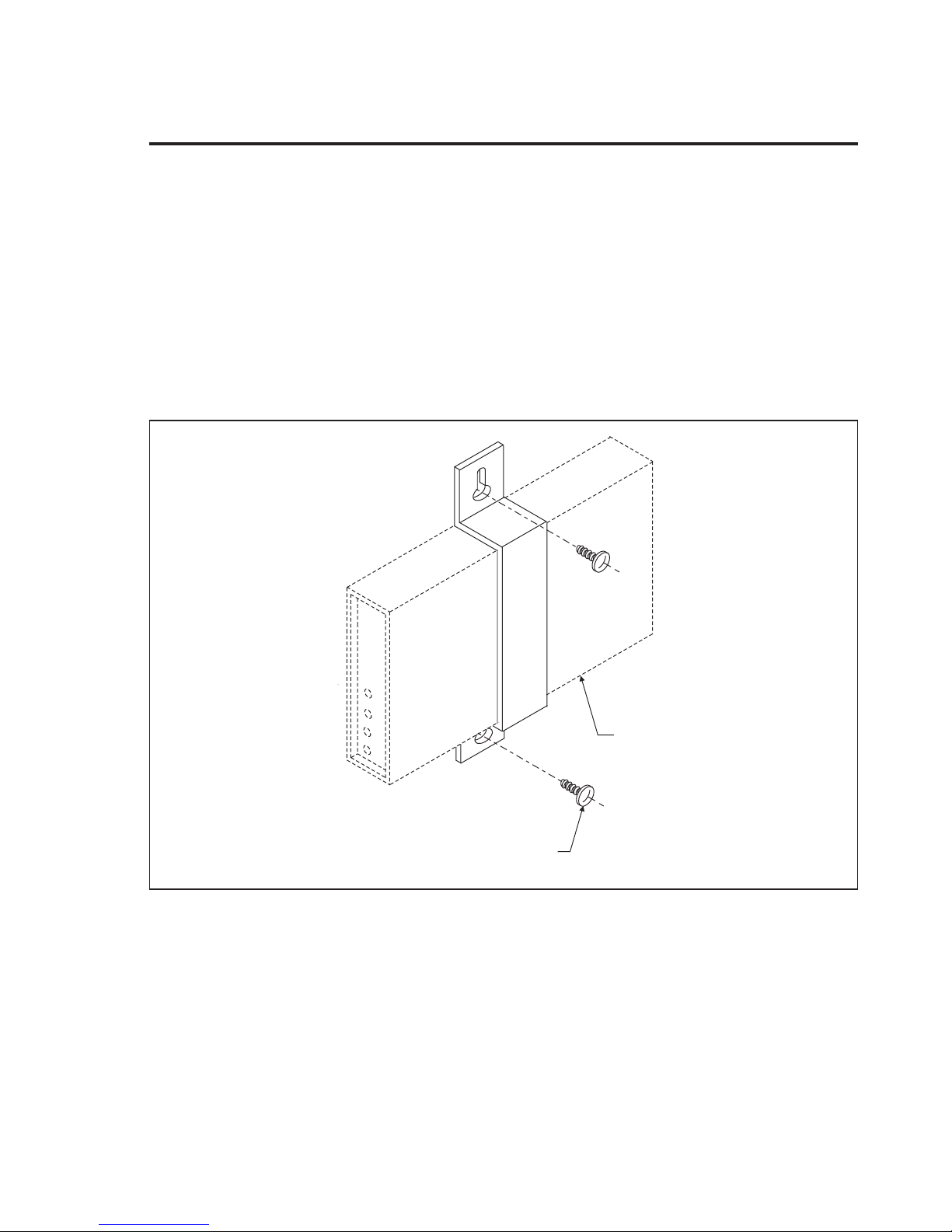
A single M-106E unit can be mounted to a wall using the Mounting Strap
(UM-110-101) shown below. This simple installation kit comes with a sheet
metal bracket and two screws.
Chapter 3: Mounting Options
M-106E
#10-13 X 3/4 LONG
WOOD SCREW
2 PLACES
Figure 3 Wall Mounting Strap
106E-101, Issue 1 Page 11
Page 16
M-106E Reference Manual
For multiple unit installations, the Universal Mounting Bracket (UM-111-401)
may be ordered separately. The bracket, as shown below, enables up to four
M-106E units to be wall mounted.
1.625"
(41mm)
6.50"
(167mm)
9.60"
(244mm)
UM
-111
-401
Orient mounting
feet toward wall.
Figure 4 Universal Mounting Bracket
R
D
.C
1
1
-1
M
U
Page 12
Page 17
Chapter 3: Mounting Options
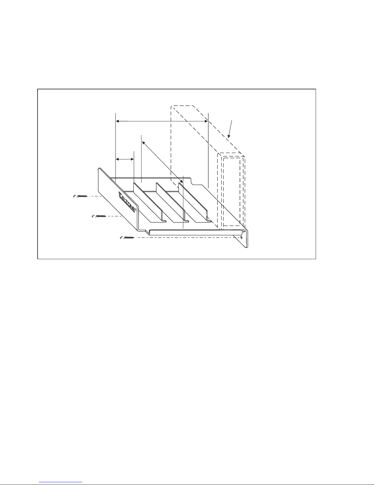
The Universal Mounting Shelf (UM-113-801) which mounts up to eight
M-106E units. This shelf is a sheet metal housing designed for insertion in a
standard 19" or 23" equipment rack. An eight outlet power strip is built into
the unit; two of the outlets are accessed by removing the front cover, as shown
in the diagram below.
Install unit from
rear of rack.
17.25"
13-801
-1
UM
CIRCUIT
BREAKER
10.25"
12.00"
5.00"
Mounting flanges can be flipped to accommodate 23"
racks (short side of flange to unit). For flush mounting to
front of equipment rack, rotate flange and use mounting
holes toward front of each side of rack unit.
Figure 5 Universal Mounting Shelf
Remove cover to access the two
power outlets on inside of power
strip. Rotate fasteners one
quarter turn to remove cover.
R
D
13.C
-1
M
U
106E-101, Issue 1 Page 13
Page 18
M-106E Reference Manual
Chapter 4: Installation and Basic Setup
CAUTION:
(1) Never install telephone wiring during a lightning storm.
(2) Never install telephone jacks in wet locations unless the jack is specifically
designed for wet locations.
(3) Never touch uninsulated telephone wires or terminals unless the telephone
line has been disconnected at the network interface.
(4) Use caution when installing or modifying telephone lines.
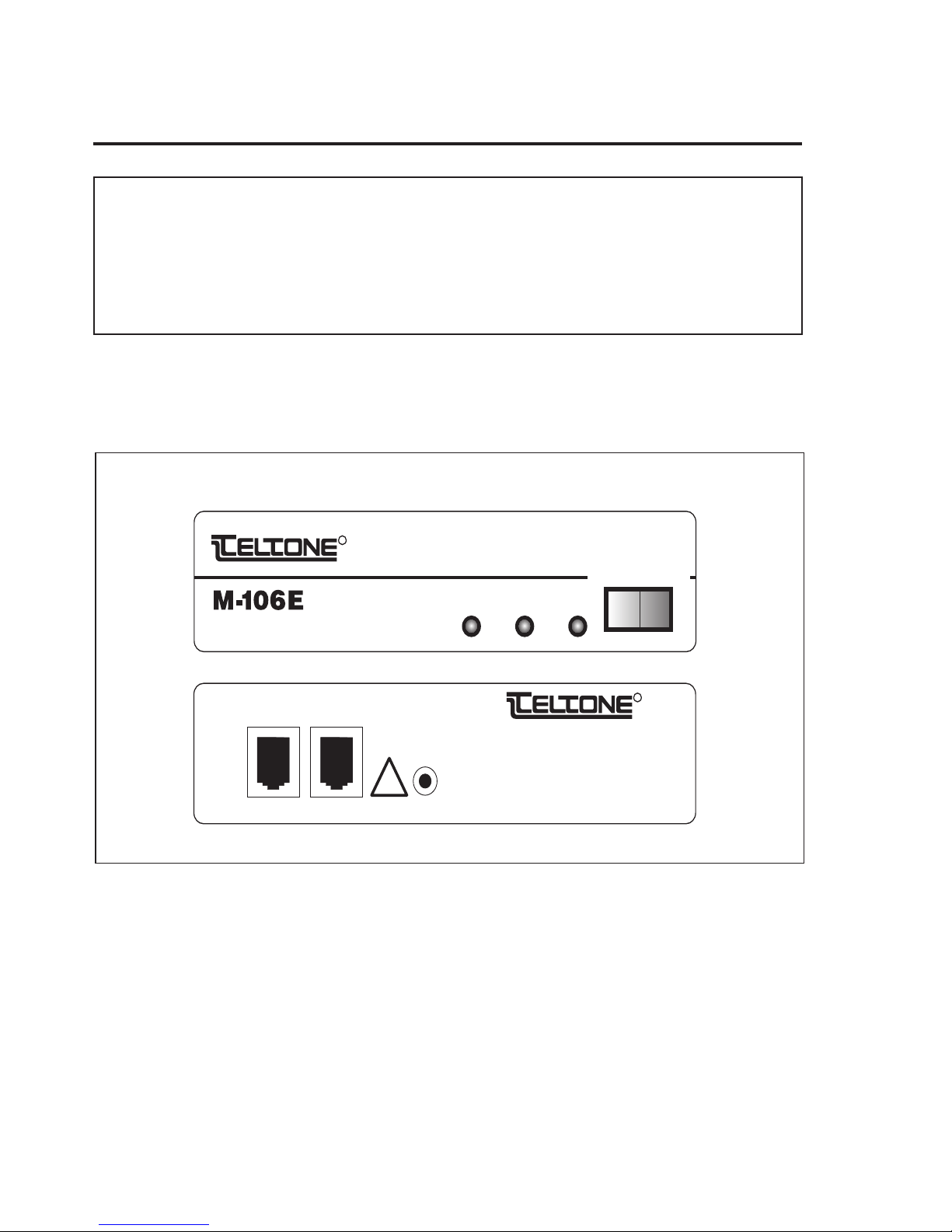
This section describes the steps necessary to install the M-106E for basic
operation with or without password access. Before continuing, please see
Figure 6 which shows the front and back panels.
R
Program/Ready/Disable
IN OUT
Remote Access Unit
M-106E Front Panel
INPUT
IN
OUT
POWER
PACK
12 VAC 60 HZ
1/2 AMP
R
!
M-106-01E, -05E Back Panel
Figure 6 M-106E Front and Back Panels
Unpack the M-106E and verify that the following items were received:
• M-106E unit, Class 2 AC power pack
, and Product Registration card
• Return any items that appear damaged to Teltone. (See Chapter 7 for
instructions on returning units.)
• You will also require two RJ-11C cords (not supplied).
Page 14
Page 19

Chapter 4: Installation and Basic Setup
Operation WITHOUT Passwords
This means that remote programming is disabled. Perform the following steps
to install and test the unit for operation without password access:
Step 1: Press switch to READY
• Press the front panel switch to READY.
Step 2: Connect power cord
• Connect the transformer and power cord between the unit and a 120 VAC
outlet. The green light should begin flashing.
Step 3: Connect incoming line
• Connect the incoming telephone line to the IN jack on the back of the
M-106E. Determine the telephone number and write it in the blank space:
.
Step 4: Connect outgoing line
• Connect the outgoing telephone line to the OUT jack on the back of the
M-106E.
Step 5: Enter Programming Mode
• Press the front panel switch to PROGRAM until the green light flashes
quickly.
Note: While the unit is in programming mode, a call is disconnected
whenever 2 minutes have elapsed without entry of a digit.
Step 6: Disable password access
• From a local phone, dial the M-106E incoming line number. When the unit
answers with three short beeps, enter the following to disable password
access:
∗15∗0#
• The unit will respond with three short beeps if the command was accepted.
If you hear error tone, re-enter the entire command.
Step 7: Disconnect
• Enter the disconnect control code (default ##), then hang up. (The second #
must be entered within 1 second of the first.)
106E-101, Issue 1 Page 15
Page 20

M-106E Reference Manual
Step 8: Reaccess unit
• Reaccess the unit. After the unit ring trips, the red IN and OUT indicators
Step 9: Make test call
• Place a call through the M-106E and verify that the voice levels are
• M-106-01E units: Press the front panel switch to PROGRAM until the
should light and you should hear dial tone from the outgoing line.
satisfactory. If not, follow the instructions for the model you are using:
green light flashes. Then place a call to the unit and adjust the amplifier
gain as instructed in Chapter 6, Function 12.
-or-
M-106-05E units: An amplifier should be added to the unit. This requires a
factory upgrade; see Chapter 7 for information on returning units.
• The unit is now ready for use. If the above procedures cannot be
completed successfully, press the front panel switch to PROGRAM until
the green light flashes quickly. Repeat Steps 1-9 before going to the
troubleshooting procedures.
• Refer to Chapter 5 for information on how to set other M-106E functions if
required.
Operation WITH a Single Password
Remote Programming Disabled for this operation. Perform the following steps
for operation with password access:
Step 1: Press switch to READY
• Press the front panel switch to READY.
Step 2: Connect power cord
• Connect the transformer and power cord between the unit and a 120 VAC
outlet. The green light should begin flashing.
Step 3: Connect incoming line
• Connect the incoming telephone line to the IN jack on the back of the
M-106E. Determine the telephone number and write it in the blank space:
Page 16
.
Page 21

Chapter 4: Installation and Basic Setup
Step 4: Connect outgoing line
• Connect the outgoing telephone line to the OUT jack on the back of the
M-106E.
Step 5: Determine if user timeout required
• Determine whether the timeout option is to be used to limit the length of
each user session. Write in that time (1-99 minutes or 0 if no timeout is
required) in Step 10.
Step 6: Determine password
• Determine the password (3 to 10 digits) and fill in the blank space in Step 8.
Step 7: Enable password access
• Press the front panel switch to PROGRAM until the green light flashes
quickly. From a convenient location, dial the M-106E telephone number.
When the unit answers (you will hear three beeps), enter the following
command to enable password access:
∗15∗1#
• Listen for three beeps to confirm that password access is enabled.
Step 8: Assign User 2 password
• Enter the following command (the blank is the user password as
determined in Step 7):
∗1∗2∗ #
• You have just assigned a password to User number 2. You will hear three
beeps if the command was entered correctly. If you hear error tone, redial
the command making sure you include the
Notes:
Step 9: Verify password
• Verify the password by dialing the following:
(a) the unit will not respond until it receives the #
(b) If you misdial and have not yet entered a #
000# and listen for error tone.
(c) Passwords may not end with 000.
∗ and # digits as shown.
, cancel the entry by dialing
∗77∗1∗2#
• The unit will provide a voice response in the following format: “two” beep
<password> beep beep beep
106E-101, Issue 1 Page 17
Page 22

M-106E Reference Manual
• If the password does not match what you wanted, repeat Steps 9 and 10.
Step 10 (optional):Set timeout
• If a user timeout is not required, proceed to Step 12 to ensure that this
• Set the timeout to the predetermined value by dialing the following (the
• The unit will respond with three beep tones indicating that the timeout is
• Repeat this step if you hear error tone. (This command assigns the same
feature is turned off.
-or-
blank is the user timeout as determined in Step 5):
∗4∗2* #
set, or an error tone.
timeout to all users. If you wish to assign different timeouts for individual
users, please see the explanation of Function 4 in Chapter 5 and enter the
command as instructed.)
Step 11: Verify timeout
• Verify the time, or no timeout, by dialing the following:
∗77∗4∗2#
• The unit will respond with the time allowed (or 0 for no timeout) and three
beeps. If it does not, repeat Steps 10 and 11.
Step 12: Disconnect
• Enter # # and hang up. (The second # must be entered within 2 seconds of
the first.)
Step 13: Reaccess unit.
• Reaccess the unit. After the unit ring trips the red IN indicator should light
and you should hear a 2 second tone. Enter the password assigned in Step
9, followed by #
. You will hear dial tone.
Step 14: Make test call
• Place a call through the M-106E and verify that the voice levels are
satisfactory. If not, either:
• M-106-01E units: Press the front panel switch to PROG. Call the unit and
adjust the amplifier gain as instructed in Chapter 6, Function 12.
• M-106-05E units: An amplifier should be added to the unit. This requires a
factory upgrade; see Chapter 7 for information on returning units.
Page 18
Page 23

Chapter 4: Installation and Basic Setup
The unit is now ready for use with one password, user timeout as required,
and all other functions set to Default.
• If the above procedures cannot be completed successfully, press the front
panel switch first to PROGRAM until the green light flashes quickly, and
repeat the procedure once again before going to the troubleshooting
procedures. Refer to Chapter 5 for information on how to set other M-106E
functions if required.
106E-101, Issue 1 Page 19
Page 24

M-106E Reference Manual
Chapter 5: Programming the M-106E
This chapter provides information needed to adjust the M-106E options.
You will normally program the M-106E by dialing the unit from a pushbutton
telephone and entering a password. Before you can do this, however, you will
have to perform the initial steps described below.
Whether or not you will require passwords to use the M-106E, you must
assign at least one password before the unit can be accessed for remote
programming. The M-106E recognizes “User 1” as the programming or system
administration password.
Notes:
The M-106E installer may already have assigned a password to “User 2”. You
can determine what, if any, programming has been done on your unit by using
Function 77.
(1) When you access programming mode, the green light on the front
panel will flash.
(2) Calls will be disconnected whenever two minutes elapse without entry
of a digit.
Initial Steps
Step 1: Determine options to be set
• The telephone number of the M-106E___________________________
• Will you require users to enter a password? Yes
• Do you want any of your users to be disconnected from the M-106E after
exceeding a time limit? Yes
Step 2: (optional) Fill out planning worksheets
• If you answered “Yes” to any of the above, you may find it helpful to use
the planning worksheets in Appendix 3 to list the passwords and timeout
values to be assigned to each user number.
No
No
• Do any other options need to be set to something other than the Default?
Use the worksheet in Appendix 3, if you wish, to list the changes.
• To set up the unit for remote programming, see Remote Programming.
Page 20
Page 25

Chapter 5: Programming the M-106E
Remote Programming, WITH User Passwords
For setup procedures for operation with user passwords, follow the steps
below.
Step 1: Enter programming mode
te:
No
• Press the front panel switch to PROGRAM until the green light flashes, or
Step 2: Access the unit
• Dial the M-106E telephone number and listen for three beeps.
Step 3: Enable password access
• Enter the command:
While the unit is in programming mode, calls are disconnected
whenever 2 minutes have elapsed without entry of a digit.
request this service if you do not have access to the unit.
*15*1#
• Listen for three beeps to confirm that the command was entered correctly.
Note:
Whenever you make an error before the # is entered, enter 000# to
cancel the command, then begin again.
Step 4: Enable remote programming
• Enter the command:
*98*1#
• You will hear three beeps if the command was entered correctly.
Step 5: Assign system administrator password
• Enter the following command (note that the password for User 1 must be
entered twice, as shown):
*1*1*NN...N#*1*1*NN...N#
where: NN...N is the password (3 to 10 digits).
• Listen for three beeps to confirm that the password is accepted.
Step 6: Verify password
• Verify the password, if you wish, as follows:
*77*1*1#
106E-101, Issue 1 Page 21
Page 26

M-106E Reference Manual
• You will hear a voice and tone response in the following format: “one”
Step 7: Exit programming mode
• Enter the disconnect control code (default # #), then hang up.
beep “NN...N” beep beep beep
Note:
If you do not enter # # before you hang up, the unit will automatically
disconnect after a time delay. Routinely entering # # before hanging up
avoids the delay for a forced disconnect before you can reaccess the unit.
Step 8: Access unit for programming
• When you are ready to begin programming, dial the M-106E telephone
number.Listen for a two-second answer tone indicating the unit is ready to
receive a password. Enter the User 1 password, followed by #.
Remote Programming, WITHOUT User Passwords
For setup procedures for operation without user passwords, follow the steps
below.
Note:
Step 1: Enter programming mode
Note:
A system administrator password (“User 1”) must be assigned to
enable access to the unit for remote programming, even though user
passwords are not used.
While the unit is in programming mode, calls are disconnected
whenever 2 minutes have elapsed without entry of a digit.
Page 22
• Press the front panel switch to PROGRAM until the green light flashes
quickly, or request this service if you do not have access to the unit.
Step 2: Access the unit
• Dial the M-106E telephone number and listen for three beeps.
Step 3: Disable password access
• Enter the command:
*15*0#
• Listen for three beeps to confirm that the command was entered correctly.
Note:
Whenever you make an error before the # is entered, enter 000# to
cancel the command, then begin again.
Page 27

Chapter 5: Programming the M-106E
Step 4: Enable remote programming
• Enter the command:
∗98∗1#
• You will hear three beeps if the command was entered correctly.
Step 5: Assign system administrator password
• Enter the following command (note that the security code for User 1 must
be entered twice, as shown):
∗1∗1∗NN...N#∗1∗1∗NN...N#
where: NN...N is the password (3 to 10 digits).
• Listen for three beeps to confirm that the password is accepted.
Step 6: Verify password
• Enter the command:
∗77∗1∗1#
• Listen for a voice and tone response in the following format: “one” beep
“NN...N” beep beep beep
Step 7: Disconnect
• Enter the disconnect control code (default # #), then hang up. (The second #
must be entered within 2 seconds of the first.)
Note:
Step 8: Access unit for programming
• When you are ready to begin programming, dial the M-106E telephone
Step 9: Enter password
• Enter the program access control code (default #
If you do not enter the disconnect control code (default # #) before you
hang up, the unit will automatically disconnect after a time delay.
However, routinely entering # # before hanging up avoids a wait time for a
forced disconnect before you can access the unit again.
number. You will hear dial tone from the outgoing line.
∗). (Enter the ∗ within the
programmed interdigit time. This applies to all 2-character commands: # #,
∗∗, ∗#, and #∗ when you are not in programming mode.)
• Wait for the dial tone to stop. You will hear a two-second tone indicating
the unit is ready to receive a password.
106E-101, Issue 1 Page 23
Page 28

M-106E Reference Manual
• Enter the User 1 password, followed by #.
• You will hear three beeps if the password was entered correctly. You can
General Programming Procedures
now proceed with programming.
Note:
Whether or not you require passwords to access your M-106E unit, a password
must be entered to enable you to program the unit. Use one of the following
procedures:
Passwords Enabled:
• Dial the M-106E telephone number. You will hear a 2-second tone (unless
• When the tone ends, enter the system administration (User 1) password,
• Begin programming.
Without Passwords:
• Dial the M-106E telephone number. You will hear dial tone from the
• Enter the programming access control code (default # *). You will hear a
While the unit is in programming mode, calls are disconnected
whenever 2 minutes have elapsed without entry of a digit.
this tone was disabled; see Function 2).
followed by #. You will hear three beeps.
outgoing line.
2-second tone (unless this tone was disabled; see Function 2).
Page 24
• When the tone ends, enter the system administration (User 1) password,
followed by #. You will hear three beeps.
• Begin programming.
Programming Formats
All programming functions begin with * and end with #. The general
command formats are as follows:
∗<function>∗<configuration for that function>#
When functions are assigned to individual users:
∗<function>∗<user ID>∗<configuration>#
If the command is valid, the unit will return a confirmation tone of three short
beeps. If not, error tone is given.
Page 29

Chapter 5: Programming the M-106E
Note:
A summary of the following information is provided in Appendix 4 for
quick reference.
Programming Functions
Select the functions necessary for your application using any or all of those
described in this chapter. If a function must be used in conjunction with
another, both functions must be programmed.
Function 1: Password Assignment
A password may be any digit string from 3 to 10 digits long. Up to 25
passwords can be assigned. “User 1” is a privileged password for system
administration. (Default = enabled, but no passwords assigned.)
In addition to assigning passwords, password access must be enabled. Even if
passwords were assigned, the M-106E will process calls without password
entries if password access (Function 15) is disabled. To enable password
access, enter the following:
*15*1#
To assign a User 1 or system administrator password, enter the following:
*1*1*NN...N#*1*1*N...N#
where: NN...N is the password (3 to 10 digits) in both places. (The
password for User 1 must be entered twice, as shown.)
To assign passwords for Users 2 through 25, enter the following:
*1*UU*NN...N#
where: UU is the user number (1 or 2 digits)
NN...N is the password (3 to 10 digits)
To delete the User 1 password, enter:
*1*1*#*1*1*#
To delete any other password, enter:
*1*UU*#
where: UU is the user number.
Function 2: Answer Tone Enable/Disable
When enabled, this function returns a 2 second answer tone to prompt the
caller to enter a password. This function can be disabled, if desired, to frustrate
attempts to break the M-106E access codes.
To enable answer tone (Default), enter:
*2*1#
106E-101, Issue 1 Page 25
Page 30

M-106E Reference Manual
To disable answer tone, enter:
Function 3: Set Answer Tone and Voice Level
This function sets levels of both answer tone and voice. The levels can be
adjusted upward or downward from the default:
Function 4: Set User Timeout
This function enables you to program the M-106E to disconnect the user after
the specified time limit. Times can be set separately for each user, or a single
timeout for all users can be set with one command.
*2*0#
*3*L#
where: L = 1 to 3:
1 sets the level to -16 dBm
2 sets the level to -10 dBm (Default)
3 sets the level to -4 dBm
Note:
If passwords are disabled, the unit will use the timeout value stored
for user number 25.
To set timeouts for specific users, enter:
*4*UU*TT#
where: UU = the user number (1 or 2 digits)
TT= the timeout in minutes (1 to 99 minutes) (Default = 99)
To assign timeout (TT) to all users, enter:
*4*0*TT#
To assign “no timeout” to a user, enter:
*4*UU*# (or *4*UU*0#)
Note:
The time specified is the total time for each M-106E access. That is, the
timer does not reset with each retrial.
Function 6: Reseize Duration
This function sets the amount of time the M-106E remains on-hook when
Function 34, Reseize Code is sent or if set to 0, disables the reseize function.
*6*TT#
where: TT=0, 5-30 (Default = 20 seconds)
The reseize duration is measured in tenths of a second. When TT=20, the
reseize duration is two seconds. This function works in conjunction with
Function 34, which assigns the Reseize Code.
Page 26
Page 31

Chapter 5: Programming the M-106E
For example: *6*18# = 1.8 seconds
This value may need to be adjusted depending on the requirements of your
telephone system.
Function 8: Idle Detect Time (Silent Interval)
The M-106E will monitor the line for the specified period of silence, do a
switchhook flash, then look for dial tone and, when dial tone is detected for 5
seconds, will disconnect. The default setting for this function is disabled.
To set the length of time that silence must be present on the line before the unit
will look for dial tone, enter:
*8*TT#
where: TT may be 0-99 minutes.
In some installations (including those in which the incoming line is a loop start
line and the central office is not able to force disconnect), the M-106E may be
unable to disconnect without special procedures such as this one.
To disable this feature (default), enter:
*8*0#
Function 9: Dial Tone Detect Time (Initiate Disconnect)
This function forces the M-106E to disconnect after dial tone has been present
for the specified time. (Default is disabled.) In some installations (including
those in which the incoming line is a loop start line and the central office is not
able to force disconnect), the M-106E may be unable to disconnect without
special procedures such as this one.
To specify the time dial tone must be present, enter:
*9*TT#
where: TT = 5 through 20 (seconds).
To disable disconnect on dial tone detection (Default), enter:
*9*0#
Function 15: Password Access Enable/Disable
Requires the caller to enter a password in order to access the M-106E. To
operate the M-106E without password access, disable this function.
To enable the password access requirement (default), enter:
*15*1#
To disable the password access requirement, enter:
*15*0#
106E-101, Issue 1 Page 27
Page 32

M-106E Reference Manual
Note:
If passwords are disabled, the unit will use the values stored for user
number 25 for any functions that would otherwise be assigned to
individual users, except remote programming which requires a password
for User 1.
Function 16: Detect Standard Ringing Only
This function programs the M-106E to answer only certain calls.
When this function is enabled, the M-106E will only detect ringing with a
cadence of 2 seconds on, 4 seconds off. All other calls will be ignored. When
this function is disabled, the M-106E will answer all calls after 400 ms of
ringing.
To enable the function; M-106E ignores distinctive ringing (will not answer),
enter:
*16*1#
To disable the function; M-106E answers all calls (default), enter:
*16*0#
Note:
This feature is automatically disabled whenever the front panel switch
is set to PROGRAM to ensure that you can access the unit.
Function 17: Set Number of Rings
This function determines the number of rings required before the M-106E
answers a call to it. If the front panel switch is set to PROGRAM, the M-106E
answers on one ring.
*17*RR#
where: RR is the number of rings (1 - 16). (Default= 1)
Function 18: Busy/Reorder Tone Detect
Programs the unit to disconnect after receiving busy or reorder tone for the
specified time.
*18*TT#
To specify the number of seconds busy or reorder tone must be present to
cause the unit to disconnect, enter:
where: TT = 0, disables the feature (default)
TT = 5 - 20 seconds, enables the feature and sets the amount of
detection time before disconnect.
To enable the feature and disconnect after 12 seconds of busy or reorder tone,
enter:
*18*12#
Page 28
Page 33

Function 20: Restrict Code Definition
Chapter 5: Programming the M-106E
Note:
This feature cannot be used if dial tone is returned on the M-106E
outgoing line when a called party hangs up. If you intend to use this
feature, perform the following tests to determine whether it is suitable for
your application.
• Connect a telephone to the line being used as the M-106E outgoing line.
• Dial a local extension, voice mail, and local Central Office exchange
number (a telephone number with the same three-digit prefix as yours)
and wait for the called party to hang up.
• Dial several incomplete and nonexistent numbers and wait for recorded
announcements or intercept operators. If dial tone is returned in any of
these cases, the M-106E will not be able to restrict calls. The Central Office
or the PBX may be able to restrict unauthorized numbers (1+, 0+, 9+, and
so on) as necessary, however.
The M-106E can store up to 10 five-digit codes representing call categories that
can be disallowed for specified users. Each code may then be assigned to any
users (see Function 21).
The M-106E checks the first digits dialed by the caller on initial access, after a
retrial (**), and after a switchhook flash (*#). When it determines that the
dialed digits cannot match the assigned restrict codes, the call is allowed. If the
caller dials a string of digits that matches an assigned restrict code, the call is
disconnected.
*20*C*DDDD#
Enter this command to program a digit sequence restrict code C. Restrict codes
0-9 and digit sequences of up to 5 digits may be used. You can enter * as a wild
card indicating any digit.
For example, entering *20*3*12345# prevents call attempts beginning with
digits 12345 by any user to whom Restrict Code 3 is assigned (see Function 21,
below).
Default = No restrict codes defined.
This command deletes the digits associated with Code C.
*20*C*#
Note:
If passwords are disabled, the unit will restrict the codes assigned for
User 25.
Function 21: Restrict Code Assignment
Use this function to assign restrict codes to users. The codes are defined using
Function 20, above. The default setting is no codes.
106E-101, Issue 1 Page 29
Page 34

M-106E Reference Manual
To assign the specified code or codes to user UU:
For example: *21*3*1# assigns the code 1 to User 3. If you defined Code 1 = 604
or 1604 if required in your area), User 3 will be unable to place any calls to area
code 604. If you defined Code 1 = 9, User 3 will be unable to make any calls
beginning with the digit 9 (thus restricting User 3 from placing outside calls
through a PBX that required callers to dial 9 for outside calls.)
To assign codes 1, 2, and 3 to User 3, enter: *21*3*123#
To remove all restrict codes from User UU, enter: *21*UU*#
To assign the specified code(s) to all users, enter: *21*0*C# or *21*0*C...C#
Function 25: Prevent
This function blocks all user access to the unit after repeated attempts to enter
an invalid password, as specified in Functions 26, 27, and 28.
*21*UU*C# or *21*UU*C...C#
If the default values are used, whenever the unit receives five consecutive
invalid passwords, the unit will block further access by any caller for five
minutes. Within that five-minute period, callers will receive error tone. These
values can be adjusted as described in Functions 26, 27, and 28.
To enable Prevent, enter:
*25*1#
To disable the feature (default), enter:
*25*0#
Function 26: Type of Prevent
This function determines the type of response given to the caller when Prevent
(Function 25) is activated.
*26*R#
where: R = 0, callers receive error tone while prevent feature is activated
(Default)
R = 1, unit ignores ringing while prevent feature is activated
R = 2, unit answers but ignores all passwords while prevent
feature is activated
Function 27: Number of Invalid Attempts Before Prevent
This function sets the number of consecutive invalid password entries before
Prevent (25) is activated. The number of invalid entries can be made over any
time period.
*27*NN#
Page 30
Page 35

Chapter 5: Programming the M-106E
where: NN = 1 through 20 attempts to enter an invalid password.
(Default = 5)
Function 28: Prevent Duration
This function sets the number of minutes Prevent (Function 25) remains active
by specifying the number of minutes (1 through 20) that Prevent (Function 25)
will be in effect before allowing any caller to enter a valid password.
*28*MM#
where: MM=number of minutes 1-20, (Default = 5)
Function 34: Reseize Code
This feature works in conjunction with Function 6.
*34*N*DDD#
where: N is the number of digits in the control code
DDD can be 0, 2 or 3 digits in length, valid entries are 0-9, * or #
(Default=**)
If N=0, the feature is disabled
Function 35: Switchhook Flash Code
This feature is used to send a switchhook flash.
*35*N*DDD#
where: N is the number of digits in the control code, 0=disabled
DDD can be 0, 2- 3 digits in length, valid entries are 0-9, * or #
(Default=*#)
Function 36: Access Programming Mode
This feature is used to enter programming mode.
*36*N*DDD#
where: N is the number of digits in the control code
DDD can be 0, 2 or 3 digits in length, valid entries are 0-9, * or #
(Default=#*)
If N=0, the feature is disabled
Function 37: Disconnect Code
*37*N*DDD#
where: N is the number of digits in the control code
DDD can be 0, 2 or 3 digits in length, valid entries are 0-9, * or #
(Default=# #)
If N=0, the feature is disabled
106E-101, Issue 1 Page 31
Page 36

M-106E Reference Manual
Function 40: Milliwatt Test Retrial
This function causes the M-106E to automatically perform a retrial after
detecting 1000 Hz for the specified number of seconds. Enable this function if
your unit is unable to release a line after accessing a milliwatt test number.
(See Function 7 for more information.)
specifies the number of seconds the unit must detect 1000 Hz tone before
disconnecting. Valid entries are NNN = 0 to 300. (Default = 15)
To disable the function, enter:
Function 41: Control Code InterdigitTime
This function sets the maximum time allowed between control code digits
(e.g., it sets the time that can elapse between the # # disconnect control code).
The factory default for DD is 10 or 1 second; the interdigit time is one second.
*40*NNN#
*40*0#
*41*DD#
where: DD=1-20 (default = 10) (The interdigit time is equal to 1/10
second multiplied by DD)
Function 77: Programming Query
This function allows you to query the current setting of any function. The
Remote Access Unit generates a voice response.
Note:
If a query is issued for any of functions 10 through 13 and the unit is an
M-106-05E (one that has no voice amplifier), an error tone is returned.
To ask for the setting of a user (UU) function (FF), enter *77*UU*FF#.
To ask for the current setting of Function FF, enter: *77*FF#
To ask for the password (Function 1) for User 11, enter: *77*1*11#
To ask for the timeout (Function 4) for User 8, enter: *77*4*8#
Functions 80, 81: Test Tones (Test Use Only)
This function is designed to help test and troubleshoot the Remote Access
Unit.
*80*D#
where: D=1-9 causes the unit to generate DTMF tones 1-9 for 20 seconds
D=10, 0 is generated
Page 32
Page 37

Chapter 5: Programming the M-106E
D=11, * is generated
D=12, # is generated
To cause the unit to generate a 20-second answer tone, enter:
*81#
Function 90:Version Query
This function allows you to verify the version number of the installed software.
*90#
Function 98: Remote Programming Enable/Disable
Enables programming of the M-106E by anyone dialing the unit and entering
the User 1 password. That is, physical access tothe unit to set the switch is not
required.
To enable remote programming, enter:
*98*1#
To disable remote programming (default), enter:
*98*0#
Function 99: Restore Default Settings
Erases all customer programming and resets all functions to the settings
programmed at the factory. Be sure you want to do this!
• To reset the unit to defaults, enter:
*99#*99#
• Listen for three beeps to confirm the change.
Note:
If your unit has a VoiceSwitched Amplifier, program the appropriate
functions from the next chapter before exiting from programming mode.
To Exit From Programming Mode
When you have finished programming, either:
• Enter # #, then hang up. The unit will automatically revert to enable
mode. The next caller will be able to place outgoing calls.
-or-
• Press
106E-101, Issue 1 Page 33
∗∗ to enter ready mode if you wish to place an outgoing call.
Page 38

M-106E Reference Manual
Chapter 6: Voice Switched Amplifier
The features and functions discussed in this chapter apply to model M-106-01E
units. If you attempt to use these features with any other models, you will hear
an error tone.
The M-106-01E includes a switched gain amplifier that provides simultaneous
transmission in both directions, amplifying the stronger signal and attenuating
the weaker one. Where the received signals are less than a specified threshold
(i.e., background noise), the amplifier turns off and no gain or attenuation is
provided.
Voice Switched Amplifier Functions
Gain Level
The gain level is user programmable from 0 to 15 dBm in 1 dB increments.
Automatic Level Control
Where input amplitude plus gain would result in an output amplitude greater
than -9 dBm, the amplifier will limit the gain to below -9 dBm. Where the
received signal alone exceeds -9 dBm, it is retransmitted unamplified.
Gain Direction Control
This function ensures that dialed digits can be detected, i.e., that the amplifier
does not amplify the level of dial tone and attenuate the level of the digits
being dialed. This function amplifies the signal on the M-106E IN side while
the user is dialing, then turns off and allows the amplifier to work normally.
This feature should only be modified if callers have trouble breaking dial tone
and the problem cannot be corrected by adjusting the gain level. It can be
programmed to operate in one of three ways:
• Disabled when the first digit ends (default)
• Disabled at buttons up (of each digit)
• Disabled when # is entered by a caller
• Disabled
Direction control is re enabled whenever a caller does a switchhook flash or
reseizes the outgoing line.
Data Disable
When this feature is enabled, the amplifier monitors the line for the presence
of 2225 Hz modem tone. When modem tone is detected, the amplifier signals
the microprocessor by setting its disable tone detect lead high. After 350 +/-50
Page 34
Page 39

Chapter 6: Voice Switched Amplifier
ms, the microprocessor sets the amplifier gain to zero. The amplifier remains
disabled until the M-106E is reset, the output line is dropped and reseized by
the M-106E, or the unit is dropped and reaccessed.
Turn-on Sensitivity Options
The threshold at which the amplifier turns on is programmable. Although
changes are not usually necessary, the turn-on level can be adjusted for either
direction, or both directions.
Programming the Voice Switched Amplifier
Function 10: Amplifier Gain Level Setting
The M-106-01E amplifier gain (volume level) can be adjusted according to the
needs of each installation.
Caution:
Do not set the gain higher than is needed to compensate for local
line losses. Dialing difficulties may be encountered in some locations if
the gain is set higher than required for local compensation.
Use the default value unless callers complain of low voice levels. Then increase
the gain by increasing the value by 3 until a suitable level is reached without
dialing errors.
To set the amplifier gain in dB. NN is the gain in dB (0-15) (Default = 5), enter:
*10*NN#
Other aspects of amplifier operation may also need to be adjusted as described
in Functions 11, 12, and 13.
Table 1 Amplifier Sensitivity Options
Typical 1 kHz Turn-on Levels
Option
M-106E IN M-106E OUT M-106E IN M-106E OUT
0-44-44——
1-48-42-4+2
2-42-48+2-4
3-49-49——
4-53-47-4+2
5-47-53+2-4
(dBm)
Change in Typical Turn-on
Levels (dB)
106E-101, Issue 1 Page 35
Page 40

M-106E Reference Manual
Function 11: Amplifier Sensitivity Setting
Sets typical thresholds at which the amplifier turns on. Use this function if
problems are experienced with low level signals not being amplified. Function
10, Amplifier Gain Level Setting, must be enabled. (Attempts to use this
function with M-106-05E units result in error tone.)
Typical threshold levels can be lowered for either direction, or for both
directions. Table 3 lists the threshold levels for each of the six option settings.
For example, the amplifier normally turns on when it detects transmission
levels in either direction of -44 dBm or lower (S = 0). Setting S = 1 increases the
amplifier sensitivity to signals from the caller side (-48 dBm) and decreases
sensitivity to signals from the central office side (-42 dBm).
To set the thresholds at which the amplifier turns on, enter:
*11*S#
where: S = 0, no sensitivity bits set (Default)
S = 1, increase sensitivity to signals from M-106E incoming (IN)
line side and decrease sensitivity to signals from outgoing (OUT)
line side
S = 2, increase sensitivity to signals from M-106E outgoing (OUT)
line side and decrease sensitivity to signals from incoming (IN)
line side
S = 3, enhanced sensitivity to both sides (amplifier turns on at
lower dBm levels from both directions)
S = 4, IN + enhanced sensitivity
S = 5, OUT + enhanced sensitivity
Function 12: Amplifier Gain Direction Control
Amplifies the signal only on the caller side while the caller is dialing, then
turns off and allows the amplifier to operate normally. The purpose of this
function is to ensure that dialed digits can be detected, i.e., that the amplifier
does not amplify the level of dial tone and attenuate the level of the digits
being dialed. Use this when callers have difficulty breaking dial tone. Function
10, Amplifier Gain Level Setting, must be enabled.
To turn direction control on and off as follows
*12*D#
where: D = 0, disables direction control
D = 1, (Default) turns direction control ON whenever caller does a
switchhook flash and OFF after the first digit buttons up (If
direction control is needed, this option works for most
applications.)
D = 2, turns direction control ON whenever caller does a
switchhook flash and OFF after buttons up on each digit
D = 3, turns direction control ON whenever caller does a
switchhook flash and OFF after buttons up on #
Page 36
Page 41

Chapter 6: Voice Switched Amplifier
Function 13: Modem Detect Enable/Disable
This function enables the M-106E to detect a 2225 Hz (modem) tone and
disable the amplifier in order to eliminate interference with computer data
transmission.
• To disable modem tone detection (default), enter:
*13*0#
• To enable modem tone detection enter:
*13*1#
Function 82: Voice Switched Amplifier Query
Allows you to determine whether or not the M-106E unit has a voice amplifier
installed.
∗82#
The M-106E generates a voice response of “one” if the M-106E has a voice
amplifier and “zero” if it has none.
106E-101, Issue 1 Page 37
Page 42

M-106E Reference Manual
Chapter 7: Warranty, Return, and Technical Support
Warranty Information
Teltone warrants this product to be free from defects in material and
workmanship for a period of one year, given proper installation and usage. At
its sole discretion, Teltone will repair or replace free of charge any unit found
to be defective during the warranty period. Units found defective beyond the
warranty period will be repaired or replaced at a flat rate.
Toll Fraud Disclaimer
While this device is designed to be reasonably secure from intrusions by
fraudulent callers, it is by no means invulnerable to fraud. Therefore, no
express or implied warranty is made against such fraud.
Return Procedures for U.S. Customers
If a unit is found to be defective, contact Teltone Repair Order Entry at
1-800-426-3926 or (206) 487-1515 to obtain a Material Return Authorization
(MRA) number. Units returned without the MRA are subject to an additional
service charge. Please note that the telephone company may ask you to
disconnect the M-106E from the network until the problem has been corrected
or until you are sure the M-106E is not malfunctioning.
To add a voice amplifier
If you wish to add a voice amplifier, please provide the following information:
• Unit model number, unit part number, and serial number from the bottom
of the unit
• Teltone MRA number on the return label, as shown on the next page
• Your name, your company’s name, and complete addresses for shipping
and billing.
To return a unit
When returning units, please provide the following information:
• Unit model number, unit part number, and serial number from the bottom
of the unit
• Teltone MRA number on the return label, as shown on the next page
• All fault information available
Page 38
Page 43

Chapter 7: Warranty, Return, and Technical Support
• Complete shipping and billing address
• Repair purchase order.
• When returning a unit, ship it unit to:
Teltone Corporation
ATTN:
write the MRA # here
22121-20th Avenue SE
Bothell, WA 98021-4408
Return Procedures for Canadian Customers
If a unit is found to be defective, contact Teltone Repair Order Entry at
1-800-426-3926 or (206) 487-1515 to obtain a Material Return Authorization
(MRA) number. Units returned without the MRA are subject to an additional
service charge. Please note that the telephone company may ask you to
disconnect the M-106E from the network until the problem has been corrected
or until you are sure the M-106E is not malfunctioning.
Repairs to the M-106E should be made by the Can-am Telecommunications
Associates, Inc., an authorized Canadian maintenance facility.
To add a voice amplifier
If you wish to add a voice amplifier, please provide the following information:
• Unit model number, unit part number, and serial number from the bottom
of the unit
• Teltone MRA number on the return label, as shown below:
Can-am Telecommunications Associates Inc.
ATTN:
write the MRA # here
1845 Sandstone Manor, Unit 11
Pickering, Ontario
L1W 3X9
Phone: (905) 837-7700 Fax: (905) 839-3150
• Your name, your company’s name, and complete addresses for shipping
and billing.
To return a unit
When returning units, please provide the following information:
• Unit model number, unit part number, and serial number from the bottom
of the unit
• Teltone MRA number on the return label, as shown on the next page
106E-101, Issue 1 Page 39
Page 44

M-106E Reference Manual
• When returning a unit, ship it to:
• All fault information available
Technical Support
For technical assistance with any of the M-106E models, call Teltone
Corporation at 1-800-426-3926 or 206-487-1515 and ask for M-106E Technical
Support.
Can-am Telecommunications Associates Inc.
ATTN:
write the MRA # here
1845 Sandstone Manor, Unit 11
Pickering, Ontario
L1W 3X9
Page 40
Page 45

Chapter 8: Troubleshooting
Notes:1) Before returning any unit determined to be defective, be sure to
contact Teltone for a Material Return Authorization (MRA) number.
Refer to Chapter 7 for instructions.
2) If password access is enabled and no passwords are assigned, the unit
will return error tone when a password entry is attempted.
3) Refer to Chapter 5 for information on how to program the unit or verify
programming.
1. Unit does not answer
A. If the green LED is not lit or is lit and does not flash:
• Verify that the front panel switch is set to READY. Verify that the unit is
plugged in.
• Unplug the power cable and verify that there is 120 VAC at the wall
!
receptacle. If not, the problem is an open circuit breaker or faulty building
wiring. (If the wall receptacle is on a switched outlet, ensure that the switch
is on.)
Chapter 8: Troubleshooting
• Plug the power cable into the wall receptacle without the unit connected to
it.
• Verify that there is a minimum of 12 VAC at the power cable connector.
• Reconnect the unit. If the green LED still does not flash, the unit is
defective and should be returned to Teltone Corporation.
B. If the green LED is flashing:
• Disconnect the line from the IN port and connect it to an analog telephone.
Do not connect the telephone to the IN port of the M-106E.
• Call the number for that line. If the telephone does not ring, either the
telephone number was dialed incorrectly or there is a problem in the
wiring. If the telephone rings, answer it to verify to talk path, then
reconnect the unit.
• Press the front panel switch to PROGRAM until the green LED light
flashes quickly, then place a call to the unit within five minutes. If the unit
still does not answer (the IN LED does not light), the unit is defective.
• If the unit answers (IN LED lights), verify that the detect standard ringing
only feature is disabled (Function 16=0, default setting). If so, the unit is
defective.
• If Function 16 is enabled, verify that the ringing to the unit is the standard
2 seconds on and 4 seconds off. If not, the unit must be operated with
Function 16 disabled.
106E-101, Issue 1 Page 41
Page 46

M-106E Reference Manual
• If you are not sure of the cadence, disable Function 16 and try to call the
2. Unit answers but does not return answer tone
A. If the green LED is not flashing:
• If the unit answers and the LED is not flashing, the M-106E may need
!
• Plug the power cable into the wall receptacle without the unit connected to
• Verify that there is a minimum of 12 VAC at the power cable connector.
unit. If the unit answers, ringing to the unit is nonstandard and the unit
must be operated with Function 16 disabled.
repair. Since this involves hazardous voltage, ask a qualified technician to
unplug the power cable from the wall and verify that there is 12 VAC ±
10% at the wall receptacle. If not, the problem is an open circuit breaker or
faulty building wiring. (If the wall receptacle is on a switched outlet,
ensure that the switch is on.)
it.
Reconnect the unit.
• If the green LED still does not flash, refer to the Return Procedures in
Chapter 7.
B. If the green LED is flashing:
• Check the telephone cable to the IN side. Call the unit. If the IN LED does
not light, disconnect the line from the IN side and connect it to an analog
telephone.
• Call the telephone number for the IN side. When the telephone rings,
answer the call and check that the talk path is acceptable.
• If the talk path is present and acceptable, the problem may be with the
unit. If, however, the talk path is not satisfactory, the problem is with the
telephone line. Reconnect the incoming line to the M-106E.
• Press the front panel switch to PROGRAM until the green light flashes
quickly.
• Call the unit, wait for the M-106E to answer (the IN LED lights) and listen
for three beeps. If you do not hear three beeps, the M-106E is defective.
Refer to the Return Procedures in Chapter 7.
• If you hear three beeps, verify that answer tone (Function 2) and password
(Function 15) options are enabled. (Answer tone is not returned if the
password option is disabled.)
• If both features are enabled, set the answer tone (Function 3) to the loudest
setting, level 3.
Page 42
Page 47

Chapter 8: Troubleshooting
3. Unit will not seize the outgoing line
A. OUT LED does not light.
• Use programming mode to access the unit.
• Refer to the programming instructions for the commands.
B. OUT LED goes on but you do not hear dial tone.
• (Dial tone is provided by the line to which the M-106E is connected.)
Disconnect the M-106E from the OUT line.
• Connect a telephone to the OUT line, not to the unit, and go off-hook.
• If you hear dial tone, the unit is defective and should be returned to
Teltone according to the instructions in Chapter 7, Return Procedures.
• If you do not hear dial tone, there may be a problem with the line on the
outgoing side, which may be acceptable in certain applications.
4. Unit IN LED lights and immediately drops
• Loop current on the incoming line may be low. Ask a qualified technician
to test the line.
• Disconnect the M-106E and connect a telephone to the M-106E IN line,
with an ammeter in series.
• Go off-hook with the telephone and verify that there is at least 20 mA. If
there are at least 20 mA, the unit may be defective and should be returned
according to the instructions in Chapter 7.
5. Unit cuts through, but dial tone does not stop after the first digit is
dialed.
• To verify that the outgoing line will accept DTMF digits, connect a
telephone to it and press keypad digits to break the dial tone.
• Enter programming mode and verify the direction control (Function 12) is
set to 1 by entering *77*12#.
• If you hear an error tone, the M-106E is not equipped with an amplifier.
Verify this by entering *82#. The response zero indicates there is no
amplifier or the unit malfunctioning and should be returned to Teltone.
See Chapter 7, Return Procedures.
• If the unit has an amplifier, query the gain setting (Function 10) from
programming mode by entering *77*10#.
• Adjust the gain by several dB to see if the problem can be resolved. If the
problem persists, see Chapter 7.
106E-101, Issue 1 Page 43
Page 48

M-106E Reference Manual
• If the unit has no amplifier you may want to call Order Entry at
6. Wrong or missing digits seen by receiving equipment
• See Step 5, above. The direction control should be set to 1. (Set amplifier
• Adjust the amplifier gain (Function 10) until the digits are detected
1-800-426-3926 to request an upgrade.
direction control, Function 12, to 1 by entering *12*1#.)
reliably. (Depending on site conditions, too much or insufficient gain can
be the cause of dialing problems.)
Page 44
Page 49

Chapter 9: Ordering Information
Basic Units
M-106-01E Remote Access Unit with voice amplifier. Includes Class 2 AC
power cord and transformer, and reference manual.
M-106-05E Remote Access Unit without voice amplifier. Includes Class 2
AC power cord and transformer, and reference manual.
Accessories
UM-110-101 Single mounting bracket for mounting unit to a wall.
UM-111-401 Universal Wall Mounting Bracket for multiple unit installations.
Holds up to 4 units.
UM-113-801 Universal Mounting Shelf mounts in a standard 19 inch rack
and holds up to eight units. Includes an eight-port power outlet
strip with a 15 foot cord.
Chapter 9: Ordering Information
CA-7F 7 ft. Modular Telephone Cord (two cords required per unit, 7 or
25 ft. lengths)
CA-25F 25 ft. Modular Telephone Cord (two cords required per unit, 7
or 25 ft. lengths)
PS-12AC-01 Replacement power transformer, 120/12 VAC, 300 mA. UL
approved transformer is included with each unit. (P/N
610-00066-01)
106E-101 Spare copy of this manual. One copy is included with each unit.
106E-101, Issue 1 Page 45
Page 50

M-106E Reference Manual
Appendix 1: Specifications
M-106E Main Board
Power requirements (Use only with Class 2 power source, rated 120 VAC, 60 Hz, 10W input;12 VAC, 500mA output.)
Transformer Input
Transformer Output 12V, 500 mA nominal
Ringing voltage detection (unit only detectsringing on incoming line)
With “Detect Standard Ringing Only” disabled 40-150 VRMS at 16-66 Hz applied to T-R for > 400 ms
With “Detect Standard Ringing Only” enabled 40-150 VRMS at 16-66 Hz applied to T-R, with cadence of
Insertion loss
Without amplifier < 2 dB for 300-3500Hz, measured across 900 ohm load in
With amplifier < 2.5 dB for 1500-3500Hz
Longitudinalbalance > 60 dB for 200-1000Hz
120 VAC ±10%
2000 ±200 ms on, 4000 ±400 ms off (i.e., 6 seconds
requiredtoanswercall)
serieswith 2.2 micro farad capacitor
< 2.5 dB for 350-1500 Hz
> 50 dB for 1000-4000 Hz
Loop limitations
Input and output port types Both loop start
Seizure
Maximum break duration with no loss of seizure < 350 ms (input port only)
Minimum break for guaranteedloss of seizure > 550 ms (input port only)
Input Impedance
DC
AC
Output impedance
DC
AC
DTMF Receive Signal Requirements
Tone duration Mustaccept> 40 ms
Tone level composite signal Must accept > -25 to +1 dBm
Twist
Frequency deviation
≥ 20 mA minimum
≤100 mA maximum
210 ±30 ohms (after seizure)
925 ±75 ohms (before password and with outgoingline split)
210 ±30 ohms (after seizure)
925 ±75 ohms
(with the “IN” side open and“ OUT ” side seized)
Must reject < 20 ms
Must reject < -37 dBm
±6dB
Must accept ±1.5% + 2 Hz of nominal
Must reject ±3.5% + 2 Hz of nominal
DTMF Transmit Signal Requirements
Tone duration (under control of microprocessor)
Tone level
Page 46
Make: 70 ±1ms Break:70±1ms
-6 ± -4 dBm
Page 51

Appendix 1: Specifications
Passwords (3 - 10 digits,any combinationof DTMF digits 0-9) Detect and accept: (see DTMF Receive Signal Requirements)
# at end of password must be entered within 16 seconds of
answer tone (if enabled),or unit will disconnect. Error tone is
returned 16 seconds after the last DTMF digit entry.
Seizure of outgoing line
With password enabled < 250 ms after valid password entered. Audio path is open
for 2 seconds after seizure.
With password disabled < 250 ms of ring trip. Audio path is open for 2 s econdsafter
seizure.
Control Codes
Connect mode signal Takes unit out of command mode and into connect mode.
(Defaults:
Disconnect Causes unit to disconnect.(Default # #)
Switchhook flash
Disconnect timer Programmable for 1 - 99 minutes. Timer startsat cut
Restriction codes
Reseize Sends an on-hook signal to the outport.(Default **) opens
Disconnect Causes unit to disconnect.(Default # #) Second digit must
Switchhook flash
Disconnect timer Programmable for 1 - 99 minutes. Timer startsat cut
Dial tone detect Zero crossing detector detects presence of tones from 305 to
1000 Hz tone detect Zero crossing detector detects presence of 1000 Hz tone.
Voice synthesis vocabulary Any digits 0 through 9 (for verification of current
Test tone detect (normally disabled) When enabled, unit disconnects on
Idle detect (normally disabled) When enabled, unit performs switchhook
Error tone Alternating high and low tones for 2 sec (notifies user of error
Opens outgoing line for 550 ±50 ms. (Default
through. Warning tone 16 seconds before disconnect.
10 maximum,up to 5 digitseach.May include ∗ in any
position as a wild card for any digit 0-9. Anyor all codes can
be assigned to each security code. Unit will disconnect within
100 ms of detecting a restricted sequence.
outgoing line for 2 seconds. Second digit must be entered
within the programmedinterdigit time (default 1 second)of
the first digit.
be enteredwithinthe programmed interdigittime (default 1
second) of the first digit.
∗#(default) opensoutgoing line for 550 ms. Second digit
must be entered within the programmed interdigit time
(default 1 second) of the first.
through, does not reset for retrials, i.e., time on each call is
cumulative. Warning tone 16 seconds before disconnect.
640 Hz.
Must accept 1000 ±50 Hz
Must reject (tone < 900 Hz) and (tone > 1100 Hz)
programming)
detection of 1000 Hz tone for 1 - 300 seconds
flash on detecting n o activity on line for programmable period
of 1 to 99 minutes. It then looks for tone of 305 to 640 Hz for
5 seconds, then disconnects incoming and outgoing lines.
Must accept 305 < sig < 640
Must reject 300 > sig > 645
in programming or security code entry)
**).
∗ #)
106E-101, Issue 1 Page 47
Page 52

M-106E Reference Manual
Answer tone
When used
Begins 2.0 ±0.1 sec after ring trip, lasts 2.0 ±0.1 sec
Level (programmable) at -4 ±2dBm,-10±2dBm
(factory setting), or -16 ±2dBm
Frequency 440 ±10 Hz
Confirmation tone 3 short beeps, 250 ms duration
Warning tone 500 ms answer tone
Voice Switched Amplifier (M-106-01E only)
Gain (softwareselectable in 1 dB increments from 0 to 15 dB ±1dB).Measuredwithinput-30dBm.
Maximum output with gain With input signal below -9 dBm: -9 dBm
With input signal above -9 dBm: tracks input signal level
Gain between 500 and 3300 Hz
± 1dBofgainat1000Hz
Gain at 300 Hz Will not deviate from gain at 1000 Hz by more than -3 dB
Data disable signal Microprocessor detects disable to ne and disables the
amplifier. Amplifier remains disabled until the unit is
reaccessed or a retrial is initiated on the outgoingline.
Must detect: 2225 Hz ± 21Hz lasting 300 ± 100 ms + signal
>-30dBm
Must reject: 2450 < signal < 2000 Hz
Voltage sensitivitythresholds See Table 1
Longitudinal balance, as measured by IEEE Standard 455-
1976 procedures
> 60 dB for 200-1000Hz
>50 dB for 1000-4000Hz
Singing point Unconditionally stable
Overload Willnot o ccur until signal on output is +9 dBm at 1 kHz
Harmonic distortion <1% between 500 and3300 Hz with signal and source load
impedances of 900 ohms, input signal at 0 dBm, and gain set
to +7 dBm
Turn-on time <5 ms when input signal of 1 kHz at -30 dBm is applied and
unit gain is set for +7 dB
Lightning protection Complies with Part 68 requirements specified in Section
68.302, Environment Simulation.
Temperature 0 to 55 degrees C
Relative humidity Unit will operate at 55 degrees C and85% relative humidity
The M-106E meets U.S. Federal Communications Commission (FCC) Parts 15 and 68,Canadian StandardsAssociation
(CSA), and Underwriters Laboratories (UL) requirements.
Page 48
Environmental Specifications
(noncondensing) for 72 hours with no degradationof
performance
Regulatory Compliance
M-106E Dimensions
1.5 x 5.5 x 9.0"
Page 53

Appendix 2: Glossary
2500 set
The standard single-line Touch-Tone®desk telephone.
Abbreviated dialing
A feature of telephone systems that allows a caller to dial one or two digits to place a call. The
system translates the digits to the actual number being called. Also known as “speed dialing”.
Busy tone
A signal generated by the central office indicating that the line you are calling is busy.
Centrex
Business telephone service offered by a local telephone company from a local central office.
Centrex is leased to businesses as a substitute for a business-owned PBX or key telephone
system.
DISA
Direct inward system access. The telephone industry term for remote access to a PBX or Centrex
system (the basic function of the M-106E).
DTMF
Dual-tone multi-frequency. Pushbutton telephone signaling.
Appendix 2: Glossary
Ground start
One of two types of switched trunks (outside lines) typically leased from telephone companies,
the other type being “loop start”. A ground start trunk initiates an outgoing trunk seizure by
applying a maximum local resistance of 550 ohms to the tip conductor.
Key telephone system
A telephone system in which the telephones have multiple buttons that permit a user to select
outgoing or incoming central office phone lines directly.
LED
Light-emitting diode. A semiconductor diode that emits light when a current is passed through
it. Used for status and information displays on electronic devices.
Loop start
One of two types of switched trunks (outside lines) typically leased from telephone companies,
the other type being “ground start”. A loop start trunk is seized by bridging through a
resistance the tip and ring (both wires) of the telephone line.
Off-premises
See “remote”.
PBX
Private Branch Exchange. A private telephone system allowing communication within a
business and between the business and the outside world. Most PBXs require a user to dial 9 to
access an outside line.
Remote
At a location physically removed from the equipment in question, that is, a computer or PBX
system that can be accessed by dialing through the telephone network.
Switchhook flash
A momentary depression of the button in the telephone cradle, used to signal for various
services such as calling an attendant or transferring a call.
System Administrator/User 1
The system administrator or individualwho supervises programming, installation, and use of
the M-106E. This individual is also the only one who has access to remote programming.
106E-101, Issue 1 Page 49
Page 54
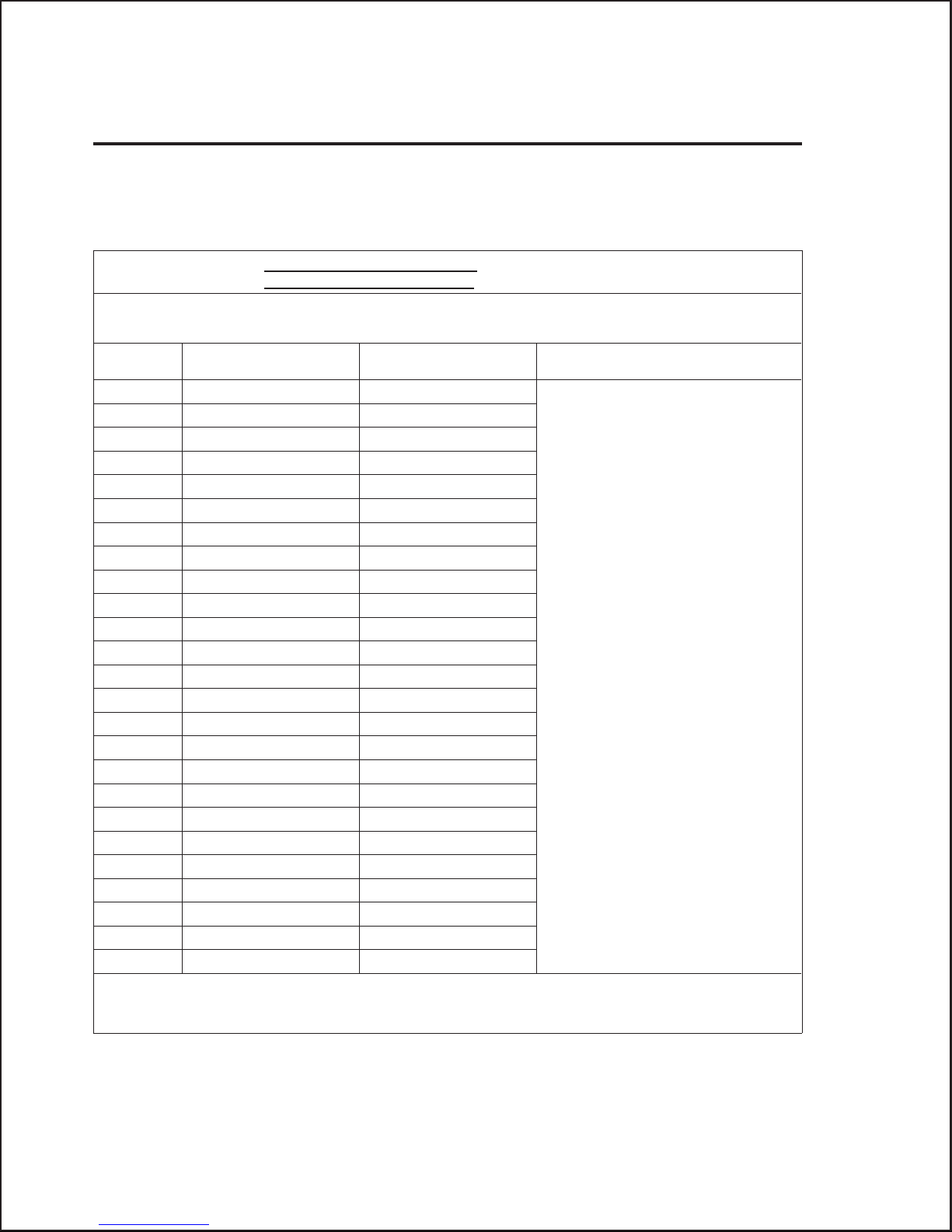
M-106E Reference Manual
Appendix 3: Programming Worksheets
Use the programming worksheets in this appendix to plan how you will
program and use the M-106E Remote Access Unit.
Incoming Telephone Number
Outgoing Telephone Number
SUMMARY, USER-SPECIFIC FUNCTIONS
User ID Password Timeout
1
2
3
4
5
6
7
8
9
10
11
12
13
14
15
16
17
18
19
20
21
22
23
24
25
Notes
TO ENSURE THE SECURITY OF YOURSYSTEM, Teltone recommendsthat you store this page and others referring
to programming of the unitin a safe place located away from the unit.
Page 50
Page 55

Appendix 3: Programming Worksheets
OTHER FUNCTIONS
Function Required Setting Function Required Setting
2 AnswerTone 20 Restrict Code Definition
#5
3 Level 20 Restrict Code Definition
#6
6 ReseizeDuration/Enable 20 Restrict Code Definition
#7
8 IdleDetect Time 20 Restrict Code Definition
#8
9 DialTone Detect 20 Restrict Code Definition
#9
10 Amplifier Gain 20 Restrict Code Definition
#10
11 Amplifier Sensitivity 21 Restrict Code
Assignment
12 Amplifier Direction 25 Prevent
13 Modem Detect 26 Type of Prevent
15 PasswordEnable/disable 27 Number of Attempts to
Activate
16 Detect Standard Ringing Only 28 Minutes Activated
17 Number of Rings 34 Reseize Control Code
18 Busy/Reorder Detect 35 Switchhook Flash Control
Code
20 RestrictCode Definition #1 36 Program Access Control
Code
20 RestrictCode Definition #2 37 Disconnect Control Code
20 Restrict Code Definition #3 40 Milliwatt Test
20 RestrictCode Definition #4 41 Interdigit Time
98 Remote Programming
TO ENSURE THE SECURITY OF YOURSYSTEM, Teltone recommendsthat you store this page and others referring
to programming of the unitin a safe place located away from the unit.
106E-101, Issue 1 Page 51
Page 56
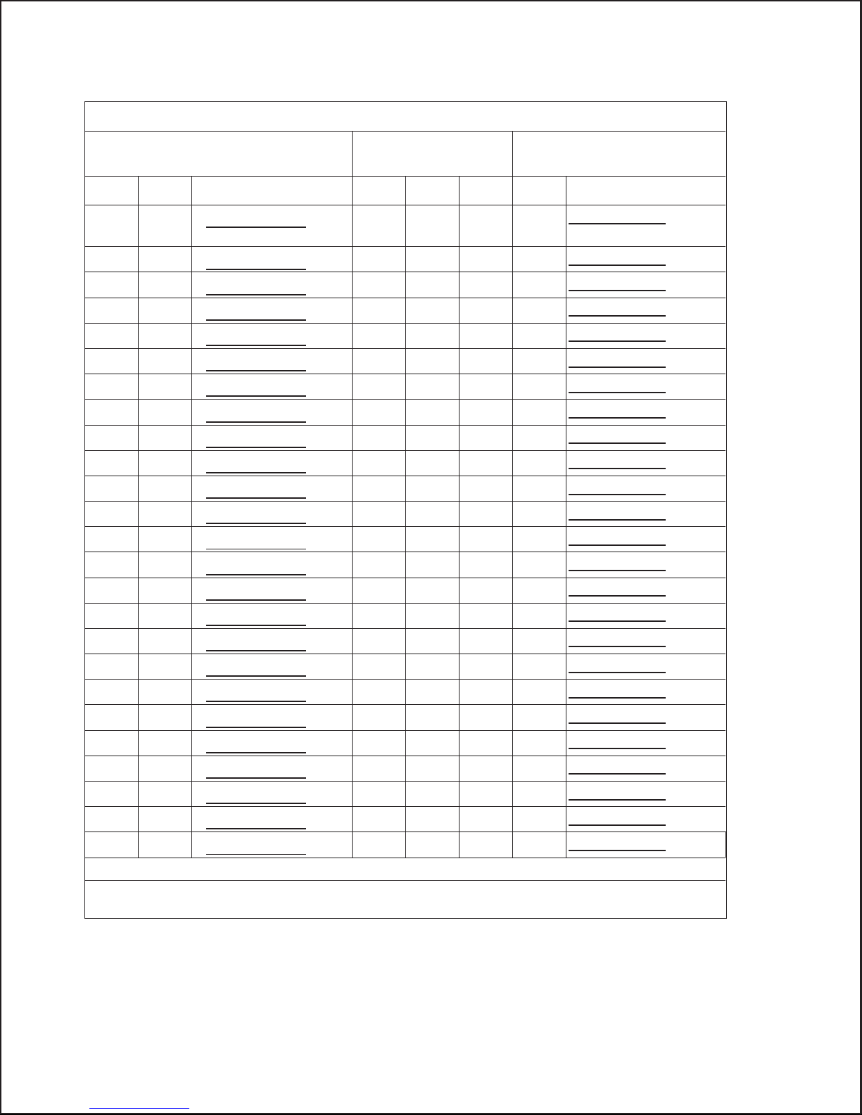
M-106E Reference Manual
PROGRAMMING USER PASSWORDS
Password programming
commands:
Func Usr Password Query Func Usr Usr Password
∗1
*1
∗ #
(Enter twice for User 1.)
∗1 ∗2 ∗ # ∗77 ∗1 ∗2#
∗1 ∗3 ∗ # ∗77 ∗1 ∗3#
∗1 ∗4 ∗ # ∗77 ∗1 ∗4#
∗1 ∗5 ∗ # ∗77 ∗1 ∗5#
∗1 ∗6 ∗ # ∗77 ∗1 ∗6#
∗1 ∗7 ∗ # ∗77 ∗1 ∗7#
∗1 ∗8 ∗ # ∗77 ∗1 ∗8#
∗1 ∗9 ∗ # ∗77 ∗1 ∗9#
∗1 ∗10 ∗ # ∗77 ∗1 ∗10#
∗1 ∗11 ∗ # ∗77 ∗1 ∗11#
∗1 ∗12 ∗ # ∗77 ∗1 ∗12#
∗1 ∗13 ∗ # ∗77 ∗1 ∗13#
∗1 ∗14 ∗ # ∗77 ∗1 ∗14#
∗1 ∗15 ∗ # ∗77 ∗1 ∗15#
∗1 ∗16 ∗ # ∗77 ∗1 ∗16#
∗1 ∗16 ∗ # ∗77 ∗1 ∗17#
∗1 ∗18 ∗ # ∗77 ∗1 ∗18#
∗1 ∗19 ∗ # ∗77 ∗1 ∗19#
∗1 ∗20 ∗ # ∗77 ∗1 ∗20#
∗1 ∗21 ∗ # ∗77 ∗1 ∗21#
∗1 ∗22 ∗ # ∗77 ∗1 ∗22#
∗1 ∗23 ∗ # ∗77 ∗1 ∗23#
∗1 ∗24 ∗ # ∗77 ∗1 ∗24#
∗1 ∗25 ∗ # ∗77 ∗1 ∗25#
Note: (b) = short beep tone; (bbb) = 3 short beeps
TO ENSURE THE SECURITY OF YOURSYSTEM, Teltone recommendsthat you store this page and others referring
to programming in a safe place locatedaway from the unit.
Password query
commands:
∗77 *1
*1# 1 (b)
2(b)
3(b)
4(b)
5(b)
6(b)
7(b)
8(b)
9(b)
10 (b)
11 (b)
12 (b)
13 (b)
14 (b)
15 (b)
16 (b)
17 (b)
18 (b)
19 (b)
20 (b)
21 (b)
22 (b)
23 (b)
24 (b)
25 (b)
Responses:
(bbb)
(bbb)
(bbb)
(bbb)
(bbb)
(bbb)
(bbb)
(bbb)
(bbb)
(bbb)
(bbb)
(bbb)
(bbb)
(bbb)
(bbb)
(bbb)
(bbb)
(bbb)
(bbb)
(bbb)
(bbb)
(bbb)
(bbb)
(bbb)
(bbb)
Page 52
Page 57
PROGRAMMING USER TIMEOUTS
Appendix 3: Programming Worksheets
Timeout assignment
commands:
Func Usr Time Query Func Usr Usr Time
∗4 ∗1 ∗ # ∗77 ∗4 ∗1#
∗4 ∗2 ∗ # ∗77 ∗4 ∗2#
∗4 ∗3 ∗ # ∗77 ∗4 ∗3#
∗4 ∗4 ∗ # ∗77 ∗4 ∗4#
∗4 ∗5 ∗ # ∗77 ∗4 ∗5#
∗4 ∗6 ∗ # ∗77 ∗4 ∗6#
∗4 ∗7 ∗ # ∗77 ∗4 ∗7#
∗4 ∗8 ∗ # ∗77 ∗4 ∗8#
∗4 ∗9 ∗ # ∗77 ∗4 ∗9#
∗4 ∗10 ∗ # ∗77 ∗4 ∗10#
∗4 ∗11 ∗ # ∗77 ∗4 ∗11#
∗4 ∗12 ∗ # ∗77 ∗4 ∗12#
∗4 ∗13 ∗ # ∗77 ∗4 ∗13#
∗4 ∗14 ∗ # ∗77 ∗4 ∗14#
∗4 ∗15 ∗ # ∗77 ∗4 ∗15#
∗4 ∗16 ∗ # ∗77 ∗4 ∗16#
∗4 ∗17 ∗ # ∗77 ∗4 ∗17#
∗4 ∗18 ∗ # ∗77 ∗4 ∗18#
∗4 ∗19 ∗ # ∗77 ∗4 ∗19#
∗4 ∗20 ∗ # ∗77 ∗4 ∗20#
∗4 ∗21 ∗ # ∗77 ∗4 ∗21#
∗4 ∗22 ∗ # ∗77 ∗4 ∗22#
∗4 ∗23 ∗ # ∗77 ∗4 ∗23#
∗4 ∗24 ∗ # ∗77 ∗4 ∗24#
∗4 ∗25 ∗ # ∗77 ∗4 ∗25#
Note: (b) = short beep tone; (bbb) = 3 short beeps
TO ENSURE THE SECURITY OF YOURSYSTEM, Teltone recommendsthat you store this page and others referring
to programming in a safe place locatedaway from the unit.
Timeout query
commands:
1(b)
2(b)
3(b)
4(b)
5(b)
6(b)
7(b)
8(b)
9(b)
10 (b)
11 (b)
12 (b)
13 (b)
14 (b)
15 (b)
16 (b)
17 (b)
18 (b)
19 (b)
20 (b)
21 (b)
22 (b)
23 (b)
24 (b)
25 (b)
Responses:
(bbb)
(bbb)
(bbb)
(bbb)
(bbb)
(bbb)
(bbb)
(bbb)
(bbb)
(bbb)
(bbb)
(bbb)
(bbb)
(bbb)
(bbb)
(bbb)
(bbb)
(bbb)
(bbb)
(bbb)
(bbb)
(bbb)
(bbb)
(bbb)
(bbb)
106E-101, Issue 1 Page 53
Page 58

M-106E Reference Manual
Appendix 4: Programming Quick Reference
To Enable Remote Programming (On-Site):
• Set front panel switch to PROGRAM until the green light flashes quickly.
• Call the M-106 using a DTMF phone. When it responds with 3 beeps, you
are in program mode. Enter:
*98*1#
• To activate security code for User 1, enter: *1*1*NN...N#*1*1*NN...N#
where: NN...N may be 3 to 10 digits
• Press # # and hang up. The unit can now be programmed remotely.
• Press the front panel switch to READY until the green light flashes.
To Enter Programming Mode:
On-Site Programming
Complete the two steps below if you are on site or can have someone else on
site assist you. If not, see the Remote Programming instructions.
• Set front panel switch to PROGRAM until the green light flashes quickly.
• Call the unit from a DTMF telephone. When the M-106E responds with 3
beeps, you are in program mode.
Remote Programming (Password Access Enabled)
• Call unit using a DTMF telephone.
• When you hear an answer tone, enter the User 1 password, followed by #.
• When the M-106E responds with 3 beeps, you are in program mode.
Remote Programming (Password Access Disabled)
• Call the M-106E using a DTMF telephone. When you hear dial tone, enter
programming access code (default #*).
• When dial tone ends and answer tone is heard, enter the User 1 password,
followed by #. When the M-106E responds with 3 beeps, you are in
programming mode.
• When you finish programming, either enter the disconnect control code
(default # #) and hang up or enter the reseize control code (default **) to
place a call through the unit.
Page 54
Page 59

Function Command Description Default
Password assignment
∗1∗UU∗NN...N#
(Enter twice for User 1.)
∗1∗UU#
(Enter twice for User 1.)
Answer tone
∗2∗1#
∗2∗0#
Level
User timeout
Reseize Duration *6*TT# TT=0, disabled
Idle detect (silent)
Dial tone detect time
Amplifier gain
Amplifier sensitivity
Amplifier direction
Modem detect
∗3∗L#
∗4∗UU∗TT#
∗8∗TT#
∗9∗TT#
∗10∗NN#
∗11∗S#
∗12∗D#
∗13*1#
∗13*0#
Password enable
∗15∗1#
∗15∗0#
Detect standard ringonly
∗16∗1#
∗16∗0#
Setnumberofrings
Busy/reorderdetect
RestrictCode Definition
Restrict Code Assignment
Prevent
∗17∗RR#
∗18∗TT#
∗20∗C∗DDDD#
∗
20∗C#
∗21∗UU∗C...C#
∗25∗1#
∗25∗0#
UU = user (1-25),
NN...N = password (3-10 digits)
removes password from User UU
enabled enabled
disabled
L=level=1:-162dBm;2:-10±2dBm;
3: -4 ±2dBm
UU = user ID (1-25);
TT = timeout = 0-99 minutes
5-30
TT = time (0-99 minutes) TT = 0 (disabled)
TT = time (0, 5-20 seconds) TT = 0 (disabled)
NN = gain in dB(0-15; 0 = disabled) NN = 5
S = sensitivity (0-5) S = 0
S = 1 = caller sensitivity
S = 2 = office sensitivity
S = 3 = enhancedsensitivity
S = 4 = caller + enhanced sensitivity
S = 5 = office + enhanced sensitivity
D = direction control (0-3) D = 1 (enabled)
D = 1 = off after first digit buttons up
D = 2 = off after buttons up on each digit
D=3=offafterbuttonsupon#
enabled disabled
disabled
enabled enabled
disabled
enabled disabled
disabled
RR = number of rin gs before answer (1-16) RR = 1
TT = 0 = disabled
TT=1-4=notvalid
TT = 5-20 = time to disconnect (5-20 seconds)
C = code (0-9); DDDD = restrict digit string (1-5
digits); * = wildcard
Deletes digits from code C
UU = usr (1-25); C = code as defined above (0-9) none
enabled
disabled
Appendix 4: Programming Quick Reference
No passwords
L=2
TT = 99
20
(no sensitivity)
TT = 0
no codes
disabled
106E-101, Issue 1 Page 55
Page 60

M-106E Reference Manual
Function Command Description Default
Response to callers during
prevent
Number of invalid
attempts before prevent
Prevent duration
Reseize Code
SwitchHook Flash Code
ProgramAccess Code
Disconnect Code
Milliwatt test release
Interdigit Time
Programming query
Version query
Remote programming
Restore defaults
∗26∗R#
∗27∗NN#
∗28∗MM#
∗34∗N∗DDD#
R=0=errortone
R = 1 = ignoreringing
R = 2 = ignore passwords
NN = number of attempts (1-20) 5
MM = 1-20 = minutesenabled 5
N= number of digits in the code
DDD= the control code, of 0, 2 or 3 digits(0-9,
or #)
N=0, disabled
R=0 (error tone)
∗∗
∗
∗35∗N∗DDD# ∗#
∗36∗N∗DDD#
∗37∗N∗DDD#
∗40∗TTT#
∗41∗DD#
∗77∗FF∗NN...N#
∗90#
∗98∗1#
∗98∗0#
N= number of digits in the code
DDD= the control code, canbe 0, 2 or 3 digits
(0-9,
∗or #)
N= number of digits in the code
DDD= the control code, canbe 0, 2 or 3 digits
(0-9,
∗or #)
TTT = tone duration time to disconnect
(0-300 seconds)
DD=interdigit time in 1/10second (1-20) DD=10
FF = function; NN...N =information
Software version query
enabled disabled
disabled
#∗
##
TTT = 15
∗99#*99#
Page 56
Page 61

Appendix 5: Index
A
Answer tone 8, 55
Enable/disable 25
Level setting 26
B
Busy/Reorder
Detect 28, 55
Appendix 5: Index
Prevent 9
Programmable Control Codes 7
Remote Programming 10
Reseize 8
Rings Before Answer 9
Voice Verification 9
G
Ground Start 2, 7
C
Call
Duration 8
Compatibility 4
Connections
Power and line 6
Control code
Interdigit time 32
Control codes
Disconnect 2
Programming 7
Reseize 2
Switchhook flash 2
Customers
Canadian 39
United States 38
D
Defaults
Restore 33, 56
Dial Tone
Absence of 2
Detect Time 55
Detection of 27
Disconnect 31, 56
E
Entering control codes
How to 2
I
Idle detect
Time 27, 55
Interdigit Time 32, 56
L
LED 6
Level55
Line Requirements 7
Loop or ground start 2
Loop Start 7
M
M-106E
Dimensions 6
LED 6
Line requirements 7
Operation 3
Power 7
Manual
revision information 2
Material Return Authorization 38, 39, 41
Milliwatt test retrial 32, 56
Modem detect
Enable/disable 37, 55
Mounting
Universal Mounting Bracket 12
Universal Mounting Shelf 13
Wall Mounting Strap 11
F
Features
Answer Tone 8
Busy/Reorder Disconnect 9
Switchhook Flash 8
Detect Standard Ring Only 9
Dial Tone Detect 9
Idle Detect 8
Manual Disconnect 8
Milliwatt Detect 9
Non-volatile Memory 9
Passwords 7
106E-101, Issue 1 Page 57
N
Number of rings
Set 28, 55
O
Operation
With password 16, 21
Without passwords 15
Ordering information
Accessories 45
Basic units 45
Page 62

M-106E Reference Manual
P
Password
Access enable/disable 27
Passwords 55
Assigning 20, 25, 55
Followed by # 7
Tips 5
Polarity 7
Power
Input 7
Prevent 30
attempts before 56
Duration 31, 56
Prevents
Attempts before 30
Programming
Command format 24
query 32
Programming mode
Access 31, 56
Exit 33
Q
Query 32, 33
Programming 56
Version 56
R
Remote programming 56
Enable/disable 33
REN
All devices 5
Reseize 8
Code 31, 56
On-hook time 26
Reseize
Duration 55
Restrict Code
Definition 55
Restrict Codes 5, 8
Assigning 55
Tips 6
Return procedures
Canadian customers 39
U.S. customers 38
Ringing
Detect standard 55
S
Standard ringing
Detect only 28
Switchhook flash 8
Code 31, 56
T
Technical Support 40
Test tones 32
Toll fraud 38
Troubleshooting
Continuous dial tone 43
IN LED lights, drops 43
No answer 41, 43
No answer tone 42
no reseize 43
Wrong/missing digits 44
U
User Quick Reference 58, 59, 61
User timeout
Setting 26, 55
Using This Manual
Manual conventions 1
Revision information 2
V
Version
Query 33
Voice Switched Amplifier
Automatic Level Control 34
Data Disable 34
Gain Direction Control 34, 55
Gain level 34
Ordering option 10
query 37
Sensistivity options 35
Sensitivity 35
Sensitivity 55
W
Warranty 38
Page 58
Page 63

Appendix 6: User Quick Reference
The instructions on the following pages will enable the user to place calls
through the M-106E. Please complete the steps below before photocopying the
next few pages and giving them to the users.
Step 1: Review the Quick Reference
• Read through the information, noting anything that varies with your
application.
Step 2: Have you changed the control code defaults?
• If you have changed the defaults for any of the control codes, write the
new values in the blank lines provided.
Step 3: Indicate which instructions the users should follow
• Place a check in the boxes next to each instruction the users should follow.
Appendix 6: User Quick Reference
Step 4: Security
• Instruct the users to keep their copies in secure places as these instructions
explain how to access the system.
Step 5: Distribution
• Distribute copies of the Quick Reference to the users. Please keep a copy
for yourself for future reference.
106E-101, Issue 1 Page 59
Page 64

M-106E Reference Manual
Quick Reference
These instructions will enable you to complete and receive calls through the
M-106E. Follow only the instructions with
If a command has a default, it is shown in () immediately following a blank
line. If the default code is not used, the system administrator will enter other
values on the blank line. If the administrator does not write in a new control
code, enter the code in ().
Your M-106E unit is programmed to include the following:
Security code: Answer Tone:
❏ enabled ❏ enabled
❏ disabled ❏ disabled
Simulated switchhook flash Retrial capability:
❏
enabled, code _____(∗#)
❏ disabled ❏ disabled
Remote disconnect _____(# #) Elapsed time disconnect:
❏ required ❏ after (0-99) _____ minutes
❏ not required ❏ disabled
❏
enabled, code_______(∗∗)
Page 60
Page 65

Appendix 6: User Quick Reference
To Place a Call
Step 1: Call the M-106E
• Dial the M-106E assigned telephone number:
___________________________________
❏ With answer tone and password enabled:
• You will hear a 2-second tone.
• Enter the password, followed by # within 15 seconds after the tone ends.
You will hear dial tone if the password is accepted.
❏ With answer tone disabled and and password enabled:
• Wait three seconds after the unit answers and enter the password,
followed by #, within 15 seconds. You will hear dial tone if the password
was accepted.
❏ With password disabled:
• You will hear dial tone upon accessing the unit.
Step 2: Complete the call
• When you hear dial tone, you can place a call. if dial tone persists and the
call does not go through, attempt the call again. If the call still does not go
through, the M-106E may require a change of configuration, or
transmission losses prevent the use of the M-106E from your remote
location.
106E-101, Issue 1 Page 61
Page 66

M-106E Reference Manual
Special Procedures
Use of any of the following features requires special procedures as indicated:
Retrial:
To place another call without disconnecting from the M-106E or to make a
retrial after a dialing error, no answer, or busy, enter **. You should hear dial
tone in about 5 seconds.
Switchhook flash:
If the M-106E has this feature enabled, you can cause the M-106E to generate a
switchhook flash (for example, to set up a conference call, or to signal the PBX
attendant) by entering *#.
Remote disconnect:
Enter # # before hanging up if your M-106E requires a remote disconnect
signal.
User Timeout:
If the unit is programmed for automatic disconnection after 1 to 99 minutes,
you will hear a warning tone 16 seconds before disconnection. You must redial
the M-106E if your call was not concluded.
Page 62
 Loading...