

Page 1

InfoLink Data Switch
DS-104 and DS-108
Product Manual
40-400-00022, Rev. B
Page 2

Note
This manual covers Models DS-104-A-02 and DS-108-A-02.
Copyright Notice
Copyright © 1993 - 2003 Teltone Corporation
All Rights Reserved
Trademarks
Teltone is a registered trademark of Teltone Corporation.
Windows is a registered trademark of Microsoft Corporation.
Other company and product names may be trademarks or
registered trademarks of their respective owners.
Teltone Corporation
Bothell, Washington 98021 USA
Customer Service: 425-951-3388
Technical Support: 425-951-3390
Fax: 425-487-2288
Email: info@teltone.com
Website: www.teltone.com
40-400-00022, Rev. B
Page 3

Contents
U.S. FCC Compliance Information.................................................................................................... 2
Chapter 1 - General Description ....................................................................................................... 3
Chapter 2 - Getting Started............................................................................................................... 4
Using this manual ...................................................................................................................... 4
DS-100 Package ........................................................................................................................ 5
Chapter 3 - Overview ........................................................................................................................ 6
User Ports.................................................................................................................................. 6
Local Maintenance Port............................................................................................................. 6
Incoming Traffic.......................................................................................................................... 6
Remote Programming................................................................................................................ 6
Routing Commands ................................................................................................................... 6
Emergency Interrupt Input ......................................................................................................... 7
No Priority .................................................................................................................................. 7
Total Priority............................................................................................................................... 7
Data Routing.............................................................................................................................. 7
Transfer Data Connection to Another User Port ........................................................................ 7
Outgoing Traffic, Data Switch Idle..............................................................................................7
Outgoing Traffic, Data Switch Active.......................................................................................... 8
Disconnect Procedure ............................................................................................................... 8
Data Transfer Inactivity Time-out ...............................................................................................8
Loss of Power ............................................................................................................................ 8
Version 2.00 Upgrade ................................................................................................................ 8
Chapter 4 - Typical Applications ....................................................................................................... 9
Figure 1 Single Stand Alone Configuration .............................................................................. 9
Figure 2 Cascade Configuration............................................................................................. 10
Figure 3 System Configuration with SLSS and DS-100 ......................................................... 1 1
Figure 4 System Configuration with CIUS and DS-100.......................................................... 12
Figure 5 System Configuration with CIUS, SLSS and DS-100............................................... 12
Chapter 5 - Installation.................................................................................................................... 13
Figure 6 System Installation ....................................................................................................14
Chapter 6 - Programming and Default Settings.............................................................................. 15
Programming Rules ................................................................................................................. 15
Programming Access ............................................................................................................... 15
Modem Configuration .............................................................................................................. 16
Detailed Programming Information.......................................................................................... 17
Chapter 7 - DS-100 Flash ROM Upgrade Procedures ................................................................... 32
How to download from the Web Site:....................................................................................... 32
Loading the software into the DS-100. .................................................................................... 32
Chapter 8 - Front Panel Indicators and Controls ............................................................................ 36
Power/ Status LED.............................................................................................................. ..... 36
Alarm LED ............................................................................................................................... 36
Modem Port Transmit and Receive LEDs................................................................................ 36
User Port Indicator LEDs ......................................................................................................... 36
Chapter 9 - Connectors and Terminal Strips................................................................................... 3 7
Figure 7 Front and Rear Panels ............................................................................................. 37
Chapter 10 - Data Retention........................................................................................................... 38
Programming Verification......................................................................................................... 38
Factory and Customer Defined Default Settings ..................................................................... 38
Chapter 11 - Warranty and Service ................................................................................................ 39
Warranty Information ............................................................................................................... 39
Technical Suppor t .................................................................................................................... 39
Return Procedures .................................................................................................................. 39
Appendix 1 - Ordering Information ................................................................................................. 40
Appendix 2 - Specifications .................................................................................................... ........ 41
Electrical .................................................................................................................................. 41
Mechanical............................................................................................................................... 41
Environmental.......................................................................................................................... 42
Regulatory ............................................................................................................................... 4 2
Appendix 3 - Glossary .................................................................................................................... 43
Index ............................................................................................................................................... 46
40-400-00022 Rev. B 1
Page 4

U.S. FCC Compliance Information
Part 15 Class A Notice: This equipment has been tested and f ound to
comply with the limits for a Class A digital device , pursuant to Part 15 of the
FCC Rules. These limits are designed to provide reasonable protection
against harmful interference when the equipment is operated in a commercial environment. This equipment generates, uses, and can radiate radio
frequency energy and, if not installed and used in accordance with the
instruction manual, may cause harmful interference to radio communications.
Operation of this equipment in a residential area is likely to cause harmful
interference, in which case the user will be required to correct the interf erence at his own expense.
2 40-400-00022 Rev. B
Page 5

Chapter 1 - General Description
The Teltone DS-100 Series Data Switch allows users to communicate with
up to 64 Intelligent Electronic Devices (IEDs) through a single, RS-232 serial
connection. The DS-100 is available in 4 and 8 port versions and has been
designed to be operated independently or as part of a distribution automation
system. The unit has been engineered to withstand the rigors of substation
and other hazardous environments, meeting IEEE C37.901-1989SWC surge
withstand capability and FCC Part 15 Class A requirements for use in
industrial/business applications.
The DS-100's ability to communicate with multiple IEDs from a single originating call, results in real time savings when sev eral IEDs must be polled at
the same time. The unit has been designed to work in conjunction with the
family of Teltone Line Sharing Switches and Cellular Interface Units. This
allows users to use each device in a stand alone mode, or together in a
system configuration.
Depending on the application, some users will find it more cost effective to
install the DS-100 with one modem situated in front of the unit instead of
putting a modem in front of each IED. This also simplifies potential protocol
conflicts where different manuf acturers' modems are used with different IEDs
requiring unique modem register settings. The DS-100 series also supplies
±12 VDC output terminals, providing con v enient po wer access for external
12 VDC pow ered modems and ±12 VDC for fiber isolators.
The DS-100 has a wide power input operating range between 42 to 150 VDC
or 90 to 120 VAC.
Product upgrades will become availab le periodically. The oper ation of the
DS-100 allows for upgrades using an Internal Flash ROM. Review Chapters
2 and 7 for more details.
40-400-00022 Rev. B 3
Page 6

Chapter 2 - Getting Started
Using this manual
This reference manual provides the user/installer with step-by-step instructions for installing and programming the DS-100. Take time to familiarize
yourself with this manual. This will make the installation process go more
smoothly.
The following is a brief description of the chapters in this manual.
Chapter 1 - General Description
Chapter 2 - Getting Started
Chapter 3 - Overview
This section describes how the DS-100 works.
Chapter 4 - Typical Applications
This section contains diagrams showing some typical applications using the
DS-100.
Chapter 5 - Installation
This section describes how to rack mount the DS-100, connect the DS-100
to power , and connect other equipment to the DS-100.
Chapter 6 - Programming and Default Settings
This section describes the default settings, as well as how to progr am the
DS-100 through menu commands.
Chapter 7 - DS-100 Flash ROM Upgrade Procedures
Describes how to download EEPROM upgrade to the DS-100 using diff erent
applications.
Chapter 8 - Front Panel and Indicator Contr ols
Explains LED status conditions.
Chapter 9 - Connectors and Terminal Strips
Describes each connection on the front and rear panel of the DS-100.
Chapter 10 - Data Retention
How data is stored in the DS-100.
Chapter 11 - Warranty and Service
What to do in the event you have a def ective unit.
4 40-400-00022 Rev. B
Page 7

Appendix 1 - Ordering Information
Appendix 2- Specifications
Electrical, mechanical, environmental, and regulatory specifications.
Appendix 3 - Glossary
Explains terminology mentioned in this manual.
Index.
DS-100 Package
Unpack the DS-100 and verify that you have received the following:
• DS-100 unit
• Modem installation kit, which includes 2 fastening pads and a modem
cable.
• Hardware installation kit, which includes a spare fuse, mounting brackets, screws, and w ashers.
If any of these items are damaged or missing, contact Teltone Corporation
Customer Service department. See Chapter 11, W arr anty and Service
chapter for further information.
40-400-00022 Rev. B 5
Page 8

Chapter 3 - Overview
User Ports
The four or eight DCE User ports will support between 300 - 38,400 bps
asynchronous data transmission rates.
Local Maintenance Port
The Local Maintenance port accepts a terminal or terminal emulator. No
password is required for prog ramming access through this port. Programming access will be a lower priority process than any ongoing data transfer.
Incoming T raffic
Incoming traffic to the DS-100 is answered b y the modem which must be
configured for auto-answer. The DS-100 looks for DCD (carrier detect) from
the modem to know that a call has been received. It then starts monitoring
the data from the modem for a system passw ord (if one is prog r ammed)
followed b y a transfer code. By default, there is no access password.
Remote Programming
Remote programming access can be performed through the Modem input
port. A transf er code sent to this port will access programming mode by
sending “ab0” where “ab” is the default code. Any initial remote access to the
menu via the Modem port will require (in default configuration) a programming password, with “teltone” being the default password. Once access is
gained, an inactivity timer will terminate programming connection after a
programmable (def ault=3) number of min utes of no activity.
Routing Commands
The DS-100 monitors the data flow into the Modem port for data switch
commands. To enter a command, there m ust be a pause in the data stream
into the Modem port, followed by a 3-character command string, follow ed b y
another pause in data. All commands are 3 characters in length, and all 3
characters must be entered within a 2 second period. The minimum length
for the pauses before and after the command string are user programmable
from 0.1 to 2.0 seconds, in 0.1 second increments.
If the string is not a valid command, pauses too short, or the 3 characters are
not entered within a 2 second period, the string will be forwarded to the
currently selected User port. If the string is a valid command, it is not
forwarded to the User port.
The DS-100 recognizes the following commands:
ab0 Connects to maintenance menus for remote configuration
ab1 thru ab8 Connects the Modem port to the selected User port
ab? Reports which User port is currently connected to the
Modem port
The “ab” prefix f or the commands is user prog rammable.
6 40-400-00022 Rev. B
Page 9

Emergency Interrupt Input
When an AC or DC voltage is applied to this input, located on the rear panel,
the unit will terminate an on-going transfer by dropping DTR to the modem
port. The unit sends a configur ation string to the modem to prepare it for the
next call. The configur ation string is user programmable. The Interrupt
feature is disabled in the f actory default setting. It allows the user a means to
remotely abort a lengthy data transfer when another operation is desired.
Users can apply DC voltage through auxiliary relay on “B” version of
Teltone’s Substation Line Sharing Switch, (SLSS - must be on another
central office line), through a SCADA system or other intelligent de vice.
No Priority
In this mode, no port will be able to interrupt a data transfer on another port.
No Priority is the default factory setting.
Total Priority
In this mode, User P ort 1 is the highest priority port. If another User port is
active, its activity will be terminated to allow User port 1’s request to be
serviced. User port 2 has the second highest port priority. User port 8 has
the lowest priority. When a higher priority port interrupts a data transfer, the
unit will not initiate any action to reestablish the original transfer.
Data Routing
Incoming traffic is initiated when the DS-100 sees carrier detect go active on
the Modem input port. When incoming tr affic arriv es at the modem port,
(modem must be configured for auto-answ er) the unit may expect to receive
an access password fo llowed by a routing command (transf er code). If the
command is successful, the modem port will be logically connected to the
specified User port. The modem can be progr ammed from the Local Maintenance port.
Transfer Data Connection to Another User Port
When there is a pause in data flow into the Modem port, the unit will monitor
the next set of characters to see if they are a v alid data switch command. If
the string is valid and of correct length, the Modem port will be logically
connected to the newly selected User port. If the string is not valid, the unit
will forward the string to the currently selected User port. The required
pause duration is programmable in 0.1 second increments . Factory default is
>1.0 second.
Outgoing Traffic, Data Switch Idle
The unit expects either DTR or RTS to go active as a request for service.
The unit is programmable to select which of these signal(s) will be considered a request for service. The unit will respond by logically connecting the
requesting device to the Modem port.
40-400-00022 Rev. B 7
Page 10

Outgoing Traffic, Data Switch Active
If there is a request for service and the unit is set to No Priority default, and
the unit is active on another User port, the unit will not respond to the request
until it is idle. If the unit is set for Total Priority, and a higher priority port
requests service, the unit will abort the current transfer, drop DTR to the
Modem port, and wait until the Modem port is ready for a new tr ansf er.
When the unit is ready to support the next call, it will logically connect to the
Modem port.
Disconnect Procedure
Incoming calls are disconnected when DCD goes inactive on the Modem
input port. Outgoing calls are disconnected when DTR or RTS (whiche ver
was used to originate the call) goes inactive. When either the Modem input
port or active User port has their control lines go inactive, the unit will go idle.
Data T ransfer Inactivity Time-out
The Data Transfer Inactivity time-out can be set betw een 1 and 10 min utes in
1 minute intervals. The default time-out is 3 minutes. The user can also
program the unit for no activity time-out.
Loss of Power
The unit will be totally inoperative when pow ered do wn. The only output will
be an alarm contact closure.
Version 2.00 Upgrade
The Version 2.00 upgrade adds the following features:
• expanded modem initialization string from 25 to 50 characters
• up to 64 port expansion using a single transfer code (cascading)
• site Sign On message operation
• case sensitive transf er code operation
• default port operaton
• port rollover operation
• reconnect to last accessed port operation
• port time-out alarm enable/disable
AC Power
Teltone part numbers 250-00204-05 (DS-104) and 250-00204-06 (DS-108)
and later are properly labeled for 90 - 120 VAC power use. Earlier models
are also able to operate with AC power, but are not correctly labeled. Ref er to
Figure 7 for AC connections .
8 40-400-00022 Rev. B
Page 11
Chapter 4 - Typical Applications
Electric utilities are continually searching for wa ys to lo wer oper ating costs,
improve efficiencies, and pro vide better customer service. Various distribution automation techniques are quickly being introduced and embraced. This
is causing a proliferation of IEDs, such as electronic meters, relays and
digital fault recorders to be installed into electrical substations. Due to
different IED manufacturers using diff erent protocols, communicating with
these devices can be difficult. In addition, if an analog telephone line is used
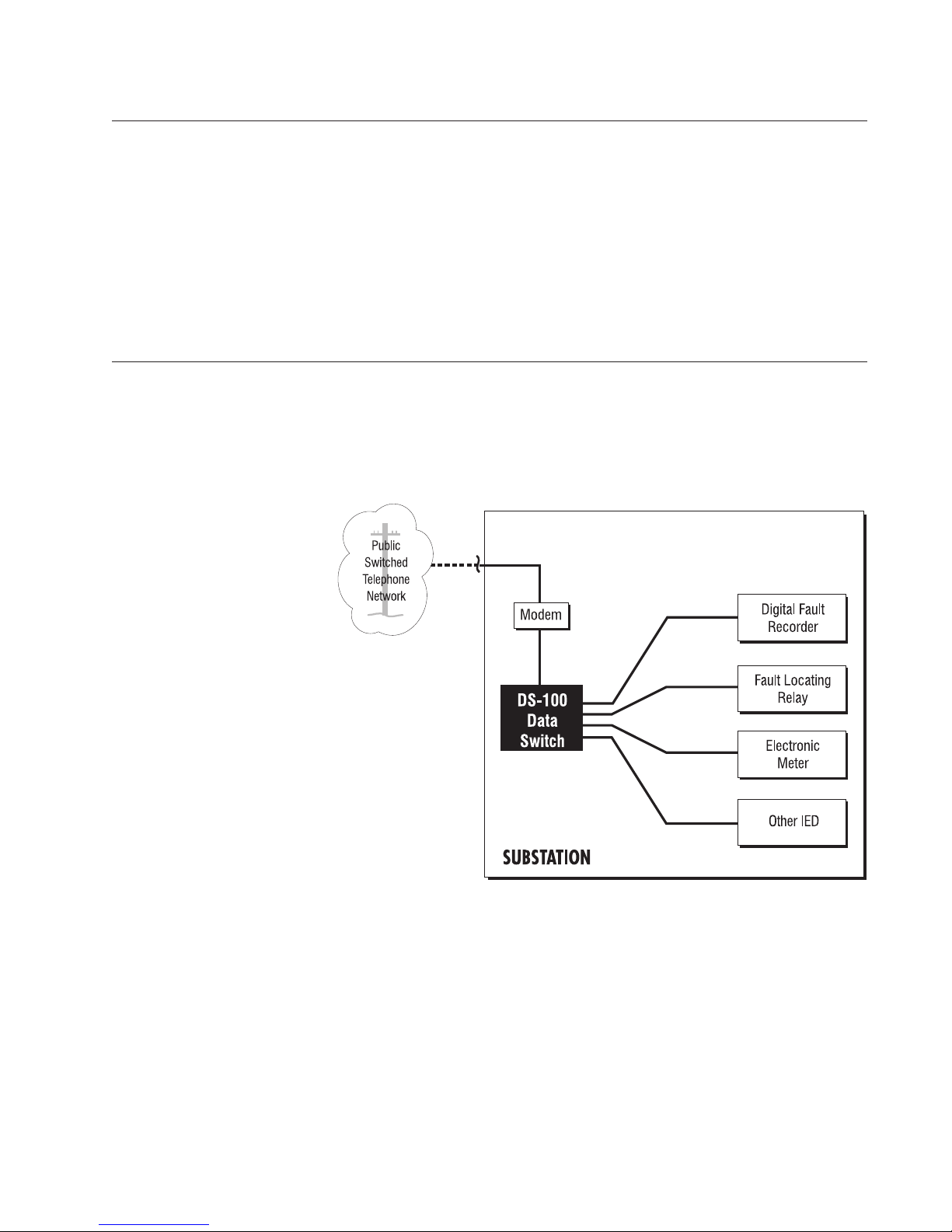
as the primary communication link, each IED requires its own modem to
convert from an analog signal to a digital one.
Figure 1 Single Stand Alone Configuration
To avoid the expense of using multiple modems , a user can install the DS100 in front of the IEDs:
40-400-00022 Rev. B 9
Page 12
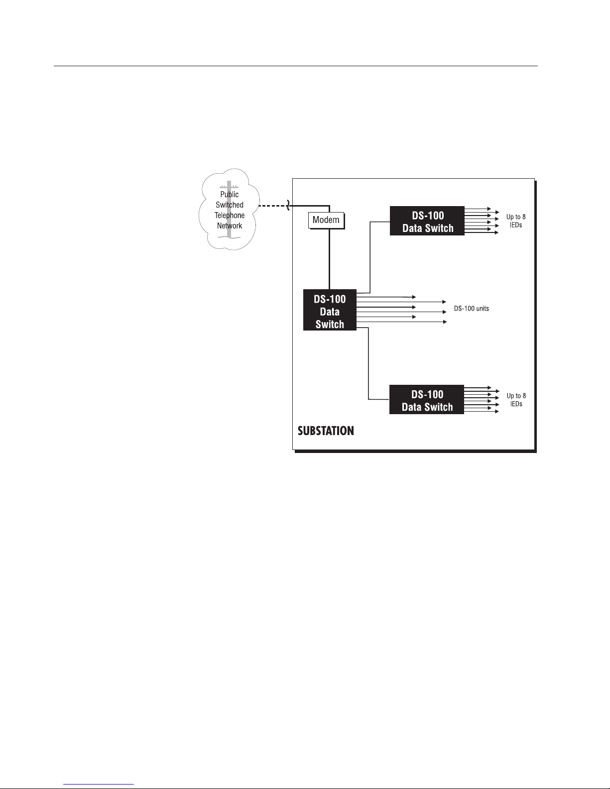
Figure 2 Cascade Configuration
The user can have up to 64 connections by connecting up to 8 DS-100 units
behind a primary DS-100:
10 40-400-00022 Rev. B
Page 13
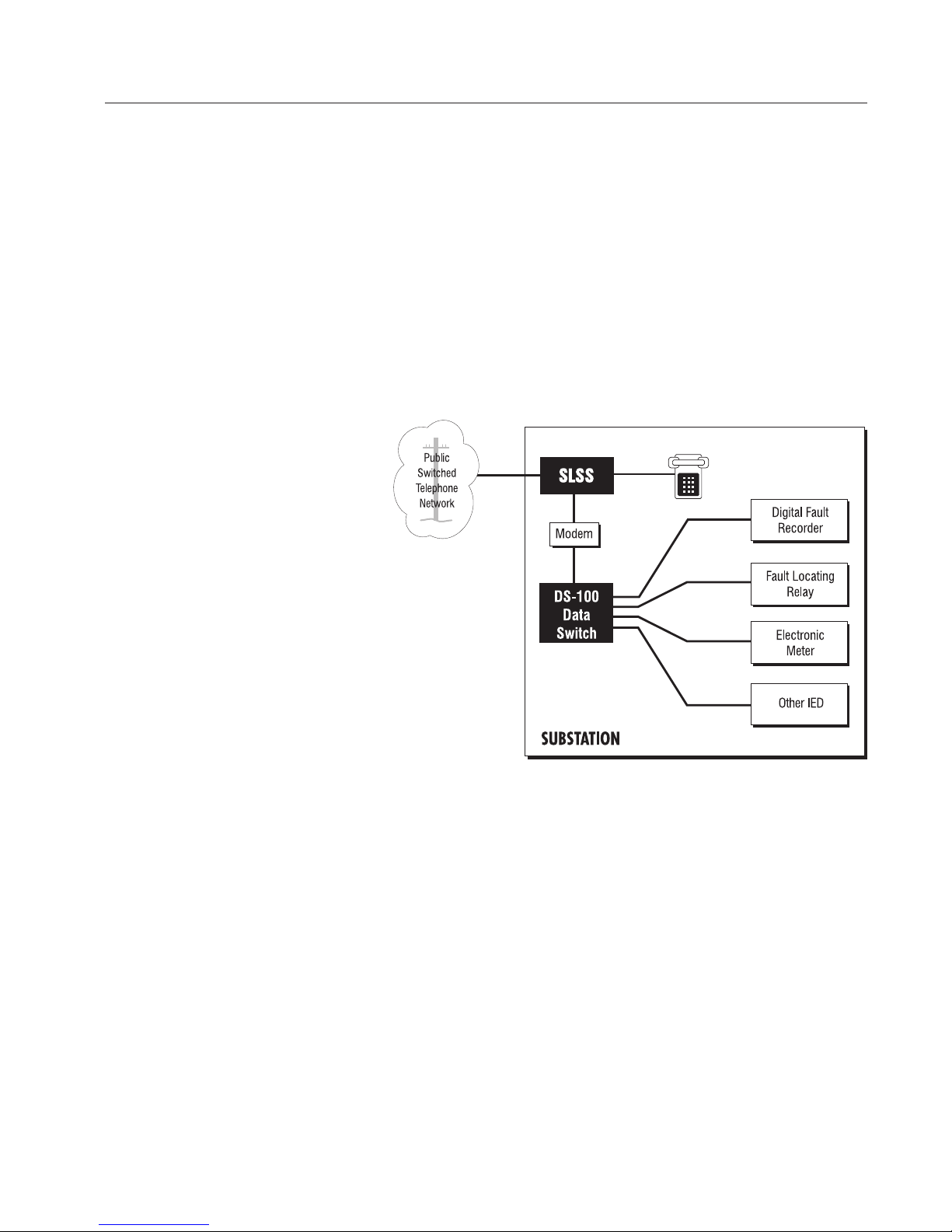
Figure 3 System Configuration with SLSS and DS-100
The DS-100 has been designed to work in conjunction with the Teltone family
of Line Sharing Switches and Cellular Interface Units. Depending on the
application, a combination of these devices can provide an efficient, cost
effectiv e system solution.
If telephone service is needed or desired, users can install the Teltone Substation Line Sharing Switch (SLSS) and modem in front of the DS-100. This
configuration enables users to communicate with multiple IEDs through the
DS-100, saving on multiple modem expense while pro viding cost sa ving
phone service:
40-400-00022 Rev. B 11
Page 14
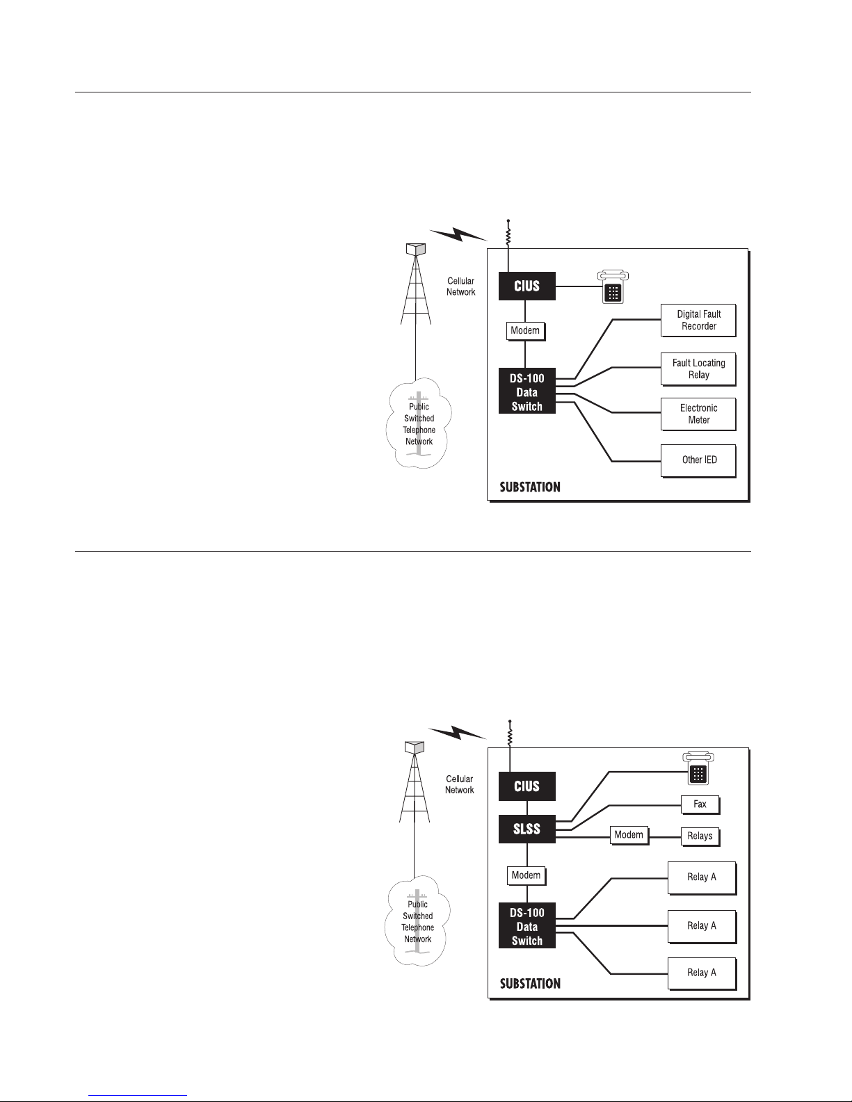
Figure 4 System Configuration with CIUS and DS-100
If cellular service is needed or desired, users can install Teltone’s Cellular
Interface Unit for Substations (CIUS) and cellular modem in conjunction with
the DS-100. This allows users to take advantage of low cost, reliable, easily
installed cellular communications as a medium between their host/ polling
location and their IEDs:
Figure 5 System Configuration with CIUS, SLSS and DS-100
If users have a need or desire to use a single cellular circuit for voice and
data to communicate with multiple IEDs, the user can combine Teltone’s
CIUS, SLSS and DS-100. This provides a cost competitive, easily installed
and reliable distribution automation system solution:
12 40-400-00022 Rev. B
Page 15

Chapter 5 - Installation
1. If rac k mounting, attach the mounting ears to both sides of the DS-100
using the enclosed screws. Unit will fit in either a 19" or 23" rack and can be
flush or center mounted.
2. Position unit into rack, aligning mounting ear holes with rack holes.
Secure unit into place by affixing screws with corresponding washers.
3. To power the modem (not ncluded) from the DS-100, insert the bayonet
end of the modem power cable into the modem. Assuming your modem
operates off 12 VDC , insert the ribbed or marked lead into the “+12V” terminal. (You may w ant to test the polarity of the modem power leads before
connecting.) Insert the other lead into the ground terminal marked, “GND”.
Fiber optic isolators normally used the +12 VDC and -12 VDC connections.
*NOTE* The -12 VDC connection is NOT recommended for powering modem
installations.
4. Connect the modem to the DS-100 b y attaching a DB-25 male to DB-9
female RS- 232 cable, not included, to the DB-9 male Modem port on the
back of the unit.
5. Attach an RJ-11 modular cab le between the modem and the PSTN or
communications device. (i.e. SLSS, CIUS or phone line.)
6. Connect a DB-9 male RS-232 cab le , not included, into one of the User
ports. (Figure 6 depicts connections to User ports 1 and 2.) Connect the
other end of the cable’ s DB-9 f emale connector to y our IED. Connect the
remaining User ports to other IEDs in a similar fashion.
7. Remov e the yellow terminal block cover and apply po w er to the DS-100
by connecting the power cab le from your substation power source (42-150
VDC or 90-120 VAC at 60 Hz) to the unit’s po wer terminals marked “+” and
“-”. When connecting to DC power, make sure you connect the “+” po wer
cable lead to the “+” terminal and the “-” power cable lead to the “-” terminal.
Next, connect the chassis ground marked “GND” as specified by local
practices. Replace terminal block cov er when finished.
8. If the user w ants to utiliz e the Emergency Interrupt feature, connect wire
leads into the Emergency Interrupt terminals. Connect the other wire end to a
switched AC or DC po wer source . (The Teltone SLSS auxiliary relay may be
used for this application.)
9. If the user w ants to utiliz e the Remote Alarm feature, connect wire leads
to terminal connections marked “ALRMS”. The alarm contacts close during
an alarm.
10. Connect a terminal or PC, loaded with a communications softw are
program to the Local Maintenance port located on the front of the unit using
a DB-25F to DB-9M adapter (if required) and a DB-9F to DB-9M RS-232
cable (not included).
11. Open the communication software program. Set the communication port
to match the DS-100 Factory Default settings (unless y ou ha v e changed
them.)
40-400-00022 Rev. B 13
Page 16

Figure 6 System Installation
The Factory Default settings are:
* 300 to 9600 (autobaud)
* 8 data bits
* 1 stop bit
* No parity
Once you have set up y our software press <ENTER> several times and the
Main Menu should appear.
12. This should conclude the installation process. If further programming is
required, refer to Chapter 6 , Programming and Def ault Settings chapter.
Note: There are four cable ties located on the back of the unit for securing
cables. Use them to avoid loose connections.
14 40-400-00022 Rev. B
Page 17

Chapter 6 - Programming and Default Settings
The DS-100 has extensiv e programming capability providing flexibility to
meet most application configurations.
Users can move to the desired menu b y entering the number corresponding
to the menu item and pressing <ENTER>. Once the user reprog rams
systems and User port configurations, they may be saved as Customer
Defined Defaults under menu item “6.”
Programming Rules
• “Select entry” is the normal response after the screen has been updated.
Entering any menu number will bring up that menu.
• Pressing <ENTER> at the “select entry” prompt will redisplay the main
menu.
• Pressing <ENTER> will accept the current value.
• After completing any program change, verify the setting changes.
• Any changes to the unit should be saved as Customer Defined Defaults
under menu item 6.
• Upgrades to the system firmware are completed using menu item 7.
• Any command completed with <ENTER> before a pow er outage or
disconnect, will be saved. Any other partial entry will be lost.
• For no changes to any request, <ENTER> ma y be used to accept the
default value of “N”.
Programming Access
Passwords
The DS-100 has two different pass words. The first password is upon initial
access to the Modem input port, and prevents the DS-100 from any routing
until the password is entered. The default for this is no password (disabled.)
If an access password is enabled, enter the password followed by
<ENTER>.
The second password is after sending the “ab0” command to access remote
programming. The default for this password is “teltone” (password is case
sensitive.)
By using the two password schemes, the DS-100 can be configured for open
access to routing, while still protecting programming access, or protecting
both routing and programming access.
Three invalid password attempts will result in an alarm and access will be
blocked for 1 hour.
40-400-00022 Rev. B 15
Page 18

Local Programming
The front panel Local Maintenance connector accepts a terminal or terminal
emulator. The terminal should be set for
stop bit
through this port. Press <ENTER> 2 or 3 times in rapid succession to bring
up the Main Menu.
Remote Programming
Remote programming access can be performed through the Modem port.
Any initial access to the unit via the Modem port may require a user access
password, dependent upon whether passw ord security has been enabled.
Once the user has entered the password, if needed, the Modem port of the
unit may be remotely accessed by sending “ab0” where “ab” is the default or
user programmed 2 byte code, then entering the programming pass word, if
enabled. Factory default setting is enabled with the pass word “teltone”.
, with
no parity
. No pass w ord is required f or programming access
300
to
9600 baud, 8 data bits, 1
Modem Configuration
The DS-100 sends a user programmable configuration string to the modem
whenever po w er is applied to the DS-100, whene v er the Local Maintenance
menu is exited, and between calls through the DS-100. If the unit is idle, the
string is also sent every ten minutes to ensure that the modem is properly
configured. If po wer is remo v ed from the modem during maintenance of the
system, it is recommended that the user enter and then exit the Maintenance
Menu from the local port after power is restored to ensure that the modem is
properly configured.
For the DS-100 to handle incoming calls, the modem must be configured for
auto answer .
The following pages will review the programming menu
items in detail.
SITE NAME: (0-16 CHARA CTERS) VERSION: 2.00F *Note*
Alarm: Inactive
0. REDISPLAY MAIN MENU
1. SYSTEM CONFIGURATION
2. POR T CONFIGURATION
3. REPOR TS
4. DIA GNOSTICS
5. RESET UNIT TO DEFAULTS
6. SAVE ACTIVE CONFIGURATION AS USER DEFAULTS
7. FLASH EEPR OM CONFIGURATION
99. Exit
*NOTE*
V ersion will ha ve an F suffix if FLASH ROM is update
d.
1. SYSTEM CONFIGURATION
16 40-400-00022 Rev. B
20. SYSTEM PASSWORD
Page 19

21. SITE NAME & SIGN ON MESSAGE
22. PR OGRAMMING PASSWORD
23. PR OGRAMMING TIME-OUT
24. TRANSFER CODE CONFIGURA TION
25. DA TA INACTIVITY TIME-OUT
26. EMERGENCY INTERRUPT
27. OUTGOING CALL PRIORITY
2. POR T CONFIGURATION
40. MODEM PORT
41. PORT 1
42. PORT 2
43. PORT 3
44. PORT 4
45. PORT 5
46. PORT 6
47. PORT 7
48. PORT 8
49. LOCAL MAINTENANCE PORT
50. DEFAULT PORT
51. LAST PORT RECONNECT
52. PORT ROLLOVER
3. REPOR TS
60. SYSTEM CONFIGURATION REPORT
61. ALARM REPORT
4. DIA GNOSTICS
80. SET ALARM
81. CLEAR ALARM
82. TIME-OUT ALARM ENABLE
83. PORT LOOPBACK TEST
84. CONTROL LEAD CHECK
85. CONNECT TO MODEM PORT
86. CONNECT TO USER PORT
87. FORCE CONNECTION FROM MODEM PORT TO USER PORT
5. RESET UNIT TO DEFAULTS
6. SAVE ACTIVE CONFIGURATION AS USER DEFAULTS
7. FLASH EEPR OM CONFIGURATION
99. EXIT
Detailed Programming Information
If prompted for a Y/N response and Y is used, the parameters to change the
function selected will be displayed. If N or <ENTER> is used, a new prompt,
Select entry > will be displayed. For no changes to any request, <ENTER>
may be used to accept the default value. If <ENTER> is used when Select
entry > is displayed, the Main Menu will be displayed.
1. SYSTEM CONFIGURA TION
The SYSTEM P ASSWORD is by default configured with NO pass word. This
40-400-00022 Rev. B 17
Page 20

feature is used for additional security when needed. When a password is
installed, an incoming call to the Modem port will prompt the caller for the
System Pass word and if entered correctly, the caller will then have access to
the User ports. If three inv alid attempts are made , an alarm will be set and
access to the DS-100 will be blocked for 1 hour.
The SITE NAME & SIGN-ON MESSAGE is by default set to “None”. This
feature allows for a message to be displayed during the initial call in as either
no message, the site name, or a detailed sign-on message that will display
the site name along with all of the transfer codes to access the User Ports.
The PROGRAMMING PASSWORD is by default set to “ teltone”. This
feature allows for controlled access to the prog rammable features of the DS-
100.
The PROGRAMMING INACTIVITY TIME-OUT is by default set to 3 minutes .
This feature sets the maximum idle time f or prog ramming before the DS-100
drops out of the programming mode.
The TRANSFER CODE CONFIGURA TION is a g roup of commands that
allow the configuration of the Transf er Code Prefix (the string sent along with
the port number to access the User Port), Case Sensitivity (accept upper
and lower case entries), Response (enable a response when a valid T ransfer
Code is entered), Guard Time (the time bef ore and after a Transfer Code that
defines it as a Transf er Code), and Broadcast (send the incoming data to all
ports until a response is seen) settings.
The DATA INACTIVITY TIME-OUT is b y default set to “3” minutes. This
feature sets the maximum amount of time that a user is allowed to be connected to a User Port without any data being sent in either direction.
The EMERGENCY INTERRUPT ENABLE is by def ault set to “Disable”.
This feature is used when external control of the DS-100 is used. The
hardware input on the rear panel allows for the ability to terminate an existing
call by dropping DTR to the Modem P ort.
The OUTGOING CALL PRIORITY is by default set to “Disable”. This
feature allows for a higher priority port to interrupt an existing data connection and allow the priority port’s request to be serviced. P ort priority is set
with 1 being the highest priority and 8 being the lowest priority.
The following te xt is a representation of what a user would see when programming the DS-100.
Select entry > 20
SYSTEM PASSWORD *Note*
Pass word:
Prompt: Enab led
Change? (Y/N)_ if answered Y, then
SYSTEM PASSWORD
10 characters maximum
Current V alue:
New Value (enter password, or <SPACE> to clear): 123aBc4567
**Note**
18 40-400-00022 Rev. B
PASSWORD PROMPT (enter number)
Page 21

0 = Disable
1 = Enable
Current V alue: 1 (enable)
New Value : _
SYSTEM PASSWORD
Pass word: 123aBc4567
Prompt: Enabled
CHANGE? (Y/N)
Note: P ass w or d entries are Case sensitive!!
*Note*
If no system password is used and prompt is enab led, there will be
no prompt when the system is accessed.
**Note**
This password is Case Sensitiv e! 123aBc4567 is used as an
example passw ord, enter your password, up to 10 characters, if required.
Select entry > 21
SITE NAME & SIGN-ON MESSAGES
Name: DS-100
Sign-on Message: None
CHANGE? (Y/N)_
SITE NAME
16 characters maximum
Current V alue: DS-100
New Value (enter name, or <SPACE> to clear): _
SIGN-ON MESSAGE
0 = None
1 = Site Name
2 = Detailed
Current Value: 0 (None)
New Value (enter number):
SITE NAME & SIGN-ON MESSAGES
NAME: DS-100
Sign-on Message: None
CHANGE? (Y/N)_
Select entry > 22
PROGRAMMING PASSWORD
10 characters maximum
Current V alue: teltone
New Value (enter password, or <SPACE> to clear):_
Select entry > 23
PROGRAMMING INACTIVITY TIME-OUT
1-25 minutes (0 = NO TIME-OUT)
Current V alue: 3
New Value : _
Select entry > 24
TRANSFER CODE CONFIGURATION
Prefix: ab
Case Sensitive: Disabled
40-400-00022 Rev. B 19
Page 22

Response: Enabled
Guard Time: 10 * Note*
Broadcast: Disabled
CHANGE? (Y/N)_ if answered Y, then
*Note*
Guard Time X 100mS = Duration, Default is 10 X 100mS = 1 Second.
TRANSFER CODE PREFIX
2 characters
Current V alue: ab
New Value : _
CASE SENSITIVE TRANSFER CODES (enter number)
0 = Disable
1 = Enable
Current Value: 0 (Disable)
New Value : _
TRANSFER CODE RESPONSE (enter number)
0 = Disable
1 = Enable
Current Value: 1 (Enable)
New Value : _
TRANSFER CODE GUARD TIME
0.1-2.0 seconds (1-20 tenths of seconds)
Current V alue: 10
New Value : _
BROADCAST MODE (enter number)
0 = Disable
1 = Enable
Current Value: 0 (Disable)
New Value : _
TRANSFER CODE CONFIGURATION
Prefix: ab
Case Sensitive: Disabled
Response: Enabled
Guard Time: 10
Broadcast Mode: Disabled
CHANGE (Y/N)_
Select entry > 25
DATA INACTIVITY TIME-OUT
1-25 minutes (0 = NO TIME-OUT)
Current V alue: 0
New Value : _
Select entry > 26
EMERGENCY INTERRUPT ENABLE (enter number)
0 = Disable
1 = Enable
Current Value: 0 (Disable)
20 40-400-00022 Rev. B
Page 23

New Value : _
Select entry > 27
OUTGOING CALL PRIORITY
0 = Disable
1 = Enable
Current Value: 0 (Disable)
New Value : _
The Teltone DS-100 allows the configuration of each port, including the
Modem port and Local Maintenance port. This configuration includes baud
rate, data bits, parity, stop bits, flow control (hardware vs software), service
request (for outgoing calls), cascading operation (f or e xpansion up to 64
ports). The Modem port does not have the service request or cascading
function, but does hav e an initialization string. The Local Maintenance port
has an AutoBA UD function that supports operation from 300 to 9600 BAU D.
Enabling the CASCADING function will change the transfer code to a 4 digit
entry for a User port. For example, to transfer through User port 1 (unit 1) on
the DS-100 and connect to User port 4 (unit 2), the transfer code is ab14.
With this method, a single 8 port DS-100 connected to 8 more DS-100 units
will yield a 64 port configuration, yet use only 1 transfer code to access each
User port.
DEF AULT POR T configuration allo ws for incoming calls to be sent directly to
a Default P ort without having to enter a transf er code. Other ports remain
accessible by entering the proper transf er code.
RECONNECT TO LAST ACCESSED PORT configuration allows a experienced user to call in and select a port for an intermittent customer and have
the next call connected to the last accessed port if the call is placed within
the DATA INACTIVITY TIME-OUT (menu item 25, default 3 minutes).
PORT ROLLOVER TIME-OUT configuration allo ws f or the DS-100 to roll
over to the ne xt port whenev er there is no data sent f or the duration of the
PORT ROLLO VER TIME-OUT. The feature is disabled by default and allows
for access to other User P orts without having to enter a new tr ansf er code .
Each time the rollover occurs, the port name will be sent to the caller .
2. PORT CONFIGURATION
Select entry > 40
MODEM PORT CONFIGURATION
Baud: 19200
Data Bits: 8
Parity: NONE
Stop bits: 1
Flow Control: HARDW ARE (R TS/CTS)
Initialization: A TZ^MATS0=1
CHANGE? (Y/N)_
BAUD RATE
0 = 300 4 = 4800
1 = 600 5 = 9600
2 = 1200 6 = 19200
3 = 2400 7 = 38400
40-400-00022 Rev. B 21
Page 24

Current Value: 6 (19200)
New Value : _
DATA BITS (5-8)
Current V alue: 8
New Value : _
PARITY
0 = NONE 3 = MARK
1 = EVEN 4 = SPACE
2 = ODD
Current Value: 0 (NONE)
New Value : _
STOP BITS
0 = 1 bit
1 = 1.5 bits
2 = 2 bits
Current Value: 0 (1 bit)
New Value : _
FLOW CONTROL
0 = NONE
1 = HARDWARE (RTS/CTS)
2 = SOFTWARE (XON/XOFF)
Current Value: 1 (HARDWARE RTS/CTS)
New Value : _
MODEM CONFIGURATION STRING
50 characters maximum
Current V alue: A TZ^MA TS0=1
Enter string (^M = return), or <SPACE> to clear
New Value : _
MODEM PORT CONFIGURATION
Baud: 19200
Data Bits: 8
Parity: NONE
Stop Bits: 1
Flow Control: HARDW ARE (R TS/CTS)
Initialization: A TZ^MATS0=1
CHANGE? (Y/N)_
Select entry > 41
PORT 1 CONFIGURATION
Name: USER 1
Baud: 19200
Data Bits: 8
Parity: NONE
Stop Bits: 1
Flow Control: HARDW ARE (R TS/CTS)
Service Request: NONE
22 40-400-00022 Rev. B
Page 25

Cascading: Disabled
CHANGE? (Y/N)_
Select entry > 42
PORT 2 CONFIGURATION
Name: USER 2
Baud: 19200
Data Bits: 8
Parity: NONE
Stop Bits: 1
Flow Control: HARDW ARE (R TS/CTS)
Service Request: NONE
Cascading: Disabled
CHANGE? (Y/N) y
PORT NAME
10 characters maximum
Current Value: USER 2
New Value (enter name, or <SPACE> to clear):
BAUD RATE
0 = 300 4 = 4800
1 = 600 5 = 9600
2 = 1200 6 = 19200
3 = 2400 7 = 38400
Current Value: 6 (19200)
New Value :
DATA BITS (5-8)
Current V alue: 8
New Value :
PARITY
0 = NONE 3 = MARK
1 = EVEN 4 = SPACE
2 = ODD
Current Value: 0 (NONE)
New Value :
STOP BITS
0 = 1 bit
1 = 1.5 bits
2 = 2 bits
Current Value: 0 (1 bit)
New Value :
FLOW CONTROL
0 = NONE
1 = HARDWARE (RTS/CTS)
2 = SOFTWARE (XON/XOFF)
Current Value: 1 (HARDWARE RTS/CTS)
New Value :
40-400-00022 Rev. B 23
Page 26

REQUEST FOR SERVICE
0 = NONE
1 = DTR
2 = RTS
Current Value: 0 (NONE)
New Value :
CASCADE OPERATION ENABLE (enter number)
0 = Disable
1 = Enable
Current Value: 0 (Disable)
New Value :
Ports 1-8 have the same options and the prog ramming guidelines are the
same as seen prior. The prog r amming command to access a particular port
follows the guideline of entering 4x, where x is the port number. For example, to program port 4, type in 44 <ENTER>, and port 4 properties will
appear on the screen. T o change these properties, enter <Y> <ENTER>.
Select entry > 49
LOCAL PORT CONFIGURATION
Baud: AUT O
Flow Control: NONE
CHANGE? (Y/N) y
BAUD RATE
0 = 300 4 = 4800
1 = 600 5 = 9600
2 = 1200 6 = AUT O
3 = 2400
Current Value: 6 (A UTO)
New Value :
FLOW CONTROL
0 = NONE
1 = HARDWARE (RTS/CTS)
2 = SOFTWARE (XON/XOFF)
Current Value: 0 (NONE)
New Value :
LOCAL PORT CONFIGURATION
Baud: AUTO
Flow Control: NONE
CHANGE? (Y/N)
Select entry > 50
DEF AUL T PORT
Port Number (0 = No Default Port)
Current V alue: 0
Nw Value :
24 40-400-00022 Rev. B
Page 27

Select entry > 51
RECONNECT TO LAST ACCESSED PORT (enter number)
0 = Disable
1 = Enable
Current Value: 0 (Disable)
New Value :
Select entry > 52
PORT ROLLOVER TIME-OUT
1-255 seconds (0 = Rollover Disabled)
Current V alue: 0
New Value :
4. REPORTS
These menu items are commands that will display information regarding the
setup of the DS-100.
Select entry > 3
60. SYSTEM CONFIGURATION REPORT
61. ALARM REPORT
99. EXIT
The DS-100 will display the entire configuration of the unit in either a continu-
ous scrolling screen (if PAGE? Y/N is answered N), or one page at a time (if
PAGE? Y/N is answered Y). You ma y print this inf ormation (if a printer is
attached to your PC) or store this information on disk.
Select entry > 60
CONFIGURATION REPORT
Press <ESC> at any time to abort
PAGE? (Y/N)y
SITE NAME: DS-100 V ersion: 2.00
SYSTEM PASSWORD: ............................................Prompt: Disabled
SIGN-ON MESSAGE:...............................................None
PROGRAMMING PASSWORD:................................teltone
PROGRAMMING INACTIVITY TIME-OUT
1-25 minutes (0 = NO TIME-OUT):.....................3
TRANSFER CODE CONFIGURATION
Prefix: ab
Case Sensitive:Disabled
Response: Enabled
Guard Time: 10
Broadcast: Disabled
DATA INACTIVITY TIME-OUT
1-25 minutes (0 = NO TIME-OUT): ....................3
OUTGOING CALL PRIORITY: .................................None
EMERGENCY INTERRUPT ENABLE: .....................Disabled
TIME-OUT ALARM: .................................................. Enabled
40-400-00022 Rev. B 25
Page 28

Press any key to continue *Note*
DEF AUL T POR T
Port Number (0 = No Default P ort): ..................... 0
RECONNECT T O LAST A CCESSED POR T :............ Disabled
PORT ROLLOVER TIME-OUT
1-255 seconds (0 = Rollover Disabled):.............. 0
MODEM PORT CONFIGURATION
Baud: 19200
Parity: NONE
Data Bits: 8
Stop Bits: 1
Flow Control: HARDW ARE (R TS/CTS)
Initialization: A TZ^MATS0=1
*Note* -
If PAGE? Y/N is answered with N,n, or <ENTER>, these prompts
are removed and the inf ormation is sent as a continuous flow.
LOCAL PORT CONFIGURATION
Baud: AUT O
Flow Control: SOFTWARE (XON/XOFF)
Press any key to continue
PORT 1 CONFIGURATION
Name: USER 1
Baud: 19200
Data Bits: 8
Parity: NONE
Stop Bits: 1
Flow Control: HARDW ARE (R TS/CTS)
Service Request: NONE
Cascading: Disabled
PORT 2 CONFIGURATION
Name: USER 2
Baud: 19200
Data Bits: 8
Parity: NONE
Stop Bits: 1
Flow Control: HARDW ARE (R TS/CTS)
Service Request: NONE
Cascading: Disabled
Press any key to continue
PORT 3 CONFIGURATION
26 40-400-00022 Rev. B
Name: USER 3
Baud: 19200
Data Bits: 8
Parity: NONE
Stop Bits: 1
Flow Control: HARDW ARE (R TS/CTS)
Service Request: NONE
Cascading: Disabled
Page 29

PORT 4 CONFIGURATION
Name: USER 4
Baud: 19200
Data Bits: 8
Parity: NONE
Stop Bits: 1
Flow Control: HARDW ARE (R TS/CTS)
Service Request: NONE
Cascading: Disabled
Press any key to continue
PORT 5 CONFIGURATION
Name: USER 5
Baud: 19200
Data Bits: 8
Parity: NONE
Stop Bits: 1
Flow Control: HARDW ARE (R TS/CTS)
Service Request: NONE
Cascading: Disabled
PORT 6 CONFIGURATION
Name: USER 6
Baud: 19200
Data Bits: 8
Parity: NONE
Stop Bits: 1
Flow Control: HARDW ARE (R TS/CTS)
Service Request: NONE
Cascading: Disabled
Press any key to continue
PORT 7 CONFIGURATION
Name: USER 7
Baud: 19200
Data Bits: 8
Parity: NONE
Stop Bits: 1
Flow Control: HARDW ARE (R TS/CTS)
Service Request: NONE
Cascading: Disabled
PORT 8 CONFIGURATION
Name: USER 8
Baud: 19200
Data Bits: 8
Parity: NONE
Stop Bits: 1
Flow Control: HARDW ARE (R TS/CTS)
Service Request: NONE
Cascading: Disabled
END OF CONFIGURATION REPORT
40-400-00022 Rev. B 27
Page 30

Select entry > 61
ALARM REPORT
Alarm: Cleared
Power Fail: Watchdog: EEPROM Checksum: FLASH Checksum: Active DataBase Checksum: User Default DataBase Checksum: Port TIME-OUT Invalid P assw ord: User Set Alarm: -
− The Power Fail alarm is set whenever the power is lost and is cleared
when power is restored.
− The Watchdog alarm is set whenev er the internal watchdog fails.
− The EEPROM Checksum alarm is set whenever the EEPROM fails.
− The FLASH Checksum alarm is set whenever the FLASH ROM fails.
− The Active DataBase Checksum alarm is set whenever the stored
configuration is corrupted.
− The User Default DataBase Checksum alarm is set whenever the stored
configuration is corrupted.
− The Port TIME-OUT alarm is set whenever a User Port does not release
DTR or RTS (if REQUEST FOR SERVICE is enabled) after a time-out
occurs.
The Invalid Password alarm is set whenever there are three failed
attempts to enter either the System Passw ord, or the Progr amming
Pass word.
− The User Set Alarm is set by the user using menu item 80 (SET ALARM)
in the Diagnostics section in programming.
Alarms are cleared whenever the cause of the failure goes aw ay, except in
the case of the Invalid Password alarm. The Alarm contacts on the rear
terminal strip will close if either the Power F ailure, Watchdog Failure, Checksum Failure, or Port Time-out Failure alarms are activated.
4. DIAGNOSTICS
This programming section is used to initiate test processes and provide
valuable inf ormation for troubleshooting any prob lems . All tests are normally
run from the Local/Maintenance Port but some may be run remotely via the
Modem Port.
The most valuable test to use is the PORT LOOPB ACK TEST. When an RS-
232 cable is connected from the Modem P ort to a User Port, the DS-100 will
exercise that port to verify proper operation of the User Port (and cable).
The CONTROL LEAD CHECK will test the status of the Control Leads for a
particular port. Control Leads tested include:
DTR Data Terminal Ready
28 40-400-00022 Rev. B
Page 31

RTS Request to Send
CTS Clear to Send
DSR Data Set Ready
DCD Data Carrier Detect
RI Ring Indication
With no connection all should read low; with the device properly connected
(idle), DTR and RTS are high and the rest low.
The CONNECT T O MODEM PORT will allow direct connection to the Modem
Port for configuration or monitoring of incoming calls.
The CONNECT TO USER PORT will allow direct connection to a User Port
for testing.
Select entry > 4
80. SET ALARM
81. CLEAR ALARM
83. PORT LOOPBACK TEST
84. CONTROL LEAD CHECK
85. CONNECT TO MODEM PORT
86. CONNECT TO USER PORT
87. FORCE CONNECTION FROM MODEM PORT TO USER PORT
99. EXIT
Select entry > 80
Set Alarm
ARE YOU SURE? (Y/N) y
Alarm Set
Select entry > 80
Set Alarm
ARE YOU SURE? (Y/N) n
Alarm Not Set
Select entry > 81
Clear Alarm
ARE YOU SURE? (Y/N) y
Alarm Cleared
Select entry > 81
Clear Alarm
ARE YOU SURE? (Y/N) n
Alarm Not Cleared
Select entry > 83
SELECT USER PORT TO CONNECT TO (1-8)
Current V alue: NONE
New Value :
Use this feature if you need to connect directly to a User port while connected to the Local/Maintenance port. This is beneficial when y ou wish to
test a connection to a device before calling in via a modem.
Select entry > 84
40-400-00022 Rev. B 29
Page 32

PORT TEST
Connect cable between Modem port and the User port to be tested,
then select port.
Enter <ESC> to abort test at any time.
Select Port (1-8):
Use a standard RS-232 cable (9 pin female - 9 pin male) and connect the
Modem port to a User port to test. All leads will be tested along with the
Transmit and Receive connections (at a 57.6 Kilobit rate).
Select entry > 86
CONNECT TO MODEM PORT
The Local Maintenance port is being connected to the Modem port.
All characters received at the Local Maintenance port will be echoed to
the Modem port, and all characters received at the Modem port will be
echoed to the local port.
Terminate by sending <ESC><ESC><ESC> (within 2 seconds) to the
local port.
5. RESET UNIT TO DEFA ULTS
Select entry > 5
Reset Unit to Default Configuration
0 Factory Defaults
1 User Defaults
Select Option: 0
Reset Unit to Factory Defaults
ARE YOU SURE? (Y/N) n
Unit NOT Reset to Defaults
If you answer Y (YES) to this programming option (0 F actory Defaults), the
default values f or all programmable settings will be reset to the original
Factory Default settings . The system report shown earlier displays all of the
Factory Default settings .
Select entry > 5
Reset Unit to Default Configuration
0 Factory Defaults
1 User Defaults
Select Option: 1
Reset Unit to User Defaults
ARE YOU SURE? (Y/N) y
Unit Reset to Defaults
6. SA VE ACTIVE CONFIGURATION AS USER DEFAULTS
Select entry > 6
Save Active Configur ation As User Def aults
ARE YOU SURE? (Y/N)y
Active Configuration Sav ed As User Def ault
Any changes made during programming will be saved in non-volatile
30 40-400-00022 Rev. B
Page 33

memory .
7. FLASH EEPROM CONFIGURATION
Select entry > 7
FLASH EEPROM CONFIGURATION
0 = Download program to Flash Memory
1 = Reboot Unit using Flash Program
2 = Reboot Unit using Factory Program
Select Option: _
Select entry > 7
FLASH EEPROM CONFIGURATION
0 = Download program to Flash Memory
1 = Reboot Unit using Flash Program
2 = Reboot Unit using Factory Program
Select Option: 0
DOWNLOAD NEW PROGRAM TO FLASH MEMORY
Warning: A failure during download will result in the unit operating with
the original factory program.
ARE YOU SURE? (Y/N)Y
Chapter 7 will describe how to access any upgrades and how to download
that upgrade to the DS-100.
40-400-00022 Rev. B 31
Page 34

Chapter 7 - DS-100 Flash ROM Upgrade Procedures
Teltone will create upgrades to the DS-100, as necessary, f or feature enhancement or functionality improvements. These upgrades are NOT required to use the DS-100. These upgrades will be available on Teltone's W eb
site at http://www.teltone .com. Chapter 2 will detail any software upgrades.
The instructions below explain how to download the file , as w ell as how to
load the upgrade into the DS-100 using different types of communicaiton
software.
How to download from the Web Site:
1 Using y our browser, enter http://www.teltone.com in the address window
and press ENTER
2 Select Utility Substation Comm unications
3 Select DS-100 Flash R OM upg rade
4 Sa v e the file using the appropriate con v ention and remember where y ou
save this file!
Loading the software into the DS-100.
Using Procomm Version 2.4 for DOS
1 Place the upgrade file in your Procomm directory
2 Start the program by typing Procomm on the DOS command line and
then hit ENTER
3 Configure y our setup using the ALT+S (Setup) and ALT+P (Communica-
tions Port parameters) and ALT+F10 as necessary
4 Using ALT+S, enter 6 to configure ASCII Transfer Setup
V erify the follo wing settings under ASCII UPLO AD
Echo locally NO
Expand blank lines .................................................... NO
Pace character .......................................................... 0 (ASCII)
Character pacing....................................................... 0 (1/1000 sec)
Line pacing .............................................................. 10 (1/10 sec)
CR translation............................................................ NONE
LF translation............................................................. NONE
5 Mak e changes as needed and then hit ESC to exit.
6 Enter S to SAVE SETUP T O DISK (not required), then ESC to exit.
If connecting directly to the DS-100, connect the serial cable from your PC to
the LOCAL MAINTENANCE Port on the front of the DS-100 and then hit the
ENTER key several times until the main menu appears
OR
if the upgrade is to a remote site, type in ATDT9,NNN-NNNN, 9, is optional,
add 1+area code if necessary, then ENTER and after the remote site answers, enter ab0 to access prog ramming, and type in your Password
(default=teltone) f ollowed by ENTER
32 40-400-00022 Rev. B
Page 35

After the Main Menu appears;
Select 87 to upgrade the FLASH EEPROM CONFIGURATION
Select 0 to Download program to Flash Memory
Select Y if you are sure
Select PageUp button to transf er the ne w program
Enter file name DS100V20.txt
During the transmission of the upgrade file, a series of dots will scroll across
the screen, feedback from the DS-100 Data Switch that the upgrade is going
smoothly. The gauge at the bottom of the T erminal screen is only the sending of the file, not any confirmation that the file is being accepted.
If you could see the front panel of the DS-100, you would see the Power and
Ports LED’s b linking during the upgrade . The upgrade should take about 5-6
minutes, hit <ESC> to start the DS-100 with the upgrade immediately. If you
wait longer than 60 seconds, the DS-100 will start the upgrade by itself. You
have now completed the upgr ade.
Using Terminal program in Windows 3.1 or 3.11
1 Place the upg rade file DS100V20.txt into C:\Windo ws directory
2 If y ou do not ha ve the Windows T erminal program installed in your
Accessories window, do so by entering the Program Manager and select
File, New, or alternately ALT F, ALT N
3 Select Progr am Item, then OK
4 Fill in the b lank for Description as Terminal
5 Move the cursor to the Command Line and select Browse
6 Scroll do wn and select the file terminal.exe, then OK
7 Select Change Icon and choose y our Icon
8 Select OK under the Prog ram Item Properties Window
9 Doub le click on the new Terminal icon
10 Select the Settings, T e xt T r ansfers
11 Under Flow Control, choose Line at a Time
12 Under Transfer a Line at a Time, choose Delay Between Lines and set
the delay to 2, which is equal to 200mS.
13• Do NOT select Word Wrap Outgoing T ext at Column:
14 Select OK
15 Select Settings, Communications…
16 Change Baud Rate to 9600, Data Bits to 8, Stop Bits to 1, Parity to None,
Flow Control to None, Connector to either Com1: or Com2:, Parity Check
off, and Carrier Detect off
17 Connect the RS-232 cable from your PC to the Local Maintenance port
on the front of the DS-100.
18 Press ENTER several times to bring up the Main Menu.
19 Select 87 to upgrade the FLASH EEPROM CONFIGURATION
20 Select 0 to Download program to Flash Memory
40-400-00022 Rev. B 33
Page 36

21 Select Y if you are sure
22 Select Transfer or ALT T to transfer the new program
23 Select Send Text File or ALT T, S to send file
24 Select file DS100V20.txt
25 V erify that F ollowing CR: Append LF and Strip LF are off
26 Select OK
During the transmission of the upgrade file, a series of dots will scroll across
the screen, feedback from the DS-100 Data Switch that the upgrade is going
smoothly. If the message appears “DO WNLOAD F AILED - TYPE <ESC> TO
REBOOT WITH FA CTOR Y CODE”, then extend the Delay Between Lines
to 3 and try again. The gauge at the bottom of the T erminal screen is only
the sending of the file, not any confirmation that the file is being accepted.
If you could see the front panel of the DS-100, you would see the Power and
Ports LED’s b linking during the upgrade . The upgrade should take about 5-6
minutes, hit <ESC> to start the DS-100 with the upgrade immediately. If you
wait longer than 60 seconds, the DS-100 will start the upgrade by itself. You
have now completed the upgr ade.
Using HyperTerminal in Windows 95
1 Place the upgr ade file DS100V20.txt where y ou can locate it later
2 Select (left clic k) START on the WIN95 T askbar at the bottom of the
screen
3 Scroll up to PR OGRAMS
4 Scroll ov er to ACCESSORIES
5 Select HyperTerminal folder
6 Doub le Click on Hypertrm.exe
7 Enter a Name for the connection, such as DS-100 or Teltone
8 Select an ICON for this configuration
You then need to determine your connection type, dial up, or direct: DIAL UP
(remote upgrade)
9 Enter the phone number for the location to be upgraded, then your
modem by using Connect using: and selecting the modem in your PC,
then OK
The Connect window will appear,
DIRECT CONNECTION (local upgrade)
10 if you are updating the DS-100 locally, bypass the phone number entry
11 Click OK
Com port properties/Port Settings Window will appear
1 Choose Restore Defaults or key ALT+R
2 Change Flo w Control to Hardware or k e y ALT+F, H, then OK
3 Select File, Properties, Settings, ASCII Setup
4 Set the Line delay: to 200 milliseconds
5 Select OK, then select OK again
6 Connect the RS-232 cab le from your PC to the Local Maintenance port
34 40-400-00022 Rev. B
and key in ALT N which will select Connect using: and select the
proper connection for your site, such as Direct to Com1
on the front of the DS-100.
Page 37

7 Press ENTER several times to bring up the Main Menu.
8 Enter 87 to upgrade the FLASH EEPROM CONFIGURATION
9 Enter 0 to Do wnload progr am to Flash Memory
10 Enter Y if you are sure
11 Select Transfer or ALT+T to transfer the new program
12 Select Send Text File or T to send file
13 Select file DS100V20.txt (remember where you stored it?)
During the transmission of the upgrade file, a series of dots will scroll across
the screen, feedback from the DS-100 Data Switch that the upgrade is going
smoothly. If the upgrade fails after the first fe w dots appear, go back and
reset the Line delay to 300 milliseconds.
If you could see the front panel of the DS-100, you would see the Power and
Ports LED’s b linking during the upgrade . The upgrade should take about 5-6
minutes, hit <ESC> to start the DS-100 with the upgrade when the message
appears. If you wait longer than 60 seconds, the DS-100 will start the
upgrade by itself .
You have now completed the upgrade .
The final menu item is 99, which is used to exit the programming mode.
Forced exit will occur if the Progr amming Inactivity Time-out expires, see
menu item 23.
Select entry > 99
Exiting Menu
If you experience any difficulty in with this process, contact T eltone's T echni-
cal Support Department.
40-400-00022 Rev. B 35
Page 38

Chapter 8 - Front Panel Indicators and Controls
Power/ Status LED
A green POWER LED is located on the left portion of the front panel, to the
right of the Local Maintenance programming port.
LED Modes:
Po wer on/processor in reset On steady - This is an error condition
Idle Approx. 2Hz blink between Full/Half bright-
ness
In Use Approx. 2Hz blink between Full/Off
Alarm LED
A red ALARM LED is located on the front panel, to the immediate right of the
POWER LED. The LED will be on solid red during an alarm condition and
during initial power-up.
An alarm condition can occur when any of the following occur:
• Po wer failure
• Po wer fuse f ailure
• Watchdog failure
• Checksum failure
• Port time-out (a hung device on the User or Modem port)
• Three invalid pass word attempts from the Modem port
The alarm condition will automatically clear when the cause of the failure
goes awa y.
Modem Port Transmit and Receive LEDs
A pair of green LEDs are located on the front panel, immediately to the right
of the ALARM LED to show data activity. They are marked TRANSMIT and
RECEIVE. When the DS-100 is transmitting data to the host/polling location
the TRANSMIT LED will be illuminated. When the DS-100 is receiving data
from the host/polling location, the RECEIVE LED will be illuminated. Both of
these LEDs will be off when the lines are in their Mark state, and on in their
Space state.
User Port Indicator LEDs
There are 4 User Port LEDs on the DS-104 and 8 User Port LEDs on the
DS-108. These green LEDs appear on the front panel, immediately to the
right of the TRANSMIT and RECEIVE LEDs.
LED Modes:
Port idle Off
User Port Call Pending Flash (once per second)
Port in use On steady
Port Time-out Alarm Approx. 2 Hz on/off
36 40-400-00022 Rev. B
Page 39

Chapter 9 - Connectors and Terminal Strips
Figure 7 Front and Rear Panels
Front Panel
Local Maintenance Port DCE, DB-9F female D-Sub connector.
The front panel has status and alarm LED indicators.
Rear Panel
Modem Port DTE, DB-9M male D-Sub connector.
User Ports DCE, DE-9F female D-Sub connectors.
Po wer In Terminal Barrier Strip
42 - 150 VDC positioned, “+”, “-”, “ ”
90-120 V A C positioned, “L”, “N”, “ ”
DC Pow er Out Miniature Terminal Strip, Provides +12 VDC,
-12 VDC , and Ground to po w er e xternal
device.
Alarm Miniature Terminal Strip, 2 position. Closed
contact during an alarm condition.
Emergency Interrupt Miniature Terminal Strip, 2 position. Acti -
vated by either A C or DC input.
Po wer Fuse External 2 Amp, 250 V, Type 3 AG, Time
Delay .
or
40-400-00022 Rev. B 37
Page 40

Chapter 10 - Data Retention
All configuration data is stored in a non-volatile memory device.
Programming V erification
The local and remote programming interfaces provide the user with a display
of the current configuration of the unit.
Factory and Customer Defined Default Settings
The DS-100 has a Programming Menu selection to configure the unit back to
the standard Factory Default configuration. The F actory Default configuration
will also change the programming password to the f actory default v alue ,
“teltone” and remov e any access password that may have been programmed.
The User can program a set of customer default values into the unit. A
Programming Menu option allows users to reconfigure their unit to the
Customer Defined Default. When the Customer Defined Default has been
programmed, and is invok ed, the passwords are changed to the customer
defined default values.
38 40-400-00022 Rev. B
Page 41

Chapter 11 - W arranty and Service
Warranty Information
Teltone warrants this product to be free from defects in material and workmanship for a period of 30 months, given proper installation and usage. At
its sole discretion, Teltone will repair or replace free of charge any unit found
to be defective during the warr anty period. Units found defective beyond the
warranty period will be repaired or replaced at a flat rate.
T e c hnical Support
For technical assistance on this product, call Teltone Corporation at 1-800426-3926 or 425-487-1515 and ask for Technical Support.
Return Procedures
If a unit is found to be defective, contact Teltone Repair Order Entry at 1-800426-3926 or (425) 487-1515 to obtain a Material Return Authorization (MRA)
number.
When returning units, provide the following inf ormation:
• Unit number, part number, and serial number,
• Teltone MRA number
• All fault information av ailable
• Complete shipping and billing address
• Repair purchase order
Ship the unit to:
T eltone Corporation.
22121 20th Avenue SE
Bothell, W A 98021-4408
40-400-00022 Rev. B 39
Page 42

Appendix 1 - Ordering Information
System Components
DS-104-A-02 RS-232 Data Switch - Four Port
DS-108-A-02 RS-232 Data Switch - Eight Port
Accessories
FOT-M-KIT SEL - 2800 Fiber-Optic Transceiver Kit
FOT-F-KIT SEL - 2800 Fiber-Optic Transceiver Kit
MOD-01 ZyXel U-1496P Portable Cellular Modem
DS-KIT Modem Pow er Cable
RS-6A RS-232 Cable, 6-F oot, DB-25M to DB-9F
RS-6 RS-232 Cable, 6-Foot, DB-9M to DM-9F
RS-10 RS-232 Cable, 10-Foot, DB-9M to DB-9F
RS-25 RS-232 Cable, 25-Foot, DB-9M to DB-9F
RS-50 RS-232 Cable, 50-Foot, DB-9M to DB-9F
RS-25-S1 SEL, #C225 Cable, 25-Foot, DB-9M to DM-9F
RS-50-S1 SEL, #C225 Cable, 50-Foot, DB-9M to DM-9F
742-00020-01 DB-9M to DB-25F Adapter
742-00020-02 DB-9M to DM-25M Adapter
PS-48VDC-01 Power Supply
40 40-400-00022 Rev. B
Page 43

Appendix 2 - Specifications
Electrical
Po wer Requirements
DC V oltage 42 VDC minimum
DC Current 650 mA max. @ V/supply =42 V
Aver age DC Current Dr a w @ 42 VDC 500 mA
AC Voltage at 60 Hz 90 VAC minimum
AC Current 270 mA maximum
Aver age AC Current Draw @ 90 VAC input: 210 mA
Fuse Requirements 2 A, 250 V, Time Delay ,Type 3AG
Alarm Contacts 125VDC @ 1/4 Amp
Emergency Interrupt 40 to 140 Volt rms AC or DC voltage applied
150 VDC maximum
@ 150 VDC 150 mA
120 V AC maximum
@ V
@ 120 VAC input: 170 mA
for at least 1 second.
= 90 VAC/60 Hz
SUPPLY
DC Power Out +12 VDC, -12 VDC
maximum current draw: +12 VDC = 1.25 Amp
-12 VDC = 0.25 Amp
Serial Ports
Interface RS-232
Modem Port DTE/ DE-9 male connector
User Ports DCE/ DE-9 female connector
Local Maintenance Port DCE/ DE-9 female connector
Supported RS-232 Signals
Pin Number Signal Name: Signal to:
1 DCD (2) DTE
2 RXD (1) DTE
3 TXD (1) DCE
4 DTR (4) DCE
5 Ground (1) ---- 6 DSR DTE
7 RTS (3, 4) DCE
8 CTS (3) DTE
9 RI DTE*
*Not on Local Maintenance Port
(1) Required connection on all ports.
(2) Required connection on modem port.
(3) Required connection on all ports when hardware flow control is
enabled.
(4) One of these connections is required on user ports when
outgoing service request is needed.
40-400-00022 Rev. B 41
Page 44

Watchdog Timer/ Low Supply Voltage Detector
Watchdog Time-out under 250 mS
Mechanical
Dimensions 9.75”L x 17.25”W x 2.40”H
19” or 23” rack or wall mounted and choice
of flush or mid mount. T w o units will mount
into 3 standard rack heights.
Unit W eight Approximately 6 lbs.
Shipping W eight Approximately 10 lbs.
Envir onmental
Operating Temperature -20° C to +60° C
Storage Temperature -30° C to +70° C (3 da y maximum)
Maximum Humidity 95% @ 40° C (Non-Condensing)
Electrostatic Discharge
Immunity IEC801.2 level 4 ESD
Surge Withstand Capability ANSI/IEEE C37.901-1989
Vibration and Shock 47 CFR 68.302
Regulatory
FCC Part 15 Class A Complies
42 40-400-00022 Rev. B
Page 45

Appendix 3 - Glossary
CIUS
Teltone’s Cellular Interface Unit for Substations . This device can be used in a
stand alone or in conjunction with the DS-100 Series Data Switch and SLSS
to establish a cellular link through your local cellular provider network. The
CIUS has been designed to withstand the rigors of hostile environments.
CSA
Canadian Standards Association
CTS
Clear To Send. Pin 8 on the 9-pin RS-232-C interf ace or an RS-232-C signal
used in exchange of data between the computer and a serial device.
DCD
Data Carrier Detect. Pin 1 on the 9-pin RS-232-C interf ace . Signal from the
DCE (modem or printer) to the DTE, indicating it is receiving a carrier signal
from the DCE at the other end of the telephone circuit.
DCE
Data Communications Equipment. RS-232-C “standard” developed by the
Electronic Industries Association. Modems and printers are typically DCE
devices.
DS-100
Teltone’s RS-232 Electronic Data Switch. Comes in either a 4-port (DS-104A-01) or 8-port (DS-108-A-01) version.
DSR
Data Set Ready. This signal is on pin 6 of the 9-pin RS-232-C connector. It
means the modem is ready to send data from the terminal.
DTE
Data Terminal Equipment. RS-232-C “standard” developed by the Electronic
Industries Association. P ersonal computers and data terminals are typically
DTE devices.
DTR
Data Terminal Ready. Pin 4 of the 9-pin RS-232-C connector. A control
signal sent from the DTE to the DCE that indicates that the DTE is powered
on and ready to communicate. DTR can also be used for hardware flo w
control.
EEPROM
Electronically Erasable Programmab le Read Only Memory. A read only
memory device which can be erased and reprogrammed. EEPR OMs do not
lose their memory when they lose power.
40-400-00022 Rev. B 43
Page 46

EIA
Electronic Institute Association.
ESD
Electrostatic Discharge.
FCC
Federal Communications Commission. Federal organization in W ashington
DC set up by the Communications Act of 1934. It has the authority to
regulate all interstate (but not intrastate) communications originating in the
United States.
IED
Intelligent Electronic Device. Any device that uses a microchip controller to
process data, usually associated with the utility industry. Typical devices
include digital fault recorders, relays, and electronic meters
IEEE
Institute of Electrical and Electronic Engineers. A pub lishing and standardsmaking body responsible for many telecomm unication and computing
standards.
LED
Light Emitting Diode. A semiconductor diode that emits light when a current
is passed through it. Used for status and information displays on electronic
devices.
PSTN
Public Switched Telephone Network.
RI
Ring Indication. This signal is on pin 9 of the 9-pin RS-232-C connector.
RMS
Root mean square. Method of measuring voltage, current or pow er.
RS-232-C
Latest version of EIA/TIS-232-E. A set of standards specifying various
electrical and mechanical characteristics for interfaces between computers,
terminals and modems.
RTS
Request To Send. This signal is on pin 7 of the 9-pin RS-232-C connector.
One of the control signals on a standard RS-232-C connector. It places the
modem in the originate mode so it can begin to send.
RXD
Receive Data. This signal is on pin 2 of the 9-pin RS-232-C connector. Line
for the received data on a serial port following RS-232-C .
44 40-400-00022 Rev. B
Page 47

SCADA
Supervisory Control and Data Acquisition. SCADA systems are used
extensively b y pow er, water, gas and other utility companies to monitor and
manage distribution facilities. They are also used to monitor and control end
user usage levels for purposes such as remote meter reading and load
shedding.
SLSS
Teltone’s Substation Line Sharing Switch. Device can be used to reduce
telecommunications cost through line sharing. Unit can be used by itself or
in conjunction with the DS-100 and CIUS.
TXD
Transmit Data. This signal is on pin 3 of the 9-pin RS-232-C connector. Line
for the transmitted data on a serial port following RS-232-C.
From Ne wton's T elecom Dictionary (c) 1997 by Harry Newton 12 West 21
Street, New York, NY 10010, 212-691-8215, 1-800-LIBRARY. For more
detailed information, see dictionary .
40-400-00022 Rev. B 45
Page 48

Index
A
Alarm LED .............................................................36
C
Configuration
modem...............................................................16
port ....................................................................17
Connectors ............................................................ 37
Customer defined defaults.....................................38
D
Daisy chain configuration....................................... 10
Data inactivity time out...........................................18
Data retention ........................................................ 38
Data routing.............................................................7
Data transfer inactivity time-out ...............................8
Default settings............................................... 14, 15
data inactivity time out........................................ 18
emergency interrupt ...........................................18
outgoing call priority ...........................................18
passwords..........................................................18
sign-on message................................................18
site name ........................................................... 18
Diagnostics............................................................17
Disconnect procedure.............................................. 8
E
EEPROM
upgrade..............................................................32
Hyper T eminal in Windows 95 ......................... 34
Procomm........................................................32
Teltone BBS.................................................... 32
web site ..........................................................32
windows 3.1....................................................33
EEPROM configuration..........................................16
Emergency interrupt enable................................... 18
Emergency interrupt input........................................7
ESD warning .........................................................13
F
Factory default settings................................... 14, 38
FCC Compliance .....................................................2
Front panel ............................................................ 36
alarm LED..........................................................36
connectors and terminal strips ........................... 37
diagram..............................................................37
Modem port........................................................ 36
Pow er/status LED ..............................................36
user port LEDs................................................... 36
Function description ................................................6
G
General description .................................................3
Glossary ................................................................43
I
Inactivity time out
default ................................................................ 18
Incoming traffic ........................................................6
Installation ............................................................. 13
system ............................................................... 14
L
LEDs
alarm.................................................................. 36
Modem port........................................................ 36
Po wer/status ......................................................36
user ports...........................................................36
Local maintenance port ...........................................6
Loss of power ..........................................................8
M
Modem configuration .............................................16
Modem port
receive LED ....................................................... 36
transmit LED ......................................................36
N
No priority ................................................................7
O
Outgoing call priority .............................................. 18
Outgoing traffic ........................................................7
P
Password
default ................................................................ 18
Port configuration ........................................... 17, 21
Port loopback test..................................................28
Programming.........................................................15
emergency interrupt ...........................................18
inactivity time out ...............................................18
local ................................................................... 16
outgoing call priority ...........................................18
password ...........................................................15
remote................................................................ 16
reports ...............................................................25
rules................................................................... 15
verificati on.......................................................... 38
46 40-400-00022 Rev. B
Page 49

R
Rear panel
connectors and terminal strips ........................... 37
diagram..............................................................37
Remote programming ....................................... 6, 16
Reports........................................................... 17, 25
Return procedures.................................................39
Routing commands..................................................6
S
Sign-on message
default ................................................................ 18
Site name
default ................................................................ 18
Specifications ........................................................41
electrical............................................................. 41
mechanical......................................................... 41
regulatory...........................................................42
Stand alone configuration ........................................9
System configuration ...................................... 16, 17
CIUS and DS-100 .............................................. 12
CIUS, SLSS, and DS-100 .................................. 12
SLSS and DS-100.............................................. 11
System installation................................................. 14
T
Technical support ..................................................39
Terminal strips .......................................................37
Total priority ............................................................. 7
Transfer code
configuration ......................................................18
Transfer data connection .........................................7
T ypical applications..................................................9
U
User ports................................................................6
LEDs.................................................................. 36
V
Version
EEPROM ...........................................................16
W
Warranty ................................................................ 39
40-400-00022 Rev. B 47
 Loading...