

Page 1
TELSYCO s.r.o.
Prostřední 627/14
141 00 Praha 4 - CZ
e-mail:
info
@telsyco.com
tel./fax: +420 241 765 832
ww
w.telsyco
.com
GSM / GPS Unit
SIRIUS II
SIRIUS IISIRIUS II
SIRIUS II
USER GUIDE V 2.0
Page 2

1
Features:
o Car position (GPS locating) with memory of last position (GPS signal failure)
o During driving automatical position record every minute into memory includes
date and time ( time is adjustable) –In memory is saved last 4000 positions
(cca 66 hours of driving ( 1 record per minute))
o Detection of position whenever you want by SMS
o During Alarm is generating a call up to 8 phone numbers
o During Alarm or power supply disconnection is sending SMS includes status and
position
o 3 Alarm inputs (alarm): activated by connection to +, activated by connection to
ground, activated by current floating („bypass“)
o Output for remote blocking of engine by SMS
o Remote blocking of device by SMS
o Activation/deactivation by Dallas chip, RFID etc..
o Sound signalling
o Remote setting of all parametres by SMS from authorised numbers only
o Remote measurement of Back up Battery voltage
Technical parametres:
o Power supply range: 8 - 28V DC
o Stand by consumption: cca 10 mA (Back up ACU charged)
o Max current consumption: 1,5 A (peak – call + charging Back up ACU)
o Input ALARM-: alarm activation by short circuit to ground for time 0.1-9.9sec
(default 0.3sec)
o Input ALARM+: alarm activation by connection to + of power supply for time
0.1-9.9sec (default 0.3sec)
o Input BYPASS: alarm activation by current floating > cca 100mA for time 0.1-
9.9sec (default 3sec)
o Output beeper – output for connection of bell, beeper etc..: max. current cca
500mA
o Blocking output – output for relay connection to disconnect ignition: max.
current cca 1000mA
o GSM: EGSM 900 (class 4 – 2 W)
GSM 1800 (class 1 – 1 W)
Antenna connector FME
o SIM card: 3/1,8 V
o GPS: Leadtek (SIRFIII)
Antenna connector SMA
o Back up ACU: 4 V/2.6 Ah
o Operation time without power supply : cca 24 to 100 hours up unit load
o Protection against power supply polarity change
o Automatical fuse and overvoltage protection
o Operational temperature –20 až +50 °C
o Dimension: 80 x 50 x 35 mm
o SMS „position“ includes: latitude and longitude,date , GM time from detected
position, movement speed
Page 3
2
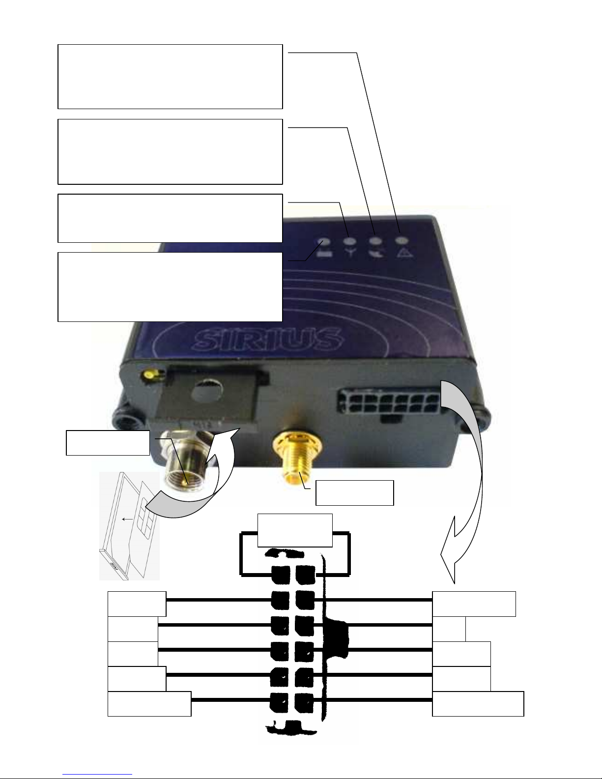
red
purple
Red/white
green
brown white
Black/yellow
yellow
orange
black
feeding +12V Ground
beeper alarm +
blocking
15
LED DALLAS
alarm -
bypass
DALLAS
Wire jumper of
backup
ACU
Green LED power supply
lighting – unit is ON, feeding is > 8V
flashing – unit is ON, feeding is < 8V
not lighting – unit is OFF
Green
LED GSM
Lighting of flashing – GSM modul
operation
Green
LED G
PS
lighting – GPS is ON, position valid
flashing – GPS is ON, position invalid
not lighting – GPS is OFF
Red
LED
Alarm
It lights up when some alarm input is
activated. After fulfilment of inquiries
(SMS, calls) lights off.
GPS antenna
GSM antenna
Page 4
3
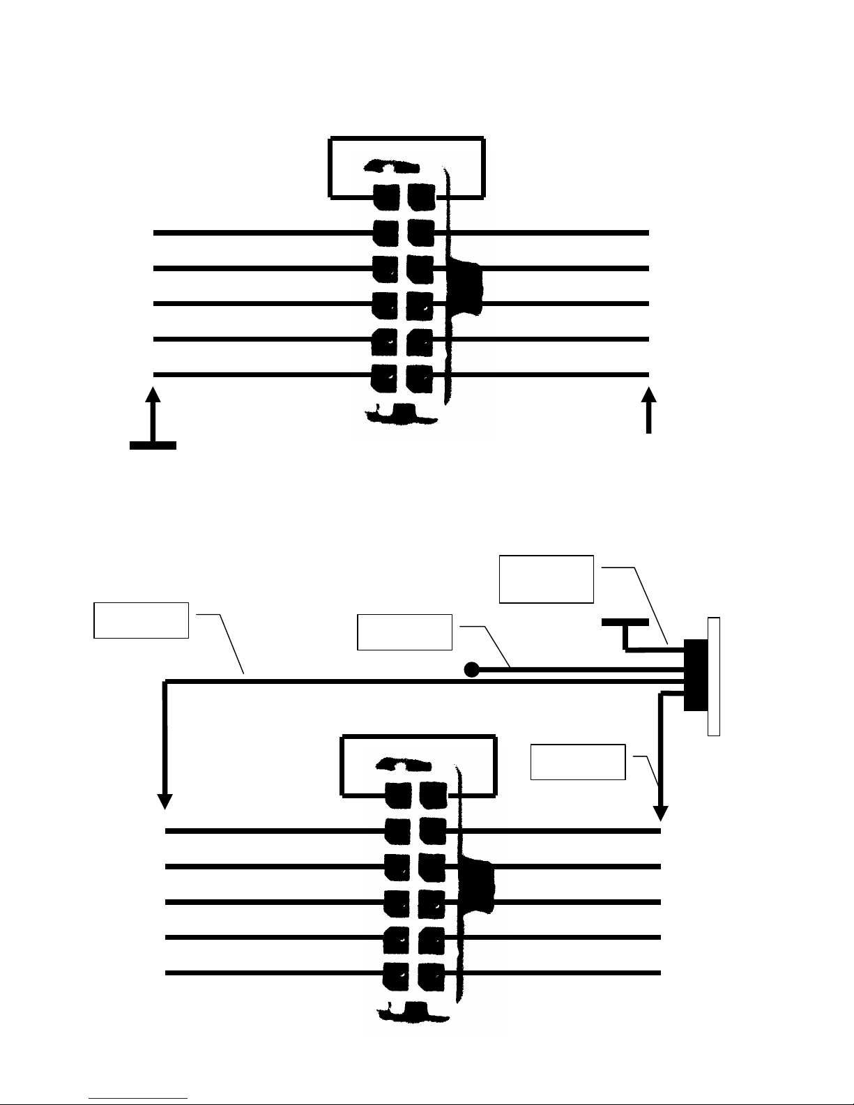
red
purple
Red/white
green
brown white
Yellow/black
yellow
orange
black
white
brown
green
yellow and
grey
red
purple
Red/white
green
brown white
yellow/black
yellow
orange
black
BASIC CONNECTION SCHEMATIC - MUST BE ALWAYS USED !
might be supplemented by other combination of connection
Connection of „Dallas“ (key)
+12V
Page 5

4
Connection of wireless card receiver ED 060 624
Alarm connection
red-brown
Black- brown
red
purple
Red/white
green
brown white
Yellow/black
yellow
orange
black
ED 060 624
+12V
Red- black
red
purple
Red / white
green
brown white
Yellow / black
yellow
orange
black
+12V
Alarm-
Alarm+
Page 6

5
Alarm connection „bypass”
Blocking connection
red
purple
Red/white
green
brown white
Yellow/black
yellow
orange
black
+12V
red
purple
Red/white
green
brown white
Yellow/black
yellow
orange
black
+12V
Page 7

6
Connection of sound signalling for Key
Unit operation start
1. Connect cables from connector up selected connection schematics
Do not connect the connector into the unit!
2. Insert SIM card.
3. Connect attached antenna GSM and GPS.
4. Double check correct polarity of power supply in connector as same as correct
cables connection (not short circuit, etc…)
5. Connect the connector into the unit – Green LED lights up with symbol
battery.
6. Wait for registration of the unit into GSM network (LED GSM is flashing).
7. The unit is ready for operation.
red
purple
Red / white
green
brown white
Yellow/black
yellow
orange
black
Bell, beeper on12V
(with own tone)
+12V
Page 8

7
LED Signalling
symbol Light of LED functionality
¤¤¤¤¤¤¤¤¤¤
¤¤ƒƒƒ¤¤ƒƒƒ
ƒƒƒƒƒƒƒƒƒƒ
Connection of feeding from car - battery
> 8V
Connection of feeding from car - battery
< 8V
The unit is switched OFF (back up
ACU is discharged)
¤¤¤¤¤¤¤¤¤¤
¤ƒƒƒ¤ƒƒƒ¤ƒ
GSM operation (registration, SMS etc.)
Stand by
¤¤¤¤¤¤¤¤¤¤
¤¤ƒƒƒ¤¤ƒƒƒ
ƒƒƒƒƒƒƒƒƒƒ
GPS is ON, position valid
GPS is ON, position invalid
GPS is OFF
¤¤¤¤¤¤¤¤¤¤
Activation of some services (power
supply disconnection, ALARM etc.)
¤ƒ¤ƒƒƒ¤ƒ¤ƒ
Start of unit (cca 1 minute)
¤ƒƒ¤ƒƒ¤ƒƒ¤
Activated – feeding from car - battery
¤ƒƒƒƒƒ¤ƒƒƒ
Activated – feeding from Back up
ƒ¤¤¤¤¤ƒƒƒƒ
(5s light) – code reception from key
ƒƒƒƒƒƒƒƒƒƒ
Ignition is ON (correct start)
ƒ¤ƒ¤ƒ¤ƒ¤ƒ¤
Ignition is OFF (correct start)
Sound signalling
____
- reading of attached key ____| |________________________________________
__ __ __ __ __ _ _ _ _ _
- record of key to SIM ____| |__| |__| |__| |__| |_| |_| |_| |_| |_| |_
__ __ __ __ __ __
- incorrect start ____| |__| |__| |__| |__| |__| |____________
__ _ _ _
- ignition switch off ____| |__| |_| |_| |_____________________________
Page 9

8
Telephone numbers saved on the SIM card
Name Example of number function
ADMIN +420123456789
Highest priority. It can SMS „CAR,ON“ and
„CAR,OF“ deactivate and activate unit. It
can sends also further SMS.
ALARMS +420987654321
To this number is sends SMS
'ALARM(AKU) + Credit' + position after
activation signal Alarm or feeding
interruption (Aku),
To this number is send SMS 'Incorrect start
!' (start without key deactivation)
To this number are also sends messages
from operator (credit status)
It can sends SMS except CAR
ALARMx
(x = 1..8)
+420123000001 (ALARM1)
+420123000032 (ALARM2)
+420123000111 (ALARM3)
+420012300012 (ALARM5)
+420123004567 (ALARM6)
It is dialling progresively after activation
alarm signal until interruption of line
(1,2,3,5), Progressive dialling is also ended
by pick up at called part (in handset you
hear interruption tone).
From those numbers can be sends system
SMS
OPER 4603 (T-Mobile)
number, from which are received SMS of
operator (credit status)
CRED
*101# (T-Mobile)
*104*# (Eurotel)
Code to identify credit status
ALTIM 05*10*02*35
Remote settings unit parametres:
Number is in format 'tt*bb*pp*uu', when:
'tt'.. 01 - 99 [decimal sec.] – pulse duration time at
input for alarm sensor (default 03 = 300 msec)
'bb'.. 01 - 99 [decimal sec.] – current duration time
for byppas alarm activation (default 30 = 3 sec)
'pp'.. 01 - 99 [min] – time between position reading
(default 01 min)
'uu'.. 35 - 39 [decimal volt] - min. voltage value of
back up ACU (default 36 = 3,6 V) – when voltage
is lower the unit is automatically switch OFF
KEY 1
'1' ... registration of attached keys„DALLAS“
(until ignition start – by this is automatically
rewritten to 0)
'0'...unlocking by attach of registrated key
„DALLAS“
Page 10

9
Table of SMS commands
identif. par. command body example description SMS reply Note
ALARM 1 to 8 , phone number )1 ALARM1,+42060212311 adding or change of phone number at positioni par. "OK"
ALARM 1 to 8 , ALARM2, erasing phone number on position par "OK"
ADMIN phone number )1 ADMIN,+42060212311 adding or change of phone number ADMIN "OK"
ADMIN erasing phone number ADMIN "OK"
#1111#POLOHA #1111#POLOHA request for identification of position position
PERMIT,DDMM,ddm , DDMM,ddmm PERMIT,3105,0206 permission for data access for 1 hour to memory of recorde
d position . For transmission will be selected period betwee
n dates DDMM and ddmm
"OK"
CAR , OF CAR,OF deactivation of unit ( unit react then for SMS "STAT" and "
CAR,ON" only from ADMIN number
"OK" ADMIN only
CAR , ON CAR,ON unit activation "OK" ADMIN only
BLOCK , ON BLOCK,ON closing of output for blocking (switch off ignition)
for closing must be valid position reading and speed under
15 km/h
"OK"
BLOCK , OF BLOCK,OF unblocking "OK"
RST RST unit restart "OK"
STAT STAT identification of unit status
programm version
ABCDE
Backup=x.xxV
Battery=yy.yV
Mode act
Block on (Block of)
credit
A=blok (1 ON)
B=key (1 od.)
C=alarm (1 on)
D=GPS (0 -off)
E=ignition
ALTIM , tt*bb*pp*uu 05*10*02*35 Remote setting of unit parametres "OK"
parametres in
previous table
CAL ,
ATD603123456; CAL,ATD603123456;
unit generate a call to set number immediatelly after receivi
ng )2
"OK" - call established
"NO CARRIER" - unreachable
"BUSY" - busy
CAL , ATH CAL,ATH zaøízení ukonèí probíhající hovor
CAL , AT+CPAS CAL,AT+CPAS identification of unit status
"+CPAS: 0" - stand by
"+CPAS: 3" - incoming call
"+CPAS: 4" - current beying call
CAL , AT+CSQ CAL,AT+CSQ identification of signal strength
"+CSQ: 17,99" - first number befor
e comma is signal strength(max 32
), min. value for calling is cca 17
CAL , AT+CPBR=par. CAL,AT+CPBR=1 identification of phone number on the SIM at certain positio
n par.
+CPBR: 1,"+420602123111",14
5,"ALARM1"
CAL , AT+CCLK=? CAL,AT+CCLK=? clock status in unit
+CCLK:“00/01/01,01:17:36” )
3
because clocks are set to 0 when u
nit is switch off , running since 1.1.
00. It always shows operation time
since last switch off ( short fails are
not registrated)
Page 11

TELSYCO s.r.o.
Prostřední 627/14
141 00 Praha 4
e-mail:
info
@telsyco.com
tel./fax: +420 241 765 832
ww
w.telsyco.com
www.telsyco.c
om
Registered company address:
TELSYCO, s.r.o.
Prostřední 627/14
141 00 Praha 4
Czech Republic
VAT: CZ28548302
Company is registered in the Commercial Register administered by the Municipal
Court in Prague, Section C, Record 149478
TELSYCO s.r.o.
Office:
Kyjovská 1983/1
142 00 Praha 4
Czech Republic
E-mail: info@telsyco.com
Tel/Fax: +420 241 765 832
 Loading...