

Telsyco MiniGate A Installation Manual
e-mail:
info
@telsyco.com
tel./fax: +420 241 765 832
www.telsyco.com
TELSYCO s.r.o.
Prostřední 627/14
141 00 Praha 4
G S M G A T E
MiniGate A
MiniGate AMiniGate A
MiniGate A
Installation guide V 1.0

- -
1
Basic features:
Mini Gate A is dual band GSM Gate based on Siemens GSM
module TC 35 ( eventually MC 55) equipped by a lot of
adjustable features increased comfort of service. It has been
designed for GSM network 900 MHz as same as 1800 MHz.
• Polarity reversal of telephone line allows exact detection of
start and end of call.
• CLIP support all ordinary protocols and allows send not
only incoming call number but also name ( when is saved
in phonebook).
• Call billing allows control exact call duration due tax pulses
12/16 kHz (1. pulse when outgoing call is picked up).
• Beeps in minute period into the call allows easy
identification of GSM call.
• Integrated USB port with PC software allows you easy
configuration as same as sending and receiving SMS
messages ( via SMS mail sw)* or data transmission.
*
option
Thanks of many Mini Gate features you can satisfy very wide
group of customers. By setting of permitted numbers to
memory of Mini Gate you can restrict unrequested calls (to
public numbers).As same as you can set Mini Gate to provides
incoming calls only.
- -
2
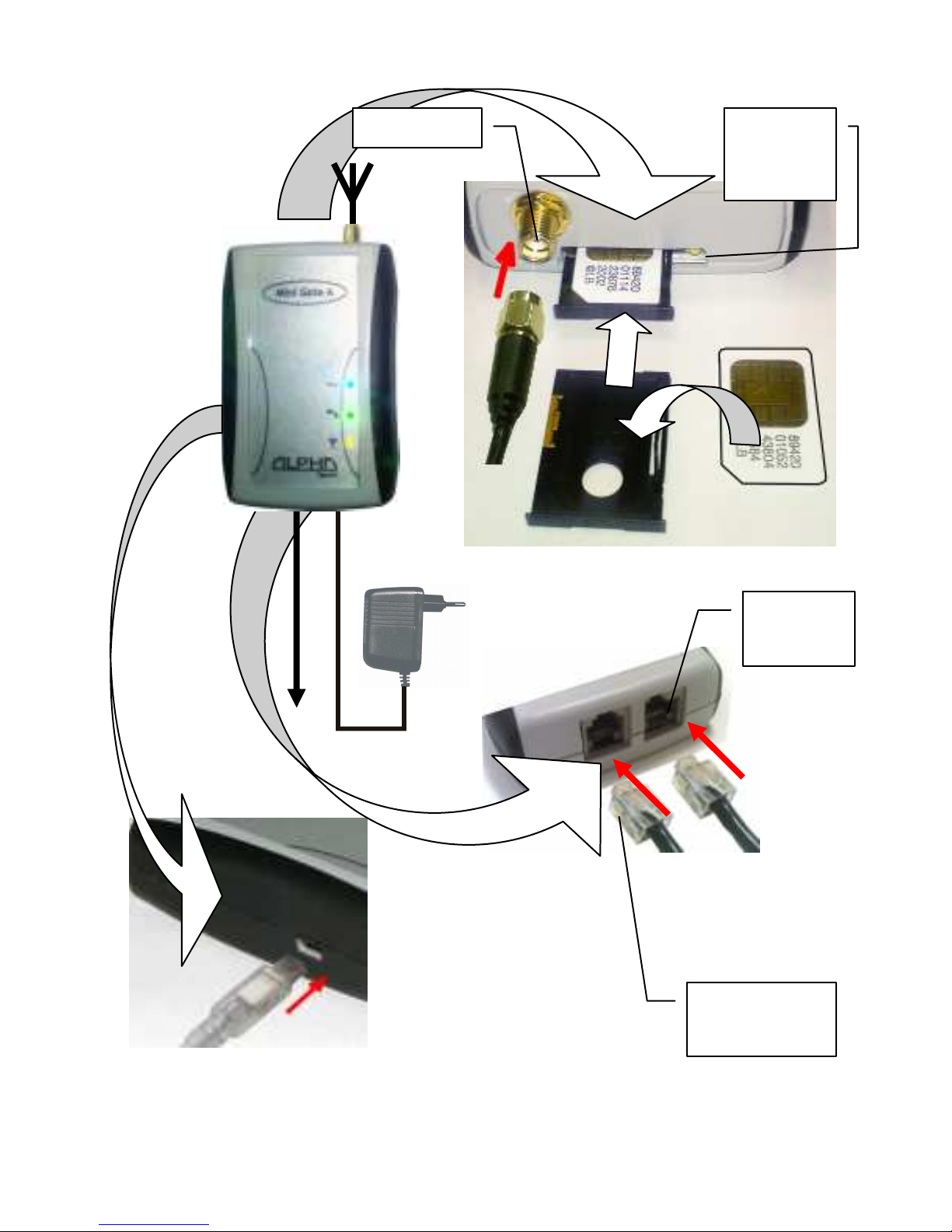
INSTALLATION
Power
supply
telephone
line
USB
(Mini USB
cable)
Yellow
button
anntena

- -
3
By pressing of yellow button release the SIM card holder.
Insert the SIM card and replace the SIM card holder. Before
inserting the SIM card we recommend checking at
various mobile phone state of the SIM card (logging with
or without PIN, PIN, etc.) and set logging without PIN.
When you want logging with PIN you have to
preprogrammed this PIN and set logging with PIN (via
table of programming).Without this setting the Gate wont
work. DO NOT FORGET ANTENNA CONNECTION! The
available place for installation select up following point of view:
1. distance from PBX – possibility of GSM interferences to
other PBX lines as same as lenght of line from Gate to
PBX (max. 200m)
2. main 230 V for power supply of Gate
3. Quality of GSM signal at the installation place of GSM
Gate
Quality of GSM signal
The sound quality depends on BTS setting where you are
connected by the Gate. To find best place for antenna
mounting you can use either mobile phone or feature 29 (table
of programming). The suitable signal power is 3 scales of
mobile graduation.
To check and find best position from GSM signal point of view
you can use also GG SET ( configuration sw). More in manual
for GG SET.

- -
4
Connection of antenna
When you connect magnetic antenna keep on mounting at
bigger iron subject. This subject makes „against-weight“ at its
depends the power of radiated signal
When you inserted SIM card as same as all cables are
connected (do not forget that Blue gate is connected on
external line not on extension) connect device to main
230V. The blue LED of „power supply„ is light up within 10 sec.
After a while will flash a few times unregularly yellow LED
(GSM network registration). Tle CPU then waiting for
communication to GSM module ( via LED table –
communication off). After cca 30 seconds the yellow LED start
flashing up GSM signal strength ( via LED table).When pick up
connected analogue phone or call to Mini Gate from PBX the
LED of analogue line lights up (green LED). In the phone is
hearing dial tone of Mini Gate. It is ready to use.
The most often problems during Blue Gate
compact installation:
All LED is not lighting.Problem in power supply. Check
connection to main 230V as same as connection of
adapter to Mini Gate.
The LED “power supply” lights. When you make
connection to Gate green LED is ON and in handset
you hear busy tone. Yellow LED flashing in period
„GSM modul doesnt communicate with CPU“. During
work with USB could be programmed fix communication
rate for GSM modul. Use USB to programm rate on
„autobauding“.

- -
5
The yellow LED flashing in period „PIN unreadable“.
After calling to Mini gate you get busy tone. The SIM
card requires PIN, which is not preprogrammed or is
preprogrammed wrongly.
The LED „communication to GSM„ is flash shortly one
for 2 sec. After calling to Mini Gate you are hearing busy
tone. Mini Gate is not log into GSM network – bad
signal.
The yellow LED „communication to GSM„ is flashing up
signal strength“. After calling to Mini gate is not light up
green LED is not light up and in analogue phone is
quiet. It interrupted conduction of analogue line or so
much big resistance in current loop (for example:(
longer cabel between PBX and Mini Gate).
Tle yellow LED „communication to GSM„ is flashing up
signal strength“ as same as green LED lights up. Tle
PBX hold „pick up“ line of GSM Gate. By incoming call
you can remove this issue. In other cases check PBX
manual.
The Mini Gate works but call is disturbed by
interference. Incorrect position of antenna against
telephone line. Change antenna position.
Note:.
Default you make by parametr 99 in programming mode (via
programming table at page 11).
Alle LEDs flashing as same as tone types are mentioned in
tables at the end of manual.
 Loading...