

Telsyco IPDP – 00, IPDP – 00C, IPNC1 - mod, IPNC2 - mod, IPNC4 - mod Installation And Operating Instructions Manual
...
TELSYCO s.r.o.
Prostřední 627/14
141 00 Praha 4
e-mail:
info
@telsyco.com
tel./fax: +420 241 765 832
www.telsyco.com
Door Phone IPDP
IPDP – 00
IPDP – 00C
IPNC1 - mod
IPNC2 - mod
IPNC4 - mod
NC - mod4
NM - mod4
IPDP-K
Installation and Operating Instructions

Welcome
We congratulate you on purchase of “DoorPhone VoIP” (VoIP = Voice over
IP), which is the improved version of successful “New DoorPhone” (NUDV).
This DoorPhone VoIP will widely manage to satisfy your needs of
communication with persons at the building front door or your company entry,
or family house doorway. The universality lies in possibility to connect this
guard to an Ethernet network or VoIP exchange or directly to SIP server
through internet conection.
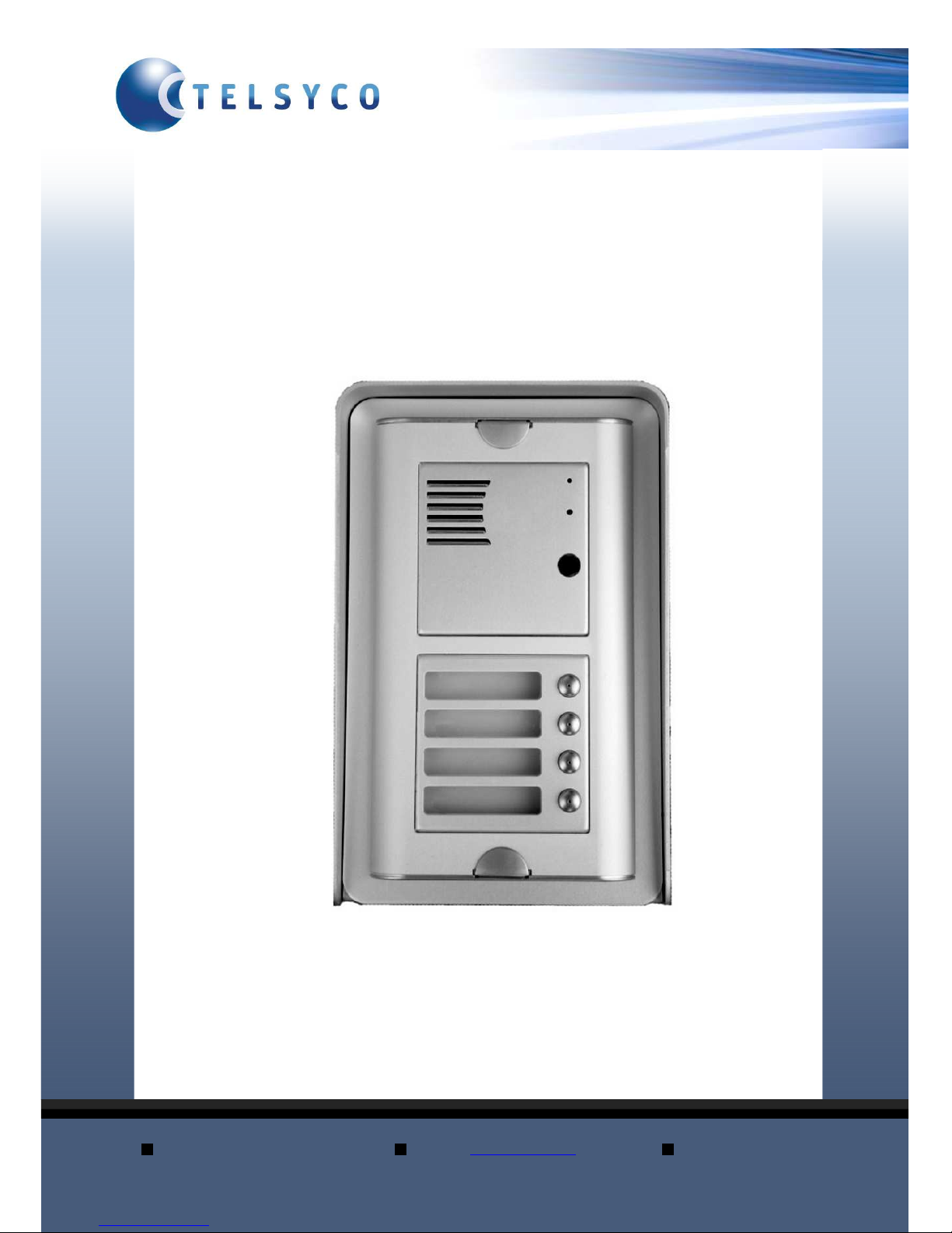
The basic DoorPhone VoIP module (IPDP-00) is supplied without button. The
next version of basic VoIP module (IPDP-00C) is with integrated colour
camera. The buttons modules are connected to basic module (IPDP-00 or
IPDP-00C) and they are manufactured with 1, 2 or 4 buttons with Ethernet
connection (IPNC1-mod, IPNC2-mod, IPNC4-mod). Further the whole system
allows to be enlarged by NC-mod4 and NM-mod4 modules up to 64 buttons
using the basic mechanical MK1...MK4 units. The whole assembly can be
completed with cover frame or rain-protective case for flash or surface
instalation.The last optional module is Keypad (IPDP-K).
The Doorphone is supplied from AC/DC powersupply 12V. The basic features
include the possibility to open up to two doors by means of connected electrical
locks (the first 10 buttons can be used for door code opening) and easier
programming by WEB sites from PC by network connection.

IPDP - installation and operating instructions
3
Table of Contents
DOORPHONE VOIP................................................................................................... 1
1
BASIC DESCRIPTION....................................................................................... 4
1.1
F
EATURES
...................................................................................................... 4
1.2
M
ODULE ASSEMBLY
...................................................................................... 5
1.3
M
ODULE FEATURES
....................................................................................... 6
1.3.1 IPDP Basic Module .................................................................................. 6
1.3.2 Extending Module IPNCx-mod, NC-mod4 and NM-mod4........................ 9
1.3.3 IPDP-K Keyboard Module .................................................................... 10
1.4
I
NSTALLATION OF DOORPHONE VOIP ASSEMBLY
....................................... 11
1.4.1 Installation on Plaster............................................................................. 11
1.4.2 Flush-Mounted Installation .................................................................... 11
1.5
C
HANGE OF NAMEPLATES
............................................................................ 11
1.6
F
OCUS CAMERA AND DESCRIPTION OF FRONT PANEL
................................... 13
2
DOORPHONE VOIP OPERATION ............................................................... 14
2.1
S
IGNALING OVERVIEW
................................................................................. 14
2.2
V
ISITOR AT DOOR
........................................................................................ 14
2.2.1 DoorPhone without Keyboard ................................................................ 14
2.2.2 DoorPhone with Keyboard..................................................................... 15
2.3
P
ERSON INSIDE OBJECT
............................................................................... 16
2.3.1 Outgoing Call ......................................................................................... 16
2.3.2 Incoming Call ......................................................................................... 16
3
PROGRAMMING OF PARAMETERS.......................................................... 17
3.1
B
ASIC VOIP SETTINGS
................................................................................. 17
3.1.1 Choosing a mode and login .................................................................... 17
3.1.2 Language option ..................................................................................... 18
3.1.3 Network settings...................................................................................... 18
3.1.4 Peer to peer or SIP server connection.................................................... 20
3.1.5 Audio codec setting................................................................................. 20
3.1.6 Setting video............................................................................................ 21
3.1.7 Service settings ....................................................................................... 22
3.2
S
ETTING DOORPHONE PARAMETERS
............................................................ 23
3.2.1 Basic Parameters.................................................................................... 23
3.2.2 All about relays....................................................................................... 24
3.2.3 Time Parameters..................................................................................... 26
3.2.4 Direct Dialing – Memories ..................................................................... 27
4
TECHNICAL PARAMETERS......................................................................... 28
4.1
E
LECTRICAL PARAMETERS
.......................................................................... 28
4.2
M
ECHANICAL DIMENSIONS
.......................................................................... 28

IPDP - installation and operating instructions
4
1 Basic Description
1.1 Features
Modular system allows to connect 4 to 64 buttons
Voice communication is supplied only from telephone line
Two 16digit numbers (IP adress) with each button
Day/night switching
Possibility of the call extension by * or # choice
Possible to connect two independent locks for door opening
Possible use of 5 switch modes (e.g. camera, lighting, gradual
opening)
Two codes for hanging up the guard from telephone
Two codes for door opening from telephone
Six code locks (password from buttons at the door)
Possibility to connect a numerical keyboard this way that the guard
can include 4 – 18 standard buttons
Integrated heating of printed circuit
Permanent lighting through visiting cards
Included color camera
Ethernet – 10/100Mb with standard 10BaseT a 100BaseTx
Web server for remote configuration – BOA
Power supply 12V AC/DC, 500mA
Operating system – Linux 2.6
USB for connection camera – USB guest 1.1, software GSPCA
software for video transmission to the browsers in PC – W3CAM(JPEG, RTSP Streem)
SIP connection P2P or PBX network system
WEB – firmware upgradeable
WEB – interface for control and setup parameter
IPDP - installation and operating instructions
5
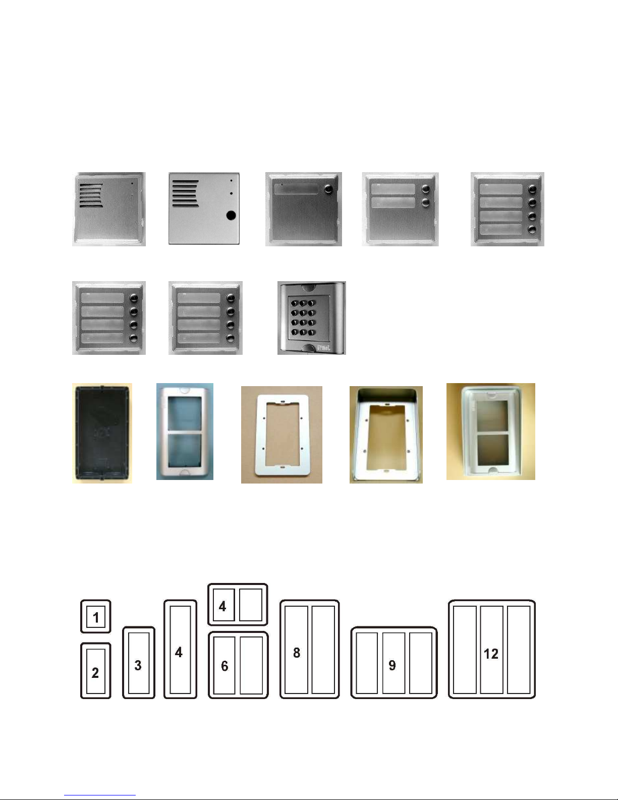
1.2 Module Assembly
The IPDP structural elements are the basic modules with color camera
IPDP-00C or without camera IPDP-00 and extending button modules
IPNC1-mod with one button, IPNC2-mod with two buttons, IPNC4-mod,
NC-mod4 and NM-mod4 with four buttons. Further it is possible to provide the
assembly with numerical keyboard. The complete assembly consists similarly
to IPDP system of max. 4 modules in column and max. 3 columns side by side.
IPDP-00 IPDP-00C IPNC1-mod IPNC2-mod IPNC4-mod
NC-mod4 NM-mod4 IPDP-K
MK-2 Fixing Flanging frame2 Canopy2 KPD2-rain
frame 2 (flush -mounted) protective cover (on plaster)
(flush-mounted)
By flush-mounted assembly the MK-1 to MK-4 boxes are used as well as with
UDV system.
Examples of frame configuration
IPDP - installation and operating instructions
6
1.3 Module Features
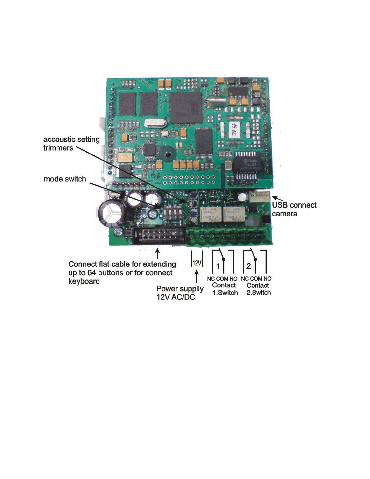
1.3.1 IPDP Basic Module
The IPDP basic module assembling from modulus IP and
motherboard. Positioning setting elements and connectors is on picture 1.
Picture 1 Basic module - motherboard
The “14 pin black conector” serves the connection of extending modules by
means of flat cable.
The “USB” serves the connection internal color camera
IPDP - installation and operating instructions
7
For IPDP is necessary used the AC voltage of min. 10Vst - max. 15Vst or DC
voltage of min. 12Vss to max. 18Vss must be energized to “12V” terminal. This
source loading depends on number of modules, since it simultaneously serves
feeding of lighting through visiting cards – at max. number of connected
modules the demand will not exceed 300mA. This source can be also used for
feeding of lock(s), and then it is necessary to consider the electrical lock
demand. In practice the alternating feeder 12V/1A mostly meets these
demands.
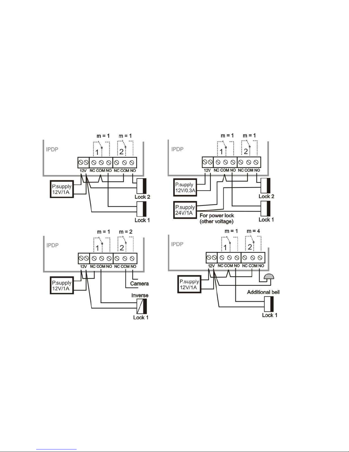
The connection of relay contact terminals is shown on fig. 1. The “NO”
designation means an idle-disconnected contact, “COM” means a pin contact
(middle) and “NC” means an idle-connected contact. The contacts of both
switches are galvanically isolated each other and from other guard circuits. The
variants of connection are shown on picture. 2.
Picture 2 Examples of relays connections
IPDP - installation and operating instructions
8
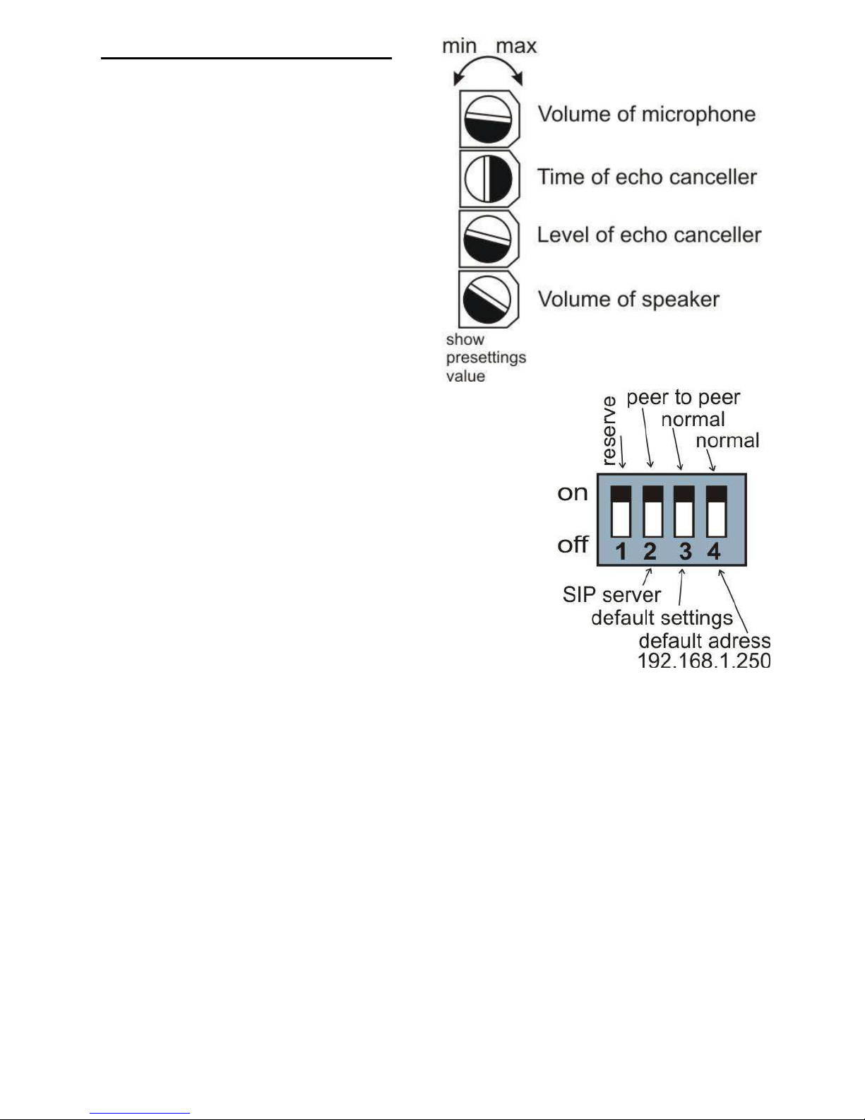
Setting voice communication –
position trimmers are presetting from
manufacture and in majority case
agree with, therefore changes setting
altering only in necessary case. Basic
position of trimmers, sense of rotation
and meaning trimmers are illustration
on picture 3.
Picture 3 Setting of trimmers
DIP switch setting basic operation and default
setting. See on picture 4.
Picture 4 DIP switch settings
IPDP - installation and operating instructions
9
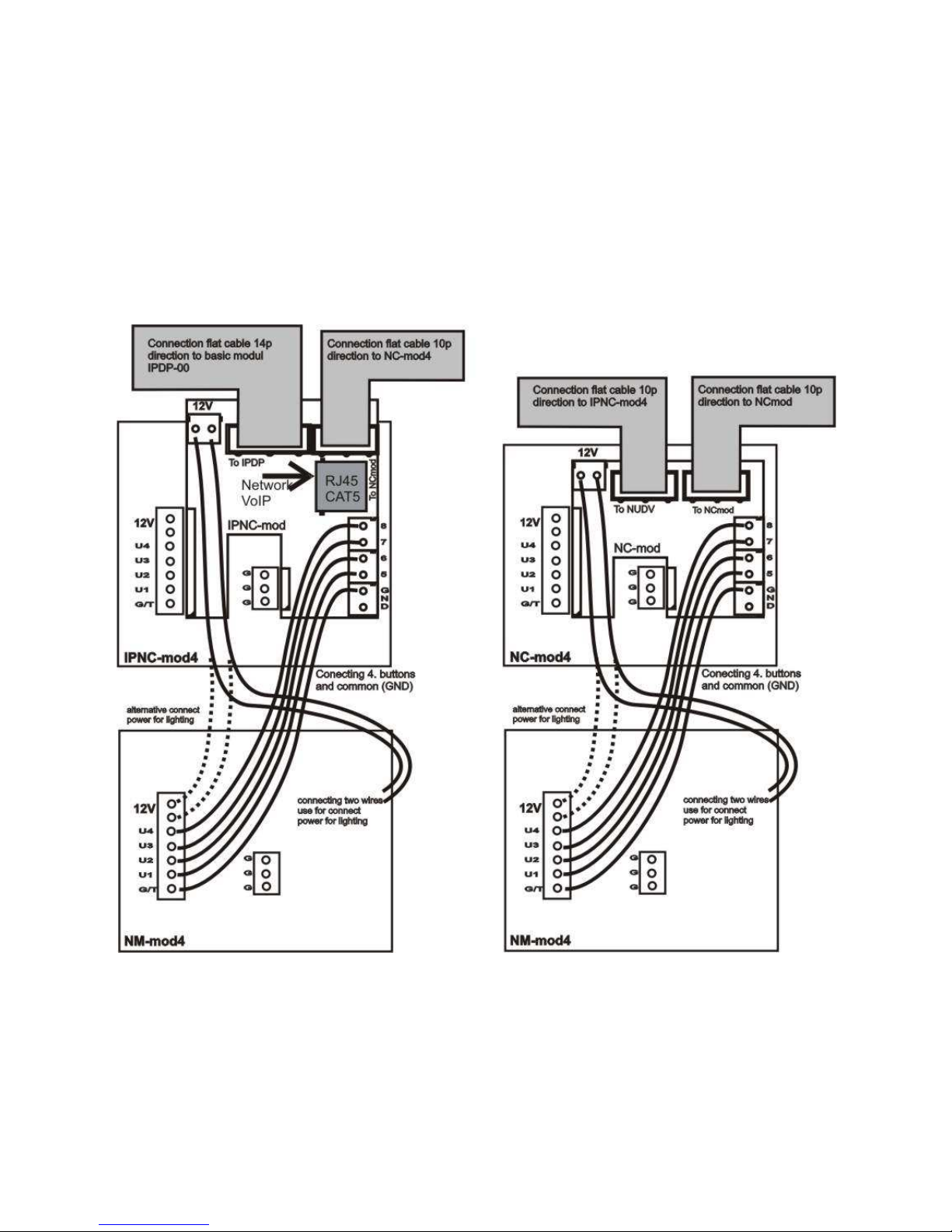
1.3.2 Extending Module IPNCx-mod, NC-mod4 and NM-mod4
This module is supplied in three designs. The IPNCx-mod module
(picture 6) has four buttons and includes the electronics to be connected to the
basic module. The NC-mod4 module has four buttons and includes the
electronics to be connected to the IPNCx-mod or to previous NC-mod4 module.
This module is only connected by flat cable – buttons and lighting through is
already interconnected. The terminals for connection of other four buttons and
current supply of lighting are further placed on module (on following NM-mod4).
The NM-mod4 module is always connected to previous IPNCx-mod or
NC-mod4. The connection is not prepared and should be done by conductors –
see on picture 5.
Picture 5 Connection of (IP)NC-mod4 and NM-mod4
 Loading...