

Page 1

e-mail:
info
@telsyco.com
www.telsyco.com
TELSYCO s.r.o.
GSM remote control
GSM
GSM key
GSM GSM
key
keykey
Prostřední 627/14
141 00 Praha 4 - CZ
User manual v 4.0
tel./fax: +420 241 765 832
Page 2

Basic technical parametres:
Power supply 9 to 15V ss, 500mA
GSM network 900/1800MHz
dimension: 145 x 75 x 30 mm
Features :
o Power supply from distribution net 12V or alternative from
main power supply (12V adapter). Also can be used
backup battery 12V with charging adapter.
o 2 inputs for switching contacts (alarm output, sensors etc.)
(5V)
o when is short circuit at input preprogrammed SMS is sent
to preprogrammed number (for each input own text SMS
as same as number)
o when is short circuit at input progressive ringing up 8
preprogrammed numbers (ALARM1 to ALARM8)
o 2 galvanically separated (switching contacts 230V/ 5A)
o 2 switching contacts control by ringing only from authorised
numbers (contact closed for preprogrammed fix time )
o The size of authorised numbers is limited by SIM card
capacity (250). The numbers can be saved under different
names
o Both outputs control by SMS from numbers authorised in
II. level (ALARM). It is possible remotely control closing,
disconnection, closing for 1-99 minutes
o Setting of all parametres (authorised numbers, unit time,
competence etc.) a s same as complete control of the unit
(for example: remote dialling different number from
preprogrammed) by SMS from authorised numbers in level
III. (ADMIN)
o Ckecking of credit level. Sending of SMS coming from
operator to preprogrammed number.
o Setting of all parametres via PC through RS 232 port. All
parametres can be programmed directly on SIM by mobile
phone or remotely by SMS
o Systém interface for optional devices
1
Page 3
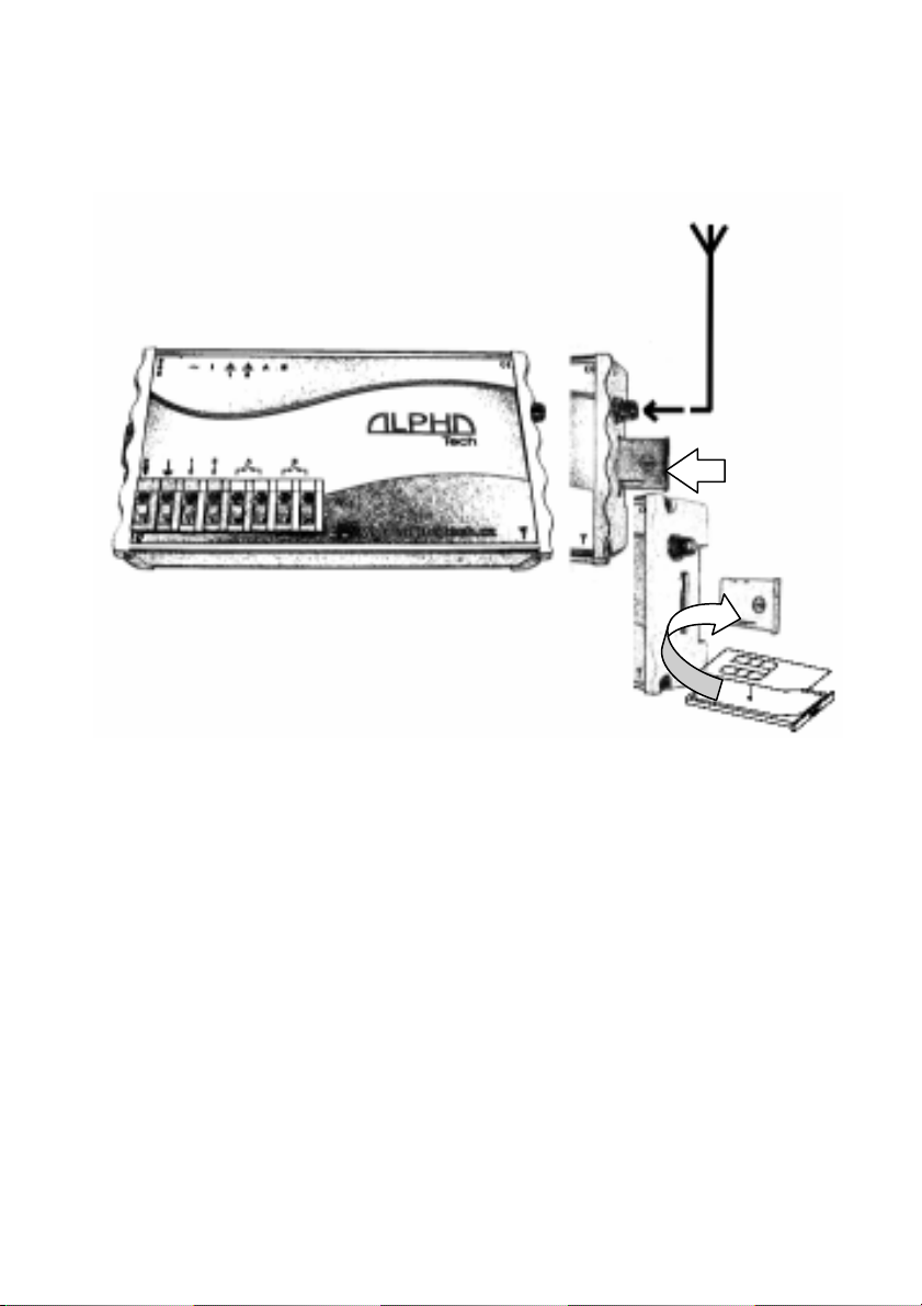
Installation
The unit may be installed on DIN ribbon, screw on the wall or
put to the shelf. The unit is not designed for installation in high
humidity environment. If you want install it in external
environment you have to fix it into waterproof box.
SIM card setting
Insert SIM card to various mobile phone
Where you can programm neccessary parametres.
Much more comfortable way is insert it into unit and
parametres programm via PC through attached programming
cable. For PC setting use configuration software on CD which
is attached to the unit.
CAUTION! On the SIM card must be saved at least 1 phone
number when you want control relay by ringing. Further
more at least 1 ADMIN phone number, when you want
remote control of the unit. At least ALARM1 phone
number, when you want receive call after input activation.
THE NUMBERS MUST BE IN INTERNATIONAL FORMAT!
Inserting of SIM card into unit
Pull out SIM card holder by pressing of yellow button on right
side of the unit. The SIM card put to holder and replace it.
2
Page 4
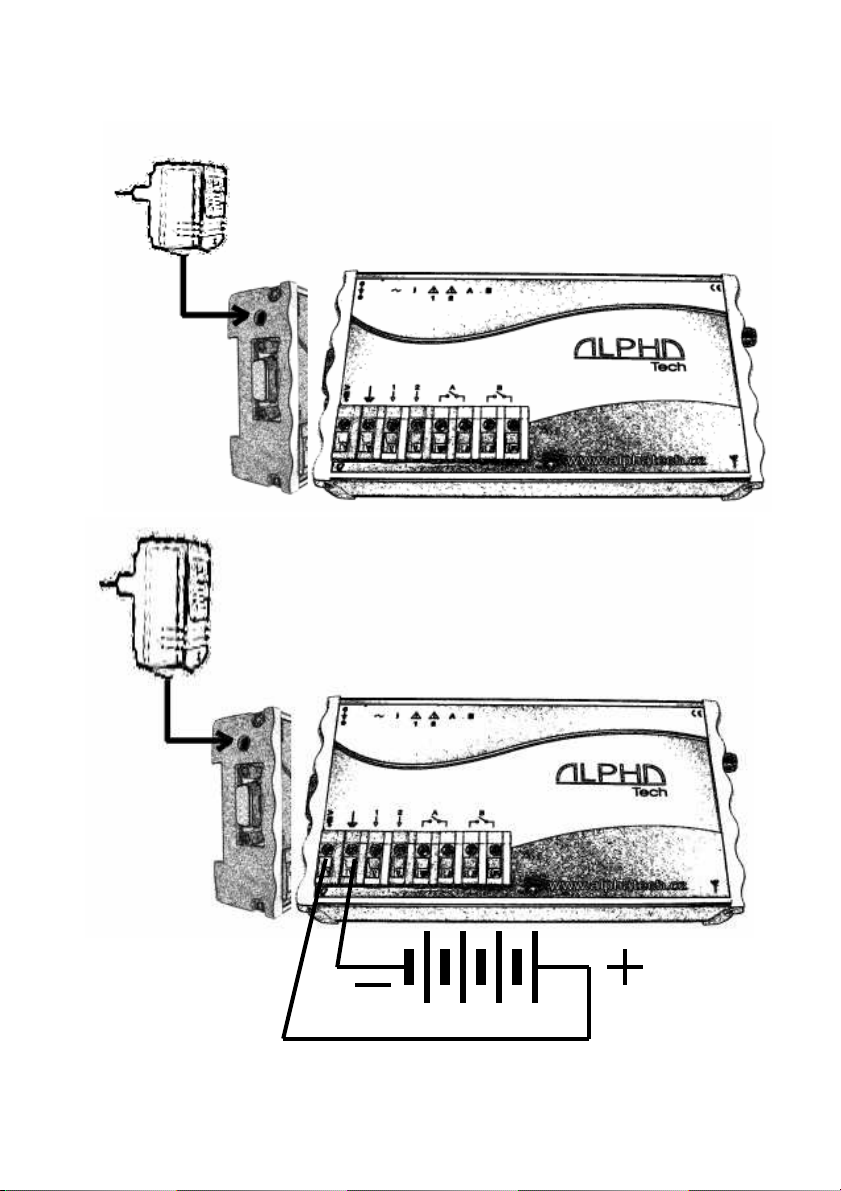
Schematics of feeding with delivered power supply
Schematics of feeding with charging
power supply and backup 12V ACU
3
Page 5
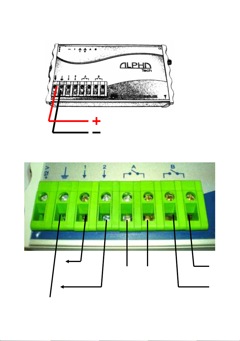
Schematics of feeding from 12V distribution
12V distr, consumption max 500mA
Schematics of Inputs/Outputs
Input 1
(against GND)
Output A
Output B
Input 2
(against GND)
4
Page 6
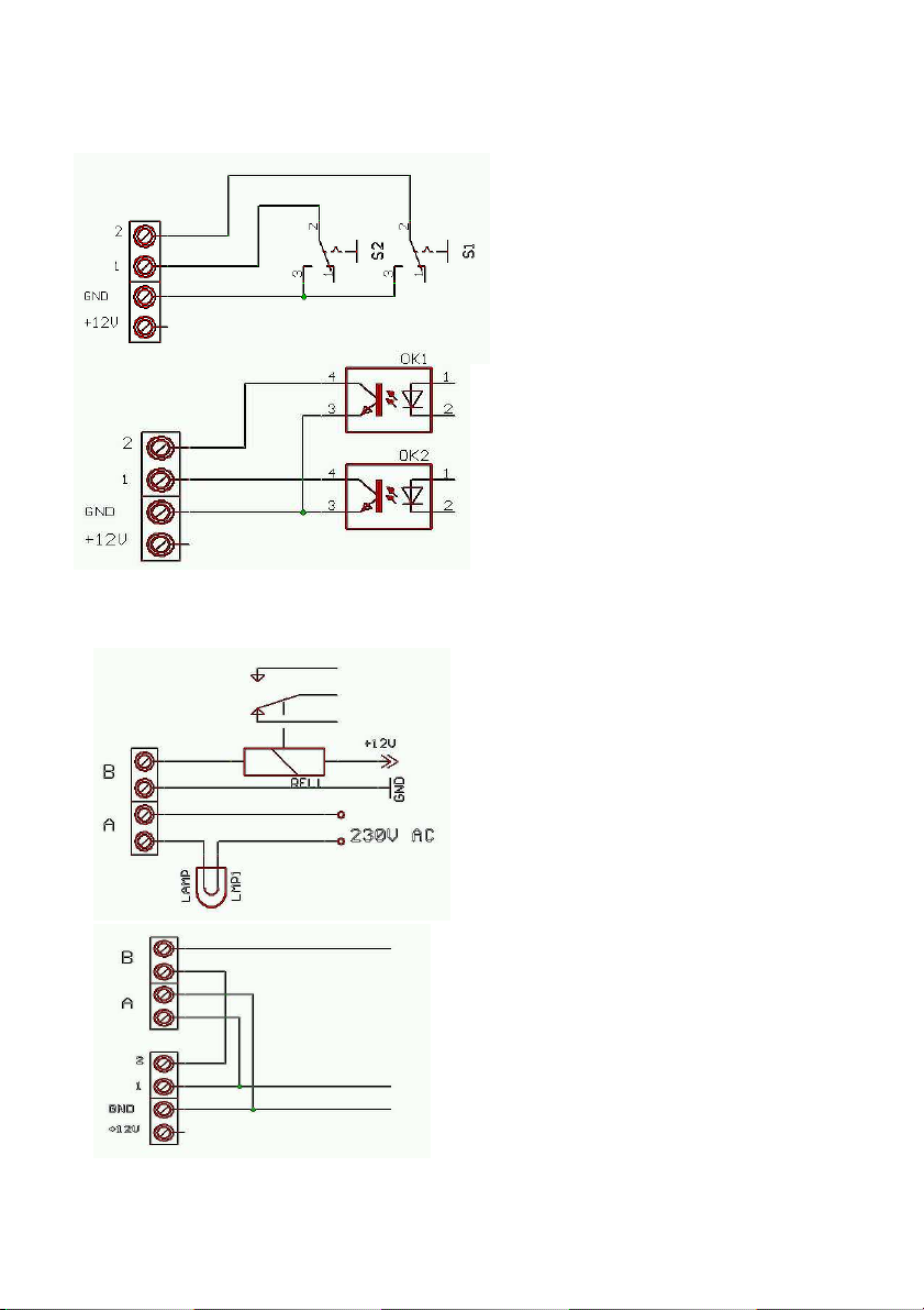
Inputs connection examples:
Outputs connection examples:
Selftest Input 1 (due relay A) –
possibility activate Alarm
remotely, Blocking Input 2 (due
relay B) – Remote control of
alarm circuit = Guarding for
limited time
Connection with relay
contacts, switches,
magnetic contact switchers
etc.
Connection of galvanically
isolated switch with
optotransistor
High power relay (clamper)
connection , lightbulb
connection (heating, engine
etc.).
5
Page 7

Indication LED
Blue LED
Lighting – feeding from power supply
Flashing – feeding from Backup ACU
Yellow LED
Short flashing – GSM network search
Slow flashing – GSM network ready
Fast flashing – SIM card error
Red LED
Lighting during input
activation
Green LED
Flashing – output permanently closed
Lighting – output closed for mm minutes
6
Page 8

Names and numbers to save on SIM card
Name functionality
various By ringing activate output A (closing time set in RTIME)
ALARM1
to
ALARM8
ADMIN1
to
ADMIN8
ARMSMS1
to
ARMSMS8
CRED - code to assure credit level
OPER - GSM operator number where from coming inform SMS
RTIME - Time of closing output A after ringing (1-99sec), default
- By ringing activate output A (closing time set in RTIME)
- By SMS activate output A and B
- By SMS control (status, version, IMEI, credit)
- During failure on input 1(2) is send SMS from position 2(3)
and progressively ring to line of ALARMx numbers (until line
interruption)
- when power supply is disconnected for 30 sec. and more
the SMS in format 'ACCU,credit’ is sent to ALARM8 number
- when power supply is working again longer than 30 sec. the
SMS in format 'POWER ON,credit' is sent to ALARM8
number
- By ringing activate output A (closing time set in RTIME)
- By SMS activate output A and B
- By SMS control (status, version, IMEI, credit)
- By SMS edit numbers and names saved on SIM card
- By SMS control further functions (AT commands)
Extendig of phone numbers where are send SMS messages
from Input 1 and 2. When ARMSMS is used and SMS are
not preprogrammed, the sends SMS „INPUT1 (2)“.
ARMSMSs phone numbers „MUS NOT“ be the same as
ALARMs or ADMINs numbers !!!
(*101# ... for T-MOBILE, *104*# ... for O2)
(expiration time etc..). The SMS is resent to ALARM8
3sec
The name and numbers may be saved to SIM card phone
book by mobile phone or by PC via configuration sw. The
names ALARMx, ADMINx, ARMSMSx, CRED, OPER and
RTIME must be written by BIG characters. Between name
ALARM (ADMIN, ARMSMS) and number ( ALARM1,2…)
must not be a space. The ALARM numbers must have
voice mail switch OFF! When ALARM number is busy or
unreachable the call is picked up by voice mail and further
numbers are not ringed!
7
Page 9

Command SMS – SMS with other content are refused
Command ( SMS) Function response
ADMINx,+420cc...c Save or rewrite ADMINx
number
ADMINx, Erase ADMINx number 'OK,credit'
ALARMx,+420cc...c Save or rewrite ALARMx
number
ALARMx, Erase ALARMx number 'OK,credit'
ARMSMSx,+420c.c Save or rewrite ARMSMSx
number
ARMSMSx, Erase ARMSMSx number 'OK,credit'
CRED,x..xx Save or rewrite CRED number 'OK,credit'
CRED, Erase CRED number 'OK,credit'
OPER,x..xx Save or rewrite OPER number 'OK,credit'
OPER, Erase OPER number 'OK,credit'
RTIME,ss Time closing of output A during
ringing (ss=01..99 sec)
SMSx,x..x,text Save SMS on position x (1-6) 'OK,credit'
SMSx, Erase SMS on position x 'OK,credit'
NAME,+420cc....c Save phone number for NAME 'OK,credit'
NAME, Erase all numbers with NAME 'OK,credit'
NAME,+420cc....c-
DEL
CAL,AT+CSQ Valuation of GSM signal
SMS is possible send from ADMIN numbers only!
CAL,AT+CPBR=x Detection of number saved on
STAT Status inquiry 'status,verze,i
REL1,ON Activate relay 1 (Output A) 'OK(REL1,ON)
REL1,OF Deactivate relay 2 (Output A) 'OK(REL1,OF),
REL1,ON,mm Activate relay 1 (Output A) for
REL2,ON Activate relay 2 (Output B) 'OK(REL1,ON)
REL2,OF Deactivate relay 2 (Output B) 'OK(REL1,OF),
Valid for ALARM numbers
Erase exact number with NAME
(may exist more times !)
strenght
position x
time mm, where mm=01..99
min
'OK,credit'
'OK,credit'
'OK,credit'
'OK,credit'
'OK,credit'
'+CSQ,17,99,
credit'(max 32)
'+CPBR:1,”+42
1012345678”,
145,”ADMIN1”
mei,credit' )*
,credit'
credit'
'OK(REL1,ON,
mm),credit'
,credit'
credit'
8
Page 10

REL2,ON,mm Activate relay 2 (Output B) for
time mm (mm=01..99 min)
'OK(REL1,ON,
mm),credit'
Note:
credit The level of remaining credit on prepaid cards.
x..xx telephone number
text text of SMS message
SMS1 SMS message sent when unit is switch ON
SMS2 SMS message sent during activation input 1
SMS3 SMS message sent during activation input 2
SMS4-6 back up for OEM messages
)* status – Inputs as same as outputs status in order
INPUT1, INPUT2, RELAY1, RELAY2.
INPUTx = 1 – stand by
0 – alarm status
RELAYx = 0 – switch off
1 – switch on permanently
2 – switch on for time 'mm'
verze – firmware version
imei – IMEI of integrated GSM modul
CAL, after command CAL you can put various AT command
of used GSM modul (for example: modul reset , time
setting etc...) . The commands should be used by
authorised person only! It may cause demage of
all unit!
Closing contacts by ringing
The relay outputs might be closed on 2 sec (or time RTIME) by
ringing from various number saved on SIM card (Even ALARM
and ADMIN). The output A is closed by direct ringing, Output B
by „diverted ringing“. To create „diverted ringing“ we have to
get next telephone number (called „X“) , on which we activate
permanent divert to number used in GSM Key. To close output
B we do not call number in GSM Key but number „X“ – follow
is managed by GSM Key and GSM operator.
9
Page 11

How you can get further phone number? The best is to
manage next SIM card on which you activate permanent
divert. However you have further options. The second number
on current SIM card ( data number, fax number, second
number – depends on GSM operator services and prices).
When you want control output B by SMS the second number is
not neccessary.
Example of real operation
At enter to your house you have connected output A to open
your gate. The output B is used for deactivation Alarm system
(Alarm systém OFF during time of relay closing). Input1
connected to alarm of your security systém and input 2 to
humidity (fire) sensor.
You will save to the unit (SIM card) your mobile number as
ADMIN1 and ALARM1. The mobile your wife save under
various name. Programm appropriate format of SMS for both
inputs (for example. “ALARM!” and “CAUTION high water
level!”) with number of your mobile pohone. To your as same
as wife mobile save number of the unit ( SIM) to speed dial.
Now you dont need 2x radio controller for Gate opening. You
are coming (or wife), give a ring to the unit, units detects your
CLIP and reject your call (it is for free) . The Gate is
openening.
You are working. Your mobile is ringing. You see Name of
your unit! SMS! ALARM! Mobile ringing again: neighbour –
“Your Alarm is screaming again!! Do something !!! Next call
coming – your wife, “Dear? I propably forgot to switch off the
alarm and I am not able to manage. I returned home for…..
and I am just leaving!” Your are quite. Select prepared SMS
“REL2,ON, add 60 (because you know „just leaving“ takes cca
45 minutes) and send to the unit. The unit response by SMS
“OK(REL2,ON,60) – command confirmation.
It should come new gardener Mr. Parker ( for example) to cuth
the grass and plant saplings etc.. You send from your mobile
10
Page 12

SMS: Parker,+420123456789. Since now Mr. Parker can
control your gate as well. After his job is ending you will erase
similiary his name from phonebook.
Obviously you have the same unit in company( you will not use
a few radio controllers??? When all you manage by your
mobile phone). It is evening. At home is celebration. You get a
call: “ We just arrived with material but store is closed. You
have to come and open it!
No, you dont!
Just give a ring to the unit from your mobile phone!
11
Page 13

PC programming by configuration sw.
Installation and uninstallation of software
2 files (file with end .exe and file with end .ini). From selected
language spot on CD copy to choosen ( or created) directory in
your PC. During first run programm creates all neccessary files
in this directory. When you copy file .exe only the english
language version will be created.
By erasing of this directory you uninstall all aplication.
PC connection tool
The operating unit ( switched ON) connect to PC via supply
USB cable (you have to install USB driver from attached CD)
or via seriál cable + special convertor ( see on picture).
.
Run the programm and select seriál port where unit is
connected
12
Page 14

Basic window of the programm
connection
Prepared blank phone book
Save and read phone book
Phone book
Button to work with SMS
Until connection is established
(max. 30sec) some elements are not
active.
Symbol to show searching
of unit to establish
The basic window after connection PC with unit
Button to
work with
Button to monitor
seriál
Overview of
important item in
phone book
Preset relay
closing by ringing
Load phone
book from SIM
card
Rewrite
phone book
on SIM
Add to
phone book
on SIM
Items
number in
phone
book
13
Page 15

GSM provider
where SIM is
registrated
GSM signal
strenght
Number of available
items in phone book of
SIM
Program monitors communication microprocessor with GSM
module . It shares this communication way to module.
Microprocessor works with GSM module in 30 sec. period. It
means that program has periodically 30 sec. For its own
communication (loading or saving numbersl as same as SMS
to SIM of the unit. This time is shown by green point in right
down corner of program. Out of this time (while
microprocessor works with GSM module) are some features
unavailable.
Phone book work
After program running is shown empty phone book with
preprogrammed important names (ADMIN, ALARM, CRED
etc.). To selected name you can order desired number. Those
complete twins are shown in neighbour informed panel. New
names you can write to right columm. You can also rewrite
already saved names and numbers. By insert button you can
add new row in various position of table. When you erase
name or number the row is deleted when you move cursor.
During work with phone book are all inserted data control
(format, etc..). Exception are numbers OPER and CRED which
can content further characters (*,#) up specification of GSM
provider and RTIME (time in sec.)
14
Page 16

Name searching
Number searching
Searching start
Searching next in order
Sorting of phone book by alphabetics
In phone book you can search items up names (or its part) or
up phone number (or its part).
Phone book you can save to PC where you
can use various text editor to make
corrections.
After loading of phone book use button for
verification of correct data format.
Phone book you can download also from
SIM card.. You can add or rewrite phone
numbers and names. Saving to SIM takes
longer time ( minutes) when phone book is
longer than 100 items. The process of phone book saving is
display by scale in bottom part of basic window. While phone
book is saving control elements are blocked.
Phone book size is limited by SIM card capacity ( usually 250
items). SIM card capacity is shown on bottom bar of basic
window.
15
Page 17

SMS messages work
Load and save
SMS
from PC
Window to work with SMS is opened after click to SMS button
in basic window.
Erase all messages from SIM
Save written SMS to SIM
Reading of all messages from SIM
SMS sent when unit
start works
SMS sent when
input 1 is activated
SMS sent when
input 2 is activated
Unactive SMS for
future features
Display all SMS on SIM
The way of work with SMS is the same like work with phone
book.
16
Page 18

Servise button – seriál communication monitor
It is display complete seriál communication running on seriál bus
with GSM modul. It may be saved to file which you can sent for
analyse if neccessary.
17
Page 19

Entry recording („Evidence of access“)
The unit allows recording (when programm is permanently
connected to unit) each access (relay closing by ring). It is
records date, time and phone number+name like is saved on
SIM card. For better searching in recorded data is possible to
put different names for relays A and B (for example: Gate,
Entry 1, Entry 2 etc...). The final table you can edit – it means
you can write remarks, etc... The table can be saved manualy
or automatically ( adjustable). Then is created new file for
every day with selected name includes appropriate date. The
records are saved in *csv format – you can process in Excel
or Access afterward.
18
Page 20

www.telsyco.c
om
Registered company address:
TELSYCO, s.r.o.
Prostřední 627/14
141 00 Praha 4
Czech Republic
VAT: CZ28548302
Company is registered in the Commercial Register
administered by the Municipal Court in Prague, Section
C, Record 149478
TELSYCO s.r.o.
Office:
Kyjovská 1983/1
142 00 Praha 4
Czech Republic
E-mail: info@telsyco.com
Tel/Fax: +420 241 765 832
TELSYCO s.r.o.
Prostřední 627/14
141 00 Praha 4
e-mail: info@telsyco.com
tel./fax: +420 241 765 832
www.telsyco.com
 Loading...