

Telstrom DF-IP-S-1B, DF-IP-S-1B-C-AV, DF-IP-S-2B, DF-IP-S-1B-C, DF-IP-S-2B-C Installation Manual
Page 1
www.telstrom.net
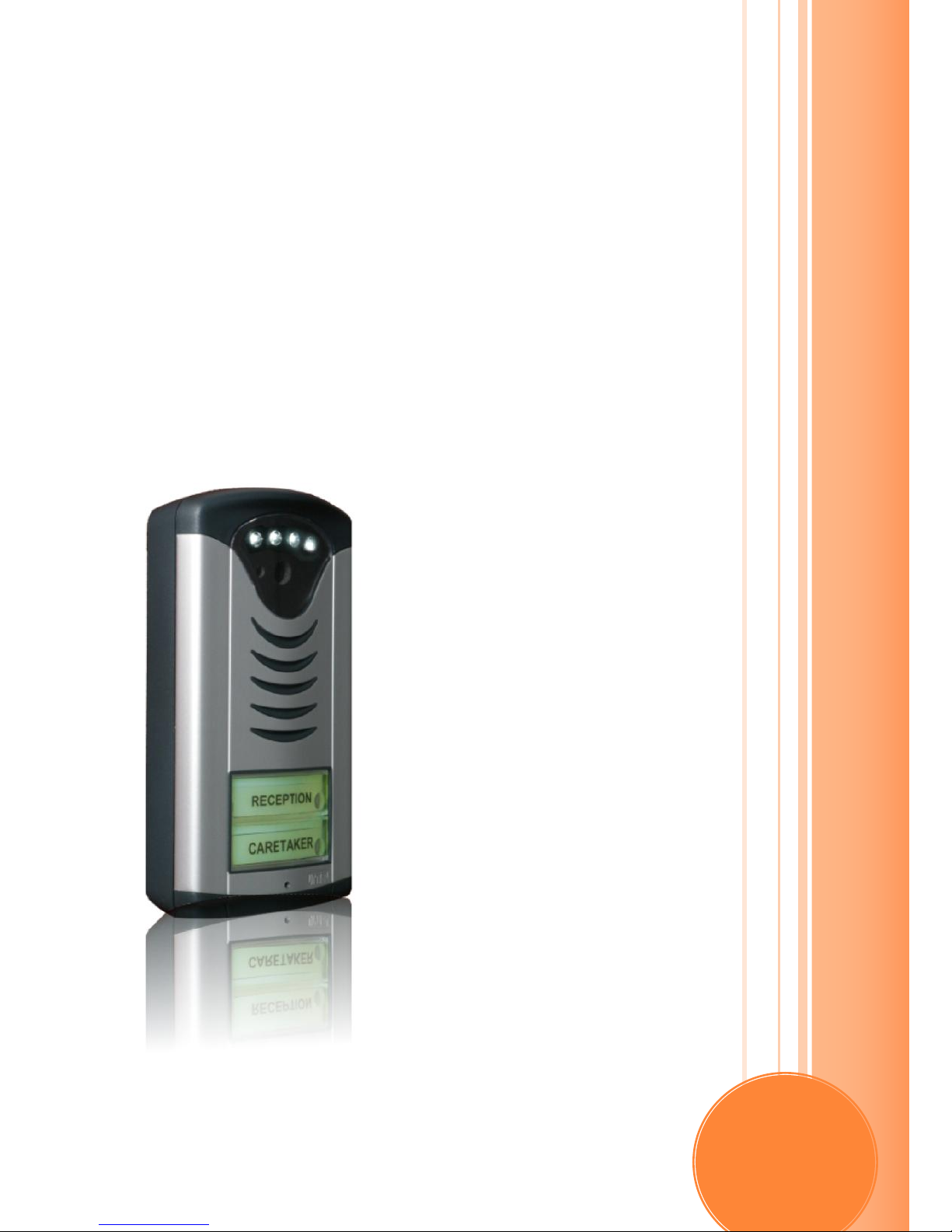
TELSTROM IP
SLENDER VIDEO
DOOR PHONE
Installation Manual
Page 2

www.telstrom.net 1
Overview
Thank you for purchasing the Telstrom IP Door Phone, it is an ideal
door entry solution for apartments, offices or gate control.
The Telstrom IP Video Door Phone can be used to replace traditional
intercoms, by using your existing LAN / Ethernet cabling. It can be
connected to a wide range of devices:
an IP PBX and integrated as a SIP extension of the PBX.
As a SIP trunk / SIP extension from an Internet Telephony
Service Provider (ITSP)
In peer to peer mode. A one to one connection is made between
door phone and PC / SIP desk phone.
The visitor simply presses any of the speed dial buttons on the Door
Phone. Each speed dial button can be programmed with either one or
two numbers for either Day/Night mode or Busy mode.
The two relays can be activated individually after answering a call with
a DTMF code or via the Pop-up application.
Optional H.263 Video of the visitor can be viewed on either a computer
running a Video SIP soft phone (e.g. X-lite), Windows PC running the
Pop-up application, Video Desk Phone (e.g.GXV-3000), Android 2.1
phone or streamed to a Digital Video Receiver (DVR).
Page 3

www.telstrom.net 2
Contents
Benefits: ....................................................................................................... 4
Available Products: ..................................................................................... 5
Available Options: ....................................................................................... 5
Connectivity Options: ................................................................................. 6
Wiring: ......................................................................................................... 7
Power Requirements ............................................................................... 7
Relay Connections ................................................................................... 7
Time Profiles: .............................................................................................. 8
Automatic Day / Night Profile ................................................................ 8
Manual Day / Night Profile ..................................................................... 8
Busy Mode ................................................................................................ 8
Visitor at the Door: ..................................................................................... 9
Tenant Inside The Premises : .................................................................. 10
The tenant receives calls from Visitors at the door and can also place
calls to the Door Phone to listen/view outside the property. .............. 10
Visitor outside at Door Phone, calling tenants phone. ........................ 10
Tenant calling Door Phone. .................................................................. 10
Tenant Leaving / Arriving at Premises ................................................... 11
Available Tenant Video/Audio Devices .................................................... 12
P2P (Peer 2 Peer) or SIP Proxy ................................................................ 13
1.) P2P Mode ....................................................................................... 13
2.) SIP Proxy Mode (registers against a SIP Proxy) ........................ 13
Programming via Web GUI ...................................................................... 14
Network Settings: .................................................................................. 15
Basic Settings ........................................................................................ 15
Page 4

www.telstrom.net 3
SIP Settings ........................................................................................... 16
Audio Codecs .......................................................................................... 16
Video Settings ........................................................................................ 17
Relays ..................................................................................................... 17
Time Options ......................................................................................... 19
Speed Dial Bins / Buttons: .................................................................... 20
User Interface ........................................................................................ 21
System Settings ..................................................................................... 21
View Video ............................................................................................. 22
Audio Levels / Echo Cancellation: ............................................................ 23
Technical Parameters ............................................................................... 24
Electrical Parameters............................................................................ 24
Guarantee conditions: ............................................................................... 25
Page 5

www.telstrom.net 4
BENEFITS:
Works on your existing structured cabling
Power Over Ethernet (POE)
SIP 2.0 protocol
Configuration via Web interface. (remote access via port
forwarding)
Up to 2 speed dial buttons with backlighting
Optional Video Camera video via HTTP streaming or H.263
video
Two time profiles. Day / Night or Busy profile
Modular options
Flush or Surface mount options.
Two NC / NO relays
Variable Volume, Microphone, Echo adjustment (Trim Pots)
Board heating system to avoid condensation.
Opening / Closing Relays via DTMF
Changing Day/Night profile via DTMF
Page 6
www.telstrom.net 5
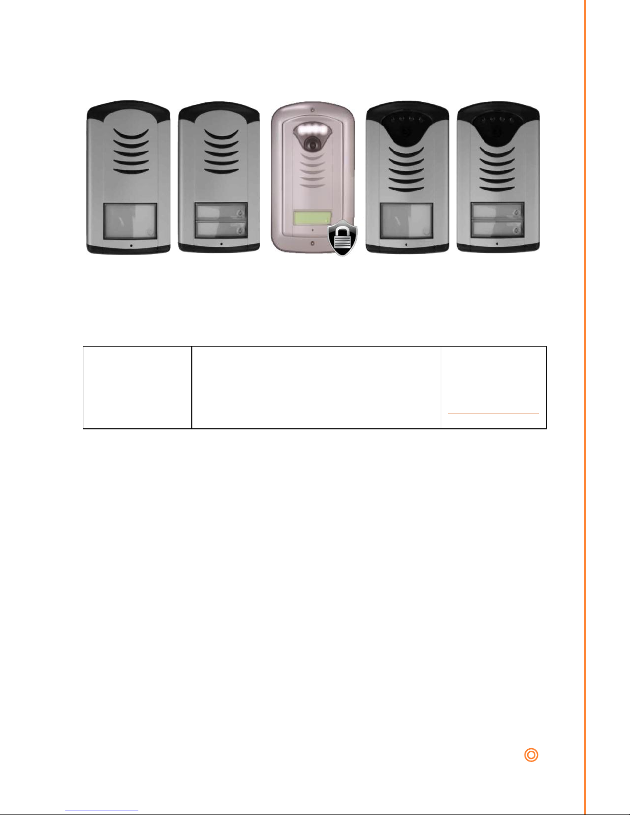
AVAILABLE PRODUCTS:
DF-IP-S-1B DF-IP-S-2B DF-IP-S-1B-C-AV DF-IP-S-1B-C DF-IP-S-2B-C
AVAILABLE OPTIONS:
POP-UP
Windows Pop Application (included) The
application is a video and SIP softphone for
use with the IP door phone.
Download
application and
setup guide from
www.telstrom.net
Page 7

www.telstrom.net 6
CONNECTIVITY OPTIONS:
The IP Door phone offers the following connectivity options:
The audio (SIP) can be connected to either:
A SIP extension off an IP PBX using SIP 2.0
SIP Telephone provider.
Peer two Peer mode: directly between the Door Phone and a
SIP end point using IP addresses e.g. Door Phone to SIP Desk
Phone etc.
The optional video camera can be connected via:
Windows PC running the Telstrom Pop-Up application.
Computer with a SIP video softphone
H.263 Video Desk Phone. E.g. GXV-3000
Android Phone 2.1 or later
SIP Telephone provider running H.263.
HTTP streaming
Two relays:
Each relay can be controlled individually or in a sequence. Both
relays are (NO) Normally Open or (NC) Normally Closed.
The called person on a handset, answers the visitors call and
enters a code to unlock either of the relays.
The called person using the Windows Pop-up application clicks
either one of the relay opening buttons.
Page 8
www.telstrom.net 7
WIRING:
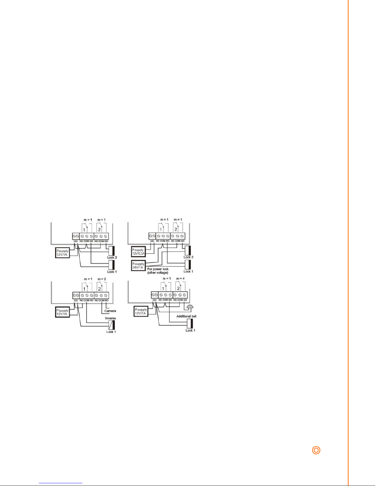
Power Requirements
It is necessary to use either one of the following options:
AC voltage of a min. 10VAC to a maximum of 15VAC or
DC voltage of min. 12VDC to max. 18VDC.
POE (Power of Ethernet) IEEE 802.3af max load 350 mA
The voltage must be connected to the terminal marked “12V”. The
maximum load will not exceed 300mA. This source can be also used for
powering lock(s), but you must also add the load demand of the locks.
Generally a 12V/1A DC power supply meets most demands.
Relay Connections
On the main board there are
two relays and each relay has
two options for wiring locks /
switches. Either “NO”
Normally Open or “NC”
Normally Closed” depending
on your requirements. The
contacts on both relays are
galvanically isolated from each
other and from other circuits.
Page 9

www.telstrom.net 8
TIME PROFILES:
The IP Door Phone supports three time profiles:
Automatic Day / Night profile hands over at a set time.
Manual Day / Night profile change over via DTMF tones
Busy Profile
Automatic Day / Night Profile
In Day / Night profile it allows each speed dial button to have two
phone numbers stored against it. The first number for office hours and
the second for after hours. This mode changes at a predetermined time
and the Door Phone uses the Network Time Protocol (NTP) to sync its
clock.
Example: If a visitor presses button 1 during the day, the door phone
calls Homer on 201. If it is after hours, and the visitor press button 1,
the door phone calls Marg on her mobile 12345678.
Manual Day / Night Profile
This mode is the same as automatic profile except the change from day
to night profile is controlled manually by calling the Door Phone and
entering 10 (default) for Day Mode and 11 (default) for Night mode.
Busy Mode
In this mode, if the first number that is called from a speed dial button
e.g. 201 and if 201 is busy, then it will call the second stored number
against that speed dial button, e.g. Marg on her mobile 12345678.
Also, if the visitor presses a button twice it will call the second number,
eg. Marg on her mobile 12345678.
Page 10

www.telstrom.net 9
VISITOR AT THE DOOR:
When a visitor arrives at the door, they have three options to contact
the required tenant depending on the Door Phone configuration.
1. Push a Speed Dial Button with assigned phone number.
The Door Phone will place a call to the desired tenants number (or IP
address in Peer to Peer mode) depending what Mode it is currently in
(refer to Time Profile).
Page 11

www.telstrom.net 10
TENANT INSIDE THE PREMISES:
The tenant receives calls from Visitors at the door and can also place
calls to the Door Phone to listen/view outside the property.
Visitor outside at Door Phone, calling tenants phone.
The tenant who answers the call from the Door Phone Visitor can:
Have a conversation with the visitor
View the visitor at the door (if using the optional Video)
Open either 1,2 or both relays. E.g. Open the Door (relay 1) and
switch the light on (relay 2)
Terminate the call
Tenant calling Door Phone.
The Tenant can call the Door Phone and do the following:
Have a conversation with outside (intercom)
View the visitor at the door (if using the optional Video)
Open either 1,2 or both relays. E.g. Open the Door (relay 1) and
switch the light on (relay 2) via DTMF or PC
Change Time Profile e.g.Day/Night or Busy via DTMF or PC
Hangup the call, which hangs up the Door Phone via DTMF or
PC
Page 12

www.telstrom.net 11
TENANT LEAVING / ARRIVING AT PREMISES
The tenant can change day / night profiles manually, as well as open
and close relays when at the door phone by entering either:
A code via pressing button 1 and 2 in a set sequence. Refer
Relays 2.
For example the tenant could change to night mode, when he leaves his
Premises, so when visitors press the button on the door phone, calls go
through to the (second group speed bin) to the tenants mobile.
Page 13

www.telstrom.net 12
AVAILABLE TENANT VIDEO/AUDIO DEVICES
There are few different phones and video phones that a tenant can use
inside their Premises.
IP Desk Phone running SIP 2.0 e.g. Aastra, Cisco, Polycom etc
IP Video Desk Phone running SIP 2.0 and H.263 Video Protocol.
e.g. Tornado M20, Grandstream GXV-3000, Yealink vp-2009p,
Tanberg E20,
Computer based Soft Phone running SIP 2.0. e.g. Telstrom
Video Pop-up, Counterpath Bria, X-lite etc.
Computer based Soft Phone running SIP 2.0 and H.263 Video
Protocol. e.g. Telstom Video Pop-up, Counterpath Bri, X-lite etc.
Analogue Telphone Adapter (ATA) – converts SIP from Door
Phone to an FXS port to connect a traditional handset. E.g.
Linksys PAP2T, Grandstream HT286. IP Video sent to PC.
Digital Video Receiver (DVR) for streaming / recording video
and streaming to TVs etc
Page 14
www.telstrom.net 13
P2P (PEER 2 PEER) OR SIP PROXY
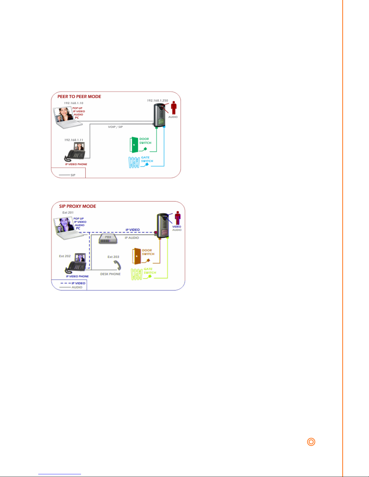
The Door Phone supports two modes of VOIP operation.
1.) P2P Mode
In this mode the Door Phone
communicates directly to the
Tenants device. There is no
server / IP PBX required in this
mode. The Door Phone calls IP
addresses of the devices it needs
to communicate with. Set DIP
switch 2 (up)
2.) SIP Proxy Mode (registers against a SIP Proxy)
In this mode the Door Phone
registers against either an IP
PBX or an ITSP as a SIP
extension. The DoorPhone is
seen as a normal extension of
the PBX and can make and
receive calls. Set DIP switch 2
(down)
Page 15
www.telstrom.net 14
PROGRAMMING VIA WEB GUI
To setup the door phone you will need to
change your PCs IP address to 192.168.1.x to
be able to configure the Door Phone on
192.168.1.250 (default).
Point your browser to http://192.168.1.250
Username: admin
Password: 1234
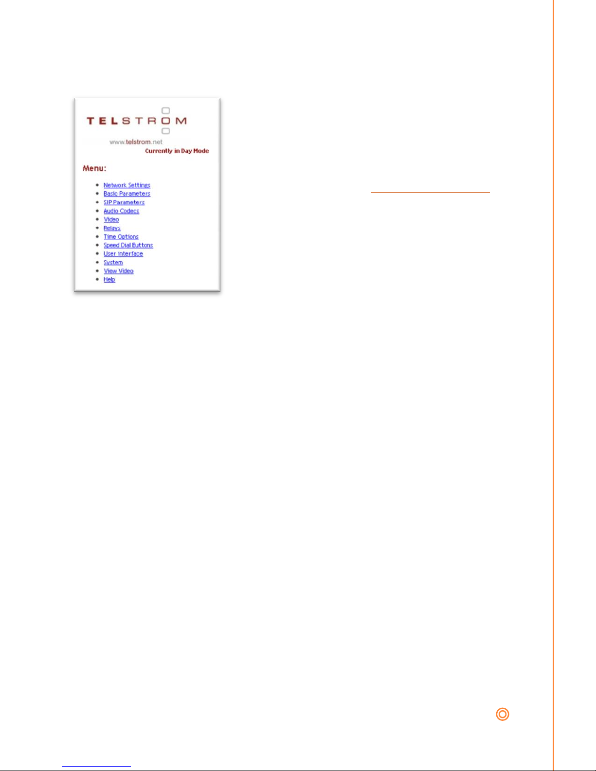
The first page will show the view of the video
camera (if installed). Click setup to configure
the Door Phone.
Page 16
www.telstrom.net 15
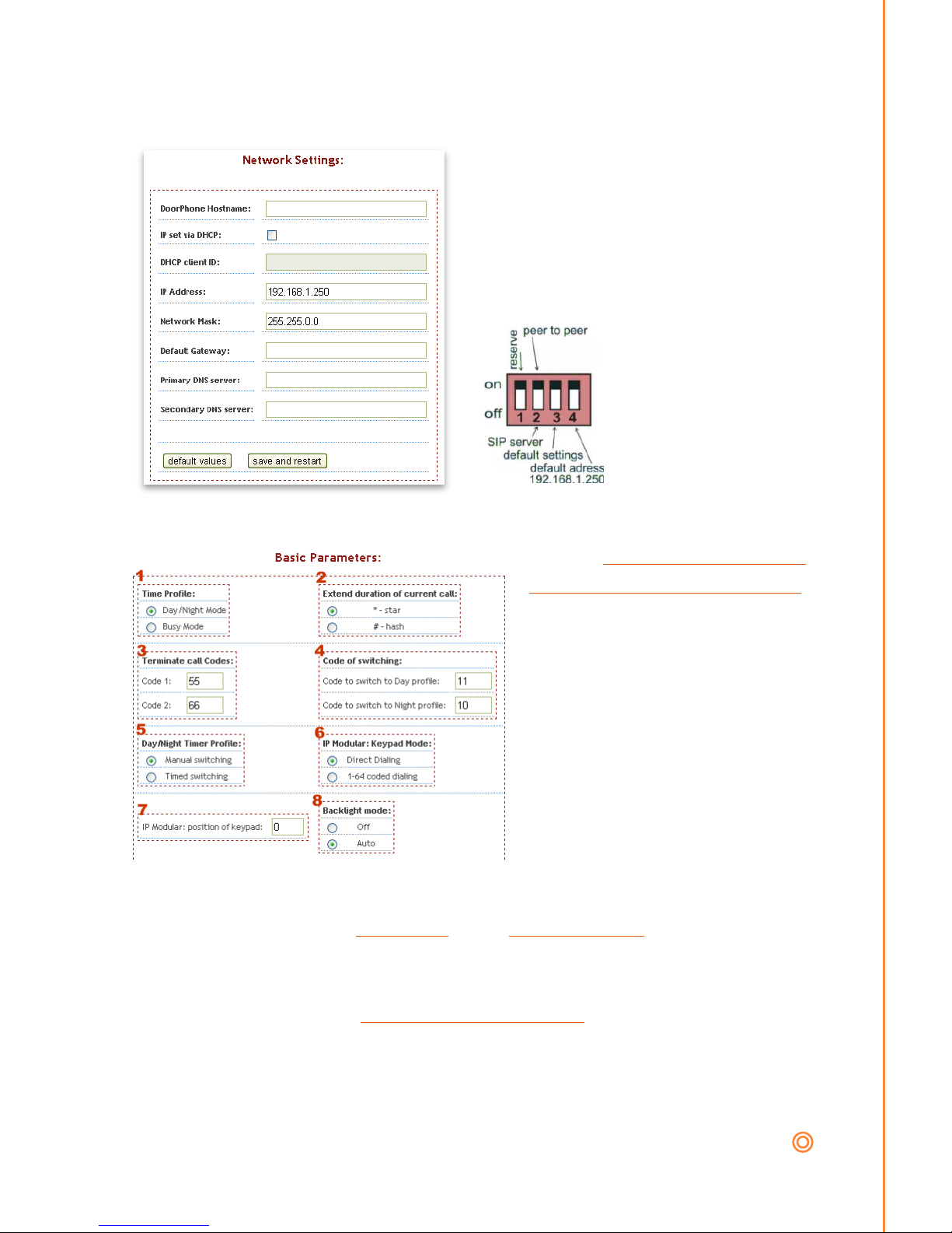
Network Settings:
Ask your network administrator
for the relevant network settings to
configure the Door Phone. We
strongly suggest assigning a static
IP address and not “IP set via
DHCP”
To default the IP
address of the Door
Phone: DIP switch 4
(down). Default settings
DIP switch 3 (down).
After power up, push the
DIPs switches back up.
Basic Settings
1. Change between Day
Night Mode and Busy Mode.
2. The tenant can enter
either a “*” or “#” to extend
the current call duration.
3. The tenant can enter
codes during a conversation
to terminate the current call.
4. The tenant can
manually change the profile
between Day or Night by
entering the code.
5. The Door Phone can either switch profiles between Day and
Night profiles either a.) Manually or b.) Automatically.
6. If the optional keypad (IP Modular only) is attached, then
choose if you want a.) Direct dialing – e.g. calling extensions via the
keypad. Or b.) Dialing a speed bin number 1-64.
7. If the optional keypad (IP Modular only) is attached, what is
the installed position of it. i.e. What module number / position has the
keypad been installed.
Page 17
www.telstrom.net 16
SIP Settings
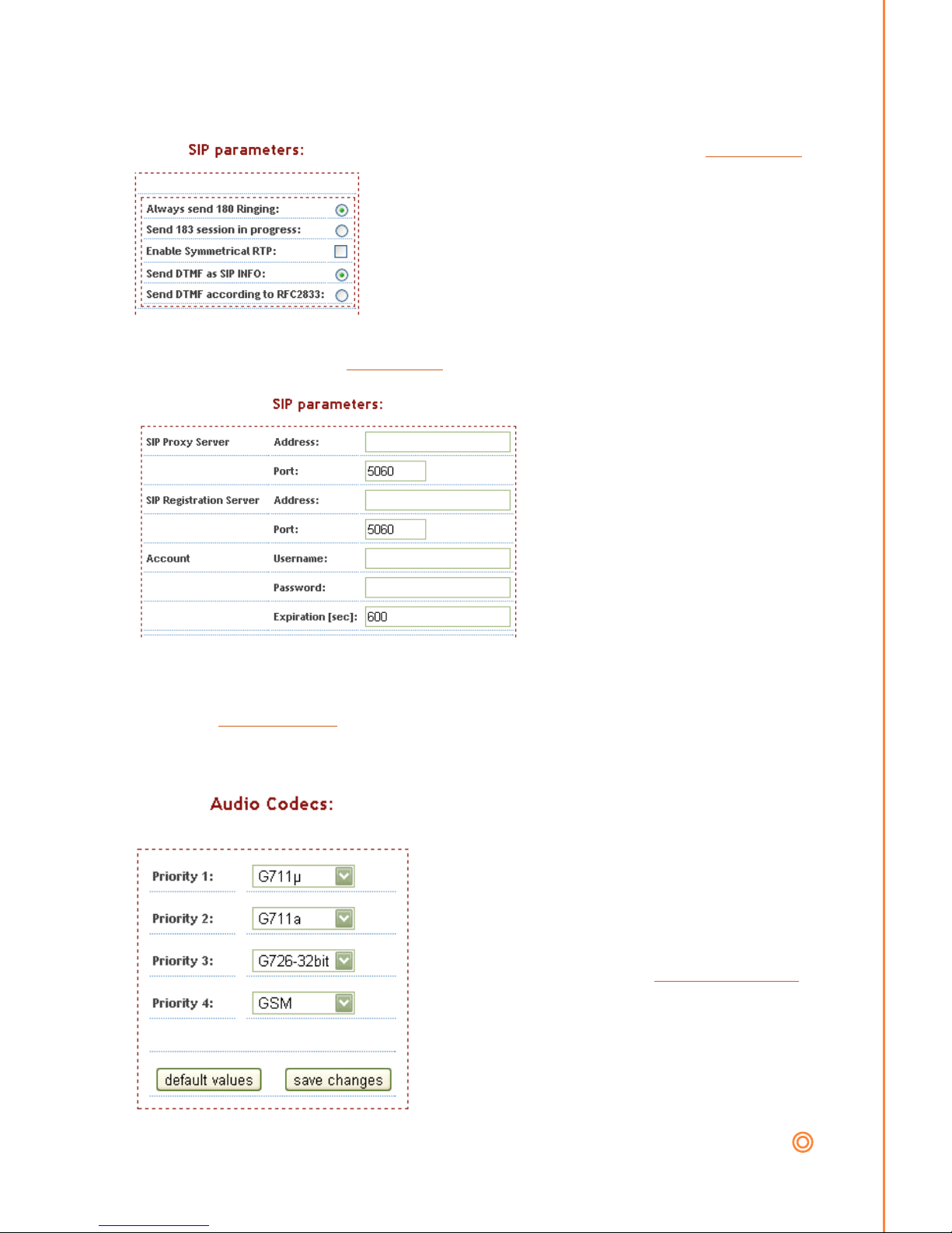
If you have set DIP switch 2 (up) P2P Mode
then you will see limited settings as the
Door Phone will just be contacting via IP
addresses.
Change these settings to match your IP
PBX, ITSP.
If DIP switch 2 (down) SIP Proxy, you will see the following screen.
Ask your IP PBX or ITSP
administrator for the
relevant settings. In most
cases the SIP Registration
Server Address / Port are
not required. After saving, a
prompt will show either
“Registration Successful” or
“Registration Failed”.
If the registration failed check, the user credentials, IP address and
available audio codecs.
Audio Codecs
Ask your IP PBX or ITSP
administrator for the relevant codes to
be used. These should match the
device you are connecting to. To
change the microphone and speaker
gains as well as adjust the levels of the
echo canceller refer to Audio Volumes.
Page 18
www.telstrom.net 17
Video Settings
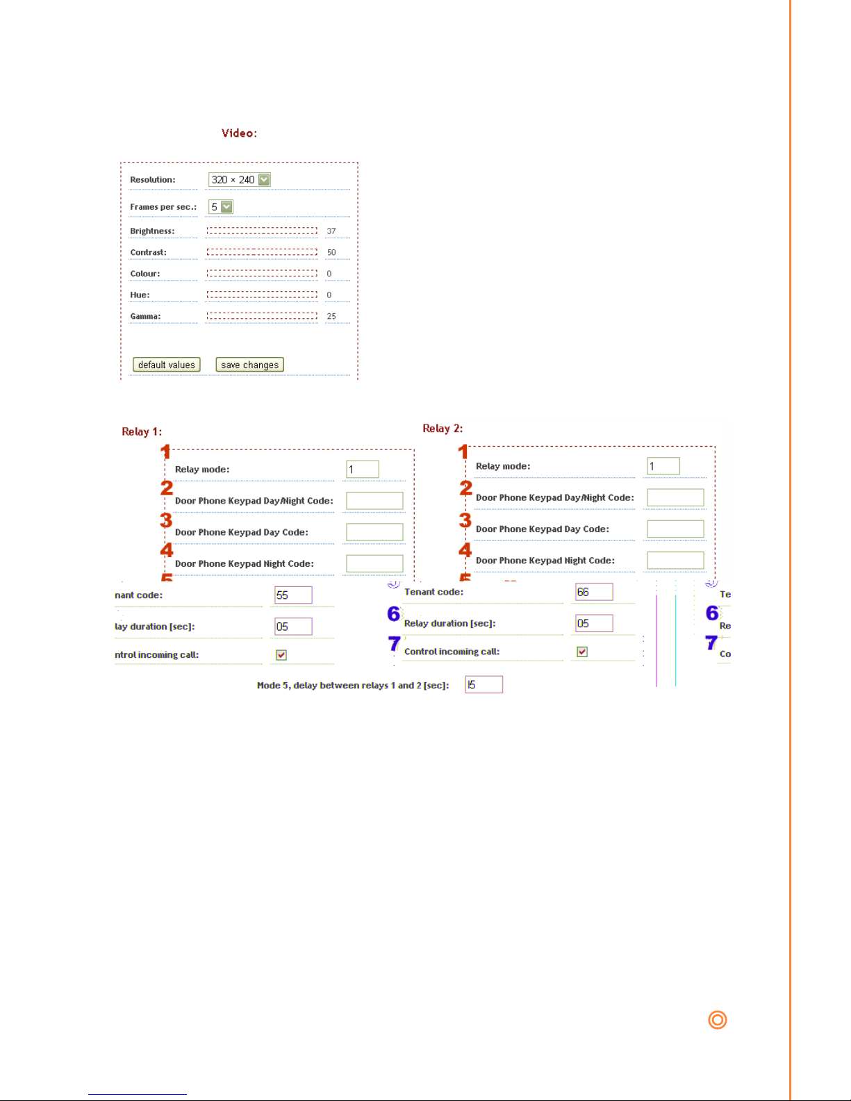
Here you can change the resolution and
frame rate of the video stream to the
web browser and receiving video clients.
Relays
The Door Phone has two normally closed NC or normally open NO
relays .
1 Relay modes:
1) Switch Mode: In this mode the relevant relay will be activated for a
period of seconds set in 6 when the tenant code 5 has been sent or
the access code has been entered.
2) Camera Mode: In this mode the relevant relay will close when the
tenant answers a call from the door phone and the relay will open
when the call is hung-up.
Page 19

www.telstrom.net 18
3) Lighting Mode: The relay will close when the tenant answers the
call from the door phone, and will remain closed for a period of 6 x
seconds after the call is hung-up.
4) Bell Mode: The relay will close when someone pushes a button on
the door phone and will open after a period of 6 x seconds.
5) Sequence Relay Mode: In this mode relay 1 is activated for 6 x
seconds, then Relay 2 is activated for 6 x seconds. Whenever Relay
1 is activated it follows the sequence. Relay 2 can be opened
separately.
2 External Day/Night Change Over Code: [2 to 6 digits]
The tenant when outside the property can change the day/night mode
from the door phone by pushing the buttons 1 & 2 in the correct
sequence. E.g. The tenant is going on holiday and the night mode
number is forwarded to the tenants mobile, so changing to night mode
“121121” all visitors at the door phone would call the tenants mobile.
Requires a two button IP Door Phone.
Tips: Don’t use similar codes for external use. E.g. 12221 & 12222
5 Tenants phone codes: [1-2 digits]
The tenant can open relay 1 or 2 individually or at the same time
depending on the code entered. Setting the same code for both relays
will open both relays when the tenant enters the DTMF command from
their handset. The tenant can activate the relays during a call to or
from the door phone. To use a single digit command prefix the code
with “*” e.g. *1
6 Relay duration [in seconds 01 – 99]
7 Incoming call control
Example: If the tenant gave access to a visitor to park their car, and the
electric gate opens and while this happens the tenant accidently enters
Page 20
www.telstrom.net 19
a code for a relay to close the gate which damages the car. Turning this
off would avoid the issue.
8 Relay duration for mode 5, between relay 1 and relay 2. [in seconds
01 – 99]
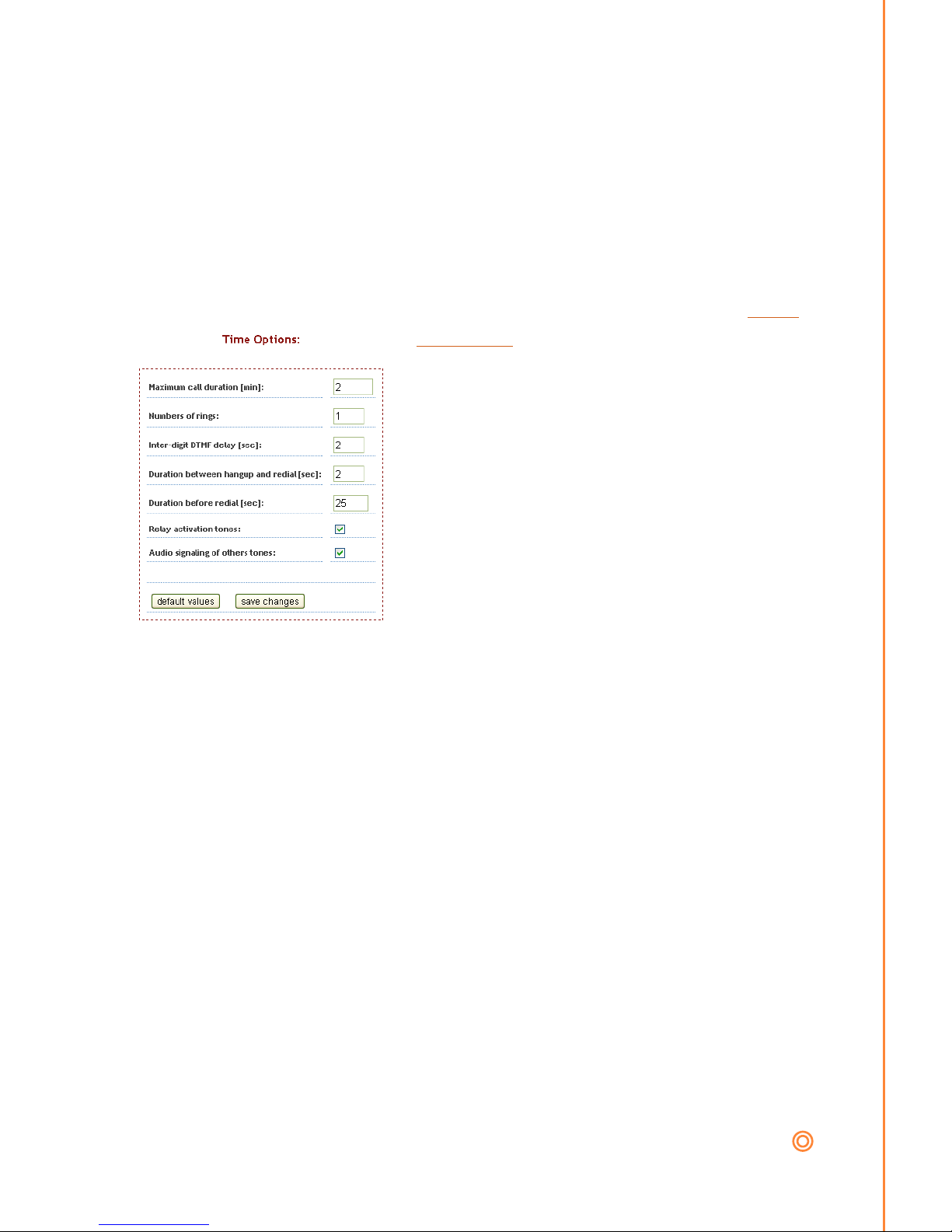
Time Options
Maximum call duration [minutes], the call can be extended refer Basic
Settings 2.
When the tenant calls the door phone,
the number of rings before answering the
call.
The DTMF delay of the door phone
accepting digits from the tenant between
each keypress.
The minimum duration between hanging
up and placing the next call.
The delay in seconds to place the next call if the first call is unanswered
after x seconds.
Signal with a tone to the tenant when a relay has been opened and
closed.
Signal with a tone to the tenant when other events occur.
Page 21
www.telstrom.net 20
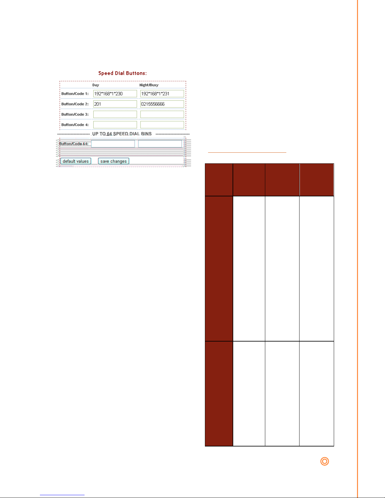
Speed Dial Bins / Buttons:
The Speed Dial Bins / Buttons
table allows you to set numbers
against each button. E.g.
Visitor presses button 1, it calls
201. Bins 3-64 do not apply to
the IP slender.
Example Table of Speed Dials.
(refer to Time Profile)
Speed
Bin/B
utton
Option
1 (Day)
Option
2
(night/b
usy)
1)
e.g.
SIP
Prox
y
mod
e
201
123456
78
If mode
is
(Day/Ni
ght)
then
call
123456
78 after
hours.
If mode
is
(Busy)
then
call
123456
78 if
201 is
busy.
2)
e.g.
P2P
mod
e
192.16
8.10.16
192.168
.10.150
If Door
Phone
set as
Peer to
Peer. If
mode is
(Day/Ni
ght)
then
call
192.168
.10.150
after
Page 22
www.telstrom.net 21
hours.
If mode
is
(Busy)
then
call
192.168
.10.150
if
192.168
.10.16
is busy.
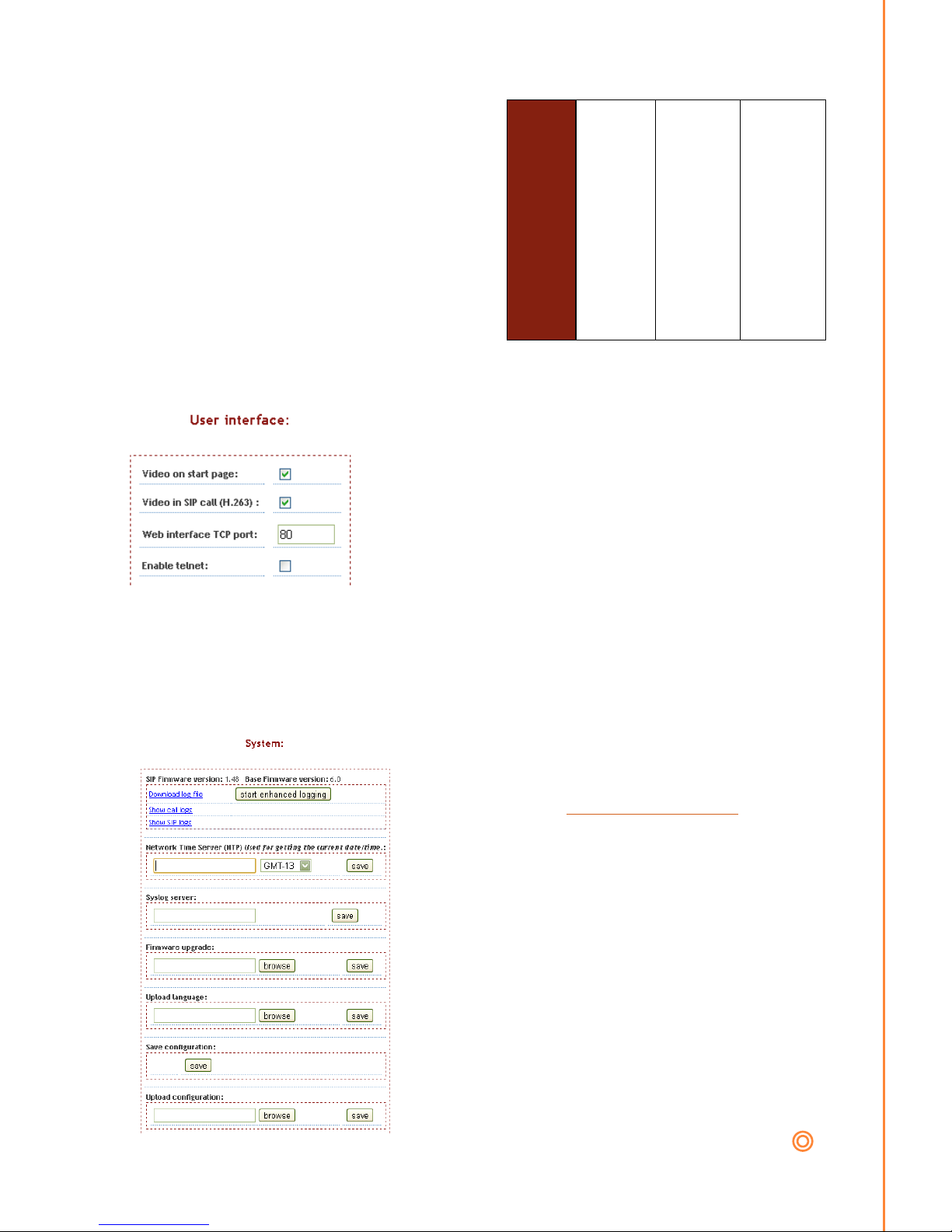
User Interface
These are basic settings depending on your
setup.
The door phone Web GUI can be accessed
remotely by asking the IT administrator to
forward a TCP port to the static IP address
of the door phone. This port can be changed to
the IT administrator’s requirement.
System Settings
At the top of the screen displays the
current firmware and SIP firmware
versions, check www.telstrom.net for
later versions.
To try and fault find problems you can
start enhanced logging and then place
the call and view the log file to diagnose
the problem. It is always good practice to
replicate the situation using a SIP soft
phone like x-lite before raising a support
ticket.
Page 23

www.telstrom.net 22
If you require automatic time changes between day and night profiles
you will require to enter a relevant NTP server address to your
location.
Note: Winter/ Summer time changes are not automatically changed by
the door phone, but should be provided by the NTP server.
You can backup save the current configuration and load previous
configurations.
View Video
The view video page shows a JPG stream of images coming from the
Door Phone camera. The resolution, frame rate etc can be changed.
Refer to Video Settings.
Page 24

www.telstrom.net 23
AUDIO LEVELS / ECHO CANCELLATION:
The default levels in most cases should be sufficient, if you do
adjust make a note of the factory setting. The microphone,
speaker and echo canceller levels can all be manually adjusted by
turning the trim pots which are located on the top section of the main
board. Make the adjustments while on a call in the environment that
will be used.
Page 25
www.telstrom.net 24
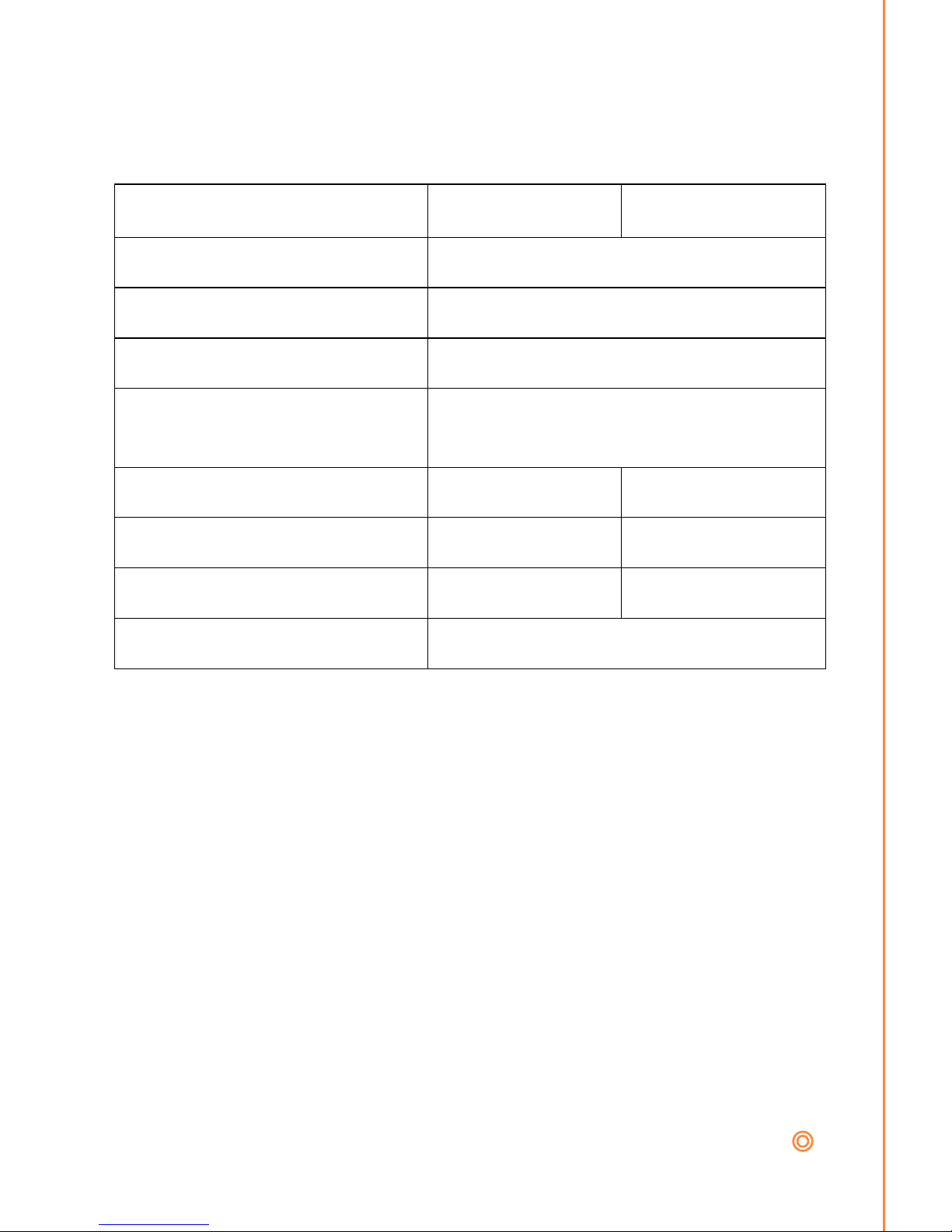
TECHNICAL PARAMETERS
Electrical Parameters
Parameter
Value
Conditions
Communication interface
Ethernet 10BaseT, 100BaseTx
VoIP protocol supported
SIP
Band width
300Hz – 3400 Hz
Power supply of lighting
through, switches and heating
12VDC ± 2V, 10-12VAC ± 2V
Max. consumption
300mA
12VDC
Max. voltage of switch contact
48V
at I < 1A
Max. current of switch contact
2A
at U < 30 V
Operational temperature
-20 to +50°C
Page 26

www.telstrom.net 25
GUARANTEE CONDITIONS:
This product was shop-checked. The producer guarantees that this
product will keep the features described in these operating instructions
in the course of guarantee provided the user follows instructions
described in the operating manual.
If making a claim within the guarantee period, please contact your
dealer. Only the producer will make guarantee repairs. Request a
Return Material Authorisation number describing the reason for claim,
proof of purchase and your exact address and contact details. You will
then be advised of corrective action to be taken.
The guarantee does not include:
mechanical, thermal, chemical and other damages caused by
user’s activities or location
defects caused by natural disasters
defects caused by repair or modifications carried out by user or
other unauthorised person
willful damage of product
incorrect use of product caused by other use than specified in
operating manual (e.g. installation, programming)
damage caused during product transport to customer and from
supplier
 Loading...