

Page 1

Telstra Commander@ E1
05/208+
Installation and Maintenance Manual
DOC - E+ - IM
546/261
(ISSUE 1)
celstra
Page 2

COPYRIGHT 1995 Telstra Technologies Pty Ltd
Telstra Technologies Pty Ltd, is a Standards Australia Quality Endorsed Company. This work is
copyright. All rights reserved. Other than for purposes and subject to conditions prescribed under the
Copyright Act, no part of it may in any form or by any means (electric, mechanical, microcopying,
photocopying, recording or otherwise) be reproduced, stored in a retrieval system or transmitted
without prior permission from Telstra Technologies Pty Ltd.
All enquiries should be addressed to:
Telstra Technologies Pty Ltd
A.C.N.006841 345
Locked Bag 10
HAWTHORN VIC 3 122
AUSTRALIA
0
Registered Trade Mark of Telstra Corporation Limited A.C.N. 05 1775 556
Page 3
Table of Contents
I -
Chapter One - Introduction to the Commander
E105/208+
System
Introduction
.............................................................................................................................. l-l
General Description
.................................................................................................................
I-
1
Keystations
.....................................................................................................................
1 -
1
Power and Termination Unit
............................................................................................
l-2
Power-fail
........................................................................................................................
l-3
Door Station
...................................................................................................................
l-3
System Features
......................................................................................................................
l-5
Keystations
.....................................................................................................................
l-5
Visual Indications
............................................................................................................
l-5
Programmable Facilities
...................................................................................................
1 -
5
SystemFacilities
......................................................................................................................
l-6
Incoming Calls
................................................................................................................
l-6
During a Call
................................................................................................................... l-6
outgoing Calls
................................................................................................................
1-7
Internal Calls
...................................................................................................................
l-8
Equipment
.......................................................................................................................
l-9
Miscellaneous
.................................................................................................................
l-9
Chapter Two - Power and Termination Unit
Introduction
.............................................................................................................................
2-l
General Description
.................................................................................
.
...............................
2-
1
Power and Terminating Board
.........................................................................................
2-2
Optional Facilities Board (Optional)
.................................................................................
2-2
Circuit Blocks - Power and Terminating Board
.........................................................................
2-3
Transformer
...................................................................................................................
.2 - 3
Power Supply
.................................................................................................................
2-3
Electronic Choke
...........................................................................................................
.2-3
Power-fail
.......................................................................................................................
.2-3
Exchange Line Protection
...............................................................................................
.2-3
System Bus
.....................................................................................................................
2-3
Circuit Blocks - Optional Facilities Board..
...............................................................................
2-5
Microcomputer Unit (MCU)
..........................................................................................
.2-5
Data Transmit and Receive
.............................................................................................
.2-5
Door Station Interface
.....................................................................................................
2-5
External Music Source Interface
.....................................................................................
.2-5
Commander E105/208+ Installation and Maintenance Manual
Table of Contents - i
Page 4

Chapter Three - Keystations
Introduction
.............................................................................................................................
3 - 1
General Description
.................................................................................................................
3 - 1
Keystation Main Board
...................................................................................................
3-2
Hold and Ring Detect Board
...........................................................................................
3-2
Keypad Assembly
...........................................................................................................
3 - 2
Circuit Blocks
..........................................................................................................................
3-3
Microcomputer Unit Circuit (MCU Circuit)
....................................................................
.3-3
Power Supply
.................................................................................................................
3-3
Isolation Transformer
.......................................................................................................
3 - 3
Data Transmit and Receive
..............................................................................................
3-4
Speech Circuit
................................................................................................................
3-4
Tone Generator
...............................................................................................................
3 -4
Audio Selector
................................................................................................................
3 -4
Audio Amplifier
...............................................................................................................
3 -4
Line Access Circuit
........................................................................................................
.3-4
HRDB-E Board (In Master Keystation)
..........................................................................
3-4
Chapter Four - Hardware Installation
Introduction
.............................................................................................................................
4-
1
Component Safety Precautions
................................................................................................
4-
1
Installation Checklist
................................................................................................................
4-2
Installation Procedures
.............................................................................................................
4-3
Sales Form Completion/Equipment Ordering
.................................................................
.4-3
Locate and Mount Equipment
.........................................................................................
.4-3
Optional Facilities Board Installation (OFB-E)
...............................................................
4- 11
Connect and Terminate Cables
.....................................................................................
.4-
12
Power-Fail Telephone
..................................................................................................
.4-
17
Protective Earth
...........................................................................................................
.4-
17
General Procedure
.................................................................................................................
4-
18
Power Up.. ..................................................................................................................
.4-18
Check Cabling
.............................................................................................................
.4-
18
Power Down
...............................................................................................................
.4-
18
Plug in Keystations
.......................................................................................................
.4-
18
Keystation Self Test
.....................................................................................................
.4-
18
Test Mode Entry
..........................................................................................................
.4-
18
LEDTests..
..................................................................................................................
.4-19
Programming..
..............................................................................................................
.4-20
Defective Equipment
....................................................................................................
.4-20
Tab/e of Contents
-
ii
Page 5
__
Chapter Five - System Programming
Introduction
.............................................................................................................................
5-l
General Description
................................................................................................................. 5-l
Programming Hardware Locations
...........................................................................................
5-l
DIP Switches
..................................................................................................................
5-l
General Programming Procedure
..............................................................................................
5-3
Keystation Intercom Address
.........................................................................................
.5-3
Master Page-In
...............................................................................................................
5-4
Keystation Access Class
.................................................................................................
5-4
Ring Line 1
.....................................................................................................................
5-6
RingLine
..................................................................................................................... 5-6
DialType
.......................................................................................................................
.5-7
Auto Pause Insert
...........................................................................................................
.5-7
Music-On-Hold
.............................................................................................................
.5-8
Background Music
.........................................................................................................
.5-9
InitialiseandReset
.................................................................................................................
5-10
Access Class Restriction
...............................................................................................
5-10
Exchange Line Auto Answer
.........................................................................................
5-11
Headset Mode
.............................................................................................................
.5-
12
Programming summary
..........................................................................................................
5-13
Software Programming Records
....................................................................................
5-13
Chapter Six - Functional Tests and Maintenance
Introduction
.............................................................................................................................
6-l
General Description
.................................................................................................................
6-l
System Tests and Repair Actions
.............................................................................................
6-2
Key station Installation
.....................................................................................................
6-2
* Exchange Line Seizure
..................................................................................................
6-3
* Incoming Exchange Call
...............................................................................................
6-3
Off-Hook Signalling
........................................................................................................
6-3
Volume Control
...............................................................................................................
6-3
Answering Exchange Call
................................................................................................
6-3
Automatic Answering Exchange Call
................................................................................
6-4
* Outgoing Exchange Call
...............................................................................................
6-4
Decadic to Tone Signalling
...............................................................................................
6-4
Hold
...............................................................................................................................
6-4
Music-On-Hold
..............................................................................................................
6-4
Hold Automatic Ring Back
.............................................................................................. 6-4
* Last Number Redial
....................................................................................................
.6-4
Abbreviated and Speed Dialling
.......................................................................................
6-5
Commander E105/208+ Installation and Maintenance Manual
Table of Contents -
ii/
Page 6

System Memory Back-Up
..............................................................................................
6-S
* PABX Recall
...............................................................................................................
6-5
* Paging
..........................................................................................................................
6-5
Do Not Disturb
...............................................................................................................
6-5
Intercom Signal or Voice Call
..........................................................................................
6-S
Intercom Answering
........................................................................................................
6-5
On-Hook Dialling
............................................................................................................
6-5
* Exchange Line Conference
...........................................................................................
6-6
* Background Music
.......................................................................................................
6-6
*
Door Station
................................................................................................................
6-6
*
Power-fail Telephone
...................................................................................................
6-6
Centel Features
..............................................................................................................
.6-6
Maintenance
............................................................................................................................
6-7
Test Equipment
...............................................................................................................
6-7
Voltage Test Points
..........................................................................................................
6-7
General
...........................................................................................................................
6-8
Fault Finding Tables
.................................................................................................................
6-8
Repair Procedures
.................................................................................................................
6-
15
Printed Board Assemblies
(PBA’s)
...............................................................................
.6-
15
Appendix A - System Characteristics
System Capacities and Limits
. . . . . . . . . . . . . . . . . . . . . . . . . . . . . . . . . . . . . . . . . . . . . . . . . . . . . . . . . . . . . . . . . . . . . . . . . . . . . . . . . . . . . . . . . . . . . . . . . .
A- 1
System Specifications
. . . . . . . . . . . . . . . . . . . . . . . . . . . . . . . . . . . . . . . . . . . . . . . . . . . . . . . . . . . . . . . . . . . . . . . . . . . . . . . . . . . . . . . . . . . . . . . . . . . . . . . . . . . . .
A-2
Electrical
. . , . . . . . . . . . . . . , . . . . . . . . . . , . . . . . . . . . . . . . . . . . . . . . . . . . . . . . . . . . . . . . . . . . . . . . . . . . . . . . . . . . . . . . . . . . . . . . . . . . . . . . . . . . . . . . . . . . . . . .
A-2
Environmental
. . . . . . . . . . . . . . . . . . . . . . . . . . . . . . . . . . . . . . . . . . . . . . . . . . . . . . . . . . . . . . . . . . . . . . . . . . . . . . . . . . . . . . . . . . . . . . . . . . . . . . . . . . . . . . . .
A-2
External Music- On-Hold
. . . . . . . . . . . . . . . . . . . . . . . . . . . . . . . . . . . . . . . . . . . . . . . . . . . . . . . . . . . . . . . . . . . . . . . . . . . . . . . . . . . . . . . . . . . . . . .
A-2
Dialling
. . . . . . . . . . . . . . . . . . . . . . . . . . . . . . . . . . . . . . . . . . . . . . . . . . . . . . . . . . . . . . . . . . . . . . . . . . . . . . . . . . . . . . . . . . . . . . . . . . . . . . . . . . . . . . . . . . . . . . . .
...
A-2
Dimensions and Weight
. . . . . . . . . . . . . . . . . . . . . . . . . . . . . . . . . . . . . . . . . . . . . . . . . . . . . . . . . . . . . . . . . . . . . . . . . . . . . . . . . . . . . . . . . . . . . . . . . . A-2
Appendix B - Parts Serial Item and Code list
Central Equipment
...................................................................................................................
B- 1
Keystations
.............................................................................................................................
B-
1
Miscellaneous Items
.................................................................................................................
B-l
Maintenance Parts
...................................................................................................................
B-2
Documents
..............................................................................................................................
B-2
Appendix C - System User Guide
Table of Contents -
iv
Page 7
Table of Illustrations
IL0
1 -
System Block Diagram
..................................................................................................
l-4
IL02 - PTU
.............................................................................................................................. 2-l
IL03 - PTB-E Circuit Block Diagram
........................................................................................
2-4
IL04 - OFB-E Circuit Block Diagram
.......................................................................................
2-6
IL05 - E
105+
and E208+ Keystation
............
.
..........................................................................
3-2
IL06 - Keystation Circuit Block Diagram
..................................................................................
3-5
IL07 - System Order Form..
.....................................................................................................
4-4
IL08 - Limitations To Wall Mounting
.........................................................................................
4-5
IL09 - Plug-Pack Dimensions
...................................................................................................
4-6
IL 10 - Power And Termination Unit Dimensions
........................................................................
4-7
IL 11 - Power and Termination Unit Mounting
............................................................................
4-7
IL1 2 - Sale/Rental Identifying Window
.....................................................................................
.4-8
IL 13 - Installing The Handset Rest
............................................................................................ 4-9
IL 14 - Keystation Wall Mounting Dimensions
..........................................................................
4-10
IL 15 - Wall Mounting the Keystation
......................................................................................
4-10
IL 16 - Wall Mounting Dimensions For Door Stations
..............................................................
4-
1 1
IL
IL
IL
7 - Commander E
105/208+
Cabling Scheme
...................................................................
.4-
12
8 - Bus Length
..................................................................................................................
4-13
9 - Example Of Allowable Keystation Distances
..............................................................
.:
4- 13
IL20 - Example Of Unacceptable Cabling Scheme
..................................................................
4- 14
IL2
1 -
Power and Termination Unit Terminations
.....................................................................
4-14
IL22 - Modular Socket (KRONE Type)
.................................................................................
4-16
IL23 - Keystation DIP Switches (In Default Settings)
................................................................
5-2
IL24 - No Master Page-In
.......................................................................................................
5-4
IL25 - Program - Local Calls Only
...........................................................................................
5-6
Commander
E105/208t
Installation and Maintenance Manual
Table of
Illustrations -
i
Page 8

IL26 - Program - Ring On Line
1
..............................................................................................
5-6
IL27 - Program - No Ring On Line 2
........................................................................................ 5-6
IL28 - Program - DTMF Dialling
..............................................................................................
5-7
IL29 - Program - Auto Pause Insert..
........................................................................................
5-7
IL30 - Music-On-Hold Links
...................................................................................................
5-8
IL3 1- Program - Internal, External, and No Music-On-Hold
....................................................
5-9
IL32 - External Music-On-Hold Setting on
OFB
.......................................................................
5 -9
IL33 - Internal or No Music-On-Hold Setting on OFB
.............................................................
5-9
Table of
Illustrations -
ii
Page 9
Table of Tables
-
Table1-
Bus Cabling
.............................................................................................................
4-l
Table 2 - Keystation Bus Cabling Terminations
.....................................................................
.4
- 15
Table 3 - Door Station Terminations
.4
-
.....................................................................................
16
Table 4 - Keystation Voltages
...............................................................................................
4-
18
Table 5 - Self Test Key Sequence and LED Responses
........................................................
4-
19
Table 6 - DIP Switch 2 Keystation Options..
...........................................................................
5 - 2
Table 7 - Keystation Address Settings..
-
...................................................................................
5 3
Table 8 - Example of Exception Table
5
-
.....................................................................................
5
Table 9 - Music Source Links
.................................................................................................
5-8
Table 10 - Cable Connections
.................................................................................................
6-2
Table
1 1 -
Power Supply Test Points
.......................................................................................
6-7
Table 12 - Power and Termination Unit Test Points
..................................................................
6-7
-
Table
13 -
KeystationTest
Points
.............................................................................................
6-7
Commander E105/208+ Installation
and
Maintenance
Manual
Table of Tables
-
i
Page 10
Preface
--
The preface explains the structure of the Commander@ E
105/208+
Installation and Maintenance Manual. It describes both the overall
layout and the layout of each chapter. It also defines and illustrates the
conventions used throughout the manual
Purpose of
the Manual
The purpose of the Commander E
105/208+
Manual is to provide you,
as Telstra Technical Staff, with a complete set of clear and concise
installation and maintenance procedures. It should be used when
installing a Commander E
105+
or
E208+
system to ensure the process
is completed correctly, safely and easily. It should also be used for
maintaining the system when problems arise.
Audience
This manual is written solely for Telstra Technical Staff responsible for
the installation and maintenance of the Commander
E105/208+
system.
Organisation of
the Manual
-
The Commander
E105/208+
Installation and Maintenance Manual is
divided into nine sections, six chapters and three appendices.
Chapter One Introduction
This chapter introduces the Commander
E105/208+
system and
to the Commander E105/
explains the difference between the E105+ and E208+ models. It also
208+
System
provides two descriptive lists: System Features and System Facilities.
Chapter Two Power and
Termination Unit
This chapter introduces the Commander E
105/208+
Power and
Termination Unit. It begins with a general description; a more detailled
explanation follows.
Chapter Three
Keystations
This chapter introduces and describes the Commander E
105/208+
keystations. It begins with a general description of the two types of
keystations; a more detailled explanation follows.
Chapter Four Hardware
Installation
This chapter describes the procedures for installing the Commander
E105/208+
system hardware. It begins with an Installation Checklist.
Each point in the checklist is thenexplained in detail.
Chapter Five System
Programming
This chapter contains all the procedures for programming the
Commander E
105/208+
system. It begins with a general programming
procedure and then explains how to program individual features.
Commander
E105/208t
Installation and Maintenance Manual
Preface - i
Page 11
Chapter Six Functional
Tests and Maintenance
This chapter explains the tests required to verify that the Commander
E105/208+ system has been installed and programmed correctly. It
also explains how to maintain the system after a fault has occurred
during testing or normal daily operation.
Appendix A System
This Appendix provides a list of all Commander E
105/208+
system
Characteristics
limits and specifications.
Appendix B Parts Serial
Item and Code list
This Appendix contains a list of every Serial Item number. A code
description and remarks are provided for each item.
Appendix C System User
Guide
This Appendix contains a copy of the Commander E
105/208+
System
User Guide.
Preface -
ii
Page 12
Manual
Conventions
The symbols and typographic conventions used throughout this manual
are as follows.
.
Bullets iternise information and procedures.
Bold
type indicates chapter, section and sub-section
headings-
for example,
‘Manual Conventions’.
Bold
type also indicates illustration
names-
for example,
‘System Block Diagram’.
Illustration numbers appear below the illustration
name-
for example,
System Block Diagram
[IL011
Capital letters within these square brackets [ ] identify
keys-
for example, ‘When the
[REDIAL]
key is pressed.. .’ .
Italics
emphasise important words within the
text-
for example,
‘DO not
over-tighten the screws.’
Commgnder
E105/208t
Installation and Maintenance Manual
Preface -
iii
Page 13
L
Chapter One
Introduction to the
Commander El
05/208+
System
Page 14
Chapter One
Introduction to the
Commander El05/208+ System
Table of Contents
Introduction
......................................
.
........................
.
................
.
.....................
l-l
General Description
...................
.
................
.
.................................
.
.....................
1-l
Keystations
.....................................................................................................................
1 -
1
Program and Data Storage
.....................................................................................
1 -
1
System Communications
........................................................................................
l-2
DIP Switches
.........................................................................................................
l-2
System Master Keystation
.....................................................................................
l-2
Power and Termination Unit
............................................................................................
l-2
Dial Pad Programming
...........................................................................................
l-2
Power and Terminating Board (PTB-E)
..................................................................
l-3
Optional Facilities Board (OFB-E)
.........................................................................
l-3
Power Supply
........................................................................................................
l-3
Power-fail
........................................................................................................................
l-3
Door Station
...................................................................................................................
l-3
System Features
.....................
..~.................................,................,
.....................
1-5
Keystations
.....................................................................................................................
1 -
5
Visual Indications
............................................................................................................
l-5
Programmable Facilities
...................................................................................................
1 -
5
System Facilities
.......................
.
........
.
........................
.
................
.
.....................
1-6
Incoming Calls
................................................................................................................
l-6
Audible
Signalling..
.................................................................................................
l-6
Do Not Disturb..
....................................................................................................
l-6
Exchange Call Automatic Answer
...........................................................................
l-6
Exchange Call Queuing
..........................................................................................
1 -
6
Flexible Ring Assignment
........................................................................................
l-6
DuringaCall
...................................................................................................................
l-6
Call Transfer
..........................................................................................................
l-6
Conference
............................................................................................................
l-6
Hold - Common
....................................................................................................
l-6
Hold - Recall
.........................................................................................................
l-6
Music-On-Hold
.....................................................................................................
l-7
Off-Hook Signalling
...............................................................................................
l-7
PABX Recall
.........................................................................................................
l-7
Chapter One
Page 15
outgoing calls
................................................................................................................
l-7
Access Barring
......................................................................................................
l-7
Automatic Pause Insertion on PABX Lines
.............................................................
l-7
Decadic to Tone Signalling
.....................................................................................
l-7
Direct Exchange Line Access
.................................................................................
l-7
Last Number
Redial
............................................................................................... l-7
Live Key Working
.................................................................................................
l-7
On-Hook
Dialling/Monitor
.....................................................................................
l-7
Station Abbreviated Dialling
...................................................................................
l-8
StationSpeedDialling
............................................................................................
1-8
Internal Calls
...................................................................................................................
1-8
Alternative Point Answering
...................................................................................
1 -
8
Direct Keystation Selection
....................................................................................
l-8
Intercom
................................................................................................................
l-8
Intercom Voice/Ring
Signahing
................................................................................
1 -
8
Meet-Me Paging
....................................................................................................
l-8
paging
...................................................................................................................
l-8
Voice Call
..............................................................................................................
l-8
Equipment
....................................................................................................................... l-9
Door Station
..........................................................................................................
l-9
Portability
..............................................................................................................
l-9
Powerfail Operation
...............................................................................................
l-9
Power Failure Memory Retention
........................................................................... l-9
Keystation Directory
..............................................................................................
l-9
Wall-Mounting Bracket
..........................................................................................
l-9
Miscellaneous
.................................................................................................................
l-9
Background Music (Optional)
................................................................................
l-9
Call Progress Tones
...............................................................................................
l-9
Confidence Tone
....................................................................................................
l-9
Headset Mode
.....................................................................................................
l-10
Secrecy
...............................................................................................................
l-10
Visual Indication
...................................................................................................
l-10
Commander
E105/208t
Installation and Maintenance Manual
Chapter One
Page 16
Chapter One
Introduction to the Commander El 05/208+ System
-.
Introduction
This chapter provides a general description of the Commander
El051
208+
system, including an explanation of its features and facilities.
General
Description
Kevstations
Program and Data
Storage
The Commander E
105/208+
is an enhancement of the Commander
E105/208
system. It provides the essential features and facilities
expected in a Commander Key System, and at the same time offers
relatively simple installation and maintenance requirements.
The Commander E
105/208+
System features a distributed-intelligence
architecture based on a six-wire bus configuration.
This architecture eliminates the need for bulky main equipment: the
keystations themselves perform the system control functions. The use of
a high-performance CMOS single-chip microcomputer in each
keystation achieves this function.
A fully equipped system comprises eight keystations and one Door
Station, with a maximum bus length of 500 metres (0.5 mm diameter
cable).
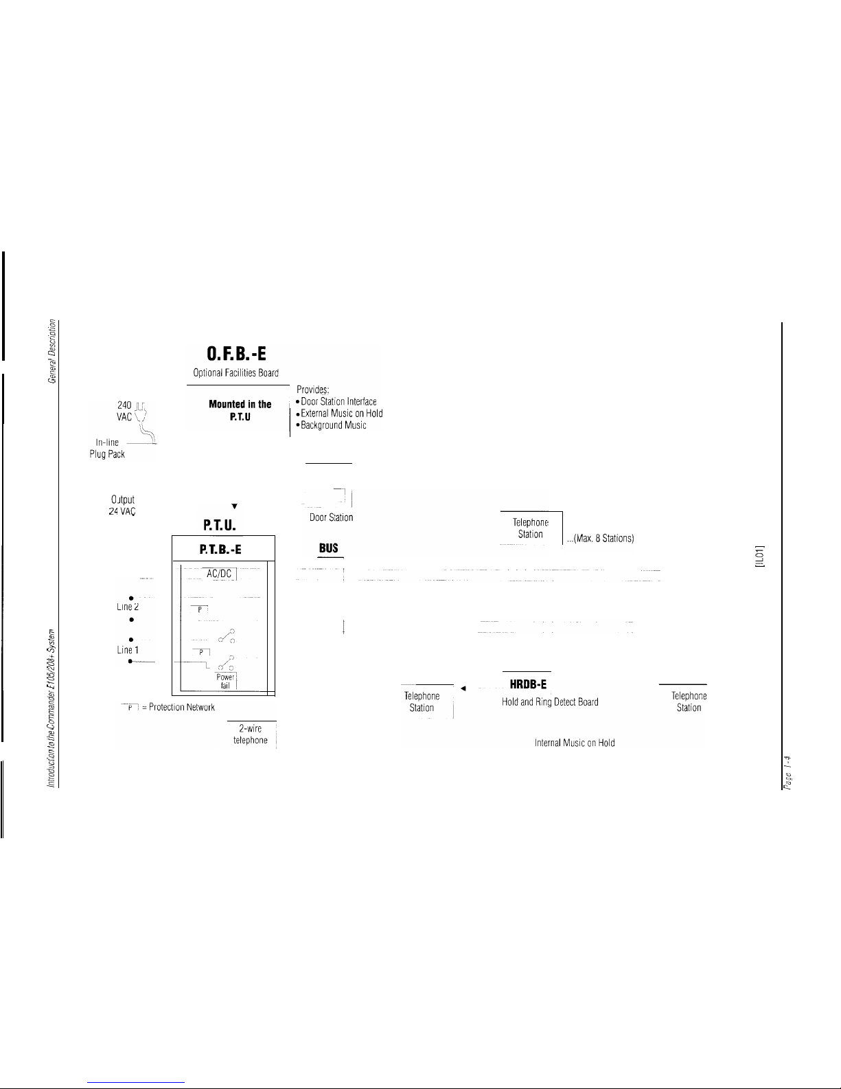
Refer to Illustration 1 - System Block Diagram.
A single-chip microcomputer in each keystation controls all operational
facilities of the Commander
E105/208+
system.
An in-built speaker provides keystation tones.
A RISC microcomputer controls all keypad functions.
The station microcomputer’s program and data are stored in 8K words
of ROM and 2K bits of RAM. They control all keystation and data
communication functions. During a power failure, a supercapacitor
back-up protects abbreviated dialling numbers (stored in RAM). This
back-up also allows keystations to be unplugged and moved at will from
point to point.
Commander E105/20& Installation and Maintenance Manual
Page 1-l
Page 17
Introduction to the Commander E105/20& System
General Description
System Communications
A carrier-sense, multiple-access communications protocol with
frequency-shift keying transmission achieves signalling between
keystations on the system bus.
DIP Switches
Several keystation facilities are individually programmable via“DIP”
switches located in the base of the keystation’s housing.
These include:
.
keystation address
.
master page inclusion
.
STD/IDD access
.
exchange line ring assignment
.
pulse or tone dialling
.
auto pause insertion.
System Master Keystation
Every system installation must include a System Master Keystation. It
contains the Hold and Ring Detect Board (HRDB-E), which provides
all the electronics necessary for:
.
exchange line ring detection
.
line holding
.
internal music on hold.
From a user’s viewpoint, the operation of a system master keystation is
identical to that of a standard keystation.
Power and Termination
Unit
The other major component of the Commander
E105/208+
system is
the Power and Termination Unit (PTU). This compact unit houses the
Power and Terminating Board (PTB-E) and Optional Facilities Board
(OFB-E).
The PTU and OFB-E for the Commander E
105/208+
are the same as
that used on Commander E
105/208.
Dial Pad Programming
Several keystation facilities are individually programmed via the station
dial pad. These programming steps are password protected.
Page l-2
Page 18
General DescriDtion
introduction to
the Commander E105/208+ System
Power and Terminating
Board (PTB-E)
Optional Facilities Board
(OFB-E)
Power Supply
Commander
E105/208t
Installation and Maintenance Manual
Page 1-3
Powerfail
Door Station
The PTB-E provides output terminals for the bus and input terminals for:
.
a maximum of two exchange or PABX lines
.
plug-pack power supply
.
telecommunications reference conductor (if required)
.
power-fail telephone
.
external music source.
This board also supplies system power supply regulation and the system
power-fail relay, as well as exchange line electrical protection.
An OFB-E is installed in the PTU to provide any or all of the following
facilities:
.
Door Station
.
external music on hold
.
background music
Equipped with the same high performance microcomputer as the
keystdtions, the OFB-E contains the required intelligence for bus
communications and control functions for the optional features.
The OFB-E is connected to the PTB-E via a flat cable.
Input power is supplied to the PTB-E via a double-insulated,
mains-
operated, in-line plug-pack.
During a power failure, exchange line calls can still be made and
received at a specially provided two-wire telephone that is automatically
switched across the first incoming exchange pair.
The Door Station is a compact unit incorporating a speaker and
microphone. A Door Station provides two-way communications
between any unsupervised area and a keystation.
Page 19
Introduction
to
the
Commander
E105/208+
System
General
Descriotion
-
System Block Diagram
[IL011
Page
l-4
Page 20
Svstem Features
introduction to
the Commander
E105/208t
System
System
Features
Keystations
Four types of stations are associated with the Commander E
105/208+
system:
.
E105+ Master Keystation
Contains the hold and ring detection circuitry.for the
E105-t
System.
.
E208+
Master Keystation
Contcrins
the hold and ring detection circuitry
for
the
E208+
system.
.
E208+ Standard Keystation
.
Door Station
For use on both
E105+
and
E208+
systems.
NOTE:
Both Commander E
105+
and Commander E208+ Master
Keystations have keys provided for 2 exchange lines. The
E
105+
Master Keystation however differs from the
E208+
in that the
inbuilt
HRDB-E (Hold and Ring Detect Board) is
only equipped to handle 1 exchange line.
Standard Keystations are identical for both size systems.
Visual Indications
Visual indicators on each keystation show the status of:
.
Exchange lines
idle
incoming ring
hU.SY
hold
conference
.
Intercom circuit
free
busy
incoming cull
.
Do Not Disturb
.
Speaker On.
Programmable Facilities
Several options and facilities can be programmed at each keystation via
“DIP” switch settings. The DIP switches are located under the base of
the keystation.A small protective cover must be removed to access the
DIP switches. Further options are programmed via the keystation dial
pad. These options are password protected.
Commander
E105/208t
lnstailation
and
Maintenance
Manuai
Page
1-5
Page 21

Introduction to the Commander E 105/208+
System
System facilities
System Facilities
Incoming Calls
Audible Signalling
Do Not Disturb
Exchange Call Automatic
Answer
Exchange Call Queuing
Flexible Ring Assignment
During a Call
Call Transfer
Conference
Hold - Common
Hold - Recall
Distinctive ring tones from the keystation loudspeaker signal incoming
exchange line, intercom and hold recall calls.
NOTE:
The exchange line ring cadence is internally generated within
the system
anddoes not
track the exchange ring cadence.
When invoked, this facility blocks the audible signals of all incoming
exchange line and intercom calls. Each keystation provides visual
indication of DND.
Each keystation can be programmed to automatically answer incoming
exchange line calls when the handset is lifted.
When Exchange Call Automatic Answer is selected, and more than 1
call is ringing, lifting the handset will answer the oldest call.
Each keystation can be programmed to signal or not
signal
exchange line calls by an audible tone on a per-line basis.
incoming
Allows an exchange line call to be transferred to another keystation after
it has been announced.
Allows the establishment of a conference with one external and two
internal parties or three internal parties.
Places a call on hold for any keystation to retrieve.
When an exchange line call is placed on hold, a reminder ring signal is
activated every 90 seconds at the keystation that initiated the hold
condition.
Page l-6
Page 22
Svstem facilities
Introduction to
the Commander
E105/208t
System
Music-On-Hold
Off-Hook Signalling
PABX Recall
Outgoing Calls
Access Barring
Automatic Pause
Insertion on PABX lines
Decadic to Tone
Signalling
Direct Exchange line
Access
last Number Redial
live Key Working
On-Hook
Dialling/Monitor
Automatically transmits music to a caller on hold. The music may be
generated internally, or provided by an external source. (The Optional
Facilities Board is required for externally provided Music-On-Hold).
Provides a muted audible exchange line signal to a busy keystation when
it receives an incoming exchange line call.
When the system operates behind a PABX, this facility enables access
to the facilities of the host PABX. Only TLB is provided.
Restricts the range of numbers that can be
dialled
on akeystation. Each
keystation can be programmed for one of two classes of Access Barring
via a DIP switch located in the keystation.
Class 1
unrestricted access
Class 2
access restricted to exception table entries plus access to
OOO,OO8,013,016n >
n, 122n > n, 11441 > 11440,
13n >
n,0175,18nn.
Exception Table is 8 entries of 4 digits each.
When using the abbreviated dial and redial facilities on PABX lines, the
system automatically inserts a three-second pause.
After connecting a keystation to a called party on a decadic exchange
line, the dial pad can be used to send further numbers in tone (DTMF)
signalling.
Direct access to exchange lines by any keystation using a single key.
Press [REDIAL] to automatically redial the last number
dialled.
After pressing an exchange line key, the loudspeaker automatically
activates to allow the
dialling
of a number without lifting the handset.
Enables a keystation to originate a call and monitor its progress without
lifting the handset. However, you must use the handset to speak to the
called party.
Commander E105/208+ Installation and Maintenance Manual
Page
1-7
Page 23

Introduction to the Commander E105/208+ System
System
Facilities
Station Abbreviated
Dialling
Station Speed Dialling
Internal Calls
Alternative Point
Answering
Direct Keystation
Selection
Intercom
Intercom Voice/Ring
Signalling
Meet-Me Paging
Paging
Voice Call
By pressing [MEMORY] and then dialling a memory location
(O-9),
each keystation can access up to ten programmed numbers having a
maximum of 19 digits. Each keystation has its own ten-number
memory.
When the handset is lifted or the station is ‘off-hook’, and an exchange
line is selected, up to 8 speed dial keys can be used to select preprogrammed speed dial numbers. These numbers are a subset of those
used for station abbreviated dialling.
Allows any keystation to answer an intercom call directed to another
keystation by pressing [CONF].
Allows single-button access to another keystation by pressing the
required DSS key (1 to 8).
Establishes a private call between any two keystations.
Allows the keystation user to select to make either an intercom signal
call or an intercom voice call. An intercom signal call is when an
intercom ring is sent to the called keystation. An intercom voice call is
when, after a short tone, the caller can speak directly to the called party
through the called station’s
inbuilt
speaker.
In both cases, the called party must lift the handset to speak to the
calling party.
After a paging announcement, the paged person can contact thecalling
party by pressing [PAGE] on any keystation.
Allows paging of all other keystations through theirloudspeakers from
any keystation. Individual keystations can be programmed to bar the
reception of a page announcement. (Note that keystations programmed
not to receive page calls are also excluded from receiving Door Station
chimes).
Allows a keystation user to call any keystation and speakdirectly
through the speaker of the called keystation.
Page
1-6
Page 24
System
Facilities
Introduction to the Commander
E105/208t
System
Door Station
Portability
Powerfail Operation
Power Failure Memory
Retention
Keystation Directory
Wall-Mounting Bracket
Miscellaneous
Background Music
(Optional)
Call Progress Tones
Confidence Tone
Provides two-way communication between an unsupervised areaand
any keystation on the system. (Note that keystations programmed not
to receive paging calls are also excluded from receiving door station
chimes.) (The Optional Facilities Board is required to provide the Door
Station facility.)
Allows movement of keystations to other sockets in the systemwhile
still retaining their identity and abbreviated dialling information.
During a power failure, exchange line calls can be made and received at
a specially provided two-wire telephone.
Retains the keystation’s abbreviated dialling memory during an extended
power failure for a minimum of 24 hours.
A directory label designed to adhere to the face of each keystation is
provided for the recording of extension numbers and abbreviated dial
numbers.
Enables keys stations to be wall-mounted.
Music supplied from an external source can be broadcast through
keystation loudspeakers, and turned on and off at each keystation as
required. The music automatically turns off when a call is in progress.
The Optional Facilities Board and an external music source (including a
Telstra approved Line Isolation Unit) are required to provide this facility.
Tones indicate the call
status to
the user.
A low-level, audible tone indicates that a key press is registered. The
user enables or disables this facility.
Commander
E105/208t
installation and Maintenance Manual
Page I-9
Page 25

Introduction to the Commander
E105/208t
System
System
Facilities
Headset Mode
A keystation handset may be replaced by a suitable Austel permitted
headset. When connected and activated, the [SPKR] key is used to
perform the off-hook function. Headset mode is protected against
activation and deactivation by a two-key activation sequence.
Secrecy
Visual Indication
All external and internal calls provide secrecy.
Visual display is provided at each keystation to indicate:
.
all incoming exchange line calls
.
exchange line held condition
.
exchange line in-use condition
.
exchange line in conference
.
other conditions such as intercom line status, Do Not Disturb,
Speaker On and Headset Mode selected.
~
Page l-10
Page 26

Chapter Two
Power and Termination Unit
L
Page 27

Chapter Two
Power and Termination Unit
Table of Contents
Introduction
......................................................................................................
2-1
General Description
............................................................................................
2-1
Power and Terminating Board
.........................................................................................
2-2
Optional Facilities Board (Optional)
.................................................................................
2-2
Circuit Blocks . Power and Terminating Board
...........................................................
2-3
Transformer
....................................................................................................................
2-3
Power Supply
.................................................................................................................
2-3
Electronic Choke
............................................................................................................
2-3
Powerfail
........................................................................................................................
2-3
Exchange Line Protection
................................................................................................
2-3
System Bus
.....................................................................................................................
2-3
Circuit Blocks.Optional Facilities Board
.................................................................
2-5
Microcomputer Unit (MCU)
...........................................................................................
2-5
Data Transmit and Receive
..............................................................................................
2-5
Door Station Interface
.....................................................................................................
2-5
External Music Source Interface
......................................................................................
2-5
Chapter Two
Page 28

I -
Introduction
Chapter Two
Power and Termination Unit
This chapter provides a general description of the Power and
Termination Unit and its two major components: the Power and
Terminating Board (PTB-E) and Optional Facilities Board (OFB-E). It
also includes PTB-E and OFB-E circuit block diagrams and a
description of all circuit blocks depicted in both diagrams.
General
Description
The Power and Termination Unit (PTU) houses the Power and
Terminating Board (PTB-E) and Optional Facilities Board (OFB-E).
Refer to
Illustration 2 - PTU.
The PTU is a wall-mounted plastic housing that contains:
.
exchange line terminations
.
system bus terminations
.
line protection circuitry
.
power-fail relay
.
system power regulation and reticulation.
An in-line, mains-operated plug-pack, supplied as part of the PTU,
supplies the
PTU’s
AC power.
@lstra
PI1 0 -
COMMANDER-E
PTU
[IL021
Commander E105/208+ Installation and Maintenance Manual Page 2-l
Page 29

Power and Termination
Unit
General
Description
Power and Terminating
Board
Board Code - PTB-E
Location - PTU Base
Description - The PTB-E provides:
.
the system terminal strip
Used to terminate: incoming exchange lines; the system bus;
the power-fail station and external background music inputs.
.
power supply circuitry
.
exchange line protection.
Optional Facilities Board
(Optional)
Board Code - OFB-E
Location - PTU Cover
Board Description - An OFB-E is installed in the PTU when any of
the following optional facilities are required:
.
Door Station
.
external music-on-hold
.
background music
The OFB-E uses the same microcomputer as the keystations. It
contains: the intelligence required for bus communications, the control
features necessary for the optional facilities and the Door Station input
terminals. The OFB-E connects to the PTB-E via a flat cable.
Page 30
I -
Circuit
Blocks - Power and Terminating Board
Power and Termination Unit
Circuit Blocks - Power and Terminating Board
Refer to
Illustration 3 - PTB-E Circuit Block Diagram.
Transformer
A double-insulated plug-pack that delivers 24V AC Nom. to the power
supply.
Power Supply
Delivers DC voltages for the system bus communications pair.
Electronic Choke
Decouples the Audio and Frequency Shift Keying signals from the DC
feed.
Powerfail
When power fails, a relay releases that switches each exchange line pair
in the system to a standard two-wire telephone.
Exchange line Protection
Metal Oxide Varistors
(MOV’s)
isolate exchange line pairs from high
voltage surges on the exchange lines.
System Bus
The system bus consists of a pair of wires for each exchange line (the
Commander E
105+
system contains one spare pair) and a single pair
for the following:
.
system communication
.
power reticulation
.
intercom
.
paging
.
conference calls.
Commander
E105/208t
Installation and Maintenance Manual
Page 2-3
Page 31

Power and Termination Unit
Circuit
Blocks - Power and Terminating Board
240V
AC
Exchange lines
Powerfail ports
Plug Pack
, Transformer
Powerfail
Power
SUPPiY
Electronic
Choke
~ protection
System Bus
1 ’
Terminal Strip
b
I
To keystations
PTB-E Circuit Block Diagram
[IL031
Page 2-4
Page 32

Ciicuit Hocks -
Ootional Facilities Board
Power and Term/nation Unit
Circuit Blocks - Optional
Facilities
Board
Refer to
Illustration 4 - OFB-E Circuit Block Diagram.
Microcomputer Unit
NW
The OFB-E Microcomputer Unit controls:
.
Door Station interface
.
external music source interface
It works in conjunction with the keystation microcomputer to control the
systems’ optional facilities.
NOTE:
PABX Earth Recall is not available on the Commander
E
105/208+.
Data Transmit and
Receive
Converts data transmitted on the bus pair into logic levels for the
Microcomputer Unit.
Door Station Interface
Provides circuitry to connect a single Door Station to the system.
Intercom transmission between the door and keystation is via the bus
intercommunication channel.
External Music Source
Interface
Provides circuitry for the connection of an external music source to the
system. Background music and music-on-hold are relayed to the
keystations via the bus intercommunicationchannel.
Commander
E105/20&
Installation and Maintenance Manual
Page 2-5
Page 33

Power and Termination Unit
Circuit
Blocks - Optional Facilities Board
Bus
<
I
Door
<
Station
External
Music
/
Data
>I
Transit
I
and Receive
I
\
>I
<
<
Exchange
Lines
Earth
OFB-E Circuit Block Diagram
[IL041
>I
MCU
Page 2-6
Page 34

-
L
Chapter Three
Keystations
Page 35

Chapter
Three
Keystations
Table of Contents
Introduction
......................................................................................................
3-l
General Description
.............................................................................
.
..............
3-1
Keystation Main Board
...................................................................................................
3-2
Hold and Ring Detect Board
...........................................................................................
3-2
Keypad Assembly
...........................................................................................................
3 -2
Circuit Blocks
..........................................
.
..............................
.
...........
.
..............
3-3
Microcomputer Unit Circuit (MCU Circuit)
.....
................................................................
3-3
Keypad RISC Processor
.......................................................................................
3-3
Memory
................................................................................................................
3-3
Memory Back-Up Circuit
......................................................................................
3-3
Reset..
...................................................................................................................
3-3
Power Supply
.................................................................................................................
3-3
Isolation Transformer
.......................................................................................................
3-3
Data Transmit and Receive
..............................................................................................
3-4
Speech Circuit
................................................................................................................
3-4
Tone Generator
...............................................................................................................
3 -4
Audio Selector
................................................................................................................
3 -4
Audio Amplifier
...............................................................................................................
3 -4
Line Access Circuit
.........................................................................................................
3-4
HRDB-E Board (In Master Keystation)
..........................................................................
3-4
Line-Hold Circuit
...................................................................................................
3 -4
Ring Detect Circuit
.................................................................................................
3-4
Chapter Three
Page 36

Chapter Three
Keystations
I
Introduction
This chapter provides a general description of the keystation and its two
major printed circuit boards.
It then provides descriptions of each
keystation circuit block and a circuit block diagram.
General
Description
There are 3 types of system keystations.
.
E
105+
Master Keystation
Contains the hold and ring detectiorl circuitry
for
the
Commander El
05+
system.
.
E208+
Master Station
Contains the hold nnd ring detection circuitry for the
Commcmder E208-b
systtm.
.
E208+ Standard Keystation
NOTE:
Both Commander E
105+
and Commander E208+ Master
Keystations have keys provided for 2 exchange lines. The
E
105+
Master Keystation however differs from the
E208+
in that the
inbuilt
HRDB-E (Hold and Ring Detect Board)
and the Control Board are only equipped to handle 1
exchange line.
Standard Keystations are identical for both size systems.
All keystations contain a telephone network that includes:
.
a handset
.
a dial keypad incorporating a RISC processor.
.
non-locking function keys
.
status Light Emitting Diodes (LEDs) (housed in keys)
.
a speaker
.
volume control.
The Master Keystations also carry a line hold and ring detection
HRDB-E circuit board.
Refer to Illustration 5 -
E105+
and
E208+
Keystation.
I
,-
Commander
E105/208t
installation and Maintenance Manual
Page 3-I
Page 37

Keystations
General
Description
Keystation Main Board
Hold and Ring Detect
Board
Keypad Assembly
Board Code - KSB-E-A (Keystation Main Board)
Location - Keystation
Board Description - This board contains a high-performance, single
CMOSchip microcomputer and associated circuitry. It controls all
keystation, system and data communications functions and contains the:
.
keystation power supply
.
speech and audio circuitry
.
data transrnit and receive circuitry
.
line control circuitry.
Board Code - HRDB-E
Location - Master Keystation
Board Description - This board contains circuitry that controls system
ring detection and line holding functions. It also accommodates the
internal music-on-hold feature. This board differs between Commander
E105+ and Commander E208+ systems.
Location - Keystation
Description - This assembly generates
dialling
and system function
signals. It consists of a rubber keypad and printed board assembly
connected to the keystation main board via a ribbon connector. The
assembly is controlled by a RISC processor. This processor also
handles keypad interfacing with the keystation Main Board.
Commander
E105+
and
E208+
Keystation
[IL051
Page 3-2
Page 38

Circuit Blocks
Keystations
Circuit
Blocks
Microcomputer Unit
Circuit
(Mhl
Circuit)
Keypad RISC Processor
_ -
Memory
Memory Back-Up Circuit
Reset
Power Supply
Isolation Transformer
Refer to
Illustration 6 - Keystation Circuit Block Diagram.
Controls keystation operation. The MCU works in conjunction with
other keystations (and the
OFF&E,
if installed) to control the system
operation.
Specifically, the keystation central microcomputer controls the:
.
exchange line interface
.
keystation communications and operation
.
intercom keystation interconnection
.
connection of signal tones to the keystation
.
system option programming.
This process or provides an intelligent interface between the keypad and
the station Microcontroller unit. It provides mapping for all ‘intelligent
keys’, such as DSS/Speed Dial keys and
Centel@
functions keys.
Keystation memory consists of 8K words of ROM (10 bits per word)
and 5 12 words of RAM (4 bits per word).The microcomputer uses the
Random Access Memory (RAM) to store abbreviated dialling codes.
The microcomputer uses Read Only Memory (ROM) to store the
keystation’s operating program.
During brief power down periods, the memory back-up circuitprotects
the abbreviated numbers stored in RAM. This circuit consists of a
supercapacitor (charged ready for use under normal keystation
operating conditions) and associated control circuitry.
When low voltages are detected, the reset circuit transmits an interrupt
signal to the Microcomputer Unit (MCU) and generates a reset pulse
when power is restored.
A DC-DC converter that steps down and isolates bus voltages to
supply the keystation circuit requirements.
Isolates keystation circuitry from the bus.
Commander E105/208+ Installation and Maintenance Manual
Page 3-3
Page 39

Keystations
Circuit Blocks
Data Transmit and
Receive
Converts data transmitted on the bus power pair into logic levels, then
directs the signal to the keystation MCU serial port
signalling
interface.
Speech Circuit
Provides an interface for the telephone network intercom channel,
transmission circuit and handset.
Tone Generator
Provides the DTMF tone and all audible tones emitted by the
keystation.
Audio Selector
This circuit couples either:
.
audio signals from the speech circuit to
the
audio amplifier when
connected to either the telephone line or the bus,
or
.
audible tones from
the
tone generator to the audio amplilier when
required for either audible tones in the earpiece or transmission of
DTMF signals.
Audio Amplifier
Under control of the audio selector, the audio amplifier drives the
keystation speaker. Line access connects lines to the speech circuit by
an MCU-controlled relay.
line Access Circuit
Provides an interface between the speech circuit and either of the
exchange lines. It also provides a solid-state switch fordialling
purposes.
HRDB-E Board (In Master
Keystation)
The HRDB-E board is contained in the system Master Keystation.
Line-Hold Circuit
Provides line-holding control at the master keystation in the system.
All other keystations in the system can assert line-holding control. They
can also transmit and receive the line hold on/off codes (received by the
master keystation) along the bus communications channel (service a and
service b) .
Ring Detect Circuit
Provides ring detection for the master keystation only. All other
keystations in the system respond to “line ringing” and “line terminated”
codes transmitted by the master keystation along the bus
communications channel.
Page 3-4
Page 40

Circuit
Blocks
Keystations
I
-
Keystation Circuit Block Diagram
[IL061
Commander
E105/20&
Installation
and
Maintenance
Manual
Page
3-5
Page 41

Chapter Four
Hardware Installation
Page 42

Chapter Four
Hardware
Installation
Table of Contents
Introduction ...................................................................................................... 4-1
Component Safety Precautions.....................................................
. ........................
4-l
Installation Checklist ..........................................................................................
4-2
Installation Procedures .......................................................................................
4-3
Sales Form Completion/ Equipment Ordering
.................................................................. 4-3
Locate and Mount Equipment
..........................................................................................
4-3
Customer Responsibilities
...................................................................................... .4-3
Power and Termination Unit (PTU)
......................................................................
.4-5
Power Supply Plug-Pack
......................................................................................
.4-8
Sale/Rental Window..
............................................................................................. 4-8
Wall Mounting Keystations..
..................................................................................
.4-V
Door Station
........................................................................................................
4-
11
Optional Facilities Board Installation (OFB-E)
...............................................................4- 1 1
Connect and Terminate Cables
......................................................................................
4- 12
Cabling Limitations
..............................................................................................
.4-
13
Power and Termination Unit (PTU) Terminations
.................................................
.4-
14
Power Supply Plug- Pack
...................................................................................
.4-
14
Exchange Lines
...................................................................................................
.4-
14
Keystations..
.......................................................................................................
.4- 15
Modular Socket Termination
...............................................................................
.4-
15
Door Station
.......................................................................................................
.4-
16
Power-Fail Telephone
.........................................................................................
.4-
17
Internal Music-On-Hold..
....................................................................................
.4-
17
External Music Source
........................................................................................
.4-
17
Protective Earth
............................................................................................................
4- 17
General Procedure ............................................................................................. 4-18
Power Up
.....................................................................................................................
4- 18
Check Cabling
..............................................................................................................
4-
I8
PowerDown ................................................................................................................ 4-18
Plug in Keystations
........................................................................................................
4- 18
Keystation Self Test
......................................................................................................
4- 18
Test Mode Entry
...........................................................................................................
4- 18
Chapter
Four
Page 43

LED Tests
.....................................................................................................................
4-19
Keyboard Tests
..................................................................................................
.4-
19
Audio Circuit Test
...............................................................................................
.4-
19
Test Failure
..........................................................................................................
4-20
Test Mode Exit
....................................................................................................
4-20
programming
.................................................................................................................
4-20
Defective Equipment
.....................................................................................................
4-20
I -
I
Commander
E105/208t
Installation and Maintenance Manual
Chapter Four
Page 44

Chapter Four
Hardware Installation
Introduction
This chapter describes the procedures for installing the Commander
E105/208+ system hardware.
It begins with an Installation Checklist that summarises all the hardware
installation procedures. Each point in the checklist is then covered in
detail, with full installation procedures and additional relevant
information. Where appropriate, an illustration and reference are
provided.
Component
Safety Precautions
Commander
E105/208+
equipment contains a considerable number of
MOS and other static-sensitive components. To reduce the incidence
of premature failure due to static discharge, ensure that you take the
following precautions.
.
Always discharge static from yourself before you handle a printed
board assembly (PBA)
.
Always disconnect power before handling or installing
PBAs
.
Always handle PBAs by the edges
.
Never touch PBA tracks or edge connectors. Contaminents
introduced by fingers can cause corrosion and high-resistance
connections.
.
Never touch components. They are physically delicate and finger
pressure can fracture (but not necessarily break) components
leads.
.
Never attempt to repair power plug-packs in the field. They are
powered from the 240V mains supply and contain hazardous
voltages.
Bus cabling is polarity-sensitive. It is essential that correct polarity is
maintained. Be careful when checking voltages on cabling.
BuswREcBl.omMoMllARsocKET
BuswmE
BESIBBATION
Green
1
L2b
Black
2
Service b (-50V)
Blue
3
Llb
White
4
Lla
Red
5
Service a (OV)
Orange
6
- L2a
Table 1 - Bus Cabling
Commander
E105/208t
Installation and Maintenance Manual
Page
4-1
Page 45

Hardware
Installation
installation Checklist
Installation Checklist
Use the following checklist in conjunction with the detailed procedures
that follow to ensure that you install the Commander E
105/208+
system
correctly.
.
Order the necessary equipment using the Sales Form
.
Locate and mount equipment
power and termination unit
power supply plug-pack
keystations
Door Station
power-fail telephone
.
Connect and terminate cables
system bus
power supply plug-pack
exchange lines
keystations
modular sockets
Door Station
power-fail telephone
external music-on-hold
.
Connect OFB-E and Telstra reference conductor (if required)
.
Power up
.
Check cabling
.
Power down
.
Plug in keystations
.
Program the system (refer to Chapter Five)
.
Power up
.
Wait 10 seconds for the system to initialise
.
Test the system (refer to Chapter Six)
IMPORTANT
.
Designate sale or rental keystation
.
Complete installation dates and warranty labels on equipment
.
Complete site records
.
Leave system user guide with system administrator.
Page 4-2
Page 46

Installation Procedures
Hardware
tnstallation
Installation
Procedures
Sales Form Completion/
Equipment Ordering
The Telephone Order for any S.B.S. must be accompanied by an
S.B.S. System Order. Sales staff, after consultation with the customer,
must complete the S.B.S. System Order.
Use the information provided in the System Order form to order the
various items required for the installation, and to find the required
programming
information.
Forward three copies of the System Order to the installation area along
with the Telephone Order.
On completion of the installation, any variations to the System Order
must be noted on each copy of the order.
Keep one copy of the System Order with the equipment as a record of
the particular installation. Return the remaining two copies to the local
Telstra Business
Offke.
Refer to
Illustration 7 - System Order Form.
locate and Mount
Equipment
Customer Responsibilities
The customer is responsible for providing:
.
satisfactory lighting for installation and maintenance activities
.
a single-phase, correctly earthed,
220-25OV, lOA, 50Hz
AC
general-purpose power outlet within one metre of the equipment.
Commander E105/208~ Installation and Maintenance Manual
Page 4-3
Page 47

Hardware
Installation
Installation Procedures
Commander E105/208+ System Order Form
celstru
System
Order No(Servm Plus)
I I I
Cuslomer’s Name
I I 1 [--I I--I 1 1 1 j-1 j 1 1 1 1 1 / [ 1 1 1 1 1 j [ 1 1 1 1
.-
Type of Payment
(4)
Address
llllllllllllllllllllllllllll
JLeaSe
Town or Suburb Post Code
/ LA Standard Rental
u Outrrght Purchase
u Short Term Rental
Nature 01 Business
LLLLl
I I I I I I I I I I I I I I I I I I I I I I I I I I
IL1
Temporary Rental
u Other
Customer Contact Telephone
I
Sales Contact
Telephone
Division
(J)
Comm ;J
C&Gii
Cons U
Install Req Date
App’n Date
Date Order Issued
Date Completed
STD Code Service No
PABX Extn
D DMMY
YDDMMYY
D DMMY
YDDMMYY
1 j 1 / [ 11 1 j 1 I ]lfollPABX[ 11 11 1 I I j 1 I I [ I 11 11 / 1 I j I I 11
1 I I I I
11
Programmable Options
SW1 Station Address
SW1 Station Address
Keyboard
sw2:
1-
4
5
:
a
Programming
STNl
All
Call Page
Ring Line 2
j
Dial Type1 Auto
Pause
Insert
Auto Answer
1 I I I
I
7
/ I
3 !
I
d
I
I
I I
Exception Table
i
1=
Enabled
1=
Enabled
1=
Enabled
1=
Enabled
1=
Decadic
1=
Enabled
1=
Enabled
0 = Disabled
(1)
~
0 =
Disabled 0 =
Disabled
0 = Disabled
0 =
DTMF0 =
Disabled
0 =
Disabled
0
(1) (1)
(1)
(1)
(0)
(0)
Switch
If ‘0’ go to
Positions
Exception Table
Switch
Positions
If ‘0’ go to
Exception Table
Exchange Line Connections
t:_:
Exchange Line
Tie = Non PABX
= Non PABX
Tick II
Required
1 Service Order No
Serral/ltem
546/203
External Mus,c Source 1 Permit No
I
FM-00345-I701
1520
System Order Form
[IL071
Page 4-4
Page 48

installation Procedures
Hardware
Installation
Power and Termination
Unit (PTU)
Mounting Limitations
Ensure that you install equipment in a position allowing adequate access
for maintenance activities. The space requirements for wall-mounted
equipment are:
.
no less than 300mtn clear wall space on each side
.
no less than
38Omm
and no more than
1.8m
from the floor
.
no less than one metre of clear floor space in front of the
equipment.
Refer to
Illustration 8 - Limitations to Wall Mounting.
NOTE:
Initial systems are equipped with a conventional non-in-line
plug-pack. You may be unable to plug this type of
plug-
pack into some power points with limited clearance, such
as a ‘low-line GPO’ on
ducted
skirting.
Accordingly, locate an appropriate 240V AC GPO to
accommodate the plug-pack dimensions. Refer to
Illustration 9 - Plug-Pack Dimensions.
If such an outlet cannot be located, a short 240V AC
extension cord or similar should be used to enable
installation.
I
b
Maximum clearance of
300mm on each side
II
PTU
I
380mm min
Plug pack may be located as close to power outlet
as
required
within one metre of the
PTU
.
I
1.8m
max
limitations To Wall Mounting
[IL081
Comma,nder E105/20& lnstallafion and Maintenance Manual
Page 4-5
Page 49

Hardware
Installation
Installation Procedures
Plug-Pack Dimensions
[IL091
Installation Procedure
Mount the PTU as follows:
Unclip the cover from the base by using a screwdriver in the slot
in the top or bottom of the unit
Disconnect the LED flying lead from the PTB-E
Attach the base to the wall using three screws. Do not
overtighten screws.
Remove the cable entry tab at the bottom or top of the base by
pushing fnmly downwards
You may also bring cubles in from the back of the PTU
through the centre hole.
Pass the cables through the entry
Place wires in screw terminals and tighten
Attach LED flying lead to PTB-E
Replace PTU cover on base.
Refer
toIllustration 10 - Power and Termination Unit
Dimensions
and
Illustration 11 - Power and Termination
Unit Mounting.
Page 4-6
Page 50

I -
Installation Procedures
Hardware
Installation
I-
185mm
celstra
ON 0 -
COMMANDER-E
Power and Termination Unit Dimensions
HL101
Cableentry
push-through
COMUANOER -
Cableentry
..t
push-throughpush-through
-=T3
0
I - 120mm
4
1 OOmm
C
4
L-
6Omm
162mm
t
Power and Termination Unit Mounting
[IL111
Commander
E105/20&
Installation and Maintenance Manual
Page 4-7
Page 51

Hardware
Installation
Installation Procedures
Power Supply Plug-Pack
To mount the power supply plug-pack:
.
Locate the customer supplied, 240V AC mains supply outlet
(within one metre of the PTU)
.
Ensure that the outlet is switched OFF
.
Attach the plug-pack to the wall using the bracket supplied
.
Plug power pack supply into mains outlet.
Sale/Rental Window
Refer to the System Order form to determine if the system is sold or
rented. Then, before installing each keystation, identify it as follows:
.
Remove the latched cover on the keystation base
.
For a sold system, pierce the window next to S
.
For a rented system, pierce the window next to R
.
Only pierce one window on each keystation.
.
Replace the cover.
Refer to
Illustration 12 - Sale/Rental Identifying Window.
0
0
Sale/Rental
Identifying Window
[IL121
Page 4-8
Page 52

Installation Procedures
Hardware
Installation
Wall Mounting Keystations
To mount a keystation on the wall:
-
.
.
Obtain a Wall Mounting Kit (WMK-E)
Push out the handset rest from the centre of the wall mounting
bracket and insert it in the hole under the earpiece in the handset
Refer to Illustration 13 - Installing The Handset Rest.
Remove and discard the modular socket cover and locate the
modular socket inside the wall bracket
Remove the centre cut-out of the wall mounting bracket
Attach the wall mounting bracket to the wall using four screws.
Do not overtighten the screws.
Refer to
Illustration 14 - Keystation Wall Mounting
Dimensions.
Connect the short line cord between the socket and the top of the
key station
Clip the keystation into the wall mounting bracket.
Refer to
Illustration 15 - Wall Mounting the Keystation.
Installing The Handset Rest
[IL131
Commander E105/208+ Installation and Maintenance Manual
Page 4-9
Page 53

Hardware
installation
installation Procedures
I
i
154mm
Keystation Wall Mounting Dimensions
[IL1
41
Wall Mounting the Keystation
[IL151
Page 4-10
Page 54

Installation Procedures
Hardware
Installation
Door Station
To mount a Door Station:
.
-
Remove the base of the Door Station
.
Attach the base to the wall using two screws. Do not
overtighten the screws.
Refer to
Illustration 16 - Wall Mounting Dimensions For
Door Stations.
.
Pass the cable through the base using the cable entry at the top of
the base
.
Attach the Door Station to the base.
0
Door Station
Mounting Holes
4
90 mm
Wail Mounting Dimensions For Door Stations
[IL161
Optional Facilities Board
When the OFB-E is installed in the PTU, it extends the system facilities
Installation (DFB-E)
by providing:
.
a Door Station interface
.
an external music-on-hold interface
.
a background music interface
If any of these facilities are required, the OFB-E must be installed in the
PTU.
To install the OFB-E:
.
Mount the OFB-E in the PTU cover
.
Secure it in place with the four screws provided. Do not
overtighten the screws.
.
Connect the cable from the OFB-E to the PTB-E.
.
Select link for external music (EXT) or internal music (INT) or no
music on hold (See page 5-8 for more details).
Commander E105/208+ Installation and Maintenance Manual
Page
4-11
Page 55

Hardware
Installation
Installation Procedures
Connect and Terminate
Cables
Power and Terminating Unit
Exchange or
PABX Lines
Powerfai I
telephone
External
Music Source
Door
Station
u--- 10
. . . ..0000..1
q
121
!W
l2w
.
T
4w
I SW
L
Line
Isolation
Unit
Commander
E105/208+
Cabling Scheme
[IL171
Page 4-12
Page 56

Installation Procedures
Hardware
installation
Cabling limitations
-
1’
Station
Branch 1
Total = 975m
/ Stat/on / [ Sta/ion 1
1
300m
4
The general rules for determining the allowable bus lengths are:
.
The overall bus length must not exceed 500 metres
.
The total distance of all individual keystations in any one branch
emanating from the
FTU
must not exceed 1000 metres (1 km).
Refer to Illustration 18 - Bus Length, and Illustration 19
-
Example of Allowable Keystation Distances.
Station
I
I
PTU
/
Station
I
L--
1 L S,Ion _I
500 Metres Maximum
Bus
Length
[IL1
81
Branch 2
Total = 500m
I
I
I
I
i
( Stay
on 1 /
Station )
,
max
,
Station
1 j Statign ] j Statipn j L
Statipn
1
:
‘,
$OOm
L!i
50m 3
:+
225m
b
PTU
1OOm
I
Y
250m 150m
,:
200m
k
;
Total Bus Length = 500m
Example of Allowable Keystation Distances
[IL191
NOTE 1:
‘Star’ wiring is acceptable provided the above two general
rules are followed.
NOTE
2: A maximum of eight keystations can be connected to a
branch.
Refer to
Illustration 20 - Example of Unacceptable Cabling
Scheme.
The overall bus length is acceptable at 500m.
However, the individual lengths of branch 2 add up to
1140m.
This exceeds the
1OOOm
limit per branch, and therefore makes
the cabling scheme unacceptable.
Commander
E105/208t
Installation and Maintenance Manual
Page 4-13
Page 57

Hardware
installation
Installation Procedures
If cabled this way, the system would not function properly. In this case,
the PTU should have been located as close as possible to the group of
three keystations to create an acceptable overall length.
Branch1
Total= 150m (Acceptable)
Branch 2
Total
=1140m
(Not acceptable)
Station
4
4
Power and Termination
Unit (PTU) Terminations
Terminate the bus on the PTB-E in the PTU. Refer to
Power and Termination Unit Terminations.
Illustration 21
-
Jl
--~I
12 3
3
0
c>
(1
Lla Llb
L2a
J2
L2b
Bm2 Bm2
.
-
/
Background
To Plug Pack
Lines in
PFl PFl
Music Source/
PF2 PF2
POWerfail External
Powerfail
telephone Music Source telephone
Bla Blb
B2a B2b
VB-
VB+
Stat,ion 1
~ Station ~ Station j Station
J
I
450m b
PTU
.360m,
100m
b
L
380m
b
4
400m
b
Total Bus Length = 500m
Example Of Unacceptable Cabling Scheme
[IL201
White Blue Orange Green Black Red
\
-
4
System Bus
Power and Termination Unit Terminations
[IL211
Power Supply Plug- Pack
To connect the power supply plug-pack to the Power andTermination
Unit:
.
Terminate on the input screw terminals 53 1 and 53 2.
NOTE:
As this is an AC output, it is not polarity-dependent.
Exchange lines
To terminate incoming exchange lines:
.
Terminate on the PTU on the input screw terminals 52 1 and 2
(line
I),
and 52 3 and 4 (line 2).
Page 4-14
Page 58

lnstaiiation Procedures
Hardware
installation
Keystations
To cable and terminate the keystations:
.
Refer to
Table 2 - Keystation Bus Cabling Terminations
.
After cabling the bus, ensure it is properly terminated and that the
polarity is correct.
Ensure the system is cabled correctly. !f it is incorrect, the
equipment will not operate.
It is not important in which order the keystations are connected.
However, it is highly recommended that the master keystation be
designated extension 1. This simplifies identification for maintenance
purposes.
NOTE:
Terminate the keystations on the modular sockets. Refer to
the section - Modular Socket Termination
below.
PTU TERMINALS
.I211
J2 12
J213
12
14
J2 15
J216
Bla
1
White
BUS WIRE
DESTINATION
WRE
COLDUR
MODULAR SOCKET
Table 2 - Keystation Bus Cabling Terminations
Modular Socket
Termination
An MS-E-SMK modular socket is a surface-mounted Krone
termination.
To terminate the MS-E-SMK:
.
Mount the base and socket PBA assembly
.
Cut and strip cable sheath to expose 30mm of conductors
.
Lay the appropriate colour conductors across the required
terminals and terminate using the standard Krone terminating tool
Refer to Illustration 22 - Modular Socket (KRONE Type).
.
Snap-fit the cover to the socket and base.
NOTE:
Where termination of a second cable is required, repeat the
second and third steps above.
Commander E105/208+ Installation and Maintenance Manual
Page 4-15
Page 59

Hardware
Installation
Installation Procedures
1
Green
L2b
2
Black
Service b
3
Blue
Llb
4
White
Lla
5
Red
Service a
6
Orange
L2a
Modular Socket (KRONE Type)
[IL221
Door Station
To connect a Door Station to the PTU:
.
Terminate the two pairs at the Door Station
.
Terminate the two pairs on the OFB-E terminal strip
52
Refer to
Table 3 - Door Station Terminations.
WIRE
WIRE
COLOUR
DESlGNATlON
DESW;NATION
DOOR
STATlON
OFB-E TERMINALS
DR+ Red
DR+
J2 1
DR-
Black
DR-
J2 2
DRA
Blue
DRA
J2 3
DRC
White
DRC
J24
Table 3 - Door Station Terminations
Power-Fail Telephone
To cable and terminate a standard two-wire telephone for apower-fail
telephone:
.
Run the telephone cable directly to the PTU
.
Connect the cable on terminals 52 5 and 52 6, or 52 9 and 52 10,
on the PTB-E as required.
Page 60

installation Procedures
Hardware
Installation
Internal Music-On-Hold
Internal music-on-hold is a standard feature of the Commander
E105/
208+ system. You can disable it on any line if specifically requested by
the customer.
To disable internal music-on-hold:
External Music Source
.
Locate and remove or park jumper links 53 (line 1) and 54 (line
2) on the HRDB-E board in the master keystation. Refer to
Illustration
31-
Program - Internal, External, and No
Music-On-Hold,
page 5-9.
When the customer requires external music-on-hold orbackground
music, ensure that you install the OFB-E in the PTU to provide the
external music source interface.
To connect an external music source:
.
Terminate the external music inputs (via the Telstra approved
isolation unit) to terminals 52 7 and 52 8 in the PTU
.
Locate jumpers 53 (line 1) and 54 (line2) on the HRDB-E in the
Master Keystation
.
Move jumper link 53 from pins 1 and 2 to pins 2 and 3
.
Move jumper link 54 from pins 1 and 2 to pins 2 and 3.
NOTE:
For external music sources and external paging devices,
relay isolation must be in accordance with Telstra
Specification 1364. The device must be:
.
Telstra authorised apparatus only
.
Authorised specifically for use with a Commander
System.
Protective Earth
This Commander System no longer requires the mandatory termination
of a Telecommunications Reference Conductor (TRC) for high voltage
surge protection.
NOTE:
In lightning-prone areas, protect the exchange lines at their
point of entry or distribution in accordance with TPH
0265N0 “Lightning Protection at Customers’ Premises”
and TPH 02 16 “LSA Plus Terminating System”.
Commander
E105/208t
Installation and Maintenance Manual
Page 4-17
Page 61

Hardware Installation
General Procedures
General
Procedure
Power Up
To power up the Commander E
105/208+
PTU:
.
Ensure the system is cabled and terminated correctly
.
Ensure all printed circuit boards are set up and installed correctly
.
Switch on power at the plug-pack GPO.
Check Cabling
Before installing the keystations, measure the voltage at the modular
sockets to ensure that the cabling is correct.
Table 4 - Keystation Voltages
Power Down
To avoid possible damage to keystations, power down the system
before they are connected.
.
Switch off power at plug-pack GPO.
Plug in Keystations
After testing all sockets to ensure the cabling is correct, plug in all
keystations and terminate the Door Station (if required).
Keystation Self Test
In Commander E
105/208+
systems, a self test routine is incorporated in
the keystation software to assist with theirinstallation and maintenance.
The self test covers:
.
speaker
.
tone generator
.
LEDs and keypad operation.
The self test should be performed on all keystations after they are
plugged in.
Test Mode Entry
To place the keystation in Test Mode:
.
Enter the password
The password is:
In1
[71[91 bl
where [n] is the keystation address. Therefore, the password
for keystation 3 is ‘3793
‘.
Page 4-18
Page 62

Genera/ Procedures
Hardware
lnsfallafion
LED Tests
Keyboard Tests
Audio Circuit Test
The password is only
recognised
when the keystation is completely idle
that is, when:
.
it is on-hook
.
no system activity is taking place
.
all
LEDs
are OFF.
You must enter the password within four seconds of pressing the first
digit. If you do not correctly enter all four digits within four seconds,
then you must re-enter the password from the beginning.
NOTE 1:
The test mode does not check any of the RISC functions,
for example, headset and DSS keys.
NOTE 2:When Test Mode is exited, the keystation is reinitialised,
this will clear all programmed speed dial locations.
Immediately after entering test mode, all of the keystation
LEDs,
except
RISC LEDs, illuminate for one second, then turn off.
This confirms that all LEDs are working properly.
After the LEDS have turned off, the keystation is in keyboard test
mode.
To test that each key is working correctly, refer to
Table 5 - Self Test
Key Sequence and LED Responses. Enter the keypresses in the
sequence shown. The nominated LED will illuminate after you press the
key.
Key to Press
LED
to Check
[LINE11
LINE1
[LINE 21
LINE2
[SPKRI
SPK
[DNDI
DND
[HSET/MODE]
LINE1
[RECALL] LINE2
[CONF] SPK
[MEMORY] DND
[REDIAL]
INT
Key
to Press
LED to Check
Key to
Press
[II
LINE1
[31
[41
LINE 2
bl
(71
SPK
M
[*I
DND
VI
PI
LINE1
[51
LINE 2
[al
SPK
IO1
DND
Led to Check
.INEl
SNE2
;PK
IND
Table 5 - Self Test Key Sequence and LED Responses
At power-up, the confidence tone is automatically enabled. To check
this:
.
Press any key.
If you hear the confidence tone, the speaker, audio amplifier and
DTMF/Tone
generator chip are functioning correctly.
Commander
E105/208t
Installation and Maintenance Manual
Page 4-19
Page 63

Hardware Installation
General Procedures
Test Failure
Test Mode Exit
Programming
Defective Equipment
If a keystation does not function correctly during any of the LED,
Keyboard or Audio tests, the line cord and internal ribbon cable should
-
be checked. If the keystation is still faulty, it should be replaced.
When the test is complete:
.
Go off-hook.
All
LEDs
will illuminate for one second, then turn off.
Refer to Chapter Five
-System Programming.
When equipment is defective, you must complete a Customer
Equipment Return Analysis Form (Form BS3 1) Available as S3 1
S/3
1.
Page 4-20
Page 64

L
Chapter Five
System Programming
Page 65

Chapter Five
System Programming
Table of Contents
Introduction
......................................................................................................
5-1
General Description
............................................................................................
5-1
Programming Hardware locations
..........................................................................
5-1
DIP Switches
..................................................................................................................
5
1
General Programming Procedure
............................................................................
5-3
Keystation Intercom Address
..........................................................................................
5-3
Master Page-In
...............................................................................................................
5-4
Keystation Access Class
.................................................................................................
5-4
Ring Line 1
.....................................................................................................................
5-6
Ring Line 2
.....................................................................................................................
5-6
DialType
..................................................................................................................
:.
....
5-7
Auto Pause Insert..
..........................................................................................................
5-7
Music-On-Hold
..............................................................................................................
5-8
Background Music
..........................................................................................................
5-9
lnitialise and Reset
............................................................................................
5-10
Access Class Restriction
...............................................................................................
5-
10
Exchange Line Auto Answer
.........................................................................................
5-
1 1
Headset Mode
..............................................................................................................
5-
12
Programming Summary
.......................................................................................
5-13
Software Programming Records
....................................................................................
5-
13
Chapter Five
Page 66

I -
Chapter Five
System
Programming
Introduction
This chapter describes the procedures for programming each feature of
the Commander
E105/208+
system. A programming summary is also
provided at the end of the chapter.
General Description
Program the system by setting individual DIP switch positions at each
keystation. The DIP switches are located behind a small cover in the
base of the keystation.
Programming Hardware locations
DIP Switches
Program the Commander E
105/208+
system and key stations by setting
the DIP switches at each individual keystation.
There are two DIP switches:
.
DIP Switch 1 (SW 1) a four-way switch for setting the keystation
address. The four switch positions are:
SW 1.1
SW 1.2
SW 1.3
SW 1.4
.
DIP Switch 2 (SW2) an eight-way switch for setting system and
keystation options. The eight switch positions are:
SW 2.1
SW 2.2
SW 2.3
SW 2.4
SW 2.5
SW 2.6 SW 2.7
SW 2.8
To access the switches:
.
Using a small flat screwdriver, remove the small cover underneath
the keystation.
Refer toIllustration 23 - Keystation DIP Switches (In Default
Settings).
Commander E105/20& Installation and Maintenance Manual
Page
5-
1
Page 67

Svstem Proarammino
Proarammino Hardware Locations
SWITCH NUMBER
sw2.1
sw2.2
SW2.3
SW2.4
SW2.5
SW2.6
SW2.7
SW2.8
SW1
ON
~ i y y v 1 1 Keystation Address
L-
I
1 2 3 4
SW2
ONNg
c1 1 1 3 1 Y ii
Keystation Options
12345678
Keystation DIP Switches (In Default Settings)
[IL231
OPTION
MASTERPAGEIN
UNRESTRICTEDACCESS
RING - LINE1
RING - LINE2
DIALTYPE
NOTUSED
NOTUSED
AUTOPAUSEINSERT
enabled
a
enabled
!
enabled
!
enabled
B
decadlc
a
!
enabled
SETTING
Y
dtsabled
Y
dfsabled
Y
dfsabled
Y
dfsabled
Y
DTMF
Y
Y
LI
dmbled
Table 6 - DIP Switch 2 Keystation Options
Page
5-2
Page 68

General Programming Procedure System Programming
General Programming
Procedure
Keystation Intercom
Address
Assign the keystation addresses at each keystation by setting SW 1.
To set the keystation address:
Refer to Table 7 - Keystation Address Settings.
1
RTERCOM 1
3,,,,,
C"Im..s..a..
.l
sw1.2 osw1.3
NOTE:
l=ONO=OFF
Table 7 - Keystation AddressSettings
-
sw1.4
0
Commander
E105/208t
Installation and Maintenance Manual
Page
5-3
Page 69

System Programming
General Programming Procedure
Master Page-h
Example
Keystation Access Class
Class 1
Class 2
To program a keystation to receive an “All Call Page” and the Door
Station chime:
.
Set
SW2.1
to ON.
To disable these facilities:
.
Set
SW2.1
to OFF.
No Master Page-h
[IL241
Two outgoing line access classes are available for Commander E
105/
208+
keystations:
.
Class 1 - unrestricted calls
.
Class 2 - local calls only.
Program each keystation’s access class with SW 2.2.
NOTE:
This switch is password protected. Refer to Page 5 10 for
full details of password.
.
To program a keystation for Class 1:
.
Set SW 2.2 to ON.
Class 1 keystations have unrestricted access allowing any number of
digits to be
dialled.
To program a keystation for Class 2:
.
Set SW 2.2 to OFF.
In this mode, all numbers
dialled
are compared to an exception table.
The basis of the table is that all dial input is compared to entries in the
table, and if no match is found the call is barred (i.e. all numbers are
barred, with the exception of..
.)
The exception table consists of two areas: A non-programmable area,
with fixed emergency numbers etc, and a programmable area consisting
of 8 entries of 4 digits each. At default, the programmable table is set to
‘no exceptions’.
Page
5-4
Page 70

,
---
General Programming Procedure
System Programming
To program entries into the exception table, proceed as follows:
1.
Enter [n][7][9][n+l] (where ‘n’ is the keystation address).
Therefore the password for keystation 3 would be 3794.
2.
Press [MEMORY], followed by the table number
([I]
through to
F31>.
3.
Enter the exception code (up to 4 digits).
4.
Repeat steps 2 and 3 until complete
5.
Go off-hook then on-hook.
Exception table entries may be up to 4 digits long. The more digits
entered, the more restricted will be the exceptions that can be
dialled.
In
the example given below, a Melbourne user is restricted to Melbourne
metro, Port Augusta, Queensland, Wollongong and AMPS (the
example is based on the 10 digit AUSTEL numbering plan).
L
Table
location
I
EnW
I
Allows
1
[91
Allows calls within Melbourne
(9xXx
xxxx
2
[01I81[81[61
Allows calls to Port Augusta
((08) 86XX XXXX)
3
KN71
Allows calls to Queensland and surrounding areas
(( 07) xxxx
XXXX)
4
[01~21~41~21
Allows
call to Wollongong ((02) 42XX XXXX)
5
[01~11[81
Allows calls to AMPS
(018)XXX
XXX)
6
[*I
No exceptions allowed
7
[*I
No exceptions allowed
6
I
[*I
I
No exceptions allowed
I
Table 8 - Example of Exception Table
The example demonstrates that adding more digits to an exception table
entry ‘tightens up’ the number range of available destinations. Entry 2
will restrict calls to Port Augusta, while entry 3
wilI
allow most of
Queensland. To tighten entry 2 to the Sunshine Coast only for example,
the entry wouldbecome
[0][7][5][4].
An entry consisting of a
‘*’
only,
effectively means ‘no exceptions are
allowed’.
To clear an entry:
.
Enter
‘*’
at step 3 above.
The non programmable area of the table contains the following:
&O,008n, 18n,016n,0175,122n, 1144n,
13n,013.
Commander
E105/208t
installation and Maintenance Manual
Page 5-5
Page 71

System Prosrammino
General Programming Procedure
Example
Ring line 1
Example
Ring line 2
Example
sw2.2
Program - Class 2
[IL251
To enable calls to ring OF incoming exchange line 1:
.
Set SW 2.3 to ON.
To disable calls ringing on incoming exchange line 1:
.
Set SW 2.3 to OFF.
ON
’
iv
SW2.3
Program - Ring On line 1
[IL261
To enable calls to ring on incoming exchange line 2:
.
Set SW 2.4 to ON.
To disable calls from ringing on incoming exchange line 2:
.
Set SW 2.4 to OFF.
ON
Y
SW2.4
Program - No Ring On line 2
[IL271
Page
5-6
Page 72

General Programming Procedure
System Programming
Dial Type
To select keystation for Decadic dialling:
Example
ON
Set SW 2.5 to ON.
To select keystation for DTMF dialling:
Set SW 2.5 to OFF.
Program - OTMF
Dialling
,
IL281
Auto Pause Insert
This option allows the keystation to insert automatically a three-second
pause when using redial or abbreviated
dishing
on
PAE3X
lines.
To enable the three-second pause:
.
Set SW 2.8 to ON.
To disable the three-second pause:
Example
.
ON
Set SW 2.8 to OFF.
L
SW2.8
Program - Auto Pause Insert
[IL291
Commander
E105/208t
Installation and Maintenance Manual
Page 5-7
Page 73

System Programming
General Programming Procedure
This program facility allows the following options:
.
internal music-on-hold
.
external music-on-hold
.
no music-on-hold.
Program this facility by positioning the links on the Hold And Ring
Detect Board (HRDB-E) in the system master keystation and in the
Optional Facilities Board (OFB-E).
To access the HRDB-E:
.
Unscrew the five screws underneath the keystation and remove
the keystation cover
.
Disconnect the keystation speaker
.
Unplug the ribbon cable
.
Unscrew the keystation board centre securing screw and remove
the board.
To find the position of the links on the HRDB-E, refer
toIllustration
30 - Music-On-Hold Links.
HRDB-E
I
1
I
3&l
I
I
J3
I
J4
Music-On-Hold links
[IL301
MUSK: SOURCE
UNKS ON LINE 1
HKDB-E
LINE 2
UNKONOFB-E
J3
J4
J3
INTERNALCHIMES
l&2
l&2
INT
EXTERNALMUSIC
28x3
2&3
EXT
NOMUSIC
PARKON
PARKONl
INT
Table 9 - Music Source links
Page
5-8
Page 74

General Programming Procedure
System Programming
Examples
3
2
1
3 2
1
( 9
m
Internal
No
Music-
m
* 1 External
J3/4
MOH
J3/4
MOH
On-Hold
Program - internal, External, and No Music-On-Hold
[IL31
1
To access the OFB-E:
.
Remove the PTU cover
.
Position the jumper for the required setting.
NOTE:
The setting of this jumper
(53)
must be consistent with the
setting of the jumper on the HRDB-E.
Examples
J3
Jl
J3
External Music-On-Hold
Setting on OFB
[IL321
internal or No Music-On-
Hold Setting on OFB
[IL331
Background Music
To program the system for background music:
.
Set the OFB-E to external music-on-hold
.
Set the HRDB-E to external music-on-hold
For further details, see the previous section Music-On-Hold.
Comm.ander
E105/208t
Installation and Maintenance Manual
Page
5-9
Page 75

System Programming
lnitialise
and Reset
lnitialise
and Reset
Upon power on, an initialising routine sets up the logical and physical
settings of the keystation microcomputer.
The DIP switches are scanned and internal system flags are set/reset
according to the DIP switch settings.
If a change is ever made to the DIP switch settings, the keystation must
be reset for the new settings to be recognised.
There are two ways to reset the keystation:
.
Power system OFF, then power ON,
or
.
Remove, then re-insert, the keystation’s line cord
.
With either method, wait approximately 10 seconds for the
system to initialise.
Access Class Restriction
The
STD/IDD
barring DIP switch has special protection.
If the setting is changed, a password must be entered on the keypad to
initiate a scan of this switch and to reset it. This procedure prevents
unauthorised personnel changing the keystation access class.
This password is:
bl[71[91
bl
where [n] is the keystation address. Therefore, the password for
keystation 3 would be ‘3793’.
The password is only recognised when the keystation is completely idle
that is, when:
.
the keystation is on-hook
.
no system activity is taking place
.
all LEDs are off.
Refer to page 5-4 for programming of exception table.
Enter the password within four seconds of when you press the first digit.
If you do not correctly enter all four digits within four seconds, re-enter
the password from the beginning.
Exit by going Off-hook.
NOTE:
This password is confidential and should not be told to the
customer or to anyone else outside Telstra.
Page
5-10
Page 76

I
-
lnitialise
and Reset
System Programming
Exchange line Auto
Answer
This option provides automatic answering of ringing exchange line calls
Ringing calls are answered simply by lifting the handset
-
there is no
necessity to press the [LINE] key.
If more than one call is ringing, lifting the handset will answer the oldest
ringing call.
To enable Exchange Line Auto Answer:
.
Enter the keypad features password.
The password is only
recognised
when the keystation is
completely idle that is, when:
.
the keystation is on-hook
.
no system activity is taking place
.
all LEDs are off.
The password is:
bl[7lPlb+~l
where [n] is the keystation address. Therefore, the password for
keystation 3 would be ‘3794’.
NOTE:
This password differs from the Access Class Restriction
Password.
All
LEDs willflash
once.
.
Press
[MEMORY][9][*]
.
Press
[l]
.
Exit by going off-hook.
All
LEDs willjlash
once.
To disable Exchange Line Auto Answer:
.
Enter keypad features password as described above
.
Press [MEMORY]
[9]
[
*]
.
Press [0]
.
Exit by going off-hook.
All
LEDs willflash
once.
Commander E105/208+ Installation and Maintenance Manual
Page
5- 1
I
Page 77

System Programming
lnitialise
and Reset
Headset Mode
Headset Mode programming is a keystation user level option, and is
included here for completeness only.
A keystation handset may be replaced by a suitable Austel permitted
headset. When connected and activated, the [SPKR] key is used to
perform the off-hook function. Headset Mode is protected against
accidental activation and de-activation by a two-key activation
sequence.
To activate Headset Mode:
.
Press and Hold [HSET/MODE]
.
Press and Release [SPKR].
To deactivate Headset Mode:
With the handset on-hook,
.
Press and Hold [HSET/MODE]
.
Press and Release [SPKR].
Once activated, Headset Mode is selected as follows:
To select Headset Mode:
.
Press
[HSETLMODE]
.
The
[HSETLMODE]
key will glow.
To de-select Headset Mode:
.
Press [HSET/MODE]
.
The
[HSETLMODE]
key will go out.
NOTE 1:
When Headset Mode is selected, the handset function is
controlled by pressing the [SPKR] key.
NOTE 2:
When in Headset Mode, the station cannot be operated in
off-hook mode.
Page
5-
12
Page 78

I
-
Programming Summary
System Programming
Programming Summary
C
0
C
2
2
2
2
2
2
2
2
L
t
PROGRAMED
FACILITY/
OPTION
IIP
Switch 1
Station Address
:ach
keystation)
Extension 1
IIP
Switch 2
.2
Unrestricted Access
.inks
J3 and J4
iRDB-E
Master keystation)
Ring Line 2
Line 1 External M.O.H.
Line 2 Internal M.O.H.
Line 2 External M.O.H.
ASSIGNMENT
iNlllAl VALUE
1.1 1.2 1.3 1.4
off off off on
off off on off
off off cm fx
off WI
off off
off o-l off CT
off on al off
off on on aon
off off off
Off off off al
on
enable
off- disable
on
enable
Off
-
disable
or7
enable
Off
-
disable
on
enable
Off
-
disable
on- Decadic
Off
DTMF
or
enable
Off
-
disable
l&2
J3
2&3
park
l&2
J4
2&3
park
ON
CN
@I
ON
ON
OFF
l&2
l&2
Software Programming
Records
Place a copy of the system program in the PTU as a record of the way
the system has been programmed.
I
-
Commander E105/208+ Installation and Maintenance Manual
Page
5-
13
Page 79

Chapter Six
Functional Tests and Maintenance
Page 80

Chapter Six
Functional
Tests and Maintenance
Table of Contents
Introduction
. . . . . . . . . . . . . . . . . . . . . . . . . . . . . . . . . . . . . . . . . . . . . . . . . . . . . . . . . . . . . . . . . . . . . . . . . . . . . . . . . . . . . . . . . . . . . . . . . . . . . .
6-1
General Description
. . . . . . . . . . . . . . . . . . . . . . . . . . . . . . . . . . . . . . . . . . . . . . . . . . . . . . . . . . . . . . . . . . . . . . . . . . . . . . . . . . . . . . . . . . . .
6-l
System Tests and Repair Actions
. . . . . . . . . . . . . . . . . . . . . . . . . . . . . . . . . . . . . . . . . . . . . . . . . . . . . . . . . . . . . . . . . . . . . . . . . . .
6-2
Keystation Installation
. . . .
. . . . . . . . . . . . . . . . . . . . . . . . . . . . . . . . . . . . . . . . . . . . . . . . . . . . . . . . . . . . . . . . . . . . . . . . . . . . . . . . . . . . . . . . . . . . . . . .
6-2
* Exchange Line Seizure
. . . . . . . . . . . . . . . . . . . . . . . . . . . . . . . . . . . . . . . . . . . . . . . . . . . . . . . . . . . . . . . . . . . . . . . . . . . . . . . . . . . . . . . . . . . . . . . . . .
6-3
* Incoming Exchange Call
. . . . . . . . . . . . . . . . . . . . . . . . . . . . . . . . . . . . . . . . . . . . . . . . . . . . . . . . . . . . . . . . . . . . . . . . . . . . . . . . . . . . . . . . . . .
6-
3
Off-Hook Signalling
. . . . . . . . . . . . . . . . . . . . . . . . . . . . . . . . . . . . . . . . . . . . . . . . . . . . . . . . . . . . . . . . . . . . . . . . . . . . . . . . . . . . . . . . . . . . . . . . . . . . . . . .
6-3
Volume Control
. . . . . . . . . . . . . . . . . . . . . . . . . . . . . . . . . . . . . . . . . . . . . . . . . . . . . . . . . . . . . . . . . . . . . . . . . . . . . . . . . . . . . . . . . . . . . . . . . . . . . . . . . . . . . . .
6-3
Answering Exchange Call
. . . . . . . . . . . . . . . . . . . . . . . . . . . . . . . . . . . . . . . . . . . . . . . . . . . . . . . . . . . . . . . . . . . . . . . . . . . . . . . . . . . . . . . . . . . . . . . .
6-3
Automatic Answering Exchange Call
. . . . . . . . . . . . . . . . . . . . . . . . . . . . . . . . . . . . . . . . . . . . . . . . . . . . . . . . . . . . . . . . . . . . . . . . . . . . . . . .
6-4
* Outgoing Exchange Call
. . . . . . . . . . . . . . . . . . . . . . . . . . . . . . . . . . . . . . . . . . . . . . . . . . . . . . . . . . . . . . . . . . . . . . . . . . . . . . . . . . . . . . . . . . . . . . .
6-4
Decadic to Tone Signalling
. . . . . . . . . . . . . . . . . . . . . . . . . . . . . . . . . . . . . . . . . . . . . . . . . . . . . . . . . . . . . . . . . . . . . . . . . . . . . . . . . . . . . . . . . . . . . . .
6-4
Hold
. . . . . . . . . .
. . . . . . . . . . . . . . . . . . . . . . . . . . . . . . . . . . . . . . . . . . . . . . . . . . . . . . . . . . . . . . . . . . . . . . . . . . . . . . . . . . . . . . . . . . . . . . . . . . . . . . . . . . . . . . . . . . . .
6-4
Music-On-Hold . . .
_.
. . . . . . . . . . . . . . . . . . . . . . . . . . . . . . . . . . . . . . . . . . . . . . . . . . . . . . . . . . . . . . . . . . . . . . . . . . . . . . . . . . . . . . . . . . . . . . . . . . . . . . . . .
6-4
Hold Automatic Ring Back
. . . . . . . . . . . . . . . . . . . . . . . . . . . . . . . . . . . . . . . . . . . . . . . . . . . . . . . . . . . . . . . . . . . . . . . . . . . . . . . . . . . . . . . . . . . . . .
6-4
* Last Number Redial
. . . . . . . . . . . . . . . . . . . . . . . . . . . . . . . . . . . . . . . . . . . . . . . . . . . . . . . . . . . . . . . . . . . . . . . . . . . . . . . . . . . . . . . . . . . . . . . . . . . . .
6-4
Abbreviated and Speed Dialling
. . . . . . . . . . . . . . . . . . . . . . . . . . . . . . . . . . . . . . . . . . . . . . . . . . . . . . . . . . . . . . . . . . . . . . . . . . . . . . . . . . . . . . .
6-5
System Memory Back-Up
. . . . . . . . . . . . . . . . . . . . . . . . . . . . . . . . . . . . . . . . . . . . . . . . . . . . . . . . . . . . . . . . . . . . . . . . . . . . . . . . . . . . . . . . . . . . . .
6-5
* PABX Recall
. . . . . . . . . . . . . . . . . . . . . . . . . . . . . . . . . . . . . . . . . . . . . . . . . . . . . . . . . . . . . . . . . . . . . . . . . . . . . . . . . . . . . . . . . . . . . . . . . . . . . . . . . . . . . . .
6-5
* Paging
. . . . . . . . . . . . . . . . . . . . . . . . . . . . . . . . . . . . . . . . . . . . . . . . . . . . . . . . . . . . . . . . . . . . . . . . . . . . . . . . . . . . . . . . . . . . . . . . . . . . . . . . . . . . . . . . . . . . . . . .
..
6-5
Do Not Disturb
. . . . . . . . . . . . . . . . . . . . . . . . . . . . . . . . . . . . . . . . . . . . . . . . . . . . . . . . . . . . . . . . . . . . . . . . . . . . . . . . . . . . . . . . . . . . . . . . . . . . . . . . . . . . . . .
6-5
Intercom Signal or Voice Call
. . . . . . . . . . . . . . . . . . . . . . . . . . . . . . . . . . . . . . . . . . . . . . . . . . . . . . . . . . . . . . . . . . . . . . . . . . . . . . . . . . . . . . . . . .
6-5
Intercom Answering
. . . . . . . . . . . . . . . . . . . . . . . . . . . . . . . . . . . . . . . . . . . . . . . . . . . . . . . . . . . . . . . . . . . . . . . . . . . . . . . . . . . . . . . . . . . . . . . . . . . . . . . .
6-5
On-Hook Dialling
. . . . . . . . . . . . . . . . . . . . . . . . . . . . . . . . . . . . . . . . . . . . . . . . . . . . . . . . . . . . . . . . . . . . . . . . . . . . . . . . . . . . . . . . . . . . . . . . . . . . . . . . . . . .
6-5
* Exchange Line Conference
. . . . . . . . . . . . . . . . . . . . . . . . . . . . . . . . . . . . . . . . . . . . . . . . . . . . . . . . . . . . . . . . . . . . . . . . . . . . . . . . . . . . . . . . . . .
6-6
*
Background Music
. . . . . . . . . . . . . . . . . . . . . . . . . . . . . . . . . . . . . . . . . . . . . . ..f......................................................
6-6
* Door Station
. . . . . . . . . . . . . . . . . . . . . . . . . . . . . . . . . . . . . . . . . . . . . . . . . . . . . . . . . . . . . . . . . . . . . . . . . . . . . . . . . . . . . . . . . . . . . . . . . . . . . . . . . . . . . . . .
6-6
* Power-fail Telephone
. . . . . . . . . . . . . . . . . . . . . . . . . . . . . . . . . . . . . . . . . . . . . . . . . . . . . . . . . . . . . . . . . . . . . . . . . . . . . . . . . . . . . . . . . . . . . . . . . . .
6-6
Centel Features
. . . . . . . . . . . . . . . . . . . . . . . . . . . . . . . . . . . . . . . . . . . . . . . . . . . . . . . . . . . . . . . . . . . . . . . . . . . . . . . . . . . . . . . . . . . . . . . . . . . . . . . . . . . . . . .
6-6
Maintenaace
. . . . . . . . . . . . . . . . . . . . . . . . . . . . . . . . . . . . . . . . . . . . . . . . . . . . . . . . . . . . . . . . . . . . . . . . . . . . . . . . . . . ..*...............
6-7
Test Equipment
. . . .
. . . . . . . . . . . . . . . . . . . . . . . . . . . . . . . . . . . . . . . . . . . . . . . . . . . . . . . . . . . . . . . . . . . . . . . . . . . . . . . . . . . . . . . . . . . . . . . . . . . . . . . . . .
6-7
Voltage Test Points
. . . . . . . . . . . . . . . . . . . . . . . . . . . . . . . . . . . . . . . . . . . . . . . . . . . . . . . . . . . . . . . . . . . . . . . . . . . . . . . . . . . . . . . . . . . . . . . . . . . . . . . . . .
6-7
Power Supply Plug-Pack
. . . . . . . . . . . . . . . . . . . . . . . . . . . . . . . . . . . . . . . . . . . . . . . . . . . . . . . . . . . . . . . . . . . . . . . . . . . . . . . . . . . . . . . 6-7
Power and Termination Unit ... . . . . . . . . . . . . . . . . . . . . . . . . . . . . . . . . . . . . . . . . . . . . . . . . . . . . . . . . . . . . . . . . . . . . . . . . . . . . . . . .
6-7
Keystations
. . . . . . . . . . . . . . . . . . . . . . . . . . . . . . . . . . . . . . . . . . . . . . . . . . . . . . . . . . . . . . . . . . . . . . . . . . . . . . . . . . . . . . . . . . . . . . . . . . . . . . . . . . . . 6-7
Page 81

I -
General
...........................................................................................................................
6-8
System Plug-Pack..
...............................................................................................
.6-8
Power and Termination Unit
...................................................................................
6-8
Keystations..
.........................................................................................................
.6-8
Fault Finding Tables
...
.
.....................................................
. .
...
.
............................
6-8
Repair Procedures
...................................
.
.........................................................
6-15
Printed Board Assemblies
(PBA’s)
................................................................................
6-15
Commander
E105/208t
Installation and Maintenance Manual
Ehapier Six
Page 82

Introduction
Chapter Six
Functional Tests and Maintenance
This chapter provides all the information required to test and repair the
Commander E
105/208+
keystations and system.
General
Description
Test the system after:
.
installing it
.
performing the keystationself-test
.
performing the programming procedures.
Test the system in accordance with the test procedures listed in this
chapter. If you encounter a fault, follow the repair actions.
This chapter also provides a comprehensive set of fault finding ables,
system tests and repair actions to use for system maintenance.
CAUTION
Each test consists of a special sequence of steps. Do not perform any
other action
-
for example, going on-hook - between the steps. If a
fault interrupts the test, follow the repair suggestion(s), then restart the
test at the beginning of the relevant section.
Commander E105/208+ Installation and Maintenance Manual
Page
6-1
Page 83

Functional Tests and Maintenance
System Tests and Repair
Actions
System Tests and Repair Actions
The system functions are listed in a test sequence. Test the system in
this order whilst consulting the System User Guide (Appendix C) for
correct operation of the functions. If a fault interrupts the test sequence,
restart the test at an entry point marked
*.
Keystation Installation
Check:
.
the system has power
.
bus wiring to the keystation
Refer to
Table 10 - Cable Connections.
.
voltage on the wires to the keystationwith all keystations not
connected.
Refer to
Table 10 - Cable Connections.
Jf cl
voltage is not similar to
that
listed in
7hhle
IO, check the
plug-pack and PTU.
WIRE
Green
Black
Blue
White
Red
Orange
MOO. SOCKET
WMBEB
VOLTAGE
1
Line 2 b
2
Service B - 50V
3
Line 1 b
4
Line 1 a
5
Service A - OV
6
Line 2 a
Table 10 - Cable Connections
Page 84

Svstem
Tests and Reoair
Actions
Functional Tests and Maintenance
Commence tests here
* Exchange line Seizure
Dial tone received and line lamp on. If not, check:
.
exchange line at
PTU
line terminals
.
exchange line at
ITU
bus terminals
If line is not present, replace the PTU.
.
bus wiring and voltage
Refer to
Table 10 - Cable Connections.
.
keystation internal ribbon cable connection
.
keystation line cord and handset.
ufuult
still exists, repluce the keystation.
* Incoming Exchange Call
If the signal is not heard, check:
.
master keystation is installed
.
DND key is off
.
keystation‘Ring
Line 1’ and ‘Ring Line 2’ programs
.
bus wiring.
Iffault
still exists, replace the HRDB-E or muster
keystation.
If a fault still exists, check:
.
keystation speaker lead connection.
If
fuult
still exists, replace the keystution.
Off-Hook Signalling
If the signal is not heard, check:
.
keystation speaker lead connection.
Iffdt
still exists, replace the keystution.
Volume Control
Adjustable low to high.
If not, replace the keystation.
Answering Exchange Call
If an incoming call is not seized, check:
.
bus wiring
.
keystation line cord and handset
.
keystation ribbon cable connection
If a fault still exists, repluce the keystation.
Commander
E105/208t
Installation and Maintenance Manual
Page 6-3
Page 85

functional
Tests and Maintenance
System Tests and Repair
Actions
Automatic Answering
Exchange Call
If an incoming call is not seized when the handset is lifted, check:
.
as for ‘Incoming Exchange Call’
.
keypad features programming
* Outgoing Exchange Call
If the correct number is not reached, check:
.
keystation‘Unrestricted Access’ program
.
keystation‘Dial
Type’ program
Test the exchange line
If
the fault still exists, replace the keystation.
Decadic to Tone
Signalling
If the tone signalling is not heard after pressing [MODE], replace the
keystation.
Hold
If an exchange call does not hold, check:
.
keystation ribbon lead connection.
Iffault
still exists, replace the HRDB-E or master keystation.
Iffault
still exists, replace the keystation.
Music-On-Hold
Determine the music source.
.
Check 53 for Line 1 and 54 for Line 2 on the HRDB-E.
Position 1 & 2 - Internal music.
Position 2 & 3 - External music.
For external music source, check:
.
Music source and its connection to the PTU
If
you cannot hear the source at the 610 socket, liability for
repair lies with the customer.
.
OFB-E is correctly installed and jumper
(53)
is set correctly.
Iffault
still exists, replace the OFB-E.
Hold Automatic Ring Back
If ring back does not occur after 90 seconds, replace the keystation.
*
Last Number Redial
If the system is connected to a PABX, and the correct number is not
obtained, check:
.
keystation‘ Auto-Pause Insert’ program.
Iffault
still exists, replace the keystation.
Page 6-4
Page 86

System Tests and Repair Actions
Functional Tests and Maintenance
Abbreviated and Speed
Dialling
If the correct number is not obtained, check:
.
correct procedure is being used to store numbers
.
stored number does not violate access barring class in keystation
‘Unrestricted Access’ program.
If system is connected to a PABX, check:
.
Auto-Pause Insert’ program.
Iffault
still exists, replace the keystation.
System Memory Back-Up
If last number
dialled
and abbreviated numbers are not retained, replace
the keystation.
*
PABX/Centel
Recall
PABXKentel recall is not effective.
If TLB is not effective:
.
remove PABXKentel line from PTU and connect to
TouchfoneB
200.
.
exercise features that are controlled by Recall.
If feature works as expected, but fault still exists when the
line is reconnected to the
PTU,
replace the keystation.
* Paging
If pages are not received, check:
.
keystation‘Master Page - In’ program.
Iffault
still exists, replace the keystation.
Do Not Disturb
If calls are not blocked, replace the keystation.
Intercom Signal or Voice
If an intercom call is not heard, check:
Call
.
called keystation‘hnercom Address’ program
.
called keystation speaker lead connection
.
bus wiring.
If fault still exists, replace the keystation.
Intercom Answering
If the speech path is not present, check:
.
keystation handset.
If fault still exists, replace the keystation.
On-Hook Dialling
If the dial tone is not heard, check:
.
bus wiring
.
keystation speaker lead connection.
Iffault
still exists, replace the keystation.
Commgnder E105/208+ Installation and Maintenance Manual
Page 6-5
Page 87

Functional Tests and Maintenance
System Tests and Repair
Actions
*
Exchange line
Conference
If a conference is not established, replace the keystation.
* Background Music
If music is not heard, check:
.
music source and its connection to the PTU
If music is not heard at the 610 socket, liability
for
repair lies
with the customer:
.
OFB-E is correctly installed.
Iffault
still exists, replace the OFB-E.
Iffault
still exists, replace the keystation.
* Door Station
Hear chime, and speech path is present. If not, check:
.
keystation‘rvlaster
Page-In’ program
.
wiring at Door Station and OFB-E
.
OFB-E flat cable connector.
If fault still exists, replace the OFB-E.
Iffault
still exists, replace the keystation.
* Power-fail Telephone
Line 1 at power-fail telephone during power failure? If not, check:
.
exchange line at PTU power-fail terminals
If line is not present, replace the PTU.
.
wiring at PTU and telephone socket.
Iffault
still exists, replace the power-fail telephone.
Centel Features
If Centel features do not work as expected:
.
Check that correct feature Key/s are being used on the
keystation.
Refer to Keystation User Guide, and Centel User Guide.
.
Try accessing the Centel feature/s at another keystation.
If Centel features work as expected when another keystation
is used, replace the keystation.
.
Remove Centel line from PTU and connect to Touchfone 200.
Exercise Centel features manually using the Touchfone 200. If
features do not work as expected when the Touchfone 200 is
used, have the network programming checked.
Page 6-6
Page 88

Maintenance
Functional Tests and Maintenance
Maintenance
Test Equipment
Use the following equipment to maintain the Commander E
105/208+
system:
A multimeter with small test probes to measure various test voltages and
to test wiring continuity between the PTU, connectors and keystations.
Normal maintenance tools such as long-nose pliers, angle cutters, a
Philips-head screwdriver and flat-blade screwdriver.
Where Centel
!ines
are connected, a test telephone equipped to
generate *, # and 1
OOmS
TLB.
Voltage Test Points
Voltages should be measured under ‘no-load’ conditions that is, with all
keystations unplugged.
Power Supply Plug-Pack
The power supply plug-pack supplies AC Voltage to the PTU.
Measure the voltages on the PTU input terminal strip. Refer to
Table
11 - Power Supply Test Points.
LOCATION
TEST POINT
VOLTAGE
PTB-E
Power Supply Input
Between17VACand31V
terminals J3.1 and J3.2
AC
Table 11 - Power Supply Test Points
Power and Termination
Unit
The Power and Termination Unit supplies DC Voltage to the System
Bus. Measure these voltages on the PTU terminal strip at 52 15 and 16.
Refer to
Table 12 - Power and Termination
Unit Test Points.
Keystations
LOCATION
1 WIRECOLOUR 1
TEST POINT 1VOLTAGE
PTU(J2)
Black
Red
Outputterminall5
ApproxXIVDC
Ot1tputterminall6
OVREF
Table 12 - Power and Termination Unit Test Points
Measure keystation bus voltage at terminals 2 and 5 in the keystation
modular socket. Refer toTable 13 - KeystationTest Points.
LOCATION
WlRECMOlJR TEST POINT
VOLTAGE
Keystation Modular Black
Terminal2 Approx.-50VDC
Socket
Red
Terminal5
OVREF
Table 13 -
KeystationTest
Points
ComFander E105/208+ installation and Maintenance Manual
Page
6-7
Page 89

Functional Tests and Maintenance
Maintenance
General
The amount of maintenance that can be carried out on Commander
E
105/208+
equipment is limited to changeover of the PTU and
replacement of keystation parts. This is due to the susceptibility of the
components to damage by static discharge (especially MOS
components).
To protect faulty assemblies and items such as the power supply, PTU
and keystation, transport them in the protective container supplied with
the new item. Before returning faulty equipment, refer to the section
entitled Repair Procedures at the end of this chapter.
System Plug-Pack
When the power supply plug-pack is diagnosed as being faulty, it must
be replaced with a maintenance spare.
When replacing the system plug-pack, before disconnecting it from the
PTU terminal strip
53,
ensure that:
CAUTION
The system plug-pack is powered from a 240V mains supply and
hazardous voltages are present within.
.
the mains outlet is switched off
.
the plug pack is removed from the outlet.
Power and Termination
Unit
Any fault on the PTB-E requires replacement of the entire PTU.
Any fault on the OFB-E (where fitted) requires that it bereplaced with a
maintenance spare. Do not carry out repairs on site as further damage
to the board may result.
Keystations
Keystation maintenance is confined to replacing the handset, line cord
and HRDB-E board (in the master keystation). To rectify a keystation
PBA or keyboard assembly fault, replace the complete keystation.
Page 6-8
Page 90

Fault Finding Tables
Functional l&s and Maintenance
Fault
Finding Tables
The following tables provide an orderly set of steps for rectifying faults
in an established working system. The ‘fault number’ indicates the
order to follow when performing the diagnosis and repair procedures.
INCOMING EXCHANGE LINE FAULTS
Fault
No.
Fault Description
Station
TEST/REPLACEMENT SEQUENCE IN PREFERRED ORDER
IftUBE
or
P.T.U.
OFB-E
Master Plug Pack
Other
Procedures
Station
1
No audible incoming line
2
1,
Check ring assignment
signal (line lamp flashes).
One station only.
2
No audible incoming line
4
3
1.
Check ring assignment.
signal (line lamp flashes).
More than one station.
2. Check bus wiring.
3
No incoming line signal
3
4
1. Check exchange line wiring.
(audible or visual).
One station only.
2. Replace line cord.
4
No incoming line signal
5 4
1
2. Check exchange line wiring.
(audible or visual).
More than one station,
3. Check bus wiring.
5
Line lamp does not flash with
2. Check bus wiring.
exchange ring (audible signal
received).
One station only.
6
Line lamp does not flash with
3 2
1.
Check bus wiring.
exchange ring (audible signal
received).
More than one station.
Commander E105/?08+ Installation
and
Maintenance Manual
Page 6-9
Page 91

Functional Tests and Maintenance
Fault Finding Tables
OUTGOING EXCHANGE LINE FAULTS
TEST/REPLACEMENT SEQUENCE IN PREFERRED ORDER
Fault
Fault Description
HRBB-E
OT
No.
Station
P.T.U.
OFB-E
Master Plug Pack
Mher Procedures
Station
7
Exchange line cannot be
2
1.
Replace tine cord.
seized.
One station only.
8
Exchange line cannot be
4 3
1. Check incoming exchange line
seized.
terminations.
More than one station.
2. Check bus wiring.
9
Line lamp does not light when
2
1. Replace line cord.
exchange line seized
One station only.
10
Line lamps do not light when
3 4
1. Check Incoming exchange line
exchange line seized.
terminations.
More than one station.
2. Check bus wiring.
11
No dial tone when exchange
2
1.
Check handset.
line seized.
Any station.
12
Exchange line call cannot be
1
2. Check bus wiring.
performed.
One station only.
3. Check access barring classes.
13
Exchange line call cannot be
2
1. Check bus wiring.
performed.
I
3. Check access barring classes.
14
No PABX recall on a station.
1
2
1. Check station settings.
Page 6-10
Page 92

-
Fault Finding Tables
Functional Tests and Maintenance
OTHER EXCHANGE LINE FAULTS
-.
Fault
No.
Fault Description
Station
TEST/REPLACEMENT SEQUENCE IN PREFERRED ORDER
IflOB-E
or
P.T.U.
OFB-E
Master Plug Pack
Other Procedures
Station
15
Exchange line cannot be put on
2
1
1.
Replace line cord.
hold.
One station only.
16
Exchange line cannot be put on
1
hold.
More than one station.
17
Line does not flash on hold.
1
2
Any station.
18
No internal music on hold.
3
2
1. Check links J3 and J4 are in
correct position on HRDB-E (pos.
1-2).
Any station.
19
No external music on hold.
5
4
1. Check external music source
2. Check external music source
terminators.
3. Check links J3 and J4 are in
correct position on HRDB-E (pos.
1-2).
20
Exchange line cannot be
1
release by hook switch
operation.
Any station.
21
Exchange line not release by
1
speaker key with handset on
hook.
Any station.
Commander E105/208+ lnstallahon and Maintenance Manual
Page
6-11
Page 93

Functional Tests and Maintenance
fault Finding Tables
TELEPHONE STATION FAULTS
Fault
No.
Fault Description
22
Abbreviated or speed dialling
does not function.
Station
1
TEST/REPLACEMENT SEQUENCE IN PREFERRED ORDER
lRDB-E oc
P.T.U
OFB-E
Master Plug Pack
Other Procedures
Station
Any station.
23
Do Not Disturb does not
1
function.
Any station.
24
Decadic to tone signalling
1
mode change does not
function.
Any station.
25
Last number redial does not
1
function,
Any station.
26
Volume Control does not
1
function.
Any station.
27
Confidence tone does not
1
function.
Any station.
28
Access Barring does not
2
1. Check station programming.
function.
Any station.
23
Memory loss immediately
1
after a power failure.
Any station.
Page 6-12
Page 94

c
Fault Finding Tables
Functional Tests and Maintenance
I
Fault
No.
Fault Description
r)
Intercom siignal does not
function.
One station only.
31
Intercom signal call does not
function.
More than one station
Any station.
l-
TEST/REPLACEMENT SEQUENCE IN PREFERRED ORDER
INTERCOM CALL FAULTS
Station
1
P.T.U.3OFB-E
H
RDB-E
a
Master
Station
CALL PAGE FAULTS
-I--
P
‘lug Pack
4
4
Other Procedures
Check bus wiring.
Check bus wiring.
TEST/REPLACEMENT SEQUENCE IN PREFERRED ORDER
Fault
No.
Fault Description
Station
P.T.U.
HWB-E
a
OFB-E
Master Plug Pack
Other Procedures
Station
35
Page call does not function.
2
1. Check station is programmed for
Master Page access.
One station.
33
Page call does not function.
3 2
1. Check stations are programmed
for Master Page access.
More than one station.
Comm+ander E105/208+ installation
and Maintenance
Manual
Page 6-13
Page 95

Functional Tests and Maintenance
Fault Finding Tab/es
DOOR STATION AND OPTIONAL FACILITY FAULTS
Fault
No.
TEST/REPLACEMENT SEQUENCE IN PREFERRED ORDER
HRUB-E a
Master
Station
Fault Description
P.T.U.
OFB-E
Station
Plug Pack
Other Procedures
2. Replace Door Station.
1.
Check station is programmed for
Master Page access.
Door Station call cannot be
oerformed.
loor Station call not
receivec
31.
3ne
station only.
loor Station call not receiver
8
Wore than one station.
1. Check station is programmed for
Master Page access.
3. Replace Door Station
1,
Check external music source
and external music source
terminations,
40
3ackground
music not
unctioning.
TRANSMISSION AND POWER FAULTS
t
43
TEST/REPLACEMENT SEQUENCE IN PREFERRED ORDER
Station
R
2
tt
kt
P.T.U.
2
3
I
t
I
HRBB-E
a
OFB-E
Master
Station
‘lug Pack
I
Other Procedures
I
+
P
t
t
i
1. Check bus wiring.
Fault Description
‘oor transmission and/or
:ception.
Ine
station only
‘oar
transmission and/or
eception.
vlore than one station.
do
power to system.
MICELLANEOUS
FAULTS
I
TEST/REPLACEMENT SEQUENCE IN PREFERRED ORDER
I
Fault
No.
Fault Description
HRUB-E a
Station
P.T.U.
OFB-E
Master Plug Pack
Other Procedures
Station
Conference call not possible.
1
2
Transferring calls not
1
2
possible.
44
45
Page 6-14
Page 96

Repair Procedures
Functional Tesis and Mamtenance
Reuair Procedures
Repair of Commander
E105/208+
systems is limited to replacing PBA’s
and the spare parts as listed in Appendix B - Field Maintenance Parts.
Always pack faulty items in the carton and packaging supplied with the
new item. Forward the package to your local store, where it is then
sent to the National Repair Centre.
Printed Board Assemblies
Do not attempt to repair a PBA on site or in a field depot. Any fault in
(PBA’s)
a
PBA requires replacement of the entire assembly.
Pack a faulty PBA in the same carton and packaging supplied with the
new assembly. Forward the package to your local store, where it will
then be sent to the National Repair Centre.
NOTE:
Customer Equipment Return Analysis Form (BS3 1)
S8 1813
1
PBA’s.
Write as many details of the fault condition as possible on
the label.
ComTander
E105/20&
installation and Maintenance Manual
Page 6-15
Page 97

--
L
Appendix A
System Characteristics
Page 98

I -
I -
Appendix A
System Characteristics
System
Capacities
and limits
BUS Wires Required
BUS Limit
(0.5MM
Cable)
Exchange Lines
Intercom Lines
Keystations
Door Stations
i
Paging Zones
,Access
Barring Classes
500M
500M
1
2
1
1
5
a
1
1
1
1
I 2 I
2
Commander f 105/208+ Installation
and
Maintenance Manual
Page A-l
Page 99

System
Characteristics
System
Specifications
Electrical
External Music- On-Hold
Dialling
DTMF (Tone) Dialling
AC input to Power Supply
Power Consumption
Output Voltage
Bus Cable Length
(Twisted Pair)
240
VAC 50 Hz
25 Watts
50 DC Nominal
500 metres of
.5mm
dia. cable
Operating Temperature
Humidity (Relative)
Storage Temperature
10cto55c
45 to 75%
7oc
Nominal Input Level
6Vu
Frequency Deviation
Duration
Interdigit pause
Pulse (Decadic) Dialling
Dimensions and Weight
Equipment
Keystation
Power Termination
Unit
Door Station
Weight
Height
0.9kg
&mm
0.5kg
162mm
0.2kg
160mm
Width
185mm
185mm
1lOmm
Depth
235mm
6om
37rrrn
Page A-2
Page 100

-
Appendix B
Parts Serial Item and Code list
 Loading...