


TECHNICAL MANUAL: CPVA 500 - SIP
RESIDENTIAL ACCESS GATEWAY
THE MOST COMPLETE OFFER
MT500--SIEN12

CPVA500 Residential Gateway
Tecnical Manual Code MT500--SIEN12
All rights reserved. No part of this publication may be reproduced
without prior written permission from Telsey
Telsey S.p.A. reserves the right to make changes in specifications and
other information contained in this manual without prior written notice.
In no event shall Telsey be liable for any incidental, special, indirect,
or consequential damages whatsoever, including but not limited to
lost profits, arising out or related to this manual or the information
contained herein, even if Telsey has been advised of, known, or
should have known, the possibility of such damages.
All trademarks are the property of their respective owners.

Telsey telecommunications
Main Index
i
MT500--SIEN12
Main Index
Main Index ........................................................... i
Tables ................................................................. v
Chapter 1 Introduction ........................................................ 1
CPVA 500 ................................................................................1
Chapter 2 External Interfaces and Connectors ...................... 3
CPVA 500 Led Description ..........................................................3
CPVA 500 Connectors Description ................................................4
Chapter 3 Installation ......................................................... 5
General Advices and Security Rules .............................................5
CPVA 500 Placement .................................................................6
Chapter 4 SIP Protocol ........................................................ 9
Introduction .............................................................................9
Protocol Components ............................................................... 10
SIP Signalling ......................................................................... 11
SIP Methods ........................................................................... 12
Protocol Header Structure ........................................................12
Chapter 5 Web Interface ................................................... 15
Using the web-based user interface ........................................... 15
USB Drivers Installation ........................................................... 16
Factory Default Configuration ................................................... 17
Device Info ............................................................................18
Summary ............................................................................... 18
WAN .....................................................................................18
Statistics LAN ......................................................................... 19
ATM Statistics ......................................................................... 19
ADSL Statistics .......................................................................21
Route ....................................................................................23
ARP .......................................................................................23
Quick Setup ........................................................................... 24

Telsey telecommunications
Main Index
MT500--SIEN12
ii
Advanced Setup ......................................................................28
WAN .....................................................................................28
WAN Setup ............................................................................ 28
ATM PVC Configuration ............................................................28
Connection Type ..................................................................... 29
PPPoA ...................................................................................30
PPPoE ....................................................................................33
MER ......................................................................................33
IPoA ......................................................................................35
NAT Configuration ................................................................... 37
Bridging .................................................................................41
LAN .......................................................................................43
Quality of Service .................................................................... 44
Routing ................................................................................. 46
Default Gateway .....................................................................46
Static Route ...........................................................................47
RIP .......................................................................................48
DSL ......................................................................................49
Voice .....................................................................................52
SIP .......................................................................................52
Diagnostics ............................................................................ 58
Management .......................................................................... 62
Provisioning ........................................................................... 62
Backup Settings ...................................................................... 64
Update Settings ...................................................................... 64
Restore Default ....................................................................... 64
System Log ............................................................................ 64
Access Control ........................................................................ 66
Services ................................................................................67
IP Addresses .......................................................................... 67
Passwords ..............................................................................69
Update Software ..................................................................... 69
Save/Reboot ..........................................................................70
Restore factory default settings .................................................71
Chapter 6 Command Line Interface .................................... 73
Introduction ........................................................................... 73
Control Key Support ................................................................ 74
Adsl ......................................................................................75
Arp .......................................................................................81
Atm ......................................................................................82
Brctl ......................................................................................87
Cat .......................................................................................90
Defaultgateway ...................................................................... 91
Df .........................................................................................92
Dhcpserver ............................................................................ 93
Dltftp ....................................................................................95
Dnsrelay ................................................................................ 96
Echo .....................................................................................98

Telsey telecommunications
Main Index
iii
MT500--SIEN12
Help ......................................................................................99
Ifconfig ................................................................................ 100
Kill ...................................................................................... 103
Lan ..................................................................................... 104
Logout ................................................................................. 107
Passwd ................................................................................ 108
Ping .................................................................................... 109
Ppp ..................................................................................... 110
Ps ....................................................................................... 111
Pwd .................................................................................... 112
Reboot ................................................................................ 113
Recversion ........................................................................... 114
Remoteaccess ...................................................................... 115
Restoredefault ...................................................................... 116
Route .................................................................................. 117
Save ................................................................................... 119
Swversion ............................................................................ 120
Sysinfo ................................................................................ 121
Tftpprov .............................................................................. 122
Traceroute ........................................................................... 123
Voice ................................................................................... 124
WAN ................................................................................... 126
Chapter 7 Technical Features ........................................... 131
Appendix A ...................................................... 133
Dial Plan .............................................................................. 133
Country tones ....................................................................... 135
Appendix B ...................................................... 141
Telephone adapter functionalities ............................................ 141
Glossary .......................................................... 143
Index .............................................................. 153

Telsey telecommunications
Main Index
MT500--SIEN12
iv

Telsey telecommunications
Tables
v
MT500--SIEN12
Tables
CPVA 500 - Led Indication ..........................................................3
CPVA 500 - Connection Indication ...............................................4
ATM Layer Statistics over ADSL interface ................................... 20
ATM AAL5 Layer Statistics over ADSL interface ........................... 20
ADSL Statistics field ................................................................ 21
ATM AAL5 Layer Statistics for each VCC over ADSL interface .........21
Network Protocol and Encapsulation Mode .................................. 30
NAT Virtual Servers main page ................................................. 38
NAT Virtual Server fields ..........................................................39
System capacity - PVC/QoS ......................................................45
DSL modulation settings ..........................................................49
DSL Advanced Settings - Test mode choice .................................50
Supplementary services codes .................................................. 55
SS bitmap codes ..................................................................... 55
Diagnostics test description ...................................................... 59
System Log - Configuration options ........................................... 66
Dial Plan Rules ...................................................................... 133
North America Tones ............................................................. 135
Italy tones ........................................................................... 136
UK tones .............................................................................. 137
SWEDEN Tones ..................................................................... 137
FRANCE Tones ...................................................................... 138
NETHERLANDS Tones ............................................................ 138
BELGIUM Tones .................................................................... 139
GERMANY tones .................................................................... 140

Telsey telecommunications
Tables
MT500--SIEN12
vi

Telsey telecommunications
Introduction
1
MT500--SIEN12
Chapter 1
Introduction
CPVA 500
CPVA500 is the new Telsey Integrated Access Device which sets a reference
for the roll out of broadband ADSL services to the residential market segment.
Its cutting edge technology, combined with the well-known Italian design,
makes CPVA500 the enabler for ADSL broadband operators for the mass
deployment of integrated voice, data and video services.
CPVA500 connects end user equipment such as PCs, Set Top Box and analog
telephones to the ADSL network through:
• 1 Ethernet 10/100BaseT
•1 USB
•2 FXS ports
It integrates voice and signalling gateway capability while providing direct
access to VoIP services and data routing functionalities. These features allow
Service Providers to massively deploy innovative services like Video On
Demand, Video Telephony, Fast Internet Access and VoIP services to
residential users.
Innovative autoinstalling optional solutions, such as the automatic switch of the
end user’s telephones to the VoIP service when the cut over is detected,
completely remove installation costs and enable Service Providers to directly
send CPVA500 to end users.
This product reinforces Telsey as a valuable and experienced partner for
providers aggressively catching the broadband mass market roll out. Our
extensive experience in this industry with about 300.000 gateways installed in
FTTH/ETTH-ADSL networks, combined with our dynamic and aggressive R&D
and a complete gamma of products for the residential and SOHO market are
other important advantages that position Telsey as the ideal partner for new
customers approaching the broadband communication market.
Moreover our CPVA500 is easily customizable according to the network
strategy and topology chosen by any provider. Both the physical interfaces and
the required protocols could be tailored according to specific needs.

Telsey telecommunications
Introduction
MT500--SIEN12
2

Telsey telecommunications
External Interfaces and Connectors
3
MT500--SIEN12
Chapter 2
External Interfaces
and Connectors
CPVA 500 LED DESCRIPTION
CPVA 500 is equipped with a signaling LED set showing its operation status.
Namely signaling LEDs, listed from left to right, behave as the following table
explains.
Fig. 1 Front View
1234
Tab. 1: CPVA 500 - Led Indication
Ref. Led Denomination Led Colour Indication
1PHONE 1 Green
It indicates activity on Phone 1 line [VoIP]
On = LINE 1 is off-hook
Slow Blinking = LINE 1 is registered on gatekeeper
Fast Blinking = LINE 1 is receiving a telephone call
Off = No registration (line out of service)
2PHONE 2 Green
It indicates activity on Phone 2 line [VoIP]
On = LINE 2 is off-hook
Slow Blinking = LINE 2 is registered on gatekeeper
Fast Blinking = LINE 2 is receiving a telephone call
Off = No registration (line out of service)
3LINK Amber
ADSL Uplink active on the port towards network
On = ADSL Link avaliable (solid ON)
Off = ADSL Link not avaliable (device out of service)
Slow Blinking = Seeking Phase
Fast Blinking = Training Phase
Blinking = Traffic activity
4POWER Red Power On/Off
Telsey telecommunications
External Interfaces and Connectors
MT500--SIEN12
4
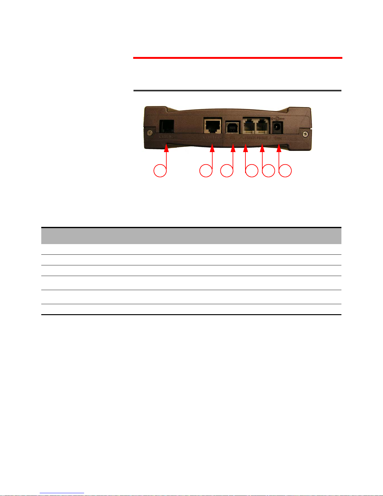
CPVA 500 CONNECTORS DESCRIPTION
Fig. 2 CPVA 500 Connectors description
1 2 3 456
Tab. 2: CPVA 500 - Connection Indication
Port
Number
Function Indication Remarks
1ADSL INADSL Uplink Port with RJ11 connector To ADSL WAN Uplink
2ETHERNETETHERNET 10/100 BaseTX with RJ45 connector Connect to user device [PC] through CAT5 cable
3USBUSB B type port - v. 1.1, 12Mbps Connect to user device [PC] through USB cable
4PHONE 1FXS with RJ11 connector
Connect to user analogue telephone through
phone cable
5PHONE 2FXS with RJ11 connector
Connect to user analogue telephone through
phone cable
612 VdcPower Supply Input Use the provided Power Supplier

Telsey telecommunications
Installation
5
MT500--SIEN12
Chapter 3
Installation
GENERAL ADVICES AND SECURITY RULES
Install the Access Gateway in a room with a temperature ranging between 5°C
and 45°C, and a relative humidity ranging from 5% to 85%. It is recommended
to avoid abrupt changes of temperature and humidity.
Leave a 10-15 cm of space around the Access Gateway in order to allow correct
aeration. Do not expose to direct sunlight. The device has to always be
connected to the electrical network. In order to avoid fire or electrical shock,
do not install it in a wet or humid environment.
Do not defuse any parts of the Access Gateway. Do not execute operations on
the internal parts for security reason. Do not insert any object into the Access
Gateway. Use only the wall adapter present in the package and the original
spare parts. The socket outlet shall be installed near the equipment and shall
be easily accessible.
Ask for experienced assistance for any type of repair.
Do not cover the Serial Number and Mac Address label. The Serial Number and
the Mac Address will be requested during any call to the Customer Service.

Telsey telecommunications
Installation
MT500--SIEN12
6
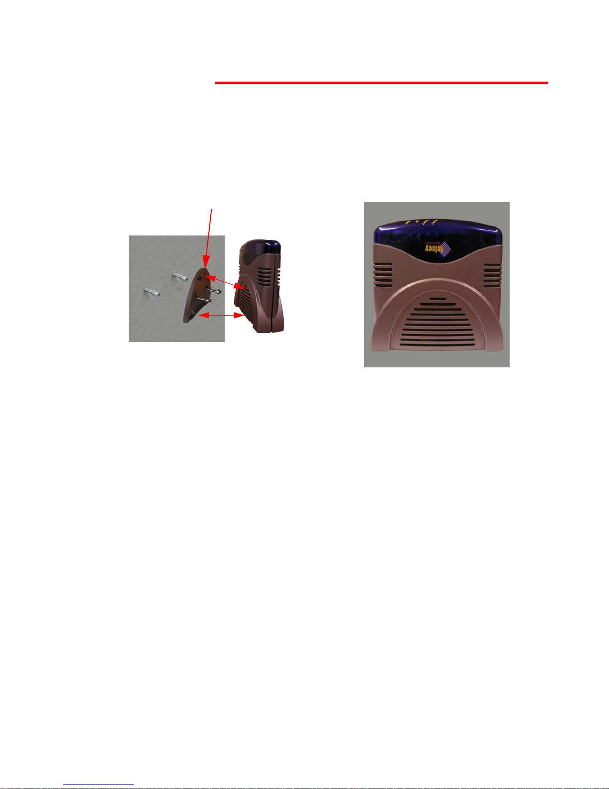
CPVA 500 PLACEMENT
CPVA500 can be positioned in a place compatibled with cable length and where
the airflow is enough to cool off the equipment.
CPVA500 can be installed either on a flat or on a vertical surface (wall
placement).
In case of table placement, use the provided vertical or horizontal support.
Horizontal Support
Fig. 3 Table Placement - Horizontal Support
Vertical Support
Fig. 4 Table Placement - Vertical Support
Telsey telecommunications
Installation
7
MT500--SIEN12
It is possible to place the Access Gateway on the wall by using the appropriate
support (provided) and screw-anchors (not provided, we suggest to use two
Fischer S4 screw anchors).
Wall Support
Fig. 5 Wall Placement: Wall Support

Telsey telecommunications
Installation
MT500--SIEN12
8

Telsey telecommunications
SIP Protocol
9
MT500--SIEN12
Chapter 4
SIP Protocol
INTRODUCTION
The Session Initiation Protocol (SIP) is a signalling protocol used for
establishing sessions in an IP network. A session could be a simple two-way
telephone call or it could be a collaborative multi-media conference session.
Since SIP is part of a IETF (Internet Engineering Task Force) specification, it
extends the open-standard spirit of the Internet to messaging, enabling remote
computers, phones, televisions and software to communicate.
Members in a session can communicate via multicast or via a mesh of unicast
relations, or via a combination of these. SIP supports session descriptions that
enable participants to agree on a set of specific media types. SIP is not tied to
any particular conference control protocol. In essence, SIP has to provide or
enable the following functions:
• Name translation and user location: ensuring that the call reaches the
called party wherever it is located. Carrying out any mapping of descriptive
information to location information. Ensuring that details of the nature of
the call are fully supported.
• Feature negotiation: this allows the group involved in a call to agree on
the features supported, recognizing that not all the parties can support the
same level of features.
• Call participant management: during a call, a participant can bring other
users onto the call or cancel connections to other users. Besides, users could
be transferred or placed on hold.
• Call features changes: a user should be able to change the call
characteristics during the course of the call. For example, a call may have
been set up as 'voice-only', but the users may need to enable a video
function.
SIP fulfils these functions and re-uses other web elements to make it flexible
and scalable.
Rather than defining a new type of addressing system, SIP addresses users by
an email-like address. Each user is identified through a hierarchical URL that is
built around elements such as a user's phone number or host name (for
example,
sip:user@telsey.com). This means that it is just as easy to
redirect someone to another phone as it is to redirect someone to a webpage.

Telsey telecommunications
SIP Protocol
MT500--SIEN12
10
In this sense, SIP borrows from the email model, using the Domain Name
System, to deliver requests to the server that can appropriately cope with
them. This also simplifies the integration of voice and email.
SIP is also transport layer indipendent. Therefore, the underlying transport
could be IP over ATM. SIP uses the User Datagram Protocol (UDP) as well as
the Transmission Control Protocol (TCP), flexibly connecting users independent
of the underlying infrastructure.
SIP provides the necessary protocol mechanisms so that end systems and
proxy servers can provide services:
• User location
• User capabilities
• User avaliability
•Call setup
• Call handling
• Call forwarding
• Callee and calling number delivery
• Personal mobility, i.e. the ability to reach a called party under a
single, location-independent address regardless the change of
terminal by the user
• Terminal type negotiation and selection
• Terminal capability negotiation
• Caller and callee authentication
• Blind and supervised call transfer
• Invitation to multicast conferences.
Protocol Components
There are four basic components within SIP:
1) SIP user agent
2) SIP network server
3) SIP Registration service
4) SIP Event and Presence server
The user agent is the end system component for the call and the SIP server is
the network device that handles the signalling associated with multiple calls.
The user agent itself has a client element, the User Agent Client (UAC) and a
server element, the User Agent Server (UAS). The client element initiates the
calls and the server element answers the calls. This allows peer-to-peer calls
to be made using a client-server protocol.
The main function of the SIP servers is to provide name resolution and user
location, since the caller is unlikely to know the IP address or host name of the
called party, and to pass on messages to other servers using next hop routing
protocols.
SIP servers can operate in three different modes:
• Stateful proxy mode

Telsey telecommunications
SIP Protocol
11
MT500--SIEN12
• Stateless proxy mode
• Re-direct server
The difference between these modes is that a server in a stateful mode
remembers the incoming requests it receives, along with the responses it sends
back and the outgoing requests it sends on.
A server in a stateless mode forgets all information once it has sent a request.
These stateless servers are likely to be the backbone of the SIP infrastructure
while stateful-mode servers are likely to be the local devices close to the user
agents, controlling domains of users.
A re-direct server receives the request, but instead of passing it onto the next
server, it sends a response to the caller party, indicating the address for the
called user. This method enables the provisioning of the address for the caller,
in order make it possible to contact the called party directly at the next server.
The SIP Registration Service provides a means for a particular device to
register to use a SIP address. As seen at the beginning of this chapter, SIP
addresses use ‘URLs’ based on the same addressing scheme used in the web
and similar in form to an email address. The SIP address provides a single
address of record for the user that delivers a one number service for all
communications applications. Users can dynamically register the devices
through which they may be contacted for all types of applications. As a result,
people will no longer have to hand out multiple contact addresses as the system
will automatically handle the distribution of all types of calls appropriately
through the proxy and redirect servers.
SIP Event and Presence Servers allow the effective sharing of information about
and between users and/or applications.
SIP Signalling
Here is reproduced a simple procedure of a call set-up:
a) The caller (User Agent Caller) sends a request with the SIP URL
of the called party.
b) If the client knows the location of the other party, is sends the
request directly to its IP address. If the location is unknown, the
client can send it to a SIP network server, which has been
locally configured.
c) The server will try to resolve the called user's location and
sends the request to them. There are many ways it can do this:
searching the DNS or accessing databases. Alternatively, the
server may be a redirect server that may return the called user
location to the calling client for it to try directly. During the
course of locating a user, one SIP network server can proxy or
redirect the call to additional servers until it arrives at one that
definitely knows the IP address where the called user can be
found.
d) Once found, the request is sent to the user. In the simplest
case, the user's telephony client receives the request, that is,
the user's phone rings. If the user takes the call, the client
responds to the invitation with the designated capabilities of

Telsey telecommunications
SIP Protocol
MT500--SIEN12
12
the client software and a connection is established. If the user
declines the call, the session can be redirected to a voice mail
server or to another user.
SIP has two additional significant features.
1) A stateful SIP server's ability to split an incoming call so that several
extensions can be rung at once. The first extension to answer takes the
call.
2) SIP's unique ability to return different media types within a single
session.
SIP Methods
The commands that SIP uses are called methods. SIP defines the following
methods:
Protocol Header Structure
The protocol is composed of:
a) A start line
b) A message header
c) An empty line
d) An optional message body.
R
EQUEST MESSAGES
The format of the Request Packet header is shown in the following figure:
SIP Method Description
INVITE Invites a user to a call
ACK Used to facilitate reliable message exchange for
INVITEs
BYE Terminates a connection between users or declines a
call
CANCEL Terminates a request, or search, for a user
OPTIONS Solicits information about a server’s capabilities
REGISTER Registers a user’s current location
INFO Used for mid-session signalling
M
ETHOD
R
EQUEST
URI SIP V
ERSION

Telsey telecommunications
SIP Protocol
13
MT500--SIEN12
Method - It is the method to be performed on the resource. All the possible
methods are listed in the previous table
Request URI - A SIP URL or a general Uniform Resource Identifier. It
represents the user or service to which this request is being addressed.
SIP Version - The SIP version being used.
R
ESPONSE MESSAGE
The format of the Response Message header is shown in the following figure:
SIP Version - The SIP version being used.
Status Code - A 3-digit integer code of the attempt to understand and satisfy
the request.
Reason Phrase - A textual description of the status code.
SIP V
ERSION
S
TATUS CODE
R
EASON PHRASE

Telsey telecommunications
SIP Protocol
MT500--SIEN12
14
Telsey telecommunications
Web Interface
15
MT500--SIEN12
Chapter 5
Web Interface
USING THE WEB-BASED USER INTERFACE
To configure the CPVA500 for the first time, the configuration PC must have a
static IP address within the 192.168.1.x subnet.
Perform the following steps to bring up the Web User Interface:
1) Connect an Ethernet cable between the CPVA500 and a PC configured to
use subnet 192.168.1.x.
2) To configure the PC to use subnet 192.168.1.x, right click on the Local
Area Connection under the Network and Dial-Up connection window
and select Properties.
3) Select Internet Protocol (TCP/IP) and then click on the Properties
button.
4) Select the Use the following IP address option and then enter the IP
address as 192.168.1.x
1
, where x is some number between 2 and 254.
Click the tab button to select the subnet mask as 255.255.255.0.
5) If the CPVA500 has not been turned on, turn on the power. Wait about
one minute.
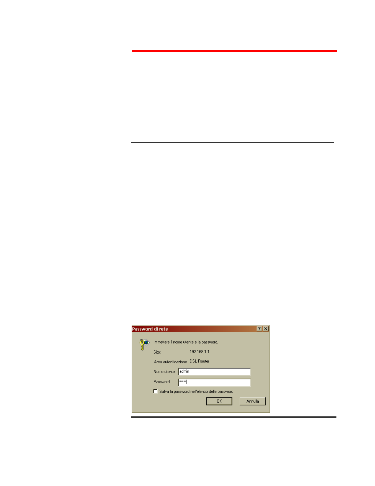
6) In a Web browser on the PC, connect to http://192.168.1.1/ to enter
the router's configuration program. The browser should connect and you
should see the Enter Network Password screen shown in the following
figure. If the browser does not connect, the router may not have an
image. In this case, follow the instructions on page 69 to update the
CPVA500 image.
7) Type admin in the User Name and Password fields, and click OK. These
values can be changed later in the Web User Interface.
1. Note that Ethernet and USB interface share the same subnet, since they are bridged within
the router.

Telsey telecommunications
Web Interface
MT500--SIEN12
16
USB Drivers Installation
In order to use USB port, it is necessary to install Microsoft Windows Remote
NDIS USB drivers.
Follow these steps to complete the installation:
1) On Windows 98, Windows Me, Windows 2000 or Windows XP PC, enter
"
mkdir \temp\usb" to create a temporary directory.
2) Enter "cd \temp\usb" to change to the temporary directory.
3) Copy the tlsID_cpva500_winusbrndis.zip file to the Windows PC.
4) Unzip tlsID_cpva500_winusbrndis.zip into the temporary directory.
5) Connect a USB cable between the PC and the CPVA500.
6) The first time that this is done, the Windows PC displays the "New
Hardware Found" dialog. When prompted for the location of the driver,
specify the temporary directory, \temp\usb.
7) On Windows 98 and Windows Me, you will need to reboot the Windows
PC.
8) The CPVA500 Windows USB driver looks like a network adapter card to
Windows. It is bound to TCP/IP. Configure TCP/IP appropriately for your
environment.
The driver is now operational.

Telsey telecommunications
Web Interface
17
MT500--SIEN12
Factory Default Configuration
During Power on initialization, the CPVA500 initializes all configuration
attributes to default values. It will read in the configuration profile from the
permanent storage section on the flash memory. The default values are
overridden when identical attributes with different values are configured.
The configuration profile in the permanent storage can be created via Web User
Interface or Telnet User Interface, or the other management protocols.
The factory default configuration can be restored in the following method:
•Via Web page, by clicking the Restore Default Settings option in
the Restore Default screen;
•Via Telnet with
restoredefault command.
•Via Phone, when the unit becomes unreachable. Refer to page 71
for futher information.
The default parameters of the device are the following:
• LAN port IP address: 192.168.1.1
•LAN port Netmask: 255.255.255.0
•Local Administrator
1
account name: admin
• Local Administrator account password: admin
• Local Non-Administrator
2
account name: user
• Local Non-Administrator account password: user
• Remote WAN access
3
: enabled all service
• Remote WAN access account name: support
• Remote WAN access account password: support
• DHCP server on LAN interface: disabled
Note
The parameters not included in the previous list are not set.
1. The Local Access screen allows you to set and confirm “admin” unrestricted access to change
the configuration of the router, but cannot obtain access from WAN. Both username and
password have a maximum length of 15 characters.
2. The User Access screen allows you to set and confirm “user” access to view the configuration, statistics, and to update the router software via LAN, but not via WAN. Both username
and password have a maximum length of 15 characters.
3. The Remote technical support account allows the local administrative user to explicitly enable a remote technician to access Telsey Router user interface and allows it to send ping
response packet. This account allows you to set and confirm “support” access for router
maintenance and diagnostics. The remote support access will not work in bridge mode since
there is no public IP address assigned to the router. Both username and password have a
maximum length of 15 characters.
Telsey telecommunications
Web Interface
MT500--SIEN12
18
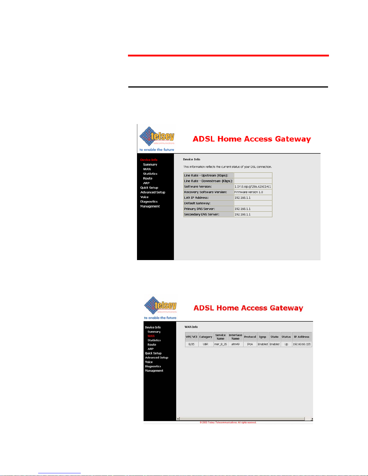
DEVICE INFO
Summary
After login, the Device Info screen appears as shown in the following figure.
WAN
The following page shows the settings currently configured in the WAN setup
(Advanced Setup section).
Telsey telecommunications
Web Interface
19
MT500--SIEN12
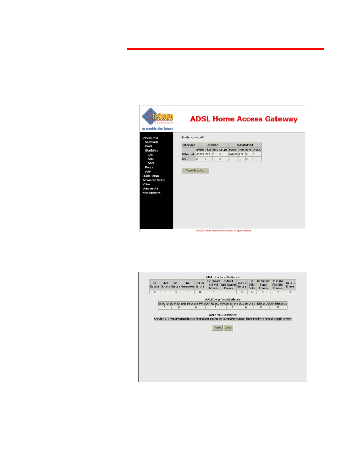
Statistics LAN
The LAN Statistics screen shows interface statistics for Ethernet and USB
interfaces.
ATM Statistics
The following figure shows the ATM statistics screen.

Telsey telecommunications
Web Interface
MT500--SIEN12
20
Tab. 3: ATM Layer Statistics over ADSL interface
Field Description
InOctets Number of received octets over the interface
OutOctects Number of transmitted octets over the interface
InErrors Number of cells dropped due to uncorrectable HEC
errors
InUnknown Number of received cells discarded during cell header
validation, including cells with unrecognized VPI/VCI
values, and cells with invalid cell header patterns. If
cells with undefined PTI values are discarded, they are
also counted here.
InHecErrors Number of cells received with an ATM Cell header HEC
error.
InInvalidVpiVciErrors Number of cells received with an unregistered VCC
address.
InPortNotEnabledErrors Number of cells received on a port that has not been
enabled.
InPtiErrors Number of cells received with an ATM header Payload
Type Indicator (PTI) error.
InIdleCells Number of idle cells received.
InCircuitTypeErrors Number of cells received with an illegal circuit type.
InOamRmCrcErrors Number of OAM and RM cells received with CRC errors.
InGfcErrors Number of cells received with a non-zero GFC.
Tab. 4: ATM AAL5 Layer Statistics over ADSL interface
Field Description
InOctets Number of received AAL5/AAL0 CPCS PDU octets.
OutOctets Number of AAL5/AAL0 CPCS PDU octets transmitted.
InUcastPkts Number of received AAL5/AAL0 CPCS PDUs passed to
a higher-layer.
OutUcastPkts Number of AAL5/AAL0 CPCS PDUs received from a
higher-layer for transmission.
InErrors Number of AAL5/AAL0 CPCS PDUs received that
contain an error. The types of errors counted include
CRC-32 errors, SAR timeout errors and oversized SDU
errors.
OutErrors Number of AAL5/AAL0 CPCS PDUs that could not be
transmitted due to errors.
InDiscards Number of AAL5/AAL0 CPCS PDUs discarded due to an
input buffer overflow condition.
OutDiscards This field is not currently used.
Telsey telecommunications
Web Interface
21
MT500--SIEN12
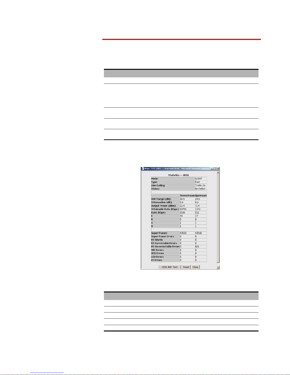
ADSL Statistics
The following figure shows the ADSL statistics screen.
Tab. 5: ATM AAL5 Layer Statistics for each VCC over ADSL interface
Field Description
CrcErrors Number of PDUs received with CRC-32 errors.
SarTimeOut Number of partially re-assembled PDUs which were
discarded because they were not fully re-assembled
within the required time period. If the re-assembly
timer is not supported, then this object contains a zero
value.
OverSizedSDUs Number of PDUs discarded because the corresponding
SDU was too large.
ShortPacketError Number of PDUs discarded because the PDU length
was less than the size of the AAL5 trailer.
LengthErrors Number of PDUs discarded because the PDU length did
not match the length in the AAL5 trailer.
Tab. 6: ADSL Statistics field
Field Description
Mode Modulation protocol G.DMT or T1.413
Type Channel type, Interleave or Fast
Line Coding Trellis coding on/off
Status Link Status
SNR Margin (dB) Signal to Noise Ratio (SNR) margin

Telsey telecommunications
Web Interface
MT500--SIEN12
22
With the ADSL Statistics
window, a Bit Error Rate
Test can be started using
the ADSL BER Test
button. The windows
associated with this test
include a start/
configuration window,
and in-process window
and a results window.
Select the Tested Time
(in seconds) and press
Start.
Attenuation (dB) estimate of average loop attenuation in the
downstream direction
Output Power (dBm) total upstream output power
Attainable rate (Kbps) maximum achievable downstream rate
K number of data bytes in ADSL data frame (DMT
symbol)
S length of Reed-Solomon code word in data frames
R number of redundant check bytes per Reed-Solomon
code word
D interleaver depth
Super Frames total number of super frames
Super Frames Errors number of super frames received with errors
RS Words total number of Reed-Solomon code words
RS Correctable Errors number of RS words with correctable errors
RS uncorrectable Errors number of RS words with uncorrectable errors
HEC Errors total number of Header Error Checksum errors
LCD Errors total number of Loss of Cell Delineation
Tab. 6: ADSL Statistics field
Field Description

Telsey telecommunications
Web Interface
23
MT500--SIEN12
Route
The following page shows the routing information.
ARP
The following page shows the ARP configuration.

Telsey telecommunications
Web Interface
MT500--SIEN12
24
QUICK SETUP
Quick Setup enables a user-friendly interface to configure CPVA500.
DSL Auto-connect is a feature that automatically scans PVC and tries to
estabilish an ADSL connection. This feature, though, takes a long time,
especially for the VPI/VCI scanning. We suggest to obtain the correct network
settings from the ISP and then manually configure the CPVA500, by deselecting
“DSL Auto-Connect” check box.
An example of DSL Auto-Connect configuration page is shown in the following
figure:

Telsey telecommunications
Web Interface
25
MT500--SIEN12
If DSL Auto-Connect is not selected, then it is possible to manually configure
VPI/VCI, Connection Type, WAN IP Settings. For all the information regarding
these settings, please refer to the Advanced Setup section starting from
page 28.

Telsey telecommunications
Web Interface
MT500--SIEN12
26
Quick setup navigation menu can be represented in the following diagram.
* In case of configuration via “Quick Setup”, Device Setup for LAN interface
can be configured by setting the following page (for PPPoA, PPPoE, MER, IPoA):
VPI/VCI
Connection Type
PPPoA PPPoE MER IPoA Bridging
PPP Username
Password
WAN IP
Settings
NAT, QoS
Bridge IP
Settings
LAN Device Setup*
Summary
WAN, QoS

Telsey telecommunications
Web Interface
27
MT500--SIEN12
LAN Device Setup for Bridging mode is represented in the following page.

Telsey telecommunications
Web Interface
MT500--SIEN12
28
ADVANCED SETUP
WAN
WAN Setup
By clicking on WAN in the Advanced Setup menu it is possible to begin the
configuration of WAN interfaces. The following screen shows the inital situation,
when no WAN interface is present.
By clicking on Add button, it is possible to begin the setup.
ATM PVC Configuration
The first page to configure is ATM PVC Configration. These settings are
usually given by Internet Service Providers.
In this page it is possible to set VPI, VCI and Service Category.
Avaliable Service Categories are:
• UBR (Unspecified Bit Rate) without PCR (Peak Cell Rate)
•UBR with PCR
• CBR (Constant Bit Rate)
• Non Realtime VBR (Variable Bit Rate)
• Realtime VBR
The following figure shows the ATM PVC Configuration Page

Telsey telecommunications
Web Interface
29
MT500--SIEN12
In case of UBR with PCR and CBR, it is possible to set Peak Cell Rate [cells/s]
value.
In case of Non Realtime VBR, it is possible to set values for:
• Peak Cell Rate [cells/s]
• Sustainable Cell Rate [cells/s]
• Maximum Burst Size [cells]
Click on Next to set Connection Type.
Connection Type
The Connection Type page allows to select the type of encapsulation protocol
and encapsulation mode over the ATM PVC that has been selected in the
previous page.
Avaliable connection types are:
• PPP over ATM (PPPoA)
• PPP over Ethernet (PPPoE)
• MAC Encapsulation Routing (MER)
• IP over ATM (IPoA)
• Bridging
Depending on the selected network protocol, it is then possible to choose an
appropriate encapsulation mode (VC/MUX, LLC/ENCAPSULATION, LLC/SNAP
BRIDGING, VC/MUX, LLC/SNAP ROUTING).

Telsey telecommunications
Web Interface
MT500--SIEN12
30
The following figure shows the Connection Type page.
The following table shows all the encapsulation modes avaliable for each
network protocol.
Each Network Protocol needs further configurations, which can be set by
clicking on Next.
PPPoA
If PPP over ATM is chosen, regardless of the selected encapsulation mode, the
following screen requires to set PPP Username and Password. The Password
requirement is dependent on the particular requirements of the ISP or ADSL
Service Provider.
PPP Username max. length is 256 characters, PPP Password max. length is 32
characters.
Tab. 7: Network Protocol and Encapsulation Mode
Protocol Encapsulation Mode
PPP over ATM VC/MUX, LLC/ENCAPSULATION
PPP over Ethernet LLC/SNAP BRIDGING, VC/MUX
MAC Encapsulation Routing LLC/SNAP BRIDGING, VC/MUX
IP over ATM LLC/SNAP ROUTING, VC/MUX
Bridging LLC/SNAP BRIDGING, VC/MUX

Telsey telecommunications
Web Interface
31
MT500--SIEN12
The following figure shows PPP Username and Password page.
CPVA500 can be configured to disconnect if there is no activity for a period of
time by selecting the Disconnect if no activity box. Default time is 30
minutes.
As Authentication Method, either “PAP”, or “CHAP” can be used. If “AUTO”
is selected, then the authentication protocol is automatically selected.
PPP IP extension is a special feature deployed by some service providers.
Unless your service provider specifically requires this setup, do not select it.
The PPP IP Extension supports the following conditions:
• Allows only one PC on the LAN
• The public IP address assigned by the remote using the PPP/IPCP protocol
is actually not used on the WAN PPP interface. Instead, it is forwarded to the
PC's LAN interface through DHCP. Only one PC on the LAN can be connected
to the remote since the DHCP server within the ADSL router has only a
single IP address to assign to a LAN device.
• NAPT and firewall are disabled when this option is selected.
• The ADSL router becomes the default gateway and DNS server to the PC
through DHCP using the LAN interface IP address.
• The ADSL router extends the IP subnet at the remote service provider to the
LAN PC. That is, the PC becomes a host belonging to the same IP subnet.
• The ADSL router bridges the IP packets between WAN and LAN ports, unless
the packet is addressed to the router's LAN IP address.
By clicking on Next, it is then possible to enable or disable WAN service (and
assign a service name), IGMP multicast (not supported yet) and Quality of
Service. QoS can be activated and then controlled by means of the relative
menu (Advanced Setup --> Quality of Service). Note that enabling QoS for a

Telsey telecommunications
Web Interface
MT500--SIEN12
32
selected PVC improves performance for selected classes of applications, but
also reduces the number of available PVC’s.
The following figure shows the relative page.
By clicking on Next, the WAN Setup Summary shows up.

Telsey telecommunications
Web Interface
33
MT500--SIEN12
PPPoE
If PPP over Ethernet is chosen, regardless of the selected encapsulation
mode, the configuration pages are identical to PPP over ATM. All the
considerations explained in the PPPoA section remain valid.
MER
If MAC Encapsulated Routing is chosen, it is then necessary to configure
WAN IP Settings.
The following figure shows WAN IP Settings page for MER protocol.
The IP Address, Default Gateway and DSN Server can be obtained
automatically through the DHCP client in the CPVA500.
Otherwise, the user must enter static values in the appropriate fields.
After that, by clicking on Next, it is possible to enable Network Address
Translation (NAT). If the LAN is configured with a private IP address, the user
should select this checkbox. The NAT submenu on the left side main panel will
be displayed after reboot. The user can then configure NAT-related features
after the system comes up. If a private IP address is not used on the LAN side,
this checkbox should be deselected to free up system resources for better
performance. When the system comes back after reboot, the NAT submenu will
not be displayed on the left main panel.
Refer to page 37 in order to configure NAT features.
Besides NAT, from this page it is possible to enable WAN service (and assign a
service name), IGMP multicast (not supported yet) and Quality of Service. QoS
can be activated and then controlled by means of the relative menu (Advanced
Setup --> Quality of Service). Note that enabling QoS for a selected PVC
improves performance for selected classes of applications, but also reduces the
number of available PVC’s.
The following figure shows NAT, WAN Service, IGMP and QoS page.

Telsey telecommunications
Web Interface
MT500--SIEN12
34
By clicking on next, the setup summary will be displayed. Click on Save to apply
the settings.

Telsey telecommunications
Web Interface
35
MT500--SIEN12
IPoA
If IP over ATM is chosen, it is then necessary to configure WAN IP Settings.
Enter WAN IP Address, Subnet Mask, Default Gateway and DNS Servers. Note
that DHCP is not supported, meaning that automatic provisioning is not
available when using IPoA.
After that, by clicking on Next, it is possible to enable Network Address
Translation (NAT). If the LAN is configured with a private IP address, the user
should select this checkbox. The NAT submenu on the left side main panel will
be displayed after reboot. The user can then configure NAT-related features
after the system comes up. If a private IP address is not used on the LAN side,
this checkbox should be deselected to free up system resources for better
performance. When the system comes back after reboot, the NAT submenu will
not be displayed on the left main panel.
Refer to page 37 in order to configure NAT features.
Besides NAT, from this page it is possible to enable WAN service (and assign a
service name), IGMP multicast (not supported yet) and Quality of Service. QoS
can be activated and then controlled by means of the relative menu (Advanced
Setup --> Quality of Service). Note that enabling QoS for a selected PVC
improves performance for selected classes of applications, but also reduces the
number of available PVC’s.
The following figure shows NAT, WAN Service, IGMP and QoS page.

Telsey telecommunications
Web Interface
MT500--SIEN12
36
The following figure shows Network Address Traslation Settings page.
By clicking on next, the setup summary will be displayed. Click on Save to apply
the settings.

Telsey telecommunications
Web Interface
37
MT500--SIEN12
NAT Configuration
After enabling NAT (for MER, IPoA, PPPoA, PPPoE) and rebooting, on the left
side menu a new NAT submenu comes up. Network Address Translation (NAPT)
allows a single device, such as a router, to act as an agent between the Internet
(or "public network") and a local (or "private") network. This means that only
a single, unique IP address is required to represent an entire group of
computers.
Implementing dynamic NAPT automatically creates a firewall between your
internal network and outside networks, or between your internal network and
the Internet. NAPT only allows connections that originate inside the sub
domain. Essentially, this means that a computer on an external network cannot
connect to your computer unless your computer has initiated the contact. You
can browse the Internet and connect to a site, and even download a file; but
somebody else cannot latch onto your IP address and use it to connect to a port
on your computer. Under the NAPT environment, all computers behind the
NAPT are not accessible from outside (i.e., the WAN). However, if public
services, such as web servers, ftp servers or email servers, are needed from
your private network, a virtual server can be configured to set up permit
secured access. A virtual server setup enables a connection from outside to be
redirected to a host running the services on the private subnet. This host
running the services is called a virtual server (a virtual server is synonymous
with IP forwarding).
The NAT dialog box allows you to configure Virtual Servers and DMZ Host
settings by adding, removing and saving.
The following figures show the NAT configuration pages.
The first page is NAT Virtual Servers. Virtual server allows you to direct
incoming traffic from WAN side (identified by Protocol and External Port) to the
Internal server with private IP address on the LAN side. The internal port is

Telsey telecommunications
Web Interface
MT500--SIEN12
38
required only if the external port needs to be converted to a different port
number used by the server on the LAN side.
Click on Add to add a Virtual server and display the following page.
Click on Remove, after selecting the Virtual Server, to delete the Virtual Server.
After clicking on Add, it is possible to select the service name and IP address in
order to forward IP packets for this service to the specified server.
Tab. 8: NAT Virtual Servers main page
Option Description
Server Name The service the virtual server will provide (web, ftp,
email).
Protocol The protocol (UDP,TCP or both) used by the service.
External Port The port or port range that an outside connection will
use.
Internal Port The port or port range that the virtual server will use
to listen to the connection from outside.
Server IP Address The internal (private) IP address of the virtual server.

Telsey telecommunications
Web Interface
39
MT500--SIEN12
By clicking on Port Triggering in the NAT menu, you will enter NAT Port
Triggering configuration page.
Some applications require that specific ports in the Router’s firewall be opened
for access by the remote parties. Port Triggering dynamically opens up the
“Open Ports” in the firewall when an application on the LAN initiates a TCP/UDP
connection to a remote party using the “Triggering Ports”. The Router allows
the remote parties from the WAN side to estabilish new connections back to the
application on the LAN side using the “Open Ports”.
The following figure shows NAT Port Triggering main page.
Tab. 9: NAT Virtual Server fields
Option Description
Service Name Allows the selection of an existing service from a drop-
down-menu, or an entry of a custom service entry is
the name is known, but not listed in the existing list.
Protocol Allows the selection of a transport protocol (UDP,TCP
or both).
External Port (Start/End) Allows the entry of an individual external port, or
range of ports.
Internal Port (Start/End) Allows the entry of an individual internal port, or range
of ports.
Server IP address Allows the entry of an internal server IP address.

Telsey telecommunications
Web Interface
MT500--SIEN12
40
By clicking on Add, the following page shows up.
Select an application from the drop down menu, or type in a custom application
name.
Enter the trigger port range (Trigger Port Start --> Trigger Port End) and the
Trigger Protocol (TCP, UDP, TCP/UDP). Then, enter the open port range (Open
Port Start --> Open Port End) and the Open Protocol (TCP, UDP, TCP/UDP).
By clicking on DMZ Host, you will enter the DeMilitarized Zone Host options
page.
The DeMilitarized Zone Host option is used to forward IP packets from the WAN
that do not belong to any of the applications configured in the virtual servers
table, to the DMZ host computer. While virtual server can only forward
(redirect) a limited number of services (ports), DMZ hosting allows all the
services (ports) running on the DMZ host, to be accessible externally.
The following figure shows the DMZ Host page.

Telsey telecommunications
Web Interface
41
MT500--SIEN12
To configure the DMZ, type in the computer’s IP address in the DMZ Host IP
Address field and click on Save/Apply. Clear the IP address field and click on
Save/Apply to deactivate the DMZ host.
Bridging
If Bridging is chosen, by clicking on Next, it is then possible to set the following
page (BRIDGE IP Settings).

Telsey telecommunications
Web Interface
MT500--SIEN12
42
Enter information provided by the ISP to configure the WAN IP Settings. Note
that DHCP can be enabled for PVC in Bridge mode if “Obtain an IP address
automatically” is chosen. The system will start without IP address and the
obtained IP address will be assigned to the bridge. Changing the DNS effects in
the whole system. Configuring them with static values will disable the
automatic assignment from DHCP or other WAN connection.
The next page allows to disable a WAN service indicated in the “Service Name”
field.

Telsey telecommunications
Web Interface
43
MT500--SIEN12
After that, by clicking on Next the setup summary will be displayed. Click on
Save to apply the settings.
LAN
By clicking on LAN in the Advanced Setup menu, the following page will show
up.

Telsey telecommunications
Web Interface
MT500--SIEN12
44
Configure the DSL Router IP address and Subnet Mask for LAN interface. It is
also possible to enable DHCP server on the LAN, by defining the IP address
range and leased time. A second IP address and Subnet Mask for LAN interface
can be enabled by selecting the last checkbox.
Save button only saves the LAN configuration data. Save/Reboot button saves
the LAN configuration data and reboots the router to make the new
configuration effective.
Quality of Service
1
By clicking on Quality of Service in the Advanced Setup menu, it is possible
to configure network traffic classes.QoS button will only be displayed to a
qualified PVC when all of the following conditions are met:
• PVC is not in bridge mode (i.e. the WAN protocol can be PPPoA,
PPPoE, IPoA, MER);
• PVC is in set to one of the following ATM service category: UBR
with PCR, UBR without PCR, non realtime VBR;
• There are enough ATM TX queues left in the System.
If no traffic class is set, then it is possible to configure QoS by clicking on Add.
If a class has already been set, then it is possible to remove it by selecting
“remove” checkbox and clicking on Remove.
Each QoS-enabled PVC will consume 3 ATM TX queues. QoS consumes 1 TX
queue for transmitting OAM F5 cells for all PVC’s
2
. The overall number of ATM
TX queues for the whole system is 8. Setting up the first PVC with QoS enabled
1. Quality of Service is currently not supported in ADSL AnnexB software release.
2. This restriction is temporary and will be removed in the future.

Telsey telecommunications
Web Interface
45
MT500--SIEN12
requires 4 TX queues. Setting up the second PVC with QoS enabled needs 3 TX
queues.
The following table shows the system capacity for maximum number of PVC’s,
with or without QoS enabled:
By clicking on Add, then the following page shows up.
IP QoS is executed in the IP layer. It will classify traffic according to the
classification rule. Each rule may contain a combination of the following
conditions: protocol (TCP, UDP, ICMP), source IP address/subnet mask,
destination IP address/subnet mask, source port (one or range), destination
port (one or range). The result of matching a classification rule will produce a
priority (high, medium, low) and a Type of Service (don’t care, Normal Service,
Minimum Cost, Maximum Reliability, Maximum Throughput, Minimum Delay).
Note that the original IP header TOS and PRECEDENCE values are not used in
the classification.
Tab. 10: System capacity - PVC/QoS
Maximum
Configurations
Number of PVC’s with
QoS enabled
Number of PVC’s with
QoS Disabled
Configuration #1 21
Configuration #2 14
Configuration #3 08

Telsey telecommunications
Web Interface
MT500--SIEN12
46
The Type of Service (TOS) of the matching rule will overwrite the original IP
header TOS field if “don’t care” is not selected.
The priority of the matching rule determines which ATM TX queue to send over
this PVC if the packet is routed to this PVC. The ATM SAR scheduler transmits
the packet according to the following order:
1) ATM service category from the highest to the lowest order: CBR, rt-VBR,
nrt-VBR, UBR
2) For the same service category: Proirity level from high to medium to low
3) For the same priority level: round robin.
IP QoS will only take effect if the packet is routed to a QoS-enabled PVC. If it
is routed to a regular QoS-disabled PVC, it will be transmitted at the same
priority level as the low priority of a QoS-enabled PVC of the same ATM service
category.
Click on Save/Apply to store the QoS setting.
Routing
By clicking on Routing in the Advanced Setup menu, it is possible to configure:
•Default Gateway
• Static Route
•RIP
Default Gateway
The following figure shows Default Gateway page, accessed by clicking on
Default Gateway on the Advanced Setup --> Routing menu.

Telsey telecommunications
Web Interface
47
MT500--SIEN12
If Enable Automatic Assigned Default Gateway checkbox is selected, this router
will accept the first received default gateway assignment from one of the
PPPoA, PPPoE or MER/DHCP enabled PVC(s). If the checkbox is not selected,
enter the static default gateway IP address and/or a WAN interface. Click
'Save/Apply' button to save it.
NOTE: If changing the Automatic Assigned Default Gateway from unselected
to selected, You must reboot the router to get the automatic assigned default
gateway.
Static Route
Click on Add in the following page to configure static route entry.
In case a static route entry is already present, then select it and click on
Remove to delete it.
The following figure shows the Static Route Add page.

Telsey telecommunications
Web Interface
MT500--SIEN12
48
Enter the destination network address, subnet mask, gateway address and/or
avaliable WAN interface. By clicking on Save/Apply, the entry is included in the
routing table.
RIP
By clicking on RIP, the following page will show up.

Telsey telecommunications
Web Interface
49
MT500--SIEN12
To activate RIP for the device, select “Enabled” radio button for global RIP
mode. To configure an individual interface, select the desired RIP version (1, 2
or both) and operation (Active, Passive), followed by placing a check in the
“Enabled” checkbox for the interface. Click the “Save/Apply” button to save the
configuration, and to start or stop RIP based on the global RIP mode selected.
DSL
The DSL Settings dialog box allows you to select an appropriate modulation
mode.
By clicking on DSL in the Advanced Setup menu, the following page will show
up.
Tab. 11: DSL modulation settings
Option Description
Auto Mode (G.Dmt, G.lite or
T1.413)
Sets the system auto-sense between G.Dmt, G.lite, or
T1.413.
G.Dmt/G.lite Sets G.Dmt/G.lite if you want the system to use either
G.Dmt or G.lite mode.
T1.413 Sets the T1.413 if you want the system to use only
T1.413 mode.
G.Dmt Sets the system to use only G.Dmt mode.
G.lite Sets the system to use only G.lite mode.

Telsey telecommunications
Web Interface
MT500--SIEN12
50
By clicking on Advanced Settings, it is possible to select an appropriate test
mode.
The following page shows the DSL Advanced Settings page.
All three of these modes enable PSD measurements for each phase of training
and showtime.
Tab. 12: DSL Advanced Settings - Test mode choice
Option Description
Normal Normal mode of operation.
Reverb Send Reverb signal only.
Medley Send Medley signal only.
No retrain Stay in showtime even after the modem is
disconnected.

Telsey telecommunications
Web Interface
51
MT500--SIEN12
The Tone Selection button prompts the ADSL Tone Settings dialog box. This
allows you to select an appropriate number of upstream and downstream
tones.
Click Apply after you have made your selections.

Telsey telecommunications
Web Interface
MT500--SIEN12
52
VOICE
The Voice menu enables VoIP SIP settings.
SIP
By clicking on SIP (Voice sub-menu), the following configuration page shows
up.

Telsey telecommunications
Web Interface
53
MT500--SIEN12
• Select a WAN interface from the drop-down menu (Interface name).
• SIP Proxy Server’s IP Address and port can be typed in after selecting Use
SIP Proxy checkbox. It is also possible to use an alternate SIP Proxy Server
is case the main one is down or unreachable.
• If a SIP Registrar is required in the network, then it is possible to set its IP
Address, port and SIP Time to Live after selecting Use SIP Registrar
checkbox. It is also possible to use an alternate SIP Registrar in case the
first one is down or unreachable. TimeOut parameter determines when the
CPE sends the request to Alternative Proxy. When the TimeOut is expired
the CPE will try to go back to Proxy (Registrar).
Note: The number of requests (Retries) to send to Proxy (or Registrar), before
the CPE switches to Alternative Proxy (Alternative Registrar) MUST be specified
(1 request by default).
• If a SIP log messages server is required in the network, then it is possible
to set its IP address and port, after selecting Remote Server for SIP log
messages checkbox.
• The SIP protocol can be configured to use the UDP/TCP or BOTH protocol as
Transport protocol type.
• SDP Export Type. When the application is initiating a session, it can choose
to be the offerer or the answered. If it acts as the offerer, the application
must include an SDP packet in the INVITE. The remote UA must then
include the answer SDP packet into its 200 OK response. If the application
wants to act as the answerer, then it must not include any SDP packet into
the INVITE: it will be up to the remote UA the inclusion of an offer in its 200
OK response. After receiving an offer into a 200 OK response, the
application must include its answer into the following ACK request.
• It is possible to enable OutOfBand DTMF and assign a suitable payload of
the RTP packets, according to RFC2833. Valid payload range is from 96 to
127.
• Supplementary Services
CLIR:
• To set the caller ID restriction, dial *31# (default) then the
number.
• CLIR permanent: enable *32# (default).
• CLIR permanent: disable #32# (default).
Call Hold:
• To put a call on hold, press flash than hang up (optional).
• To return to the original call, press flash or pick up the phone.
• The phone will issue a short ring burst every 20 seconds or so
while on-hook to remind you that a call is on hold.
Call transfer:
• To transfer a call, press flash then dial the new number.
• To transfer immediately, hang up (blind transfer)
• To transfer with consultation, wait for the party to answer, consult,
and then hang up.

Telsey telecommunications
Web Interface
MT500--SIEN12
54
• To abort the transfer (if the third party does not answer), press
flash to return to the original call.
Conference calling:
• To turn a two-party call into a three-party conference call, press
flash and dial the third party.
• To place the old (current) call on hold and take the new call press
flash+2 (R2).
• To switch between the old and the new call press flash+2 (R2).
• To connect to both the old and the new call press flash+3 (R3).
Starts a 3-party conference call.
• To return in the state before the conference, press flash+2 (R2).
• To drop yourself out of the conference, hang up. The call will be
transferred (so that the other two parties remain connected to
each other).
Note: In conference mode, the conference initiator performs the audio
bridge/mixing function. There are only 2 voice streams established.
Call Waiting:
• If call waiting is enabled on a line, you will hear the call waiting
tone during a call.
• To press flash+2 to answer the second call. The first call is
automatically placed on hold.
• To switch between calls, press flash+2 (R2).
• To connect both the old and the new call flash+3 (R3). Starts a 3party conference call.
• To reject the new call without answering it, press flash+0 (R0).
• To release the old call and take the new call, press flash+1 (R1).
• To enable the call waiting feature, dial *43# (default).
• To disable the call waiting feature, dial #43# (default).
• Call forward feature settings (Busy or All) takes priority over the
call waiting feature.
• Call waiting feature is ignored on new incoming calls if there is
already a call on hold or in conference.
Call forward:
• To set the call forward on no answer, dial *61* (default), then the
number and the termination character "#". Incoming calls will be
forward if unanswered for 18 seconds (default).
• To set the call forward if busy, dial *67* (default), then the
number and the termination character "#". Incoming calls will be
immediately forwarded if the phone id off-hook.
• To set the call forward unconditional, dial *21* (default), then the
number and the termination character "#".
• To disable all the forward, dial #21# (default).
Call return:

Telsey telecommunications
Web Interface
55
MT500--SIEN12
• To place a call to the last know incoming caller (unanswered or
not), dial *69# (default).
Redial:
• To redial the last outgoing number, dial *68# (default).
SS Configuration
Use the CLI (command
suppServs) or Web page to set the special codes.
See the following table for code configuration:
The suppServer command string has the following structure:
CodeCommand, CodeCommand
Example
WO*43#,WF#43#,FU*21*
Enable Call Waiting --> *43#
Disable Call Waiting --> #43#
Enable Call Forwarding Unconditional --> *21*
SS Enable/Disable services
Use the CLI or Web page to enable or disable the service. The following table
provide information on the services and call features parameters. The services
parameter is in bitmap format. The default is 0xffff.
Tab. 13: Supplementary services codes
Supplementary service Code
Call Waiting ON WO
Call Waiting OFF WF
Call forwarding
Unconditional (All)
FU
Call forwarding if Busy FB
Call forwarding on No
answer
FA
Call forwarding OFF FF
Call Return CR
Call Redial CD
CLIR for call RT
CLIR permanent ON RO
CLIR permanent OFF RF
Tab. 14: SS bitmap codes
Bit Mask Explanation
Bit 0 0x1 Call Waiting
Bit 1 0x2 Call Forwarding
Bit 2 0x4 Call Transfer

Telsey telecommunications
Web Interface
MT500--SIEN12
56
• It is possible to set a Digest Authentication, by choosing an username and
password for each telephone line, if the SIP Registrar supports this feature.
• Type the phone numbers for Line 1 and Line 2 and select an appropriate Dial
Plan (see Appendix A for more details).
Click on Change SIP Parameters and reboot to apply new settings.
By clicking on Common (Voice sub-menu), the following page shows up.
For each available Codec (G711µ-law, G711A-law, G729), it is possible to
choose:
• Packetization time
• Echo Canceller
• Silence Suppression
• Codec Priority order: select the preferred order for the available codecs.
Bit 3 0x8 Call Hold
Bit 4 0x10 3-Way Conference
Bit 5 0x20 Call Return
Bit 6 0x40 Call Redial
Bit 7 0x80 CLIR
Tab. 14: SS bitmap codes
Bit Mask Explanation

Telsey telecommunications
Web Interface
57
MT500--SIEN12
• Country tone (North America, Italy, UK, France, Sweden, Netherlands,
Belgium and Germany)
1
• Caller ID Signal Type (FSK, DTMF)
• It is possible to activate Squelch for InBand DTMF.
• Fax passthrough codec: select the preferred codec among G711A-law,
G711µ-law. Echo canceller will be disabled when fax/modem tone has been
detected.
• HookFlash interval: type the time range, in milliseconds, for the HookFlash.
Click on Change Common parameters to apply the new settings.
1. See Appendix A for more specifications regarding Country tones.

Telsey telecommunications
Web Interface
MT500--SIEN12
58
DIAGNOSTICS
The Diagnostics menu provides feedback on the connection status of the
CPVA500 and the ADSL link. A description of each test can be obtained by
clicking on the help button associated with the test.
Without an active ADSL connection, many of the tests will not be activated, and
when the current network operating mode is in bridge, the default gateway and
DNS server tests will not be activated.
There are two buttons at the bottom of the screen:
• Rerun Diagnostic Tests
• Rerun Diagnostic Tests With OAM F4
When either of the Rerun Diagnostic Tests buttons are pressed, all the
diagnostic tests are repeated. Normally, if one or more tests return a failure
status, the user should rerun all the tests again to more thoroughly diagnose
the problems encountered.
When Rerun Diagnostic Tests With OAM F4 is pressed, ATM OAM F4 loopback
cells are also transmitted, in addition to OAM F5 cells. It is possible that the
ATM OAM F4 loopback or segment tests may not be supported by the ATM
devices in the DSL service provider's network. For this reason, the OAM F4 test
is separated from the general diagnostics tests. When an OAM F4 failure is
encountered, the output screen will appear as an F4 Fail.

Telsey telecommunications
Web Interface
59
MT500--SIEN12
The following figure shows an example of diagnostics page, when the PVC is
configured in MER mode.
The following table provides a brief description of each diagnostics test.
Tab. 15: Diagnostics test description
Test Description
Ethernet Connection
• Pass: Indicates that the Ethernet interface from
your computer is connected to the LAN port of your
DSL Router. A flashing or solid green LAN LED on
the router also signifies that an Ethernet connection
is present and that this test is successful.
• Fail: Indicates that the DSL Router does not detect
the Ethernet interface on your computer.
USB Connection
• Pass: Indicates that the USB interface from your
computer is connected to the LAN port of your DSL
Router.
• Down: Indicates that the DSL Router does not
detect the USB interface on your computer.
ADSL Synchronization
• Pass: Indicates that the DSL modem has detected
a DSL signal from the telephone company. A solid
DSL LED on the modem also indicates the detection
of a DSL signal from the telephone company.
• Fail: Indicates that the DSL modem does not detect
a signal from the telephone company's DSL
network. The DSL LED will continue to flash green.

Telsey telecommunications
Web Interface
MT500--SIEN12
60
ATM OAM Segment Ping
The modem transmits OAM F4/F5 (if you rerun the test
with OAM F4, both F4 and F5 are sent, otherwise only
F5 is sent) segment loopback requests and expects a
reply within 5 seconds. This test verifies that ATM
continuity exists between the virtual channel link
segment from the modem to the DSL provider network
(typically this is a DSLAM at the DSL provider site).
• Pass: Indicates that the DSL modem can
communicate with the DSL provider network.
• Fail: Indicates that the DSL modem may not be able
to communicate with the DSL provider network.
This test may have an effect on your Internet
connection. Occasionally the DSL provider network
may intentionally block this traffic. Therefore if this
test fails, but you are still able to access the
Internet, there is no need to troubleshoot this issue.
ATM OAM end-to-end Ping
The modem transmits OAM F4/F5 (if you rerun the test
with OAM F4, both F4 and F5 are sent, otherwise only
F5 is sent) end to end loopback requests and expects a
reply within 5 seconds. This test verifies ATM
connectivity of the virtual channel link with the ATM
PVC endpoint, such as a remote broadband access
router located at the DSL provider or ISP site.
• Pass: Indicates that the DSL modem can
communicate with the DSL provider network.
• Fail: Indicates that the DSL modem may not be
able to communicate with the DSL provider
network. Occasionally the DSL network provider
may intentionally block this traffic. Therefore if this
test fails, but you are still able to access the
Internet, there is no need to troubleshoot this issue.
PPP Server
For PPPoA operating mode, the modem checks if PPP
(LCP and IPCP) are connected to the remote PPP
server. For PPPoE operating mode, this test verifies
that the modem can detect a PPPoE server by checking
if it can receive a PADO (PPPoE Active Discovery Offer)
packet from a PPPoE server after sending a PADI
(PPPoE Active Discovery Initiation) broadcast packet.
• Pass: Indicates that the DSL modem has
discovered a PPPoE server or can connect to a
PPPoA server.
• Fail: Indicates that the DSL modem failed to
discover a PPPoE server or connect to a PPPoA
server.
•A flashing green PPP LED on the modem signifies
an attempt to establish a PPP connection.
Tab. 15: Diagnostics test description
Test Description

Telsey telecommunications
Web Interface
61
MT500--SIEN12
Authentication with ISP
Verifies that the provided PPP username and password
stored in the DSL modem have been authenticated by
the PPP server within the ISP network.
• Pass: Indicates that your username and password
stored in the DSL modem has authenticated with
the ISP's network.
• Fail: Indicates that the PPP username and
password were rejected by the PPP server at the ISP
site. Either the PPP user name or password were
configured incorrectly, or the user account has not
been properly established at the ISP. The user
should re-enter the PPP user name and password
and retry. If a failure condition persists, contact the
ISP support.
Assigned IP Address
Verifies that the DSL modem has a valid IP address
(here, a PPP WAN IP address) from the PPP server.
• Pass: Indicates that the DSL modem has a valid IP
address from the PPP server.
• Fail: Indicates that the DSL modem does not have
a valid IP address from the PPP server.
Ping Default Gateway
• Pass: Indicates that the DSL modem can
communicate with the initial network entry point.
This is usually the IP address of the ISP router.
• Fail: Indicates that the DSL modem was unable to
communicate with the initial network entry point.
Ping Primary Domain Name
Server
Verifies that the DSL modem can communicate with
the primary domain name server (DNS).
• Pass: Indicates that the DSL modem can
communicate with the primary DNS.
• Fail: Indicates that the DSL modem was unable to
communicate with the primary DNS.
Tab. 15: Diagnostics test description
Test Description

Telsey telecommunications
Web Interface
MT500--SIEN12
62
MANAGEMENT
In this menu it is possible to configure:
• Settings (Provisioning, Backup, Update, Restore Default)
•System Log
• Access Control
• Update Software
• Save/Reboot
Provisioning
For large-scale networks, you can use a TFTP server to download a
configuration for each CPVA500. The TFTP server's URL and file name can be
provided (provisioned) from the DHCP server or can be configured via Web
page or Telnet/CLI. At the moment it is possible to configure the equipments
through TFTP about the VoIP functionalities.
In this mode of provisioning, at power-up, CPVA500 contacts the TFTP server
for a specific profile to download. If CPVA500 does not reach the TFTP server
after 30 attempts, it continues normal operation by using its locally cached
profile.
It is possible to configure a cfginterval (time in second). At cfginterval CPVA500
attempts to refresh its profile from the TFTP server.
CPVA500 updates the configuration file with frequency defined by cfginterval.
If any relevant parameter has changed, CPVA500 will be rebooted.
The default filename will have the following format: tlsxxxxxxxxxxxx, where
xxxxxxxxxxxx represents MAC address. The default cfginterval is 3600. The
default TFTP server's is 192.168.1.100.
If auto provisioning is configure in dynamic mode, TFTP server is mandatory
(default is not applicable).
In the filename is possible to configure the voice parameters.
The automatic configuration can be configured via Web page or via Telnet/CLI.
Example of configuration file via TFTP
For futher information regarding CLI command, please refer to CLI Chapter.
;
; CPVA500 SIP
; Voice Configuration
;
voice set proxy 192.168.0.29:5060
voice set ttl 3600
voice set registrar 192.168.0.29:5060
voice set altRegistrar 0.0.0.0:5060
voice set altTimeout 10

Telsey telecommunications
Web Interface
63
MT500--SIEN12
voice set altRetries 5
voice set logserver 192.168.1.144:5444
voice set phone1 1351
voice set phone2 1352
voice set dialplan1 .>*>#t4voice set dialplan2 .>*>#t4voice set auth Off
voice set user1 1351
voice set user2 1352
voice set passw1 1351
voice set passw2 1352
voice set oobEnable On
voice set dtmf 100
voice set sdpExport ACK
voice set transport UDP
voice set sdpExport
voice set suppServs
voice set interface ppp41
;
; commmon variable
;
voice set clid DTMF
voice set country GERMANY
voice set hookflash_min 40
voice set hookflash_max 500
voice set squelch On
voice set passthru G711A
voice set codec_G711A_packet 20
voice set codec_G711A_ec On
voice set codec_G711A_ss On
voice set codec_G711U_packet 30
voice set codec_G711U_ec On
voice set codec_G711U_ss On
voice set codec_G729_packet 30
voice set codec_G729_ec On
voice set codec_G729_ss On
voice set codec_priority G711A,G711U,G729
voice save

Telsey telecommunications
Web Interface
MT500--SIEN12
64
By clicking on Management-Settings-Provisioning, the following page will be
displayed.
Click on “Enable TFTP provisioning”.
•Set “Dynamic provisioning” if the configuration file is uploaded by means of
DHCP. TFTP Server’s IP Address and configuration file name are passed by
using DHCP options 66 and 67.
•Set “Static provisioning” if the configuration file (TFTP filename) is
downloaded from a TFTP Server (TFTP Server address). The value set in the
“Configuration interval (sec.)” field shows the provisioning frequency.
E.g.: if 3600 seconds is set, then the CPE looks for the configuration file
in the TFTP server every hour.
Backup Settings
By clicking on “Backup Settings” it is possible to save CPVA500 settings file on
your PC.
Update Settings
Browse and find the settings file on your PC and click on “Update Settings” to
update CPVA500 using your saved files.
Restore Default
Click on “Restore Default Settings” to go back to factory defaults.
System Log

Telsey telecommunications
Web Interface
65
MT500--SIEN12
The System Log screen allows you to view the system events log, or to
configure the System Log options.
Click “Configure System Log” to display the following screen.

Telsey telecommunications
Web Interface
MT500--SIEN12
66
Select from the desired System Log options described below, enter an option,
then click Apply.
Access Control
Tab. 16: System Log - Configuration options
Option Description
Log Status Log Status indicates whether the system is currently
recording events. The user can enable or disable event
logging. By default, it is enabled. To disable it, click on
Disable and then Apply button.
Log Level Log Level allows you to configure the event level and
filter out unwanted events below this level. The events
ranging from the highest critical level "Emergency"
down to this configured level will be recorded to the
log buffer on the BCM96345 SDRAM. When the log
buffer is full, the newer event will wrap up to the top of
the log buffer and overwrite the old event. By default,
the log level is "Debugging," which is the lowest critical
level. The following log levels are:
• Emergency = system is unusable
• Alert = action must be taken immediately
• Critical = critical conditions
• Error = error conditions
• Warning = warning conditions
• Notice = normal but significant condition
• Informational = information events
• Debugging = debug-level messages
Emergency is the most serious event level, whereas
Debugging is the least important. For instance, if the
log level is set to Debugging, all the events from the
lowest Debugging level to the most critical level
Emergency level will be recorded. If the log level is set
to Error, only Error and the level above will be logged.
Display Level Display Level allows the user to select the logged
events and display on the "View System Log" page for
events of this level and above to the highest
Emergency level.
Mode Mode allows you to specify whether events should be
stored in the local memory, or be sent to a remote
syslog server, or both simultaneously. If "remote"
mode is selected, view system log will not be able to
display events saved in the remote syslog server.
When either “Remote” mode or “Both” mode is
configured, the WEBUI will prompt the user to enter
the Server IP address and Server UDP port.
Server IP Address Field that appears when Remote or Both is selected in
the Mode field.
Server UDP Port Field that appears when Remote or Both is selected in
the Mode field. Prompts the user to enter UDP port
number of the SysLog server. A well known UDP port
numb er, 514 , is nor mally assign ed t o sy slo g. However,
the user can overwrite with other UDP port number if
different UDP port is used by that particular syslog
server.

Telsey telecommunications
Web Interface
67
MT500--SIEN12
In the Access Control menu it is possible to choose among:
•Services
• IP Addresses
•Passwords
Services
By clicking on Services the following page shows up.
It is possible to enable or disable WAN and/or LAN access for the following
services within the router:
•HTTP Server
•SSH Server
• Telnet Server
• ICMP Response
IP Addresses
By clicking on IP Addresses it is possible to configure up to 16 IP addresses
to be included in the Access Control list (ACL). If ACL is enabled, then the
following local applications will verify the source IP address of the packets
received from the LAN or WAN:
•HTTP Server
•SSH Server
• Telnet Server

Telsey telecommunications
Web Interface
MT500--SIEN12
68
Click on “Enable” in the Access Control Mode to enable Access Control list. Then
click on “Add” to add a new IP address.
After clicking on Add, the following page shows up.

Telsey telecommunications
Web Interface
69
MT500--SIEN12
Warning
Be careful when adding a new IP address in the Access Control list.
The device will be unreachable in case it is contacted by an IP address
not included in the ACL.
Passwords
By clicking on Passwords the following page shows up.
It is possible to set a password for the following profiles:
• admin - gives unrestricted access to change the configuration of
the router. Max password length is 16 characters.
• support - gives access for router maintenance and diagnostics.
Max password length is 16 characters.
• user - gives access to view the configuration, statistics, and to
update the router software. Max password length is 16 characters.
Click on “Save/Apply” to store the new passwords.
Update Software
The Update Software screen allows you to obtain an updated software image
file from your ISP. Manual software upgrades from a locally stored file can be
performed using the following screen.
Select the new image file after clicking the Browse button. Click the Update
Software button. Completion of this step takes about two minutes to complete.
The CPVA500 will reboot in the process.

Telsey telecommunications
Web Interface
MT500--SIEN12
70
Note
Updating the software requires a system reboot. During this time, the
current WEB UI screen will be temporarily unavailable, but will come
back to the Device Info page after the system is up again.
Configuration data stored in the ADSL router flash memory is retained
after the software upgrade.
Save/Reboot
This page allows you to easily reboot CPVA500 router by clicking on “Save/
Reboot” button.

Telsey telecommunications
Web Interface
71
MT500--SIEN12
RESTORE FACTORY DEFAULT SETTINGS
In case of a misconfiguration, CPVA500 could become unreachable. For this
reason, a crash recovery procedure has been introduced starting from SIP
software version 1.0.2.
Initial conditions
• CPVA500 not reacheable
• Phone line unregistered
Procedure
Default factory settings (as reported on page 17) can be restored by using a
telephone connected to Line2 and by dialling the following string:
###*1973*5*2846*147896325*###

Telsey telecommunications
Web Interface
MT500--SIEN12
72

Telsey telecommunications
Command Line Interface
73
MT500--SIEN12
Chapter 6
Command Line
Interface
INTRODUCTION
The following commands are available from TELSEY ADSL router command line
interfaces.
From Linux busybox:
•Cat
•Df
•Echo
• Ifconfig
• Kill
•Ping
•Ps
•Pwd
•Reboot
• Traceroute
•Sysinfo
From Linux public domain:
•Brctl
From Telsey:
•adsl
•arp
•atm
•defaultgateway
•dhcpserver
•dltftp
•dnsrelay
•help
•lan
• logout
• passwd
•ppp

Telsey telecommunications
Command Line Interface
MT500--SIEN12
74
• remoteaccess
•restoredefault
•route
•save
•swversion
•voice
•wan
Control Key Support
• Command history scrolling (maximum 15 commands in history)
• UP: UP arrow key, or CTRL+p
• DOWN: DOWN arrow key, or CTRL+n
• Move cursor
• LEFT: LEFT arrow key, or CTRL-b
• RIGHT: RIGHT arrow key, or CTRL-f
• Beginning of line: CTRL+a
• End of line: CTRL+e
• Clear screen: CTRL+l (lowercase letter of L)
• Clear to the beginning of line: CTRL+u
• Clear to the end of line: CTRL+k
• Delete: DEL key, or CTRL+h
• Terminate CTRL-c (can not terminate certain running application such as
ping and traceroute)

Telsey telecommunications
Command Line Interface
75
MT500--SIEN12
ADSL
NAME:
adsl - allows an user to control Telsey ADSL driver
SYNOPSIS:
adsl start [options]
adsl stop
adsl connection [options]
adsl configure [options]
adsl bert [options]
adsl info [options]
DESCRIPTION:
Adsl is used to control the Telsey ADSL driver. This utility can:
• start and stop the driver
• activate, deactivate and control ADSL connection
• configure ADSL driver and connection parameters
• start, stop and monitor Bit Error Rate Test (BERT)
• display status and information of ADSL driver and connection
• display statistics for ADSL driver and connection
All information are displayed to stdout. A program or shell script that calls this
utility can redirect stdout to a file and then parse the file in order to interpret
the displayed output.
COMMANDS:
start
Starts the Telsey driver. This command initialize the driver and start
ADSL PHY connection if [--up] is specified. This command takes
parameters that can specify various connection modes. These
parameters are the same as in "configure" command.
stop
Stops ADSL connection and Telsey ADSL driver.
configure
Configures ADSL connection parameters. These command takes the
same parameters as "start" command except for [--up] . This command
will cause ADSL PHY to retrain.
connection
Controls ADSL connection modes, such as up and down and several
special test modes. This command can also be used to specify tone
selection for upstream and downstream.
bert
Controls ADSL bit error rate test (BERT). This command can start/stop
the BERT test and monitor its results.

Telsey telecommunications
Command Line Interface
MT500--SIEN12
76
info
Display information about ADSL driver and PHY status.
OPTIONS:
Options for the start and configure commands:
adsl start [--up] [--mod <a|d|l|t>] [--lpair <(i)nner|(o)uter>] [-
-bm <(D)BM|(F)BM>] [-- ccw]
adsl configure [--mod <a|d|l|t>] [--lpair <(i)nner|(o)uter>][--bm
<(D)BM|(F)BM>] [--ccw]
--up:
Start ADSL PHY connection.
--mod <a|d|l|t>
a : all modulations allowed.
d : G.DMT only
l : G.Lite only
t : T1.413 only
More than one mode letter can be given to specify several modes.
--lpair <(i)nner|(o)uter>
(i)nner : inner loop pair is used
(o)uter : outer loop pair is used
The following options apply to AnnexC only
--bm <(D)BM|(F)BM>
(D)BM : DBM mode
(F)BM : FBM mode
--ccw
Enables special CRC workaround for Centillium modems
Options for the
stop command:
adsl stop
Options for the
connection command:
adsl connection [--up] [--down] [--loopback] [--reverb] [--medley]
[--noretrain] [--tones <xmtStart xmtNum xmtMap rcvStart rcvNum
rcvMap>]
--up
Starts ADSL connection in normal mode
--down
Puts ADSL PHY in idle mode
--loopback

Telsey telecommunications
Command Line Interface
77
MT500--SIEN12
Puts ADSL PHY in ATM cell loopback mode. In this modem ADSL PHY will
not try to establish connection
--reverb
Puts ADSL PHY in test mode in which it only sends REVERB signal
--medley
Puts ADSL PHY in test mode in which it only sends MEDLEY signal
--noretrain
In this mode ADSL PHY will be trying to establish connection as in normal
mode, but once the connection is up it will not retrain even if the signal
is lost.
--tones <xmtStart xmtNum xmtMap rcvStart rcvNum rcvMap>
Specifies tones which can be used by ADSL PHY.
xmtStart : first tone used in upstream direction (usually 0)
xmtNum : number of tones in upstream direction (usually 32)
xmtMap : bitmap for tones used in upstream direction. Specified as a
hexadecimal string. Bit value zero means the corresponding tone is not
used, bit value one means it is used.
rcvStart : first tone used in downstream direction (usually 32)
rcvNum : number of tones in downstream direction (usually 224)
rcvMap : bitmap for tones used in downstream direction. Specified as a
hexadecimal string. Bit value zero means the corresponding tone is not
used, bit value one means it is used.
Tone configuration command does not cause ADSL PHY retrain
automatically. To experience the effect of this command ADSL
connection must be restarted using for example adsl connection -down
followed by adsl connection -up command. Tone selection is not affected
by adsl configure commands and has to be changed explicitly. Default
tone configuration (all tones enabled) will be set by adsl tones 0 32
0xFFFFFFFF 32 224 0xFF… (repeated 28 times)
Options for the
bert command:
adsl bert [--start <seconds>] [--stop] [--show]
--start
Starts Bit Error Rate Test (BERT) seconds - duration of BERT test in
seconds
--stop
Stops the BERT test.
--show
Display BERT results to stdout in the following format:
BERT Status = [NOT] RUNNING
BERT Total Time = 10 sec
BERT Elapsed Time = 10 sec

Telsey telecommunications
Command Line Interface
MT500--SIEN12
78
BERT Bits Tested = 0x00000000045A6380 bits
BERT Err Bits = 0x0000000000000002 bits
BERT Status indicates whether or not the BERT test is currently running.
It can be used to monitor when the BERT test is complete after it is
started. The numbers of total bit tested and errorred bits are displayed
as 64 bit hexadecimal numbers.
Options for the info command:
adsl info [--state] [--show] [--stats] [--reset]
--state
Displays the shortest message about ADSL PHY connection state, e.g.
adsl: ADSL driver and PHY status
Status: Showtime Channel: FAST, Upstream rate = 8064 Kbps,
Downstream
rate = 1024 Kbps
--show
Displays more statistics about ADSL connection.
--stats
Displays all available statistics about ADSL connection.
--reset
Clears all statistic counters in ADSL driver
EXAMPLES:
A simple initialization.
adsl start [--up] or adsl start
adsl connection -up
A more complex initialization.
adsl start --up --mod dl --lpair I or adsl start
adsl connection --up --mod dl --lpair I
Getting in and out of the test modes
adsl connection --reverb
...
adsl connection --up
Selecting tones
adsl connection --tones 0 32 0xFEFFFF7F 32 224
0xFEFFFFFFFFFFFF7F
selects tones from 1 to 31 for upstream and from 33 to 95 for
downstream
Starting and monitoring BERT

Telsey telecommunications
Command Line Interface
79
MT500--SIEN12
adsl bert -start 60
to run BERT test for 60 seconds. After about 20 seconds of BERT running
the results will look like:
adsl bert -show
adsl: BERT results:
BERT Status = RUNNING
BERT Total Time = 60 sec
BERT Elapsed Time = 20 sec
BERT Bits Tested = 0x0000000008B4C700 bits
BERT Err Bits = 0x0000000000000067 bits
After 60 seconds when the BERT has completed the results of -show
command will be:
adsl bert -show
adsl: BERT results:
BERT Status = NOT RUNNING
BERT Total Time = 60 sec
BERT Elapsed Time = 60 sec
BERT Bits Tested = 0x000000001A1E5500 bits
BERT Err Bits = 0x0000000000000067 bits
Display minimal ADSL state.
adsl info --state
adsl: ADSL driver and PHY status
Status: Showtime Channel: FAST, Upstream rate = 8064
Kbps, Downstream rate1 = 1024 Kbps
Display complete ADSL driver and PHY status.
adsl info --show
adsl: ADSL driver and PHY status
Status: Showtime Channel: FAST, Upstream rate = 8064
Kbps, Downstream rate = 1024 Kbps
Mode: G.DMT
Channel: Fast
Trellis: ON
Line Status: No Defect
Training Status: Showtime
Down Up
SNR (dB): 16.1 7.0
Attn(dB): 0.0 5.5
Pwr(dBm): 6.5 7.8
Max(Kbps): 11040 1088
Rate (Kbps): 0 0
K: 0(0) 0
R: 0 0
S: 1 1
D: 1 1
SF: 25288 25286
SFErr: 1 0

Telsey telecommunications
Command Line Interface
MT500--SIEN12
80
RS: 0 0
RSCorr: 0 0
RSUnCorr: 0 0
HEC: 1 0
OCD: 0 0
LCD: 0 0
ES: 1 0

Telsey telecommunications
Command Line Interface
81
MT500--SIEN12
ARP
NAME:
arp - manipulate modem's ARP (Address Resolution Protocol) table
SYNOPSIS:
arp add <IP address> <MAC address>
arp delete <IP address>
arp show
arp --help
DESCRIPTION:
arp is used to manipulate modem's ARP table. Note that ARP entries added by
this command are not saved in the flash memory by the save command. After
system reboot, ARP entries need to be re-added.
COMMANDS:
None
EXAMPLES:
Add a static ARP entry for IP address 192.168.1.2 with MAC address
00:11:22:33:44:55.
arp add 192.168.1.2 00:11:22:33:44:55
Show ARP table.
arp show
Delete ARP entry for IP address 192.168.1.2.
arp delete 192.168.1.2
IP address HW type Flags HW address Mask Device
192.168.1.3 0x1 0x2 00:01:03:E3:4F:F9 * br0
192.168.1.2 0x1 0x6 00:11:22:33:44:55 * br0

Telsey telecommunications
Command Line Interface
MT500--SIEN12
82
ATM
NAME:
atm - allows an user to control the Telsey ATM driver
SYNOPSIS:
atm start [options]
atm stop
atm operate tdte|intf|vcc [options]
DESCRIPTION:
Atm is used to control the Telsey ATM driver. This utility can:
• start and stop the driver
• activate and deactivate an ATM interface (port) or a Virtual
Channel Connection (VCC)
• add and remove traffic descriptor table entries
• add and remove VCCs
• display the configuration for traffic descriptor table entries, ATM
interfaces and VCCs
• display statistics for ATM interfaces and VCCs
All information are displayed to stdout. A program or shell script that calls this
utility can redirect stdout to a file and then parse the file in order to interpret
the displayed output.
COMMANDS:
start
Starts the Telsey ATM driver. This command to initialize the driver and
add one UBR traffic descriptor table entry.
stop
Stops the Telsey ATM driver.
operate
Operates on traffic descriptor table entries, ATM interfaces and VCCs.
OPTIONS:
Options for the start command:
atm start [--cqs <size>] [--pqs <size>] [--bs <size>] [--bo
<offset>] [--intf <port> <type> <address>]
--cqs <size>
size : Size used to create the Free and Receive cell queues.
Default value is 10.
--pqs <size>
size : Size used to create the Free and Receive packet queues.
Default value is 200.
--bs <size>
size : Size of a buffer used in the Free and Receive packet queues.

Telsey telecommunications
Command Line Interface
83
MT500--SIEN12
Default value is 1600.
--bo <offset>
offset : Offset into a receive buffer where data is to be received.
Default value is 32.
--intf <port> <type> <address>
port : Port number starting at 0 to be configured.
type : adsl|loopback|utopia|tc
address : UTOPIA address. Only used if type is utopia.
More than one intf option can be specified to configure multiple ports.
If no intf option is specified, the default value is "0, adsl, 0".
Options for the
stop command:
atm stop
Options for the
operate tdte command:
atm operate tdte [--add <type> [<pcr>] [<scr>] [<mbs>]] [--delete
<index>] [--show [<index>]]
--add <type> [<pcr>] [<scr>] [<mbs>]
type : ubr|ubr_pcr|cbr|rtvbr|nrtvbr
pcr : Peak Cell Rate (PCR) if type requires it
scr : Sustainable Cell Rate (SCR) if type requires it
mbs : Maximum Burst Size (MBS) if type requires it
--delete <index>
index : Traffic descriptor table entry index to delete. The show option
displays the current index values.
--show [<index>]
index : Traffic descriptor table entry index to display information about.
If index is omitted, all traffic descriptor table entries are displayed.
Options for the
operate intf command:
atm operate intf [--state <port> <type>] [--show [<port>]] [--stats
[<port>][reset]]
--state <port> <type>
port : Port number starting at 0 to enable or disable.
type : enable|disable
--show [<port>]
port : Port number starting at 0 to display configuration information
about. If port is omitted, configuration information is displayed for all
configured ports.
--stats [<port>] [reset]

Telsey telecommunications
Command Line Interface
MT500--SIEN12
84
port : Port number starting at 0 to display statistics for.
reset : Resets statistics fields.
If port is omitted, statistics are displayed for all configured ports.
Options for the
operate vcc command:
atm operate vcc [--add <port.vpi.vci> <aal_type> <tdte_index>
<encapsulation_type>] [--delete <port.vpi.vci>] [--addq
<port.vpi.vci> <size> <priority> ] [--deleteq <port.vpi.vci> <size>
<priority>] [--state <port.vpi.vci> <type>] [--show
[<port.vpi.vci>]] [--stats [<port.vpi.vci>] [reset]]
--add <port.vpi.vci> <type> <tdte_index> <encapsulation_type>
port.vpi.vci : Port number, VPI and VCI that identifies the VCC to add.
type : aal5|aal2|aal0pkt|aal0cell|aaltransparent
tdte_index : Traffic descriptor table entry index to use for this VCC.
The command, atm operate tdte --show, displays the current index
values.
encapsulation_type : vcmux_routed|vcmux_bridged8023|llcencaps|
other|unknown
--delete <port.vpi.vci>
port.vpi.vci : Port number, VPI and VCI that identifies the VCC to
delete.
--addq <port.vpi.vci> <size> <priority>
port.vpi.vci : Port number, VPI and VCI that identifies the VCC to add
a new queue for.
Size : Size of the queue.
Priority : Priority of the queue.
--deleteq <port.vpi.vci> <size> <priority>
port.vpi.vci : Port number, VPI and VCI that identifies the VCC to
delete a queue for.
size : Size of the queue.
priority : Priority of the queue.
--state <port.vpi.vci> <type>
port.vpi.vci : Port number, VPI and VCI that identifies the VCC to
enable or disable.
type : enable|disable
--show [<port.vpi.vci>]
port.vpi.vci : Port number, VPI and VCI that identifies the VCC to
display configuration information about.
If port.vpi.vci is omitted, configuration information is displayed for all
configured VCCs.
--stats [<port.vpi.vci>] [reset]
port.vpi.vci : Port number, VPI and VCI that identifies the VCC to
display statistics for.
reset : Resets statistics fields.

Telsey telecommunications
Command Line Interface
85
MT500--SIEN12
If port.vpi.vci is omitted, statistics are displayed for all configured VCCs.
EXAMPLES:
A simple initialization.
atm start
atm operate vcc --add 0.0.35 aal5 1 vcmux_bridged8023
A more complex initialization.
atm start --pqs 400 --bo 0
atm operate tdte --add ubr_pcr 15000
atm operate tdte --show
atm operate vcc --add 0.0.35 aal5 2 vcmux_bridged8023
Display interface configuration (assumes that the ATM driver is started).
atm operate intf --show
Create and display a VCC configuration (assumes that the ATM driver is
started).
atm operate vcc --add 0.0.35 aal5 1 vcmux_bridged8023 --addq
0.0.35 64 2 --addq 0.0.35 80 1
atm operate vcc --add 0.0.36 aal5 1 vcmux_routed --addq 0.0.36
128 1
atm operate vcc --show
Display interface statistics (assumes that the ATM driver is started).
atm operate intf --stats
interface statistics for port 0
in octets 8130336
out octets 46512
in errors 0
in unknown 0
in hec errors 0
in invalid vpi vci errors 0
in port not enable errors 0
in pti errors 0
in circuit type errors 0
in oam rm crc errors 0
in gfc errors 0
aal5 interface statistics for port 0
in octets 8130336
index type pcr scr mbs
1 ubr 0 0 0
2 ubr_pcr 15000 0 0
port status type
0 enabled adsl
vcc status type tdte_index q_size q_priority encapsulation
0.0.35 enabled aal5 1 64 2 vcmux_bridged8023
80 1
0.0.36 enabled aal5 1 128 1 llcencaps

Telsey telecommunications
Command Line Interface
MT500--SIEN12
86
out octets 46512
in ucast pkts 5426
out ucast pkts 189
in errors 0
out errors 0
in discards 0
out discards 0
Display VCC statistics (assumes that the ATM driver is started and two VCCs
are configured).
atm operate vcc --stats
aal5 vcc statistics for 0.0.35
crc errors 0
oversized sdus 0
short packet errors 0
length errors 0
aal5 vcc statistics for 0.0.36
crc errors 0
oversized sdus 0
short packet errors 0
length errors 0

Telsey telecommunications
Command Line Interface
87
MT500--SIEN12
BRCTL
NAME:
brctl - bridge administration utility
SYNOPSIS:
brctl [ command ]
DESCRIPTION:
brctl is used to set up, maintain, and inspect the bridge configuration. A
bridge is a device commonly used to connect different networks (Ethernet,
USB, 802.11x wireless network or ATM) together, so that these networks will
appear as one network to the participants. Each of the networks being
connected corresponds to one physical interface (port) in the bridge. These
individual networks are bundled into one bigger ('logical') network, this bigger
network corresponds to the bridge network interface such as "br0".
COMMANDS:
addbr <bridge>
Creates a new instance of the bridge. The network interface
corresponding to the bridge will be called <bridge>.
delbr <bridge>
Deletes the instance <bridge> of the bridge. The network interface
corresponding to the bridge must be down before it can be deleted.
show <bridge>
Shows the instance <bridge> of the bridge.
show
Shows all current instances of the bridge.
addif <bridge> <device>
Makes the interface <device> a port of the bridge <bridge>. This means
that all frames received on <device> will be processed as if destined for
the bridge. Also, when sending frames on <bridge>, <device> will be
considered as a potential output interface.
delif <bridge> <device>
Detaches the interface <device> from the bridge <bridge>.
showmacs <bridge>
Shows a list of learned MAC addresses for this bridge.
showstp <bridge>
Shows the STP (Spanning Tree Protocol) status of this bridge.
setageing <bridge> <time>
Sets the MAC address ageing time, in seconds. After <time> seconds of
not having seen a frame coming from a certain address, the bridge will
time out (delete) that address from the Forwarding DataBase (fdb).

Telsey telecommunications
Command Line Interface
MT500--SIEN12
88
setbridgeprio <bridge> <priority>
Sets the bridge's priority to <priority>. The priority value is an unsigned
16-bit quantity (a number between 0 and 65535), and has no dimension.
Lower priority values are 'better'. The bridge with the lowest priority will
be elected 'root bridge'.
setfd <bridge> <time>
Sets the bridge's 'bridge forward delay' to <time> seconds.
setgcint <bridge> <time>
Sets the garbage collection interval for the bridge <bridge> to <time>
seconds. This means that the bridge will check the forwarding database
for timed out entries every <time> seconds.
sethello <bridge> <time>
Sets the bridge's 'bridge hello time' to <time> seconds.
setmaxage <bridge> <time>
Sets the bridge's 'maximum message age' to <time> seconds.
setpathcost <bridge> <port> <cost>
Sets the port cost of the port <port> to <cost>. This is a dimensionless
metric.
setportprio <bridge> <port> <prio>
Sets the port <port>'s priority to <priority>. The priority value is an
unsigned 8-bit quantity (a number between 0 and 255), and has no
dimension. This metric is used in the designated port and root port
selection algorithms.
stp <bridge> <state>
Controls this bridge instance's participation in the spanning tree protocol.
If <state> is "on" or "yes" the STP will be turned on, otherwise it will be
turned off. When turned off, the bridge will not send or receive BPDUs,
and will thus not participate in the spanning tree protocol. If your bridge
isn't the only bridge on the LAN, or if there are loops in the LAN's
topology, DO NOT turn this option off. If you turn this option off, please
know what you are doing.
OPTIONS:
None.
EXAMPLES:
Display all the learned MAC addresses on br0
brctl showmacs br0
Set the ageing timer value to be 400 seconds on br0
brctl setageing br0 400

Telsey telecommunications
Command Line Interface
89
MT500--SIEN12
Turn off STP
brctl stp br0 off

Telsey telecommunications
Command Line Interface
MT500--SIEN12
90
CAT
NAME:
cat - concatenates FILE(s) and prints them to standard output
SYNOPSIS:
cat [FILE] ...
DESCRIPTION:
Concatenates FILE(s) and prints them to standard output
COMMANDS:
None.
OPTIONS:
None.
EXAMPLES:
Display system memory information.
cat /proc/meminfo

Telsey telecommunications
Command Line Interface
91
MT500--SIEN12
DEFAULTGATEWAY
NAME:
defaultgateway - configure or show the default gateway or default route
SYNOPSIS:
defaultgateway config auto
defaultgateway config static [<ipaddress>] [<interface>]
defaultgateway show
defaultgateway -help
DESCRIPTION:
The primary use of defaultgateway command is to set up a static default
gateway or default route, or to retrieve the default gateway information
automatically from remote ISPs through DHCP protocol for a MER interface or
through PPP protocol for a PPPoA or PPPoE interface. A PPPoA or PPPoE
interface will always retrieve remote gateway information automatically. This
command will save configuration to the Permanent Storage. If the default
gateway is configured with static data, it will override any remote gateway
address received automatically from some WAN interface and become effective
immediately in the runtime system. Ipaddress is optional if the default route is
en route a PPPoE, PPPoA or IpoA interface. If the default gateway is en route a
MER interface, ipaddress must be configured and the interface parameter is
optional. If there is only one IPoA WAN interface, you must configure static
default gateway or default route since IPoA does not support DHCP.If the
default gateway is configured with the "auto" option, the system needs to be
rebooted before it can take effect. If there are multiple WAN interfaces with
DHCP or PPP enabled, multiple remote gateway addresses may be received and
the first received will be chosen to be the default gateway.
COMMANDS:
None
OPTIONS:
ipaddress
the IP address of the default gateway in dotted decimal.
interface
forces the default gateway to be associated with the specified device, as
the kernel will otherwise try to determine the device on its own by
checking already existing routes and devices.
EXAMPLES:
Enable the system to retrieve the default gateway information automatically
from the remote dhcp server when system starts. The system needs to be
rebooted for modified configuration to take effect.
defaultgateway config auto
Set up a static default gateway to 10.6.33.125. It should be effective right
away and is saved to Permanent Storage on the flash memory.
defaultgateway config 10.6.33.125

Telsey telecommunications
Command Line Interface
MT500--SIEN12
92
DF
NAME:
df - print the filesystem used space and available space
SYNOPSIS:
df [OPTION]... [FILESYSTEM]...
DESCRIPTION:
df displays the amount of disk space available on the file system of each
filesystem name argument. If no file system name is given, the space available
on all currently mounted filesystems is shown. Disk space is shown in 1 kb
blocks by default.
COMMANDS:
None.
OPTIONS:
-h
print sizes in human readable format (e.g., 1K 243M 2G )
-m
print sizes in megabytes
-k
print sizes in kilobytes (default)
EXAMPLES:
Display the space available on all the mounted file systems
Df
Display the space available on the flash root file system
df /dev/mtdblock0
 Loading...