

Page 1
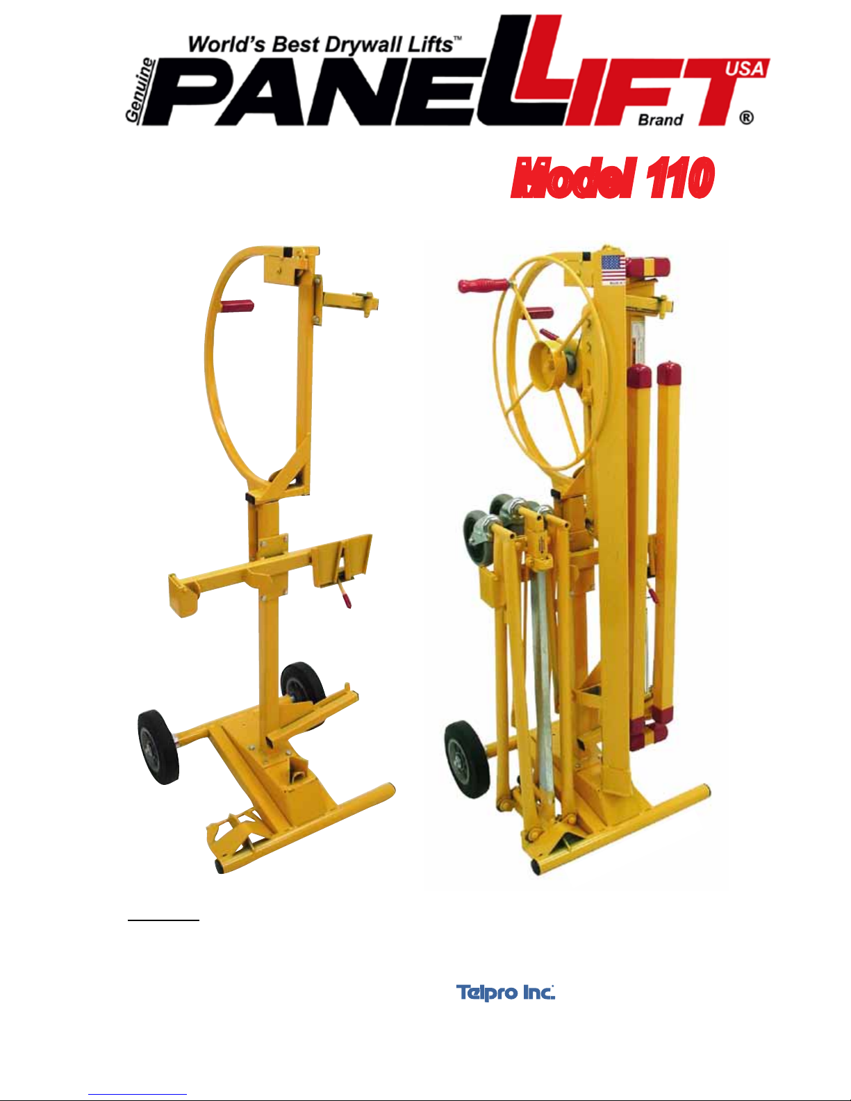
Drywall Lift Storage &
Patents Pending
Transportation Cart
Model 110
WARNING: When transporting, ALWAYS secure the PANELLIFT® Model 110 Drywall Lift Cart
in the vehicle to prevent shifting of the load while in transit. An unsecured load can shift,
possibly resulting in property damage and/or personal injury.
7251 S 42nd St • Grand Forks, ND • 58201
Form 42-44-00-00 Version 3
Unloaded
Made in U.S.A by
701-775-0551
www.worldsbestequipment.com
Loaded
© 2010 Telpro Inc. All Rights Reserved
Page 2
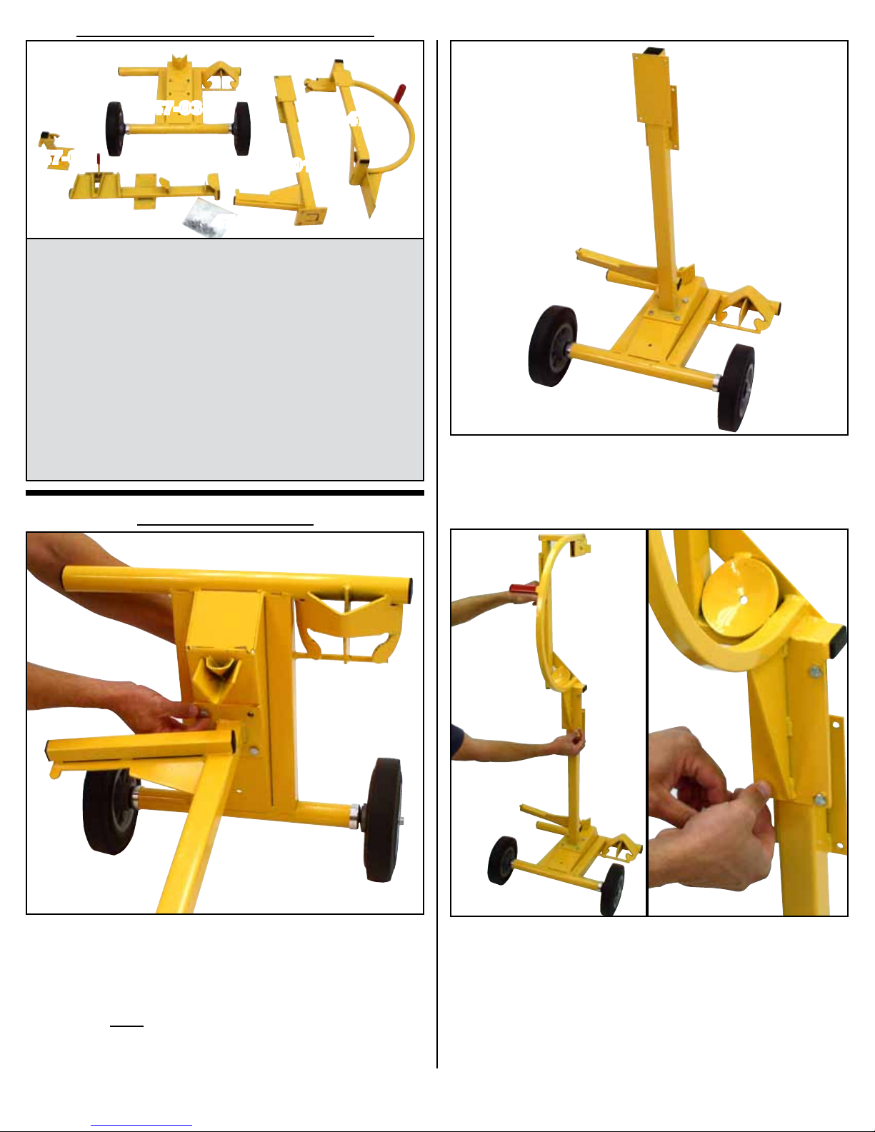
Complete Unit Consists Of:
47-03
47-05
47-01
47-02
47-06
47-00: Complete Upper Frame Section
47-01: Complete Mid Frame Section
47-02: Complete Cross Section
47-03: Complete Base Section
47-05: Upper Cradle Holder Assembly
47-06: Hardware Kit:
-1/4” X 1/2” Hex Bolt: 12
-1/4” Lock Nut: 12
-5/16” X 3/4” Hex Bolt: 4
-5/16” Lock Nut: 4
Initial Assembly
47-00
2. The photo above shows the Mid Frame Section correctly
oriented and attached to the Base Section.
1. Attach the Mid Frame Section to the Base Section using the
four 5/16” X 3/4” hex bolts and four 5/16” lock nuts provided.
IMPORTANT: Orient the Mid Frame Section in relation to the
Base Section as shown. The lower arm (“A” in the photo above)
must project away from the V strap (“B” in the photo above).
3. Attach the Upper Frame Section to the Mid Frame
Section as shown using four 1/4” X 1/2” hex bolts and four
1/4” lock nuts.
2
Page 3
A
Narrow ends of
tapered pockets
must be down
as shown.
Adjusting Upper Cradle Holder Assem.
After hand tightening the fasteners on the Upper Cradle
Holding Assembly you will need to adjust the Support to properly fit the Cradle of the PANELLIFT
stored there.
®
Model 138-2 that will be
A
B
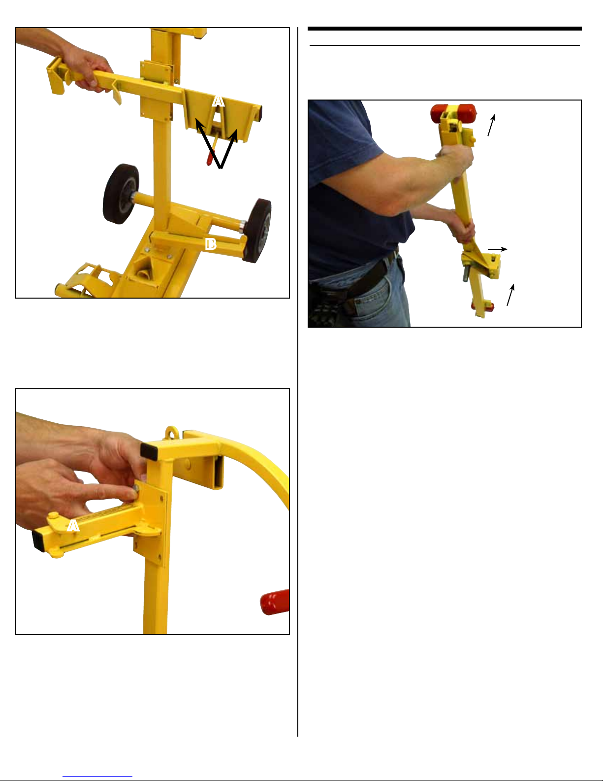
4. Attach the Cross Section to the Mid Frame Section as
shown using four 1/4” X 1/2” hex bolts and four 1/4” lock nuts.
Important: The Cross Section must be oriented as shown so
that the tapered Cross Arm storage pockets (“A” in the photo
above) are over the lower Cradle Support (“B” in the photo
above). The narrow ends of the pockets must be down.
A
B
A
6. Begin by taking up the Cradle and holding it oriented as
shown in the photo above with the tapered Cross Arm pockets (“A”) away from you and the Pivot Box (“B”) projecting to
your right.
5. Attach the Upper Cradle Holder Assembly to the Upper
Frame Section as shown using four 1/4” X 1/2” hex bolts and
four 1/4” lock nuts.
Important: The Upper Cradle Holder Assembly must be
oriented as shown so that the retaining catch (“A” in the photo
above) is up and the support angles down.
Tighten the fasteners only finger tight at this point.
3
Page 4
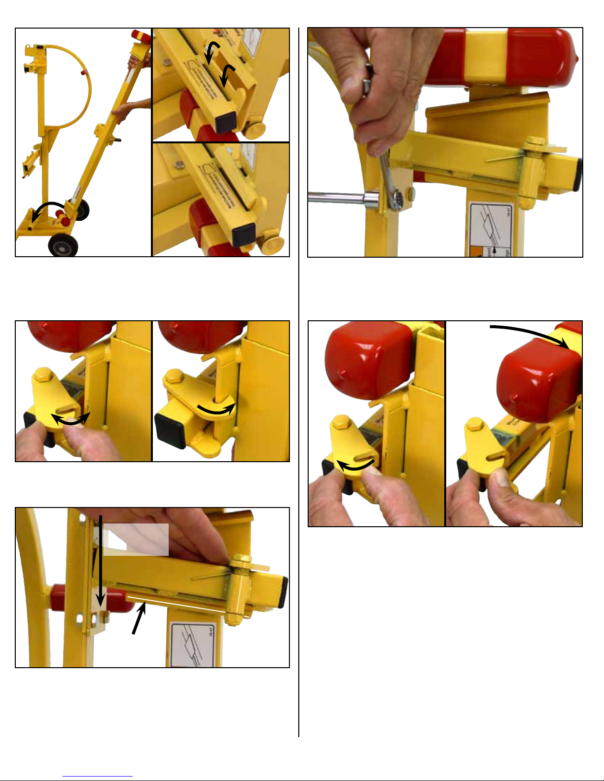
7. Mount the lower tapered Cross Arm pocket on the Lower
Cradle Support as shown above. The narrow end of the Cross
Arm pocket should face to the right toward the center of the
storage cart.
8. Secure the upper Cross Arm pocket of the Cradle behind the
spring latch on the Upper Cradle Support.
10. Securely tighten the bolt/lock nut assembly. Start with the
lower bolts to minimize movement of the Upper Cradle Support
Arm while tightening.
Slide Upper
Cradle Support
Bracket Down
Contact point
along this edge.
9. Slide the Upper Cradle support down on its slotted mounting
holes until it makes contact with the edge of the tapered Cross
Arm pocket on the Cradle. Due to variances in material, the
contact point may be anywhere along the edge of the Cross
Arm Pocket.
11. Check for a proper fit by opening the spring latch on the
Upper Cradle Support and tilting the top of the Cradle away.
The Cradle should move freely away without binding on the
Upper Cradle Support and it should also remain securely in
place when latched into the closed storage position. If adjustment is required, loosen the bolts and adjust as needed
4
Page 5
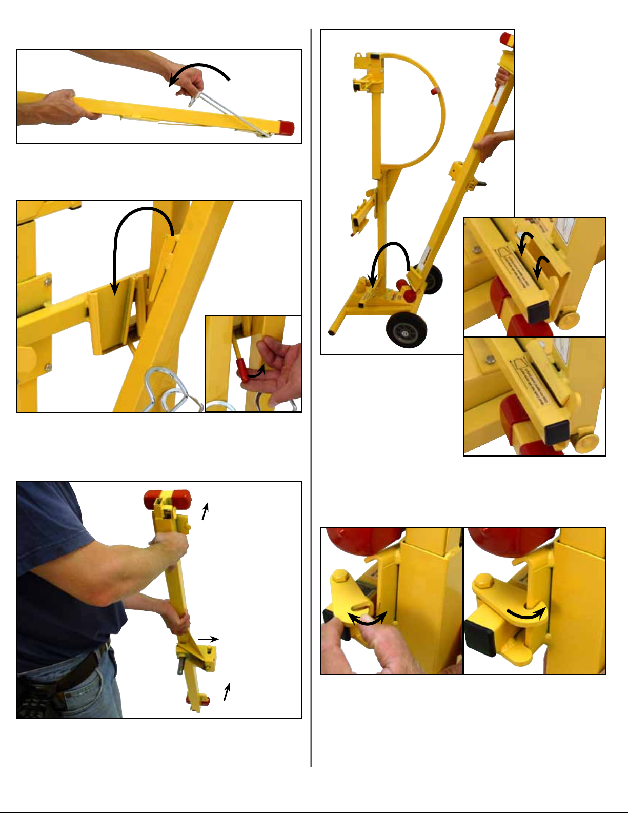
Loading the PANELLIFT® Model
138-2 Drywall Lift onto the Cart
12. Begin with the Cross Arms. Fold the Support Hook back-
wards. This will prevent it from rubbing on the other components when the Cross Arm is stored.
13. Insert the Cross Arm fully into the tapered pocket on the
Cross Section until the spring tab on the Cross Arm locks into
place. To remove, depress the Cross Arm spring tabs either
directly or using the release arm provided.
A
B
A
15. Mount the lower tapered Cross Arm pocket on the Lower
Cradle Support as shown above. The narrow end of the Cross
Arm pocket should face to the right toward the center of the
storage cart.
16. Secure the upper Cross Arm pocket of the Cradle behind
the spring latch on the Upper Cradle Support.
14. To load the Cradle, begin by holding it oriented as shown
in the photo above with the tapered Cross Arm pockets (“A”)
away from you and the Pivot Box (“B”) projecting to your right.
5
Page 6
A
C
A
B
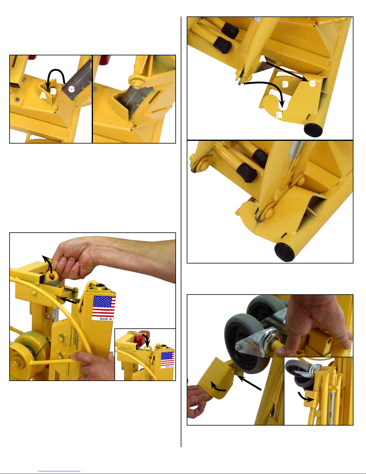
18. To load the Frame Assembly, start by mounting the foot of
the Frame on the cart Base Section as shown. Angle “C” fits
OVER angle “B” and inside angle “A”.
D
E
B
C
19. Lift up on the Frame Section Retaining Latch and tip
the Frame Section into the locking position. Make sure the
Retaining Latch is firmly holding the Frame Section in place.
20. Store the Tripod Base Assembly as shown above. Angle
“A” inserts beneath angle “C” while sliding over ridge “B”. The
Outer leg hinge points “D” will drop down into notch “E”.
21. Lift the Tripod Retaining Latch and tip the Tripod base into
the locking position.
6
Page 7
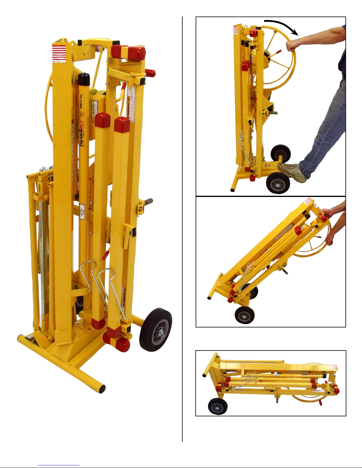
Your PANELLIFT® Model 138-2 is now securely loaded for convenient transportation or compact storage.
Handle the loaded PANELLIFT® Model 110 Drywall Lift
Cart as you would any two wheel material handling dolly.
When possible, transport the Loaded PANELLIFT®
Model 110 Drywall Lift Cart in the horizontal position
as shown. Always secure it with ropes or straps when
transporting to avoid tipping or moving of the load.
7
Page 8

Questions about assembly?
Can’t find a part?
Need some other help?
Call us:
1(800)448.0822
(701)775.0551
We’ll get you set up!
 Loading...