

Page 1
QUICK-START INSTALLATION GUIDE
TELOS INFINITY MP-16 AND DS-16
Digital Intercom Master Panel and Desk Station
INTRODUCTION
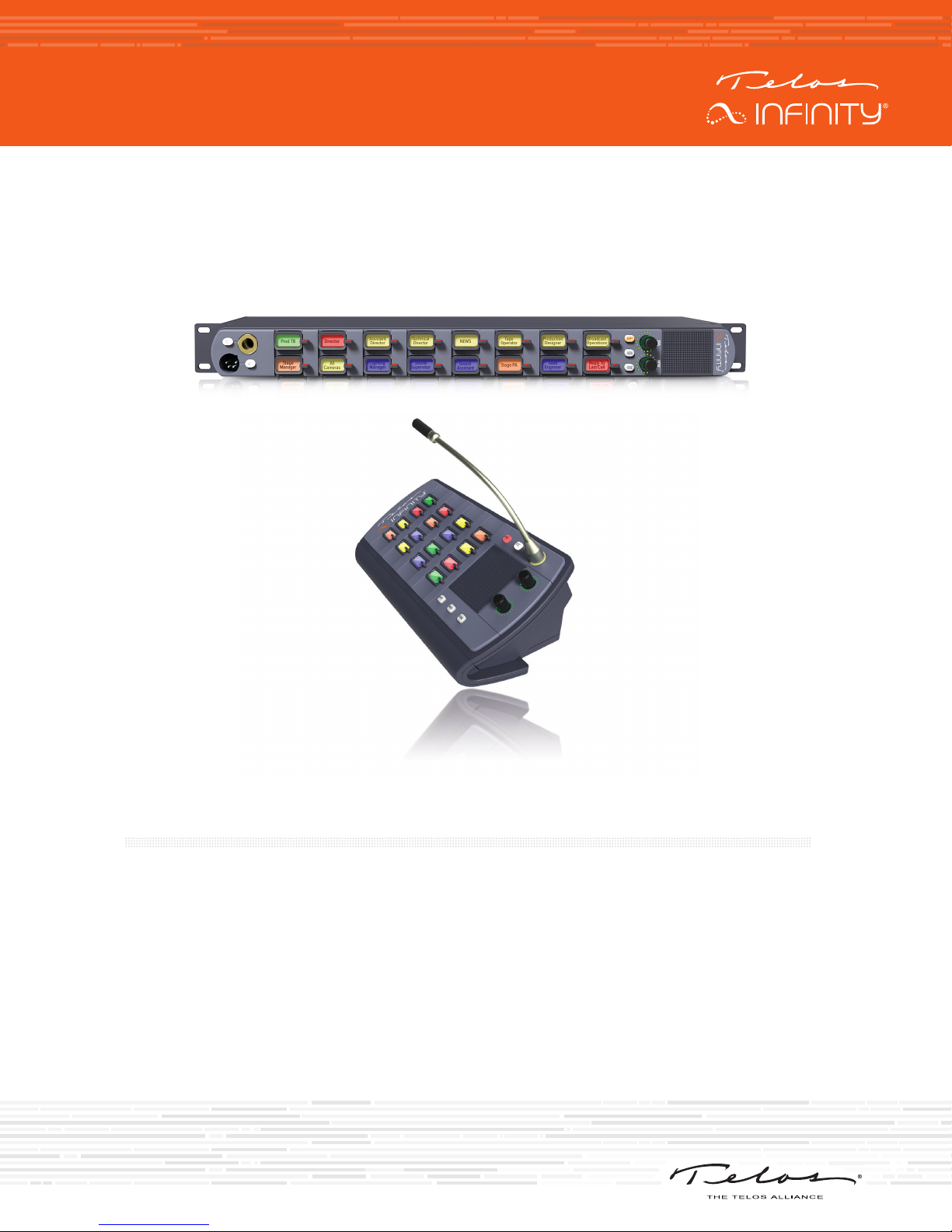
The INF-MP-16 and DS-16 are digital intercom panels designed to work as part of the Telos Infinity
‘matrix-free’ IP networked Intercom system. Telos Infinity supports all expected features such as pointto-point communications, groups, partylines, and IFBs.
The MP-16 and DS-16 connect over a supporting 1000Mbps Ethernet network with 24-bit/48 KHz
uncompressed digital audio carried as Audio over IP (AoIP) using the Livewire+™ AES67 industry standard.
Both panels are powered by PoE (Power over Ethernet) either directly from the network switch or via
an external PoE source. Additionally, a screw-lock 12VDC inlet is included on the rear panel, which may
be used as primary power if PoE is not available, or as part of a redundant power design (recommended
and encouraged).
Page 2
MP-16 AND DS-16 HARDWARE
HARDWARE
MP-16 Front Panel
A B
L K
DS-16 Front Panel
J
J HI
K
A
B
REAR
C D E F
G
L
I
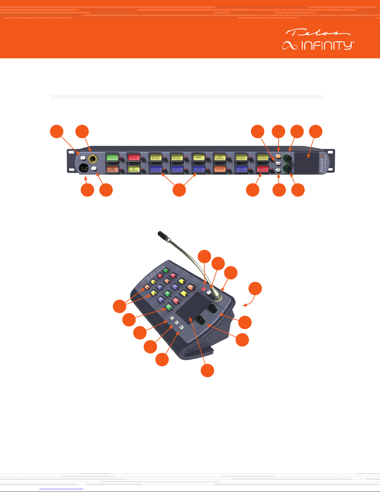
Mic Selection Switch (A)
Microphone Input (B)
A front panel socket supports an optional screw-in gooseneck microphone. The adjacent switch enables
or disables the front panel gooseneck microphone.
Menu Key (C)
The Menu Key puts the unit into Menu Mode. When operating in Menu mode, the Contact Keys change
function to display menu options and parameters, which are user-adjustable.
E
D
G
C
H
F
Page 3

MP-16 AND DS-16 HARDWARE
Shift Key (D)
The panel is capable of supporting more than 15 contacts. When more contacts are programmed to
the unit than it can display on the front panel at one time, the additional contacts may be grouped into
different layers, or Shift Pages. The Shift Key scrolls through the different Shift Pages (layers) of contacts,
only accessing pages that have been assigned a contact until finally returning to the first page at the end
of the cycle.
Main Output Volume Control (E)
The top rotary encoder on the unit provides the volume control function for the main output (either
the internal speaker, headset or the rear panel output when configured to output incoming talkback).
Rotating the encoder clockwise increases the volume. Rotating the encoder counter-clockwise decreases
the volume. Pushing the encoder in mutes/unmutes the listening function.
Internal Speaker (F)
An internal speaker is fitted within the panel, allowing the unit to be used without a headset. The speaker
is mounted into a sealed baffle, designed to optimize speech reproduction.
Aux Output Volume Control (G)
The bottom rotary encoder provides the volume control function for the Auxiliary output on the rear panel.
This functions in the same manner as the Main Output Volume Control described above.
Home Key (H)
The Home Key acts as an “escape” key and returns the unit to normal operating mode and to the 1st shift
page, from wherever the unit may be in the menu or shifted page structure.
Contact Keys (J)
Each of the contacts has its own key. Pressing the key down enables the Talk function and pressing the
key up enables the Listen function or answers an incoming call.
Last Caller Key (I)
The bottom right key of the unit displays the last contact that has called the panel and keeps a list of the
last 20 incoming callers received.
Headset Selection Switch (K)
Headset Input (L)
This male XLR connector will be either 4-pin (standard) or 5-pin (option), depending on how the unit
is ordered. The 4-pin XLR supports a single earmuff (mono) headset with microphone. The 5-pin XLR
supports a dual earmuff (dual mono or stereo) headset with microphone.
Note:
The panel automatically detects when a headset is connected and will change the
listening mode and microphone input to the headset instead of the internal speaker
and front panel gooseneck microphone input.
Page 4
MP-16 AND DS-16 HARDWARE
MP-16 Rear Panel
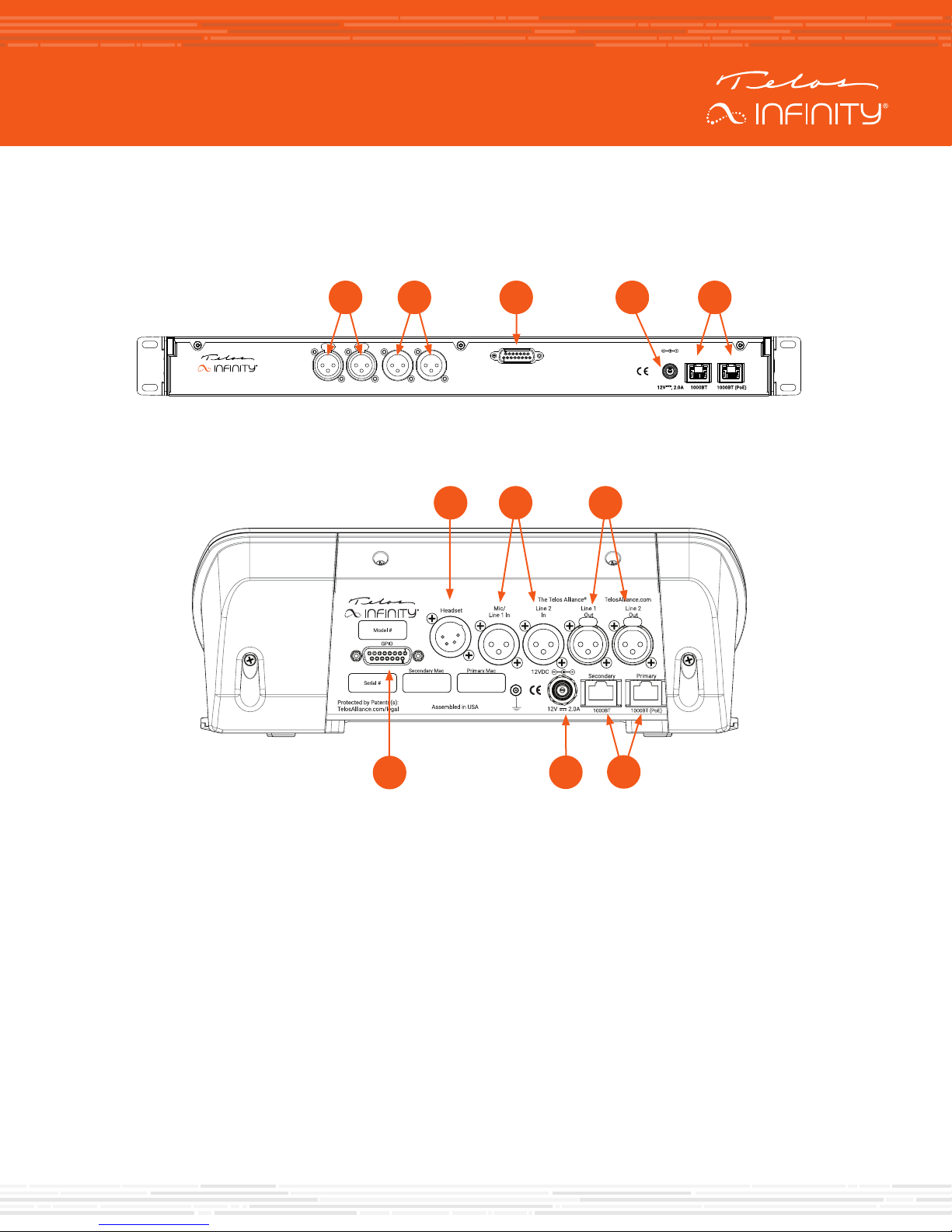
The rear panel of the unit comprises the following connectors:
B EC DA
INF-MP-16
DS-16 Rear Panel
Mic/
Line 1 In
Line 2
GPIO
Line 1
Line 2
Out
In
Out
F
C
BA
D
12VDC
E
PrimarySecondary
Analog Inputs (A)
Two female 3-pin XLR connectors are provided. They can be configured to accept either a mono
microphone input (left XLR only), or as a stereo line input. Phantom Power is supported when the input is
configured for microphone use.
Analog Line Outputs (B)
Two male 3-pin XLR connectors are included which provide a +4 dBu line level output. They can be
configured to output either an audio source, assigned from the Livewire+ AES67 network, or the talkback/
comms audio sent to the internal speaker. It is also possible to assign a combination of the two when the
external XLR connectors are set in dual mono mode.
GPIO (C)
A DB-15 socket connector provides 5 GPIO Inputs and 5 GPIO Output pins. The pinout is consistent with
other Telos Alliance products. GPIO connections are user-assignable.
Page 5

MP-16 AND DS-16 HARDWARE
DC Input (D)
A secure screw-lock +12 VDC input is included. This can be used to provide a redundant power source
(recommended) or primary power if a PoE source is not available.
Network Connections (E)
Two 1000-based T network connections are provided. One Ethernet port is for the input and PoE,
and the other port may be configured as a separate control or a network “through” for connecting to
Expansion Panels.
Headset Input (F)
This male XLR connector will be either 4-pin (standard) or 5-pin (option), depending on how the unit
is ordered. The 4-pin XLR supports a single earmuff (mono) headset with microphone. The 5-pin XLR
supports a dual earmuff (dual mono or stereo) headset with microphone.
Page 6
BASIC OPERATION
BASIC OPERATION
Talking
To talk to a desired contact, simply press the lever on the contact key down in the “Talk” direction. The Talk
key operates in one of two modes, depending on the assigned user action:
• Momentary (also called “Push to Talk”): Press and hold the Talk key for longer than ½ of a second. The
talk function will be enabled (on) as long as the Talk key is pressed. As soon as the Talk key is released,
the talk function will be disabled.
• Latched: Pressing the Talk key quickly (less than ½ of a second) will latch the talk function on. Pressing
the Talk key again will disable the talk function.
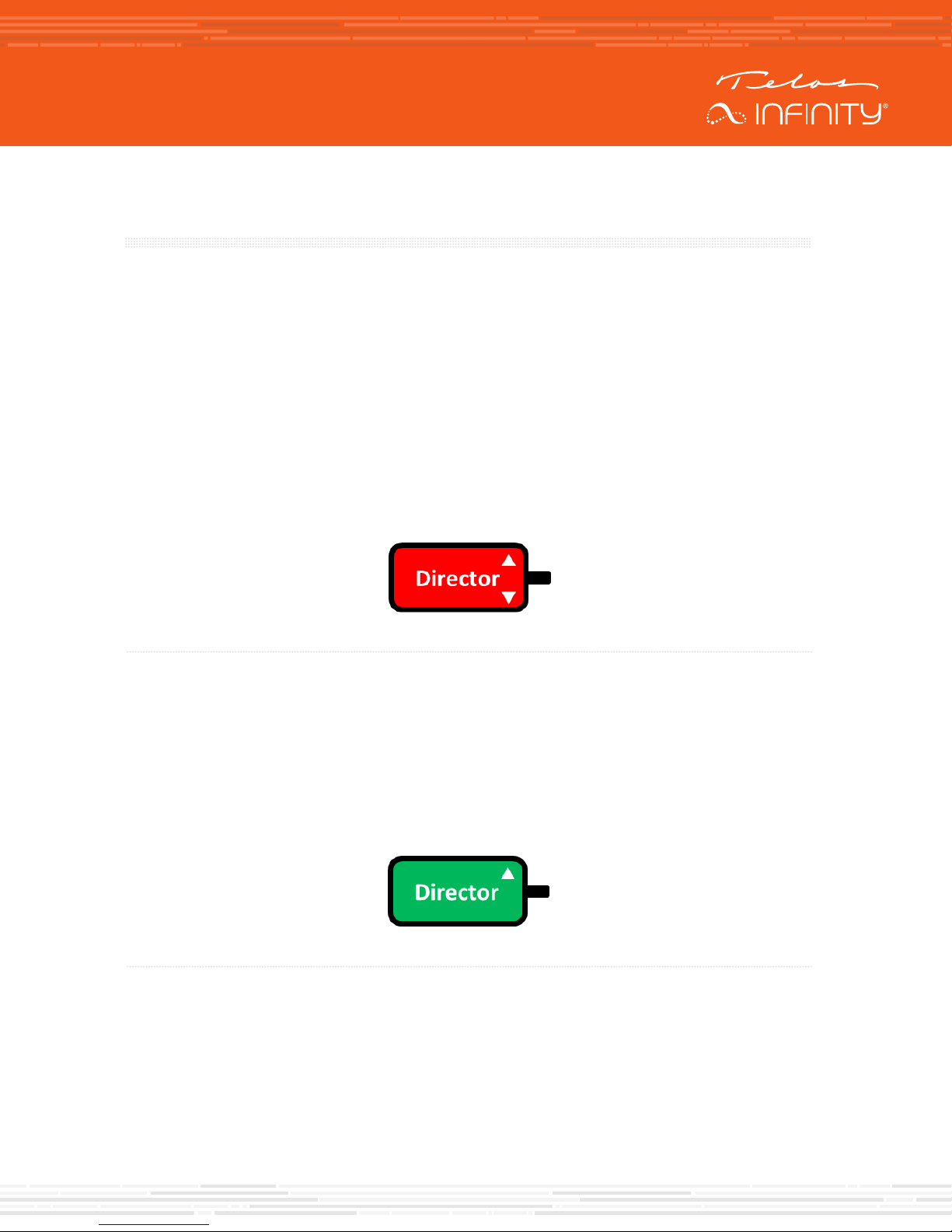
When the Talk function is active, the contact key display turns red and displays either a talk arrow, or Talk
LED located next to that channel’s Talk key will be lit.
Figure 1 - Talk + Auto Listen key type with the Talk Function active
Listening
By default, incoming calls are automatically answered, and the caller’s audio is heard without any user
interaction. However, it is possible to configure contact keys to simply signal an incoming call request and
make the user manually answer the call (much like a telephone call).
When an incoming call is received, the contact’s key will blink green for 3 seconds and will light solid green
for as long as the listen function is active.
Figure 2 - Example indication of listening to the Director
Page 7

BASIC OPERATION
Adjusting the Main Listening Volume
To adjust the listening volume of the headset, internal speaker, or rear panel output (main output
signal), rotate the Main Output volume control, the top encoder.
Turn the volume control clockwise (to the right) to increase the volume. Turn the volume control
counter-clockwise (to the left) to decrease the listening volume. Press the encoder to mute or unmute
the output. The LEDs around the encoder flash when muted.
Adjusting the Listening Volume of an Individual Contact
The listening level for each individual contact may be adjusted in the overall “mix” of contacts that is
listened to. To adjust the listening level for an individual contact:
1. Press and hold the contact key up in the listen (up) direction
2. Rotate the main volume encoder to the desired level while holding the contact key up in the
listen direction
3. A volume indicator graphic will appear on the contact key while adjusting mix level
Adjusting the Rear Panel Analog Output Listening Volume
To adjust the listening level of the rear panel Aux audio output (Aux audio), rotate the bottom encoder.
This encoder functions the same as the Main Output Volume Control located directly above it.
Page 8
CONFIGURATION
CONFIGURATION
Because the requirements and configurations for every intercom system are unique, the MP-16 and
DS-16 ship from the factory completely un-programmed. They are preconfigured for use with DHC
server–equipped networks. This means that before the units are ready to be used, they must be
configured and programmed appropriately. There are several methods available for accomplishing this.
The most intuitive and quickest method using the Dashboard application is described here. Please refer
to the MP-16 / DS-16 User Guide for an in-depth description of the alternate methods.
Dashboard
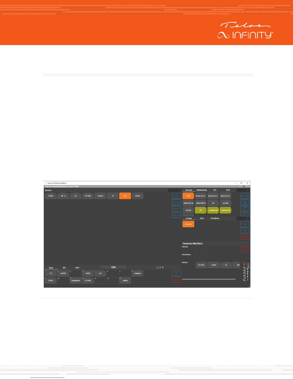
The easiest method of configuring Infinity Intercom systems and programming MP-16 / DS-16 devices
is to use the Dashboard application running on a Windows™ PC.
Dashboard automatically scans the network for Infinity devices and other Livewire+ AES67 audio
sources and destinations, such as Telos Alliance xNodes or Axia Broadcast Mixing Consoles.
Figure 3 - Example Dashboard screen
Page 9
CONFIGURATION
A
B
C
DE
F
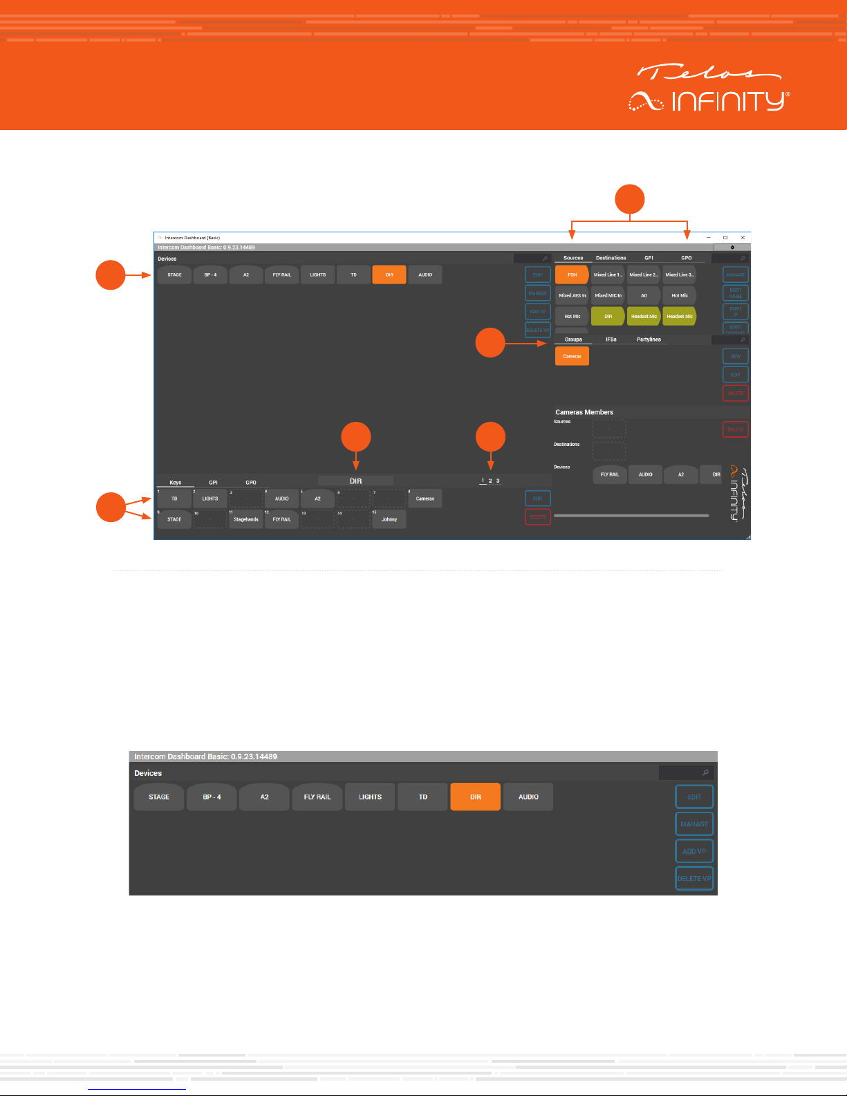
Figure 4 - Anatomy of the Dashboard Screen
Figure 4
(A) Infinity Intercom Devices, (B) Livewire+ Source / Destination and GPI/ GPO,
(C) Groups/IFB/Partyline configuration, (D) Shift Page Selection, (E) Panel Name, (F) Panel Keys
To configure the MP-16 or DS-16:
Click on the device to be configured.
To set the IP Configuration, click on the “Manage” button.
The device’s webpage will open in your computers default web browser.
Default login in details are:
User Name = user
Password = (no password)
Page 10
CONFIGURATION
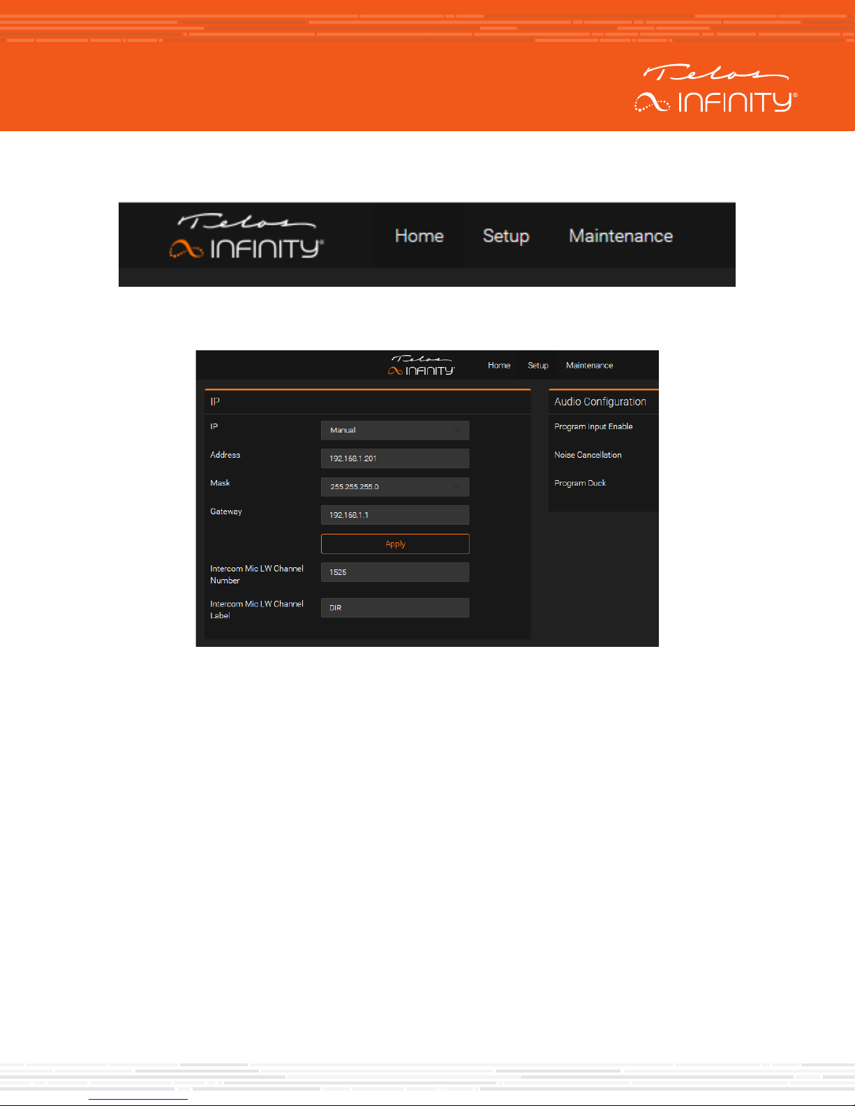
Once at the unit’s Home page, select the “Setup” tab
Once on the Setup page, configure the IP settings as desired, but be sure to press “Apply” once you are
satisfied with the changes selected.
Return to Dashboard once the IP settings are correct. If using Dashboard Basic, it may be necessary
to close and reopen the application so that it rescans the network for any updates that may have
been made.
To program keys, simply drag the device desired on to the appropriate Panel (contact) Keys in the
bottom left portion of the Dashboard window. Groups, Partylines, and IFBs can be assigned to keys
as well, simply by dragging and dropping them on to a key. Creating Groups, Partylines, and IFBs is
described below.
Panel Keys
Key Allocation
Panel Keys communicate to connected endpoints using one of the following allocations:
• Peer to Peer (Panel to Panel/BP)
• Group
• Partyline
• IFB
• Virtual Port
• Source (Listen Only)
Page 11
CONFIGURATION
Key Type
There are five types of key that can be allocated to Telos Infinity panel contact keys:
• Talk + Auto Listen
• Force Listener
• Talk Only
• Listen Only
• Disabled
When programming a panel, all Peer to Peer, Group, Partyline, IFB and Virtual Port keys will default
to Talk + Auto Listen. This mode ensures that all keys have bi-directional communication with the
associated peers and members. It also enables the listener to switch off their ‘listen’ function if they
choose. The Force Listener key is assigned to a Talker key when the use case seeks to prevent the
listener from turning their key off and missing an important call.
Creating a Virtual Port
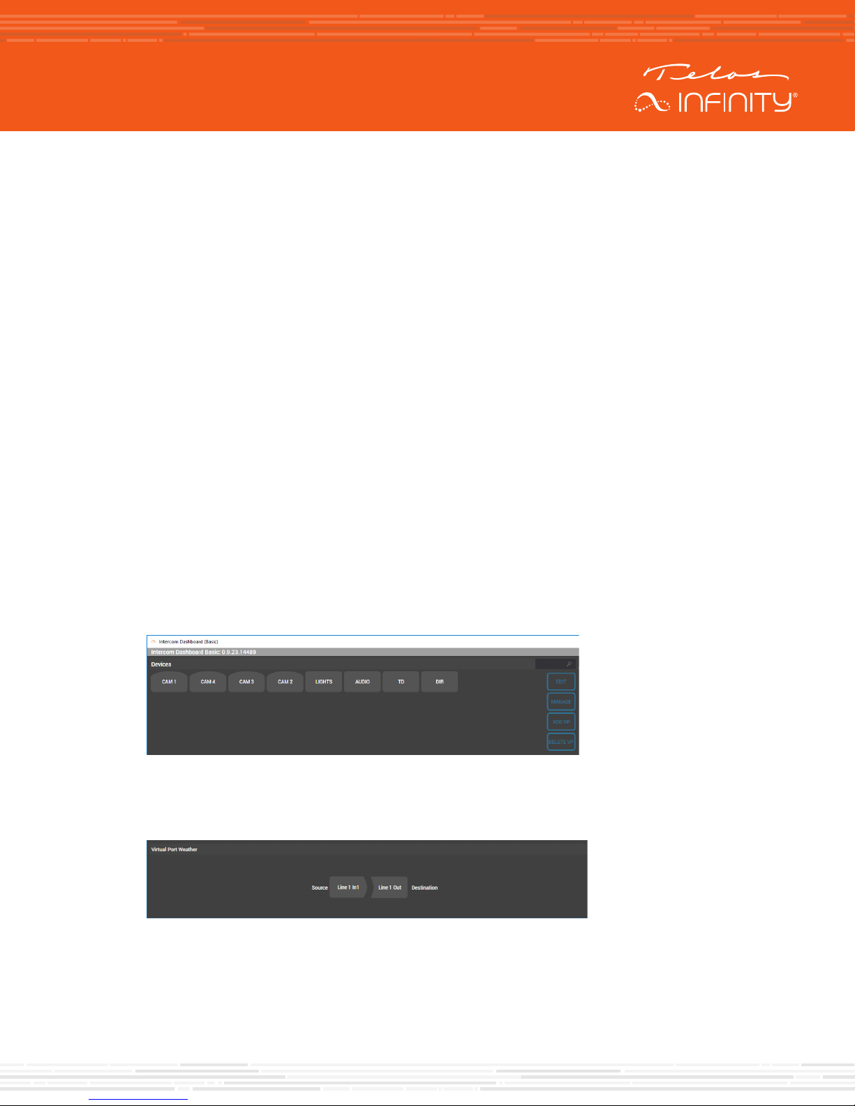
A Virtual Port (VP) allows for other audio sources and destinations to be associated with a contact.
A couple of examples of where Virtual Ports may be used are:
• RF microphone input via an xNode.
• xNode output to feed a powered speaker.
To create a Virtual Port:
• In the “devices” window, click on “ADD VP”
• Name the Virtual Port, press “OK”
• Select the Virtual Port
• Drag and drop the desired source and destination on the Source and Destination for the Virtual Port
`
Page 12
CONFIGURATION
Creating a Group or a Partyline
The process of creating either a Group or a Partyline is the same, though the inner workings of groups
and partylines are slightly different.1 Because the process for creating them is the same, only the
process of creating a Group will be described.
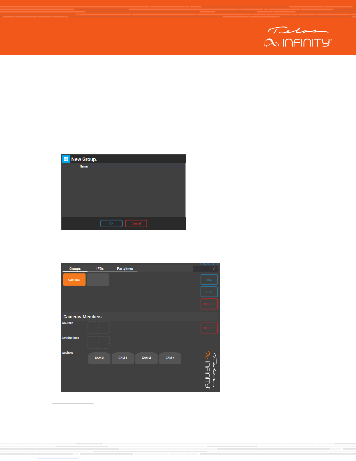
To create a group:
• Click on “Groups:
• Press “New”
• Name the Group and click on “OK”
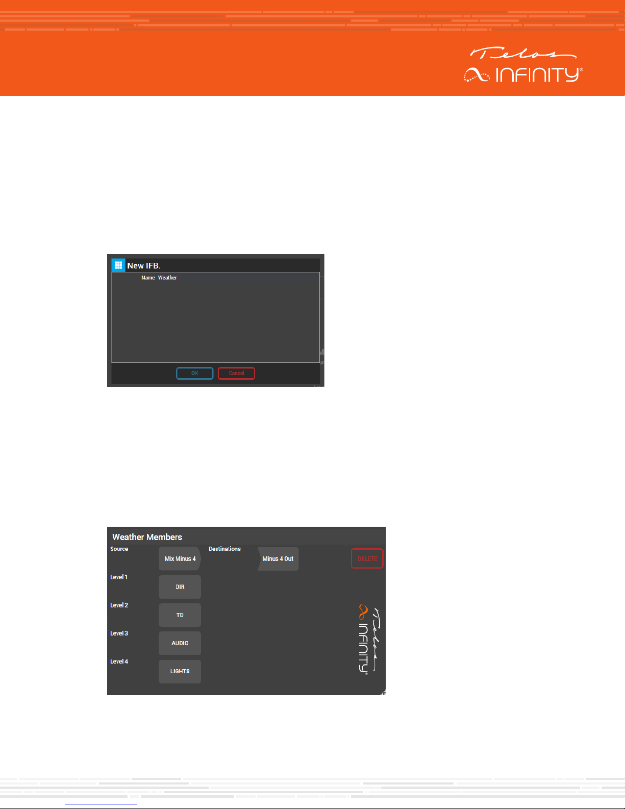
• To add members to the group, drag and drop the devices that are desired to be in the group on to
the “devices” section in the “members” area. The example below includes adding 4 camera belt
packs to the Cameras group
1 Groups allow those outside of the group to talk and listen to members of the Group, whereas Partylines allow everyone to hear and talk to each
other. For further explanation, refer to the MP-16’s owner’s manual.
Page 13
CONFIGURATION
To add a Group, or Partyline to a Panel’s contact key, drag and drop the Group or Partyline on to the
desired contact key.
Creating an IFB
To create an IFB:
• Click on “IFBs:
• Press “New”
• Name the IFB and click on “OK” (in this example, the IFB is named “Weather”)
• Drag and drop the appropriate contribution source (on-air talent’s microphone input) to the IFB
“Reverse Source”.
• Drag and drop the desired IFB signal source (typically a mix minus output of a mixing console) on to
the “Source” in the IFB Member’s area.
• Drag and drop the desired IFB output destination (often a device like the output from an xNode) on
to the Destination in the IFB Member’s area.
• Add interrupters by dragging and dropping contacts on the Level squares in the desired level in the
IFB Member’s area. Level 1 is the highest priority level of interrupter.
Page 14
CONFIGURATION
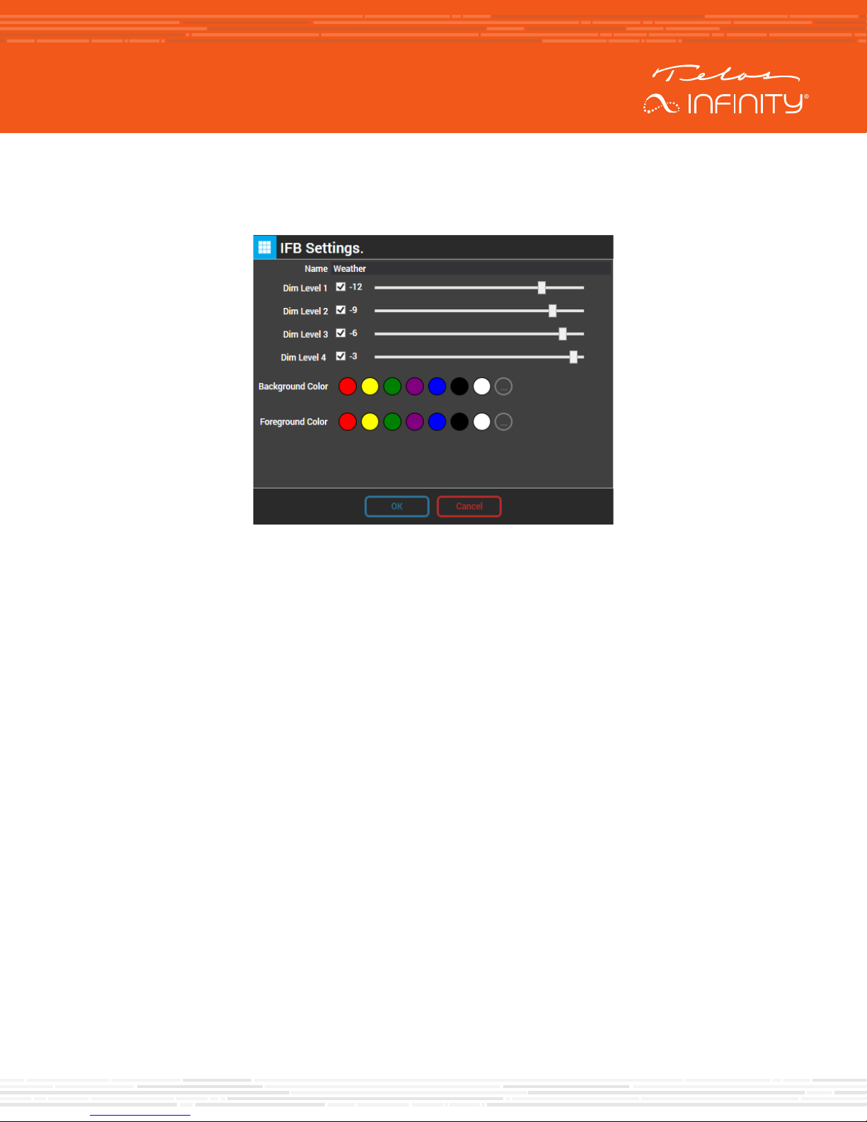
The amount that the program source signal is attenuated when an interrupter is talking to the IFB is
adjustable. To adjust the dim level, or attenuation, level, select the “Edit” in the zone where the IFB was
initially created. To use an adjustable dim level, ensure that “Dim Level” is checked. If unchecked, the
program source audio is completely muted when an interrupter is talking.
To add an IFB to a Panel’s contact key, drag and drop the IFB on to the desired contact key.
Page 15

QUICK-START INSTALLATION GUIDE
This Page Intentionally Left Blank
Page 16
QUICK-START INSTALLATION GUIDE
QUICK LINKS
Subscribe to DirectCurrent
Weekly updates on all things broadcast via email
TelosAlliance.com/directcurrent
Social Media
Facebook: /TelosAlliance
Twitter: @TelosAlliance
LinkedIn: /TelosAlliance
YouTube: TelosAllianceTV
Google+: +TelosAlliance
Product Catalog
TelosAlliance.com/now
24/7 Tech Support
Radio: +1 (216) 622-0247
TV: +1 (717) 735-3611
Radio: [email protected]
1241 Superior Ave. • Cleveland, Ohio, 44114, USA • +1.216.241.7225 • TelosAlliance.com
© 2019 TLS Corp. The Telos Alliance®. All Rights Reserved. C19/1/17033 PN: 1490-00208-001 --- QUICK START GUIDE: MP-16 & DS-16
 Loading...