

TELOS INFINITY MP-16, DS-16 Quick Start Installation Manual
QUICK-START INSTALLATION GUIDE
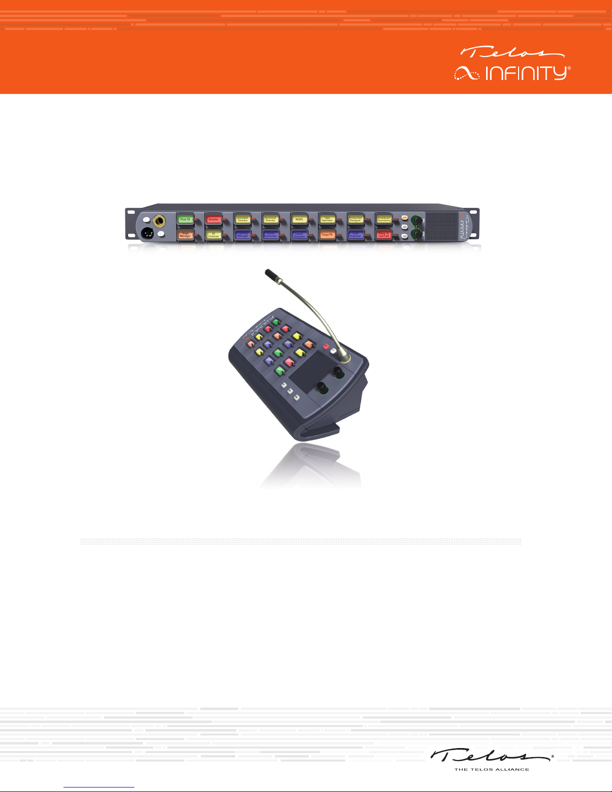
TELOS INFINITY MP-16 AND DS-16
Digital Intercom Master Panel and Desk Station
INTRODUCTION
The INF-MP-16 and DS-16 are digital intercom panels designed to work as part of the Telos Infinity
‘matrix-free’ IP networked Intercom system. Telos Infinity supports all expected features such as pointto-point communications, groups, partylines, and IFBs.
The MP-16 and DS-16 connect over a supporting 1000Mbps Ethernet network with 24-bit/48 KHz
uncompressed digital audio carried as Audio over IP (AoIP) using the Livewire+™ AES67 industry standard.
Both panels are powered by PoE (Power over Ethernet) either directly from the network switch or via
an external PoE source. Additionally, a screw-lock 12VDC inlet is included on the rear panel, which may
be used as primary power if PoE is not available, or as part of a redundant power design (recommended
and encouraged).
MP-16 AND DS-16 HARDWARE
HARDWARE
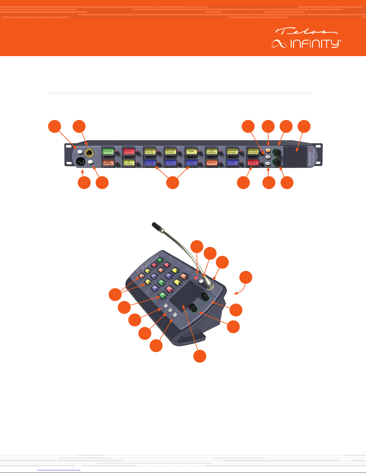
MP-16 Front Panel
A B
L K
DS-16 Front Panel
J
J HI
K
A
B
REAR
C D E F
G
L
I
Mic Selection Switch (A)
Microphone Input (B)
A front panel socket supports an optional screw-in gooseneck microphone. The adjacent switch enables
or disables the front panel gooseneck microphone.
Menu Key (C)
The Menu Key puts the unit into Menu Mode. When operating in Menu mode, the Contact Keys change
function to display menu options and parameters, which are user-adjustable.
E
D
G
C
H
F

MP-16 AND DS-16 HARDWARE
Shift Key (D)
The panel is capable of supporting more than 15 contacts. When more contacts are programmed to
the unit than it can display on the front panel at one time, the additional contacts may be grouped into
different layers, or Shift Pages. The Shift Key scrolls through the different Shift Pages (layers) of contacts,
only accessing pages that have been assigned a contact until finally returning to the first page at the end
of the cycle.
Main Output Volume Control (E)
The top rotary encoder on the unit provides the volume control function for the main output (either
the internal speaker, headset or the rear panel output when configured to output incoming talkback).
Rotating the encoder clockwise increases the volume. Rotating the encoder counter-clockwise decreases
the volume. Pushing the encoder in mutes/unmutes the listening function.
Internal Speaker (F)
An internal speaker is fitted within the panel, allowing the unit to be used without a headset. The speaker
is mounted into a sealed baffle, designed to optimize speech reproduction.
Aux Output Volume Control (G)
The bottom rotary encoder provides the volume control function for the Auxiliary output on the rear panel.
This functions in the same manner as the Main Output Volume Control described above.
Home Key (H)
The Home Key acts as an “escape” key and returns the unit to normal operating mode and to the 1st shift
page, from wherever the unit may be in the menu or shifted page structure.
Contact Keys (J)
Each of the contacts has its own key. Pressing the key down enables the Talk function and pressing the
key up enables the Listen function or answers an incoming call.
Last Caller Key (I)
The bottom right key of the unit displays the last contact that has called the panel and keeps a list of the
last 20 incoming callers received.
Headset Selection Switch (K)
Headset Input (L)
This male XLR connector will be either 4-pin (standard) or 5-pin (option), depending on how the unit
is ordered. The 4-pin XLR supports a single earmuff (mono) headset with microphone. The 5-pin XLR
supports a dual earmuff (dual mono or stereo) headset with microphone.
Note:
The panel automatically detects when a headset is connected and will change the
listening mode and microphone input to the headset instead of the internal speaker
and front panel gooseneck microphone input.
MP-16 AND DS-16 HARDWARE
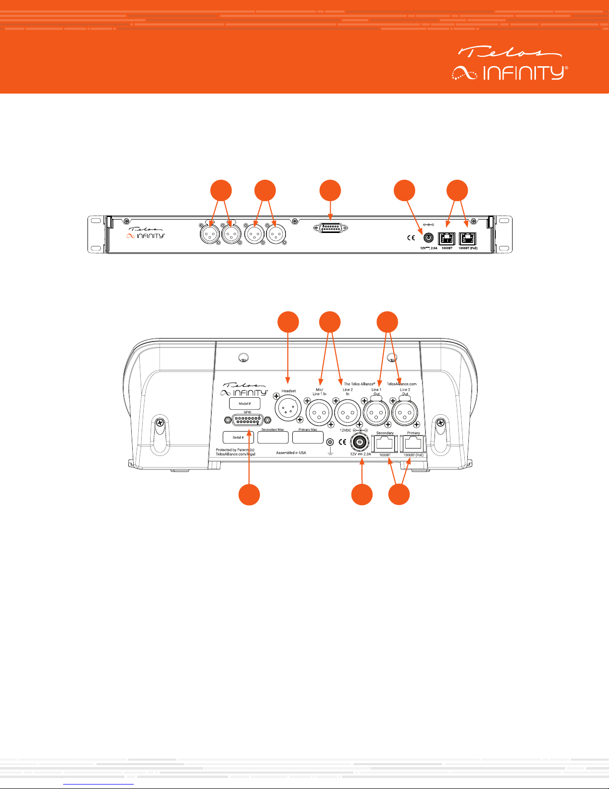
MP-16 Rear Panel
The rear panel of the unit comprises the following connectors:
B EC DA
INF-MP-16
DS-16 Rear Panel
Mic/
Line 1 In
Line 2
GPIO
Line 1
Line 2
Out
In
Out
F
C
BA
D
12VDC
E
PrimarySecondary
Analog Inputs (A)
Two female 3-pin XLR connectors are provided. They can be configured to accept either a mono
microphone input (left XLR only), or as a stereo line input. Phantom Power is supported when the input is
configured for microphone use.
Analog Line Outputs (B)
Two male 3-pin XLR connectors are included which provide a +4 dBu line level output. They can be
configured to output either an audio source, assigned from the Livewire+ AES67 network, or the talkback/
comms audio sent to the internal speaker. It is also possible to assign a combination of the two when the
external XLR connectors are set in dual mono mode.
GPIO (C)
A DB-15 socket connector provides 5 GPIO Inputs and 5 GPIO Output pins. The pinout is consistent with
other Telos Alliance products. GPIO connections are user-assignable.

MP-16 AND DS-16 HARDWARE
DC Input (D)
A secure screw-lock +12 VDC input is included. This can be used to provide a redundant power source
(recommended) or primary power if a PoE source is not available.
Network Connections (E)
Two 1000-based T network connections are provided. One Ethernet port is for the input and PoE,
and the other port may be configured as a separate control or a network “through” for connecting to
Expansion Panels.
Headset Input (F)
This male XLR connector will be either 4-pin (standard) or 5-pin (option), depending on how the unit
is ordered. The 4-pin XLR supports a single earmuff (mono) headset with microphone. The 5-pin XLR
supports a dual earmuff (dual mono or stereo) headset with microphone.
 Loading...