

Page 1
QUICK-START INSTALLATION GUIDE
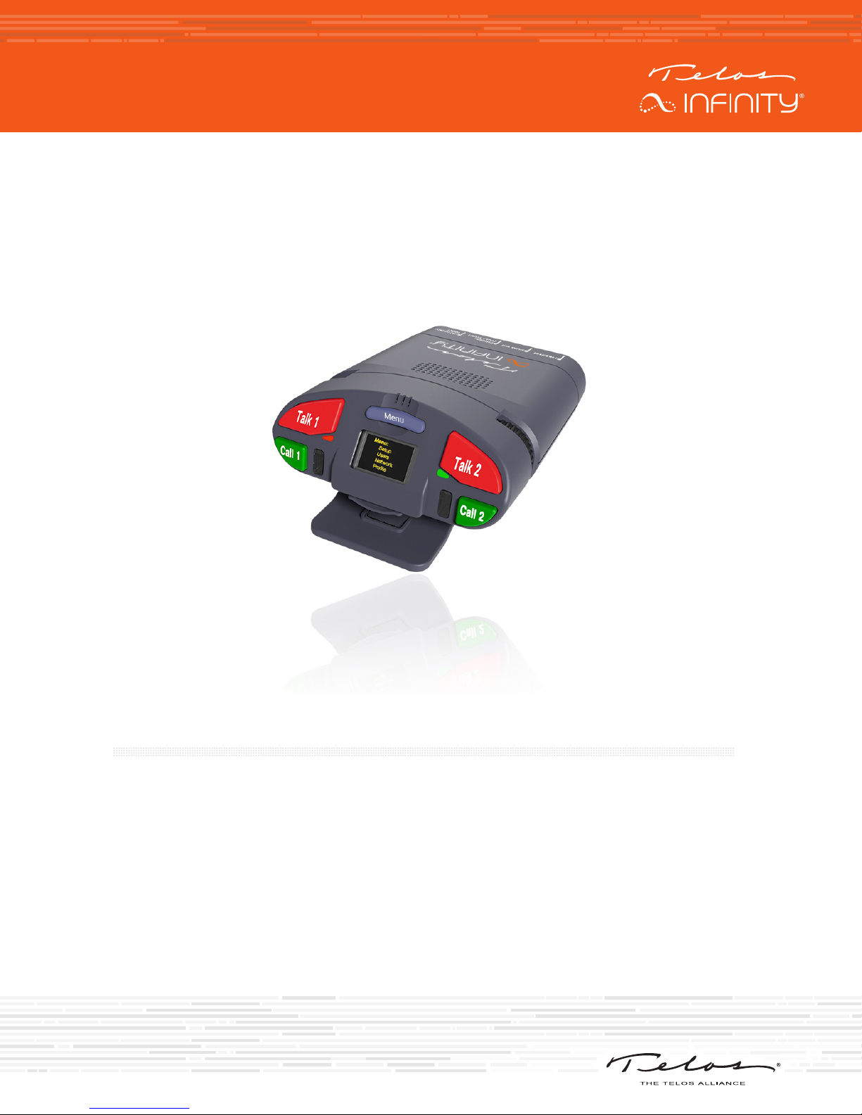
TELOS INFINITY BP-2
Digital Intercom Beltpack
INTRODUCTION
The INF-BP-2 is a dual communication channel digital Beltpack that includes the additional ability
to monitor an auxiliary program audio feed. Unlike traditional analog intercom beltpacks, each
communication channel may be configured to be part of a partyline, group, IFB, or a point to point contact
regardless of the physical connection of the device to the supporting network.
The BP-2 connects over a supporting 100Mbps Ethernet network with 24-bit/48 KHz uncompressed
digital audio carried as Audio over IP (AoIP) using the Livewire+® AES67 industry standard.
The BP-2 is powered by PoE (Power over Ethernet) either directly from the network switch or via an
external PoE source. Additionally, multiple BP-2 beltpacks may be daisy-chained from the network
switch to one another.
Page 2
HARDWARE
HARDWARE
Front Panel
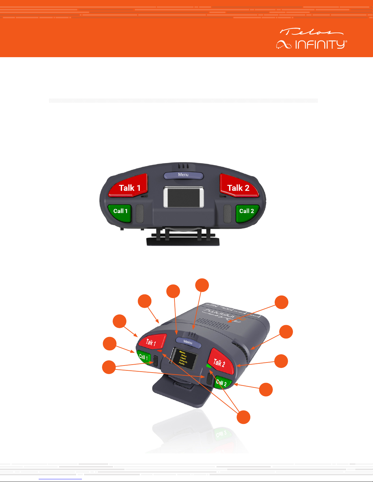
The front panel of the BP-2 intercom Beltpack includes a monochrome OLED display, two talk keys, two
call keys, a menu key, and a miniature condenser microphone. There are recessed volume controls for
Channel 1 and Channel 2 on the side of the unit near the front panel.
Controls
E
D
C
B
A
F
G
H
I
J
K
Page 3

HARDWARE
Call Indicators (A)
This indicator will light up when a Call message is received.
Call Keys (B, J)
Each channel includes a Call key which is available when either a partyline or a point to point contact is
assigned to a channel. Pressing this key will trigger a call message to other intercom devices assigned to
the same partyline, or the other point to point contact.
Talk Keys (C, I)
Each of the two channels has its own talk key. Pressing and holding the Talk key will activate a “press to
talk” function and the microphone will be muted when the Talk key is released. Pressing the talk key for
one second or less will latch the talk function on until the Talk key is pressed and released again.
Channel Volume Controls (D, H)
Each channel has its own volume control. The volume encoders are located on the side of the beltpack
just below where the keys. Rotating the encoder clockwise increases the volume, and rotating the
encoder counterclockwise decreases the volume. Volume encoders are also used to scroll through
parameters and values when the beltpack is operating in Menu Mode.
Menu Key (E)
The menu key toggles the BP-2 between normal operating mode and the Menu Mode. To enter the Menu
Mode, press and hold this key for 5 seconds. Similarly, to quickly exit the Menu mode and return to
normal operating mode, press and hold the Menu Key for 5 seconds.
Internal Microphone (F)
The BP-2 includes an internal condenser microphone and may be used without a headset if desired.
Internal Speaker (G)
The BP-2 includes an internal loudspeaker and may be used without a headset if desired. The internal
speaker allows the user to hear program audio, or audio from whomever is speaking to them.
Note!
The BP-2 automatically detects when a headset is connected and will change the
listening mode to headset instead of the internal speaker.
Talk Indicators (K)
Each channel includes a Talk indicator next to the Talk key which will light up when the Talk function
is enabled.
Page 4
HARDWARE
Rear Panel
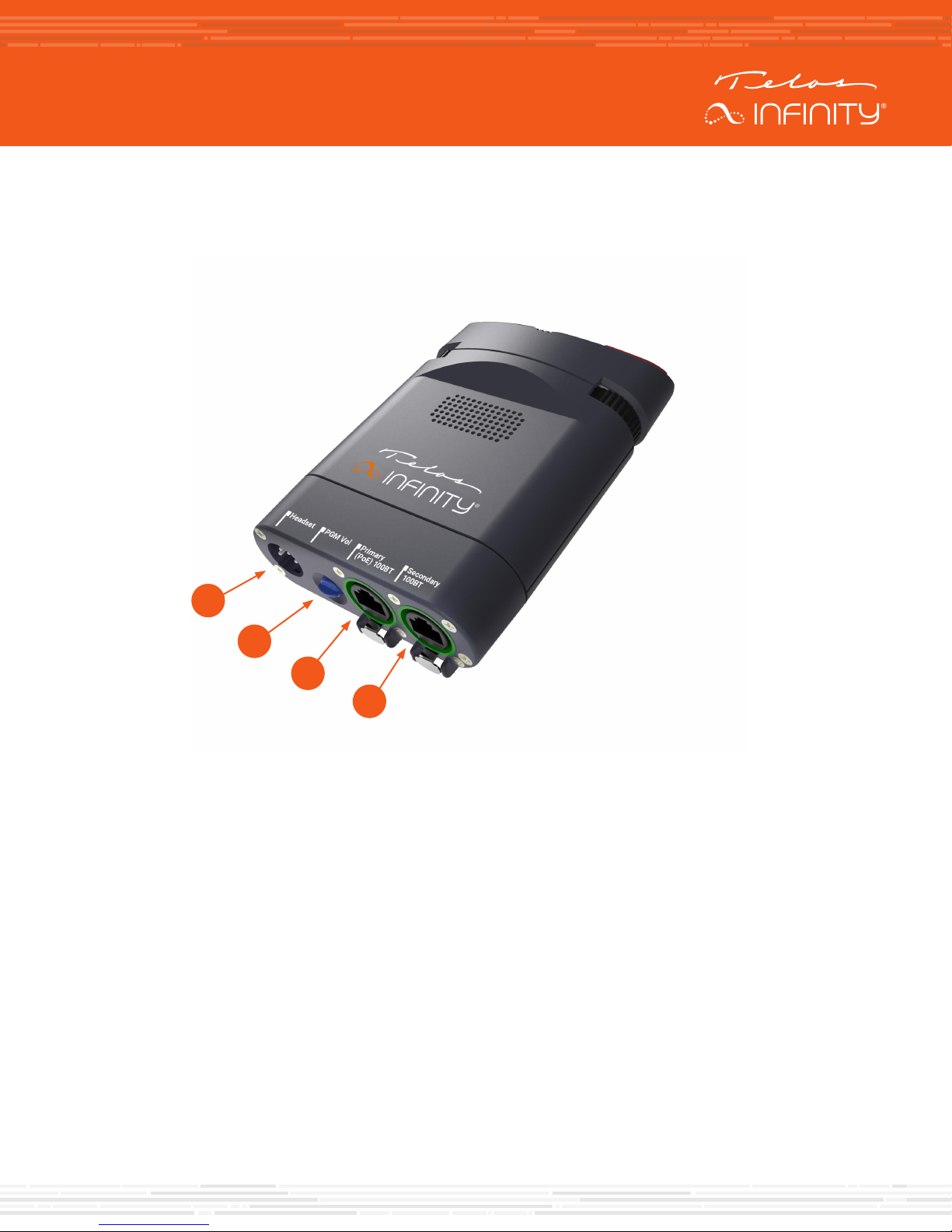
The rear panel of the BP-2 includes the following connectors:
A
B
C
D
Headset (A)
This male XLR connector will be either 4-pin (standard) or 5-pin (option), depending on how the unit
is ordered. The 4-pin XLR supports a single earmuff (mono) headset with microphone. The 5-pin XLR
supports a dual earmuff (dual mono or stereo) headset with microphone.
Program Input Volume control (B)
This encoder directly adjusts the listening volume of the Program Input audio.
Network Connections (C, D)
Two 100-based T network connections are provided. One ethernet port is marked ‘Primary’ for the input
(C), and the other port is a ‘Secondary’ network output (D) for daisy chaining beltpacks.
Note!
The BP-2 required Power over Ethernet (PoE) to operate. If the unit does not power
up, verify that PoE is available, and that the cable is plugged into the primary
connector.
Page 5

BASIC OPERATION
BASIC OPERATION
Talking
To talk to a desired channel, simply press the “Talk” key. The Talk key operates in one of two modes,
depending on the user’s action:
• Momentary (also called “Push to Talk”): Press and hold the Talk key for longer than 1 second. The talk
function will be enabled (on) if the Talk key is pressed. As soon as the Talk key is released, the talk
function will be disabled.
• Latched: Pressing the Talk key quickly (less than 1 second) will latch the talk function on. Pressing the
Talk key again will disable the talk function.
When the Talk function is active, the Talk LED located next to that channel’s Talk key will be lit.
Calling
To send a call signal to other members of a partyline, press the Call button. The Call LED will light on all
beltpacks of the partyline, including the beltpack which initiated the call signal.
Adjusting the Listening Volume
Each channel has its own individual volume control on the side of the beltpack.
To adjust the listening volume, turn the encoder on the side of the beltpack nearest to the channel.
• Turning the volume control in a clockwise direction (to the right) increases the volume.
• Turning the volume control in a counter-clockwise direction (to the left) decreases the listening
volume.
• To adjust the listening volume of the Program Input, adjust the volume encoder on the bottom of the
beltpack.
Page 6
MENU
MENU
Menu Mode
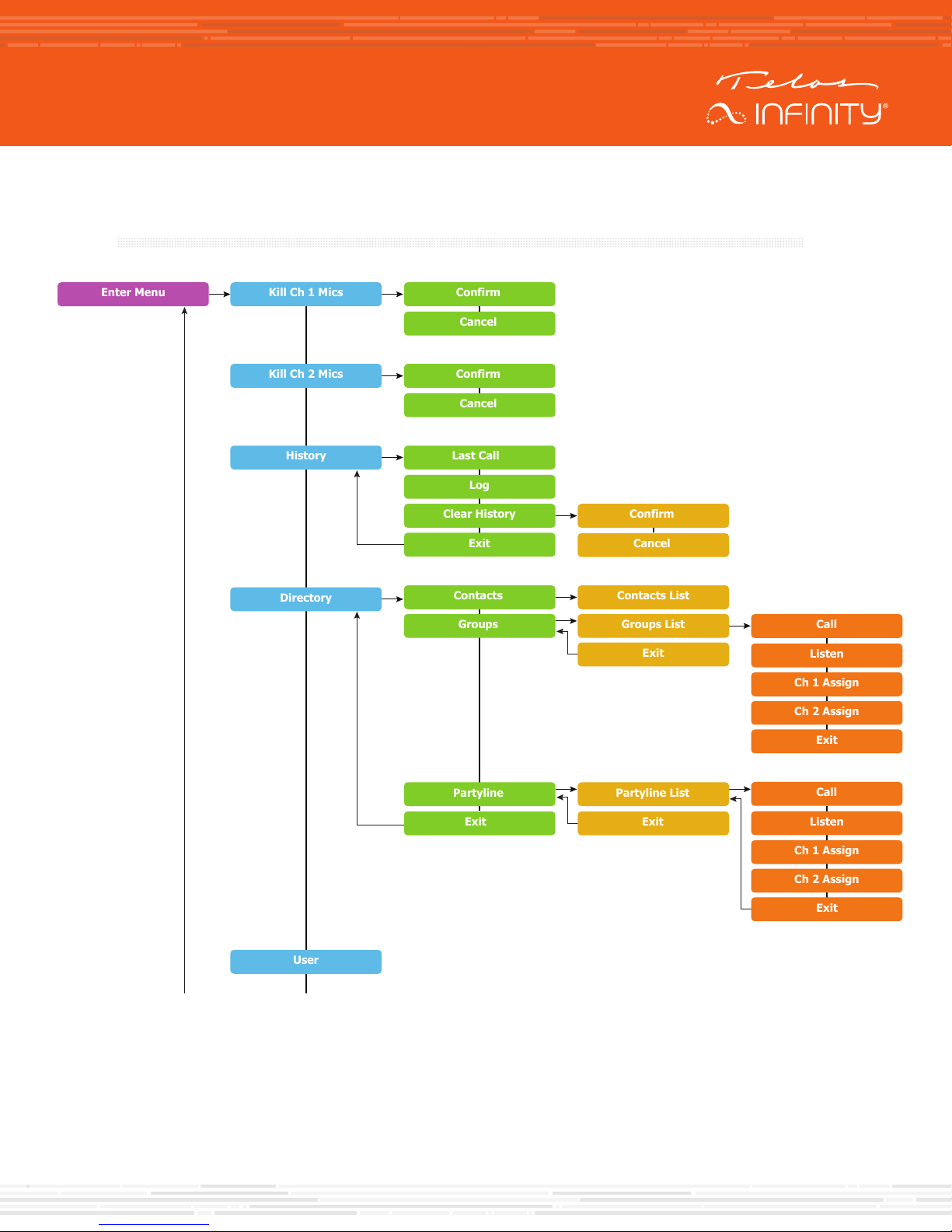
Menu Mode allows limited configuration changes to be made to the BP-2, though full configuration and
programming is best performed via the Dashboard application.
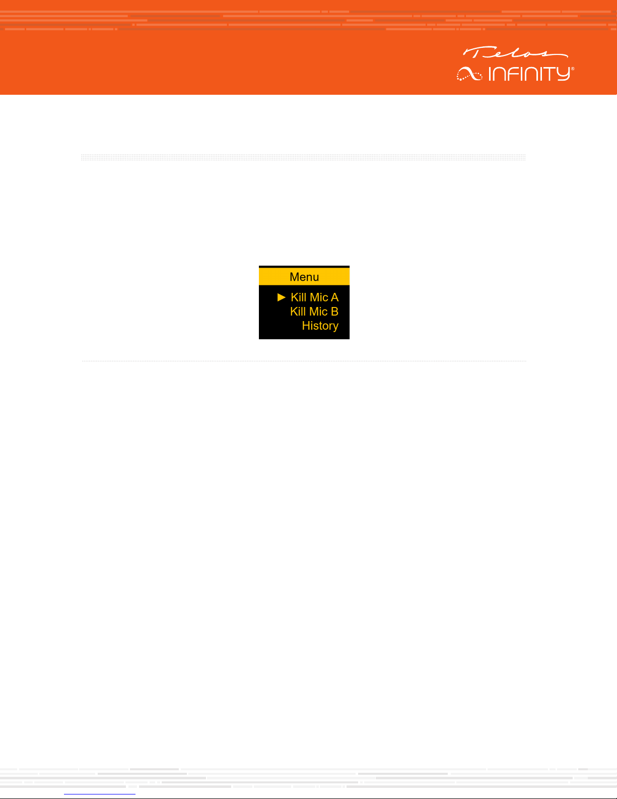
To enter Menu Mode, press and hold the “Menu” key for 5 seconds. While the unit is in Menu Mode, the
top of the display will display “Menu”.
Figure 1 - Menu Mode display
To exit the Menu Mode, either repeatedly select the “exit” option in each menu until the unit is returned to
normal operating mode, or simply press and hold the Menu key again for 5 seconds
To navigate the menu structure:
• Rotate the Ch 2 volume encoder to scroll through the menu, parameters, and adjust the values.
• Press the Menu key to accept, or “take”, the change in parameter or selection.
2018 TLS Corp., All Rights Reserved. C16/17013 1490-00159-001 — QUICK START GUIDE: Infinity MPX20
©
Page 7
USE CASES
USE CASES
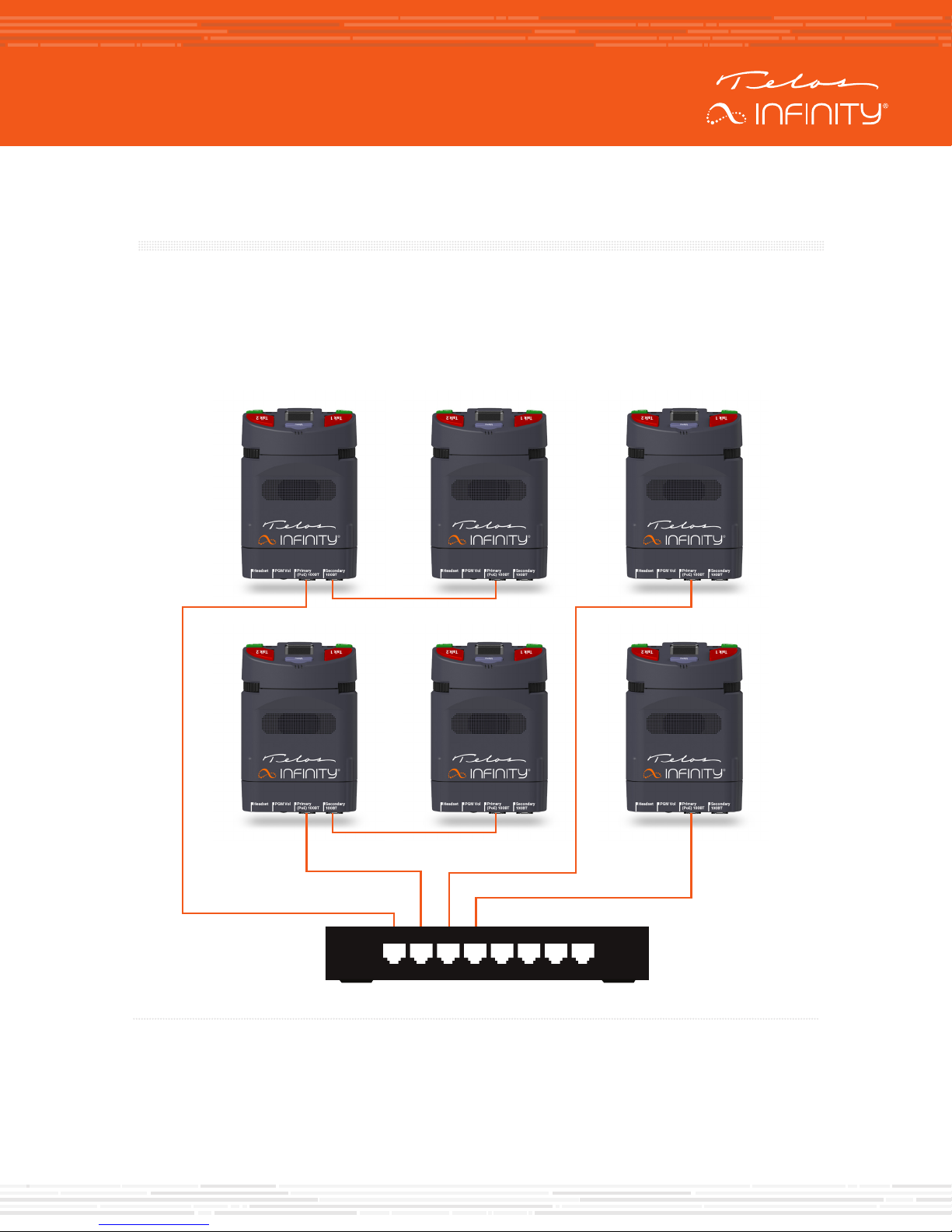
Basic 2-channel Party Line system
The BP-2 ships from the factory pre-configured for a 2-channel Party Line system. To use a 2-channel
Party Line system, simply plug the beltpacks into an Ethernet switch that includes DHCP server
capability and supplies Power over Ethernet (PoE). It’s that simple!
Figure 2 – Basic 2 channel Party Line System
Page 8

USE CASES
To configure the unit for a fixed IP address
If a switch that includes a DHCP server is not available, then the BP-2 units must be configured for
fixed, or static, IP addresses. The simplest way to accomplish this is to use the unit’s webpage. This
can be either access via the Dashboard control application, or directly if you know the address of the
beltpack.
The default login details are:
• Username: user
• Password: <no password, simply press “Enter”>
Alternatively, the unit may be configured via the front panel controls. To configure the IP settings for
the beltpack:
• Press and hold the menu button for 5 seconds to enter the Menu mode
• Rotate the Ch1 volume encoder until “setup” is highlighted
• Press Menu to enter Setup menu
• Rotate the Ch 1 encoder until “Beltpack” is highlighted
• Press Menu to enter the Beltpack submenu
• Rotate the Ch1 encoder until IP Address is highlighted
• Press Menu to enter the IP Address submenu
• Select the unit to use a Fixed IP address instead of DHCP
• To set the IP address, rotate the Ch2 encoder to set the digit value, press Menu to accept the
number and move to the next digit place
“Unit ID” allows the naming of the beltpack to something easily understandable, such as “Audio”,
“Director”, CAM 1”, etc.
Page 9
USE CASES
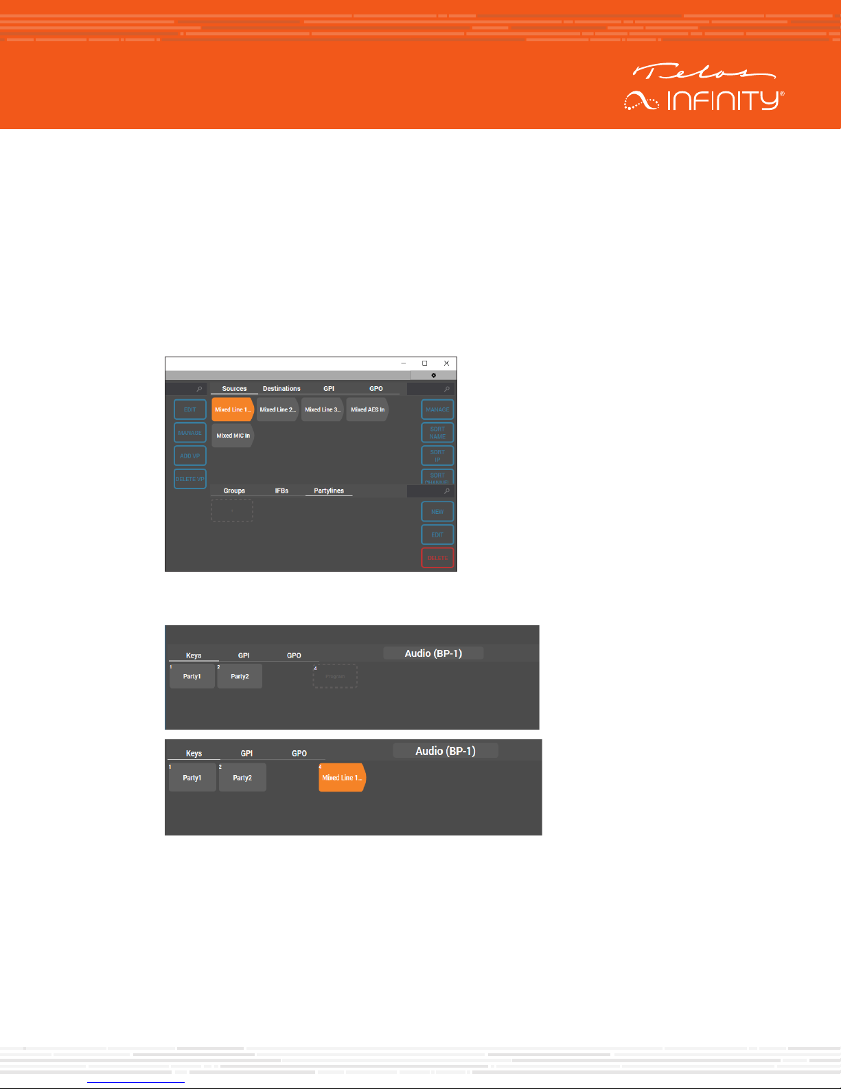
Adding a Program Source for monitoring
Dashboard running on a Windows PC will also be required to do this, along with a method to get the
audio on to the AoIP network, such as an Analog xNode offered by the Telos Alliance.
1. Open Dashboard
2. Let Dashboard scan the network (this can take up to 30 seconds)
3. Find the source you wish to use for the program input source (in this example, it will be
“Mixed Line 1”)
4. Drag and drop the program input source on to the “Program” button for each beltpack that
should have the program source available to them.
Page 10
USE CASES
Floor Manager 1 Stage Crew 1 Stage Crew 2 Lighting Desk
Sound Desk
Axia xSwitch Ethercon Breakout Panel
Lighting Operator
Sound Operator
Spotlight Op 1
Spotlight Op 2
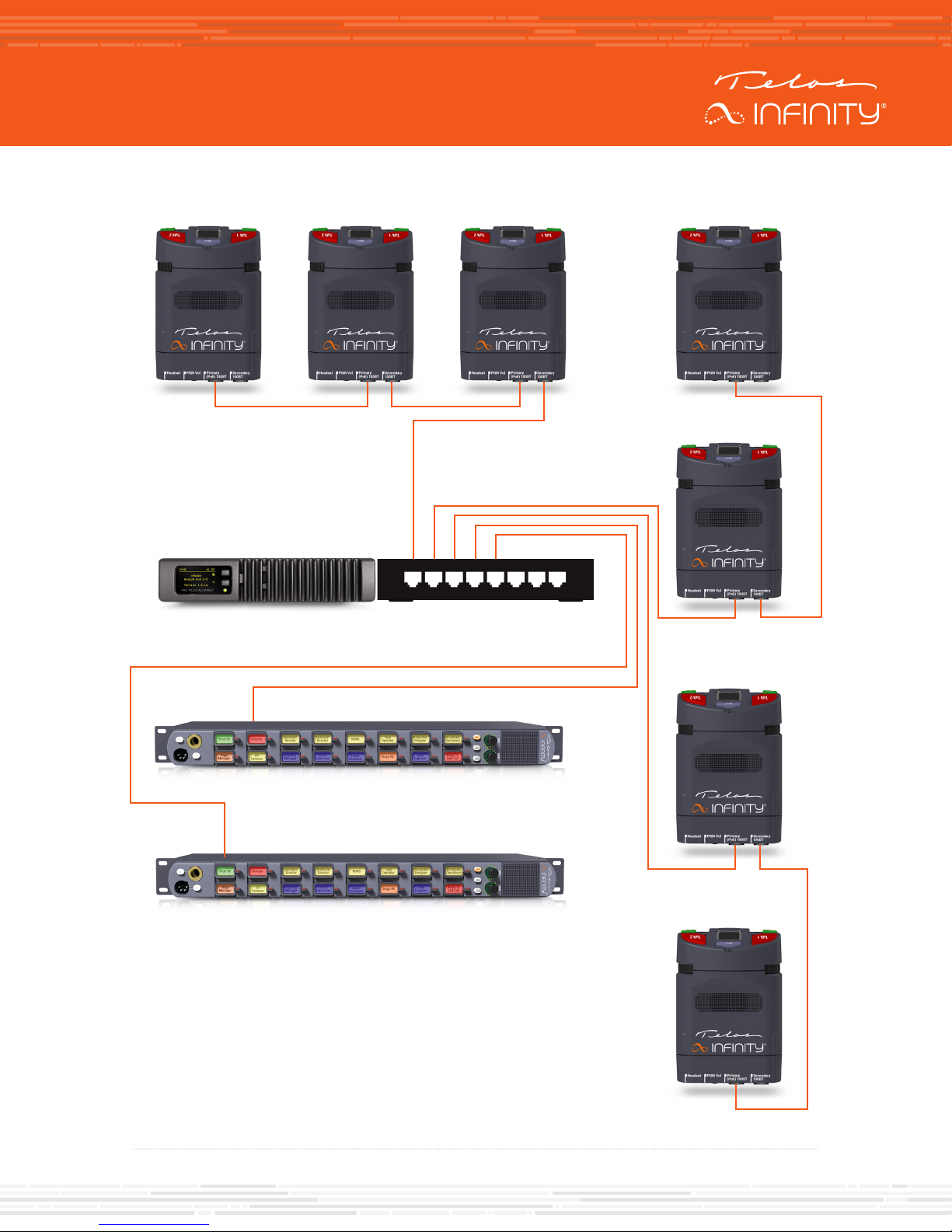
Figure 3 - Live Event Partyline System Example
Page 11
MENU STRUCTURE
Confirm
Cancel
Enter Menu
Call
Listen
Ch 1 Assign
Ch 2 Assign
Exit
Call
Listen
Ch 1 Assign
Ch 2 Assign
Contacts
Contacts List
Groups List
Exit
Partyline List
Exit
Groups
Partyline
Exit
Exit
Directory
User
Confirm
Cancel
Last Call
Log
Clear History
Exit
History
Confirm
Cancel
Kill Ch 2 Mics
Kill Ch 1 Mics
MENU STRUCTURE
Page 12
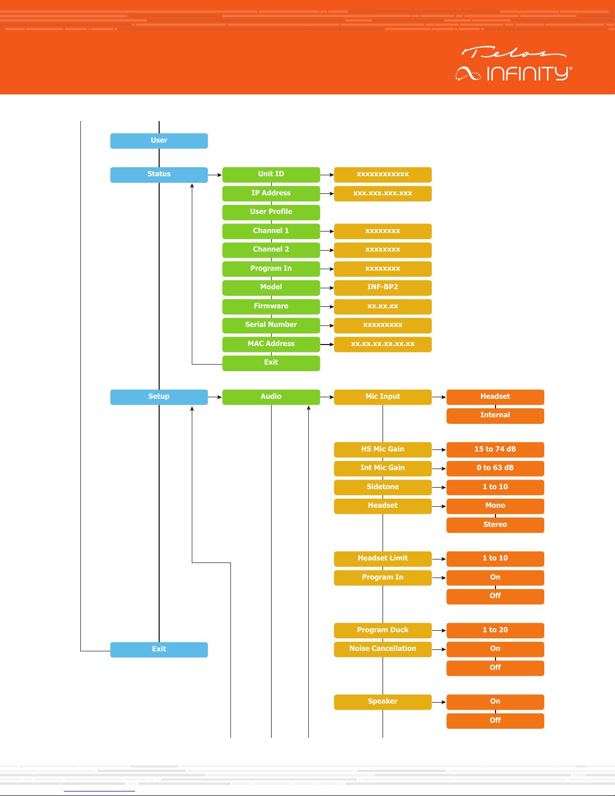
Confirm
Cancel
Call
Listen
Ch 1 Assign
Ch 2 Assign
Exit
Call
Listen
Ch 1 Assign
Ch 2 Assign
Contacts
Contacts List
Groups List
Exit
Partyline List
Exit
Groups
Partyline
Exit
Exit
Directory
User
Unit ID
IP Address
User Profile
Channel 1
Channel 2
Program In
Model
Firmware
Serial Number
MAC Address
Exit
xxxxxxxxxxxx
xxx.xxx.xxx.xxx
xxxxxxxx
xxxxxxxx
xxxxxxxx
INF-BP2
xx.xx.xx
xxxxxxxxx
xx.xx.xx.xx.xx.xx
Status
Audio
Mic Input
HS Mic Gain
Int Mic Gain
Sidetone
Headset
Headset Limit
Program In
Program Duck
Speaker
Headset
Internal
0 to 63 dB
15 to 74 dB
1 to 10
Mono
Stereo
1 to 10
On
Off
1 to 20
On
Off
On
Off
Setup
Exit
Confirm
Cancel
Last Call
Log
Clear History
Exit
History
Confirm
Cancel
Kill Ch 2 Mics
Kill Ch 1 Mics
Noise Cancellation
MENU STRUCTURE
Page 13
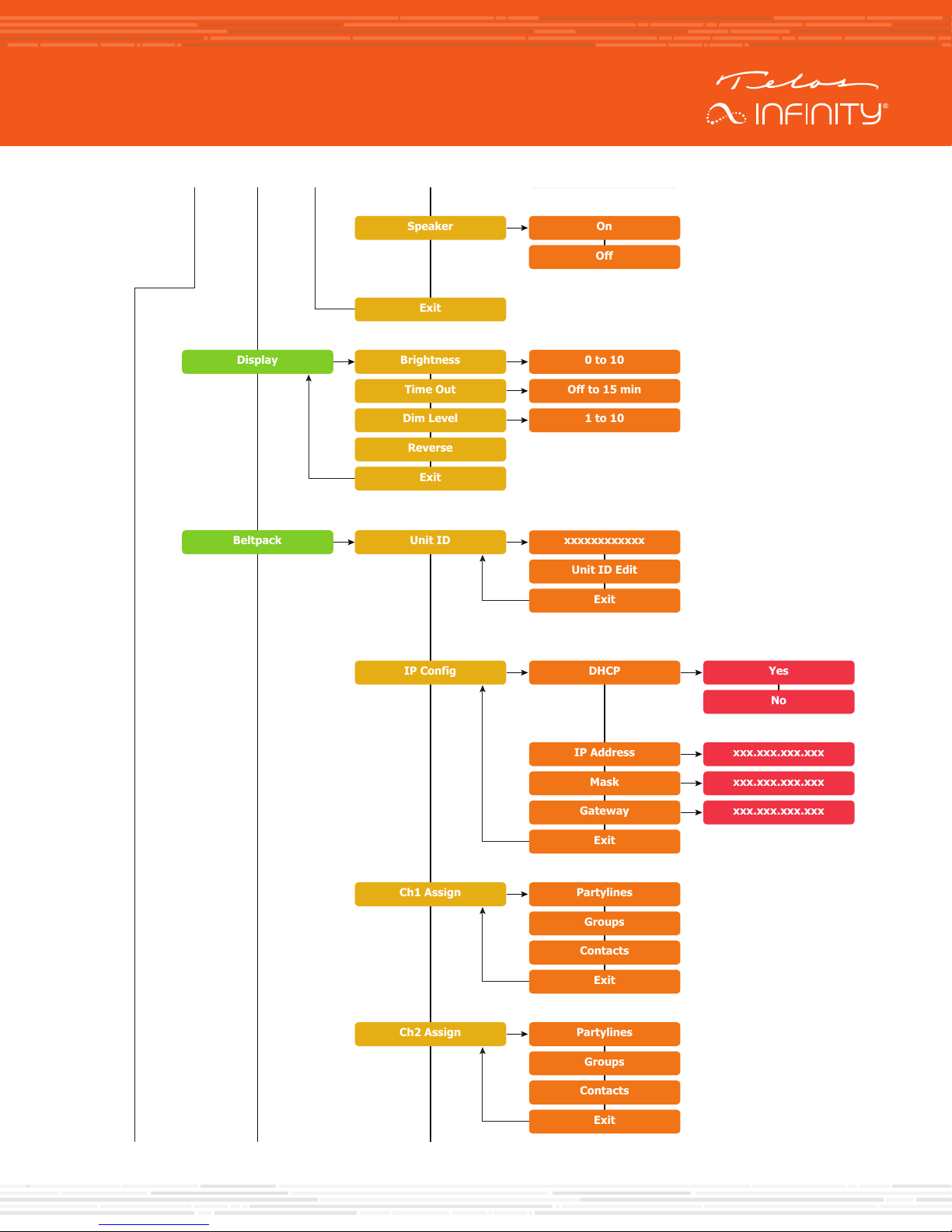
Confirm
Cancel
Call
Listen
Ch 1 Assign
Ch 2 Assign
Exit
Call
Listen
Ch 1 Assign
Ch 2 Assign
Contacts
Contacts List
Groups List
Exit
Partyline List
Exit
Groups
Partyline
Exit
Exit
Unit ID
IP Address
User Profile
Channel 1
Channel 2
Program In
Model
Firmware
Serial Number
MAC Address
Exit
xxxxxxxxxxxx
xxx.xxx.xxx.xxx
xxxxxxxx
xxxxxxxx
xxxxxxxx
INF-BP2
xx.xx.xx
xxxxxxxxx
xx.xx.xx.xx.xx.xx
Audio
Mic Input
HS Mic Gain
Int Mic Gain
Sidetone
Headset
Headset Limit
Program In
Program Duck
Speaker
Exit
Headset
Internal
0 to 63 dB
15 to 74 dB
1 to 10
Mono
Stereo
1 to 10
On
Off
1 to 20
On
Off
On
Off
Display
Brightness
Time Out
Dim Level
0 to 10
Off to 15 min
1 to 10
Reverse
Exit
xxxxxxxxxxxx
Unit ID Edit
Exit
Beltpack
Unit ID
DHCP
IP Address
Mask
Gateway
Exit
IP Config
Partylines
Groups
Contacts
Exit
Ch1 Assign
Partylines
Groups
Contacts
Exit
Ch2 Assign
Yes
No
xxx.xxx.xxx.xxx
xxx.xxx.xxx.xxx
xxx.xxx.xxx.xxx
Confirm
Cancel
Last Call
Log
Clear History
Exit
Confirm
Cancel
Noise Cancellation
MENU STRUCTURE
Page 14
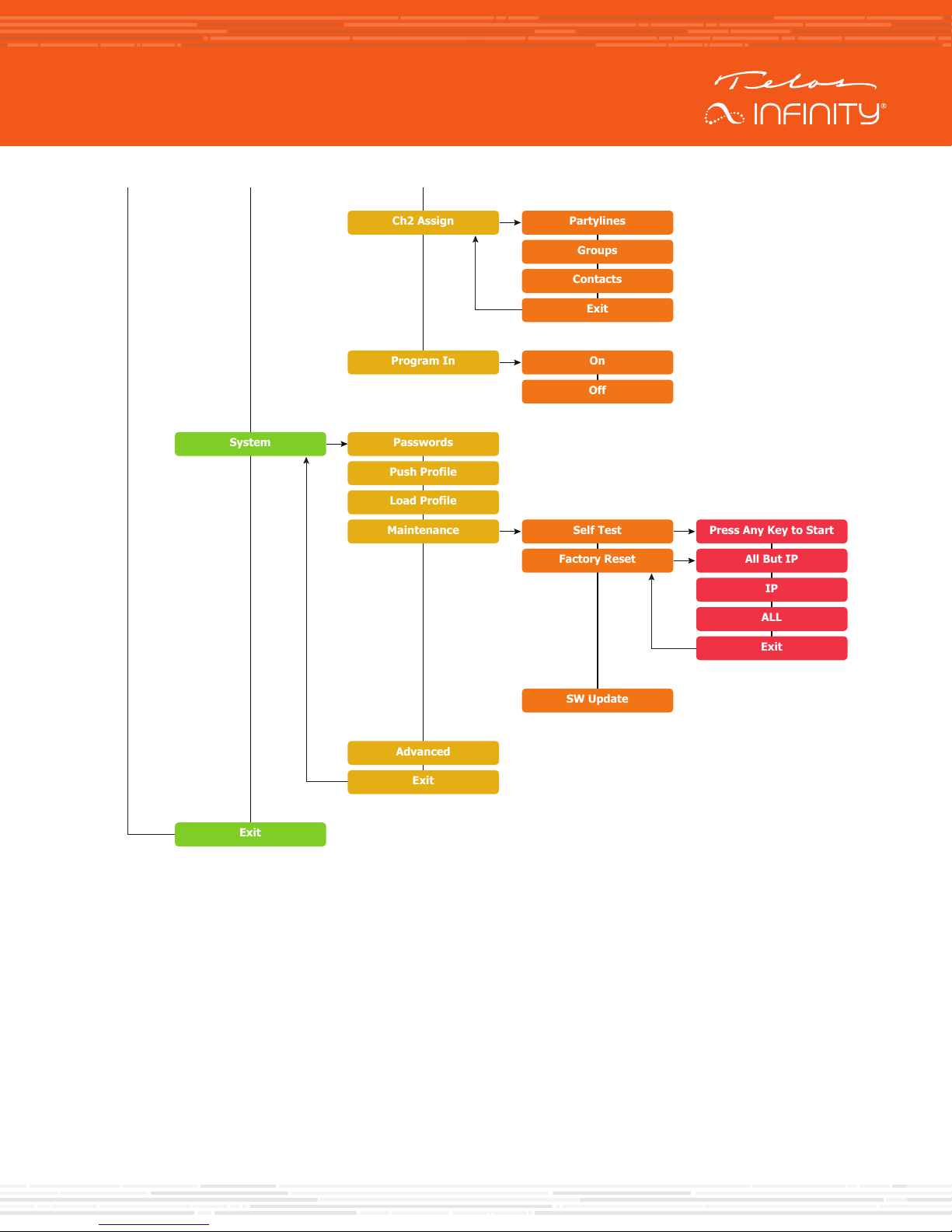
Confirm
Cancel
Call
Listen
Ch 1 Assign
Ch 2 Assign
Exit
Call
Listen
Ch 1 Assign
Ch 2 Assign
Contacts
Contacts List
Groups List
Exit
Partyline List
Exit
Groups
Partyline
Exit
Exit
Unit ID
IP Address
User Profile
Channel 1
Channel 2
Program In
Model
Firmware
Serial Number
MAC Address
Exit
xxxxxxxxxxxx
xxx.xxx.xxx.xxx
xxxxxxxx
xxxxxxxx
xxxxxxxx
INF-BP2
xx.xx.xx
xxxxxxxxx
xx.xx.xx.xx.xx.xx
Audio
Mic Input
HS Mic Gain
Int Mic Gain
Sidetone
Headset
Headset Limit
Program In
Program Duck
Speaker
Exit
Headset
Internal
0 to 63 dB
15 to 74 dB
1 to 10
Mono
Stereo
1 to 10
On
Off
1 to 20
On
Off
On
Off
Display
Brightness
Time Out
Dim Level
0 to 10
Off to 15 min
1 to 10
Reverse
Exit
xxxxxxxxxxxx
Unit ID Edit
Exit
Beltpack
Unit ID
DHCP
IP Address
Mask
Gateway
Exit
IP Config
Partylines
Groups
Contacts
Exit
Ch1 Assign
Partylines
Groups
Contacts
Exit
Ch2 Assign
On
Off
Self Test
Press Any Key to Start
All But IP
Yes
No
xxx.xxx.xxx.xxx
xxx.xxx.xxx.xxx
xxx.xxx.xxx.xxx
IP
ALL
Exit
Factory Reset
SW Update
Program In
System
Exit
Passwords
Push Profile
Load Profile
Maintenance
Advanced
Exit
Confirm
Cancel
Last Call
Log
Clear History
Exit
Confirm
Cancel
Noise Cancellation
MENU STRUCTURE
Page 15

QUICK-START INSTALLATION GUIDE
This Page Intentionally Left Blank
Page 16

QUICK-START INSTALLATION GUIDE
QUICK LINKS
Subscribe to DirectCurrent
Weekly updates on all things broadcast via email
TelosAlliance.com/directcurrent
Social Media
Facebook: /TelosAlliance
Twitter: @TelosAlliance
LinkedIn: /TelosAlliance
YouTube: TelosAllianceTV
Google+: +TelosAlliance
Product Catalog
TelosAlliance.com/now
24/7 Tech Support
Radio: +1 (216) 622-0247
TV: +1 (717) 735-3611
Radio: [email protected]
1241 Superior Ave. • Cleveland, Ohio, 44114, USA • +1.216.241.7225 • TelosAlliance.com
© 2019 TLS Corp. The Telos Alliance®. All Rights Reserved. C19/1/17034 1490-00188-002 --- QUICK START GUIDE: BELTPACK
 Loading...