

Page 1
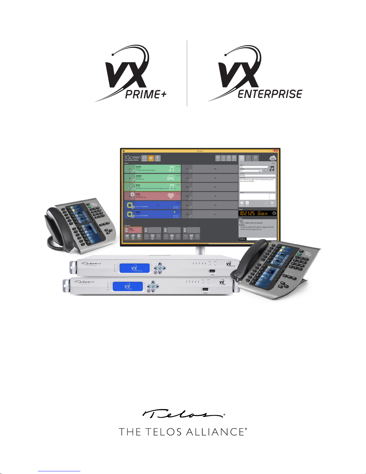
The Whole-Plant Broadcast Talkshow System
USER’S MANUAL
Version 1.4 | April 2019
TelosAlliance.com
Page 2

ii | TELOS VX ENTERPRISE / PRIME+ MANUAL
User Warnings and Cautions
The installation and service instructions in this manual are for use by qualified personnel only. To avoid
electric shock, do not perform any servicing other than that contained in the operating instructions
unless you are qualified to do so. Refer all servicing to qualified personnel
This instrument has an autoranging line voltage input. Ensure the power voltage is within the specified
range of 100-240VAC. The ~ symbol, if used, indicates an alternating current supply.
This symbol, wherever it appears, alerts you to the presence of uninsulated, dangerous voltage
inside the enclosure – voltage which may be sufficient to constitute a risk of shock.
This symbol, wherever it appears, alerts you to important operating and maintenance instructions. Read the manual.
CAUTION: HAZARDOUS VOLTAGES
The instrument power supply incorporates an internal fuse. Hazardous voltages may still be present on
some of the primary parts even when the fuse has blown. If fuse replacement is required, replace fuse
only with same type and value for continued protection against fire.
WARNING:
The product’s power cord is the primary disconnect device. The socket outlet should be located near
the device and easily accessible. The unit should not be located such that access to the power cord is
impaired. If the unit is incorporated into an equipment rack, an easily accessible safety disconnect
device should be included in the rack design.
To reduce the risk of electrical shock, do not expose this product to rain or moisture. This unit is for
indoor use only.
This equipment requires the free flow of air for adequate cooling. Do not block the ventilation openings
on the rear and sides of the unit. Failure to allow proper ventilation could damage the unit or create a
fire hazard. Do not place the units on a carpet, bedding, or other materials that could interfere with any
panel ventilation openings.
If the equipment is used in a manner not specified by the manufacturer, the protection provided by the
equipment may be impaired.
USA CLASS A COMPUTING DEVICE INFORMATION TO USER.
WARNING:
This equipment generates, uses, and can radiate radio-frequency energy. If it is not installed and used as
directed by this manual, it may cause interference to radio communication. This equipment complies
with the limits for a Class A computing device, as specified by FCC rules, part 15, subpart j, which are
designed to provide reasonable protection against such interference when this type of equipment is operated in a commercial environment. Operation of this equipment in a residential area is likely to cause
interference. If it does, the user will be required to eliminate the interference at the user’s expense.
Note: objectionable interference to TV or radio reception can occur if other devices are connected to
this device without the use of shielded interconnect cables. FCC rules require the use of shielded cables.
Page 3

TELOS VX ENTERPRISE/PRIME+ MANUAL | III
CANADA WARNING:
“This digital apparatus does not exceed the Class A limits for radio noise emissions set out in the radio
interference regulations of the Canadian department of communications.”
“Le présent appareil numérique n’émet pas de bruits radioélectriques dépassant les limites applicables
aux appareils numériques (de Class A) prescrites dans le règlement sur le brouillage radioélectrique
édicté par le ministère des communications du Canada.”
CE CONFORMANCE INFORMATION:
This device complies with the requirements of the EEC council directives:
♦ 93/68/EEC (CE MARKING)
♦ 73/23/EEC (SAFETY – LOW VOLTAGE DIRECTIVE)
♦ 89/336/EEC (ELECTROMAGNETIC COMPATIBILITY)
Conformity is declared to those standards: EN50081-1, EN50082-1.
Trademarks, Patents, and Licenses
Telos is a trademark of TLS Corp. All other trademarks are the property of their respective holders.
All versions, claims of compatibility, trademarks, etc. of hardware and software products not made by
The Telos Alliance which are mentioned in this manual or accompanying material are informational
only. The Telos Alliance makes no endorsement of any particular product for any purpose, nor claims
any responsibility for operation or accuracy. We reserve the right to make improvements or changes
in the products described in this manual which may affect the product specifications, or to revise the
manual without notice.
This document and its content are copyrighted by TLS Corporation and may not be copied, reproduced,
or distributed in any form without expressed written permission.
Patent information can be found at www.TelosAlliance.com/legal
Updates
Telos VX Prime+, and VX Enterprise features and operations are determined largely by software. The
Telos Alliance strives to provide the most stable and feature-rich software available. We encourage you
to check for software updates from time to time by visiting our website or by contacting us directly.
Feedback
We welcome feedback on any aspect of our products or this manual. In the past, many good ideas from
users have made their way into software revisions or new products. Please contact us with your comments or suggestions.
Page 4

iv | TELOS VX ENTERPRISE / PRIME+ MANUAL
We support you…
By Phone/Fax
You may reach our Telos Support Team in emergencies by calling +1 216-622-0247. For billing questions
or other non-emergency technical questions, call +1 216-241-7225 between 9:00 AM to 5:00 PM USA
Eastern Time, Monday through Friday.
By Email.
Non-emergency technical support is available at [email protected].
By Web
The Telos Web site has a variety of information that may be useful for product selection and support. The
URL is https://www.telosalliance.com/Telos .
SERVICE
You must contact Telos Alliance before returning any equipment for factory service. We will need your
unit’s serial number, located on the back of the unit. We will issue a return authorization number, which
must be written on the exterior of your shipping container. Please do not include cables or accessories unless specifically requested by the Technical Support Engineer. Be sure to adequately insure your shipment
for its replacement value. Packages without proper authorization may be refused. US customers, please
contact Telos Alliance Technical Support at +1-216-622-0247. All other customers should contact local
representative to make arrangements for service.
Warranty
For the latest Telos Alliance warranty, visit: telosalliance.com/warranty
Register your product
Register your product today to get the full benefits of our warranty, support, and product updates.
telosalliance.com/product-registration/
The Telos Alliance
1241 Superior Ave. Cleveland, OH 44114 USA
+1 (216) 241-7225
For Telos Support:
Page 5

TABLE OF CONTENTS | V
Table of Contents
User Warnings and Cautions . . . . . . . . . . . . . . . . . . . . . . . . . ii
We support you… . . . . . . . . . . . . . . . . . . . . . . . . . . . . . iv
Warranty . . . . . . . . . . . . . . . . . . . . . . . . . . . . . . . . . . iv
Creating the Most Exciting Audio Experiences . . . . . . . . . . . . . . . . . ix
1 About this Manual 1
1 Welcome 2
The VX Enterprise and VX Prime+ Engines . . . . . . . . . . . . . . . . . . . 3
Overview . . . . . . . . . . . . . . . . . . . . . . . . . . . . . . 3
Features . . . . . . . . . . . . . . . . . . . . . . . . . . . . . . . 3
The VSet Phone Controllers . . . . . . . . . . . . . . . . . . . . . . . . . . 4
VSet Desktop Controller . . . . . . . . . . . . . . . . . . . . . . . . . . . 5
Fusion and iQ Console Controllers . . . . . . . . . . . . . . . . . . . . . . . 5
VSet Console Controller . . . . . . . . . . . . . . . . . . . . . . . . . . . 6
VX call screening software applications . . . . . . . . . . . . . . . . . . . . 6
The Livewire+ AOIP Network. . . . . . . . . . . . . . . . . . . . . . . . . 7
The Acoustic Echo Canceller . . . . . . . . . . . . . . . . . . . . . . . . . 7
2 Installation and Conguration 8
Connecting to the PSTN: PBXs and Providers . . . . . . . . . . . . . . . . . . 8
What’s today’s equivalent of a ‘Line’? . . . . . . . . . . . . . . . . . . . . . 9
Livewire+ is used for audio I/O . . . . . . . . . . . . . . . . . . . . . . . . 14
Step-By-Step Summary . . . . . . . . . . . . . . . . . . . . . . . . . . . 15
Racking Instructions. . . . . . . . . . . . . . . . . . . . . . . . . . . . . 15
Rear Panel Connections . . . . . . . . . . . . . . . . . . . . . . . . . . . 18
Getting the VX on the Network(s). . . . . . . . . . . . . . . . . . . . . . . 18
VSet Installation . . . . . . . . . . . . . . . . . . . . . . . . . . . . . .21
System Conguration . . . . . . . . . . . . . . . . . . . . . . . . . . . . 21
Selectable and Fixed Lines Dened . . . . . . . . . . . . . . . . . . . 21
Studios and Shows Dened . . . . . . . . . . . . . . . . . . . . . .22
Conguration Web Pages . . . . . . . . . . . . . . . . . . . . . . . . . .22
Main Conguration Page . . . . . . . . . . . . . . . . . . . . . . .23
SIP Conguration Page . . . . . . . . . . . . . . . . . . . . . . . . . . .25
SIP Server Conguration . . . . . . . . . . . . . . . . . . . . . . . . . . . 26
Page 6

vi | TABLE OF CONTENTS
Studios Menu . . . . . . . . . . . . . . . . . . . . . . . . . . . . . . . . 29
Show Conguration . . . . . . . . . . . . . . . . . . . . . . . . . . . . . 33
Individual Show Conguration Pages . . . . . . . . . . . . . . . . . . . . . 33
Call Audio Processing Page . . . . . . . . . . . . . . . . . . . . . . . . . . 34
Assigning Sounds & Tones – The Tones page . . . . . . . . . . . . . . . . . . 35
Information Pages . . . . . . . . . . . . . . . . . . . . . . . . . . . . .37
SIP and Network Address Translation (NAT) . . . . . . . . . . . . . . . 28
Regarding Codecs and SIP . . . . . . . . . . . . . . . . . . . . . . . 28
Individual Studio Conguration Pages . . . . . . . . . . . . . . . . .29
On Air DTMF Conguration. . . . . . . . . . . . . . . . . . . . . . . 36
Ringtone Conguration . . . . . . . . . . . . . . . . . . . . . . . . 36
SIP and DTMF . . . . . . . . . . . . . . . . . . . . . . . . . . . .37
Studios Information Menu and Pages . . . . . . . . . . . . . . . . . . 37
Calls Information Page . . . . . . . . . . . . . . . . . . . . . . . .38
Devices Information Page . . . . . . . . . . . . . . . . . . . . . . . 38
Stream Statistics Information Page . . . . . . . . . . . . . . . . . . . 38
System Status Page . . . . . . . . . . . . . . . . . . . . . . . . . . . . . 38
Licenses Page . . . . . . . . . . . . . . . . . . . . . . . . . . . . . . . . 38
System Logs Page . . . . . . . . . . . . . . . . . . . . . . . . . . . . . . 39
Firmware Update Page . . . . . . . . . . . . . . . . . . . . . . . . . . .39
Backing up and Restoring Engine Conguration . . . . . . . . . . . . . . . .40
3 Operation 41
VSet Operation . . . . . . . . . . . . . . . . . . . . . . . . . . . . . . . 41
Select Studio and Show . . . . . . . . . . . . . . . . . . . . . . . . 41
Set Talent or Producer Mode . . . . . . . . . . . . . . . . . . . . . . 41
The Line Info Display . . . . . . . . . . . . . . . . . . . . . . . . .41
Next indicator . . . . . . . . . . . . . . . . . . . . . . . . . . . .41
Fader number . . . . . . . . . . . . . . . . . . . . . . . . . . . .41
Line name . . . . . . . . . . . . . . . . . . . . . . . . . . . . . . 42
Caller ID . . . . . . . . . . . . . . . . . . . . . . . . . . . . . . . 42
Time . . . . . . . . . . . . . . . . . . . . . . . . . . . . . . . .42
Action Prompt . . . . . . . . . . . . . . . . . . . . . . . . . . . . 42
Line Status Icons . . . . . . . . . . . . . . . . . . . . . . . . . . . 42
Page 7

TABLE OF CONTENTS | VII
Line Button Columns . . . . . . . . . . . . . . . . . . . . . . . . . 43
Hold Button . . . . . . . . . . . . . . . . . . . . . . . . . . . . . 44
Drop button . . . . . . . . . . . . . . . . . . . . . . . . . . . . . 44
Lock . . . . . . . . . . . . . . . . . . . . . . . . . . . . . . . . . 44
Next Button and Function . . . . . . . . . . . . . . . . . . . . . . . 45
Block All . . . . . . . . . . . . . . . . . . . . . . . . . . . . . . . 45
Numeric Keypad and GO Button . . . . . . . . . . . . . . . . . . . .45
Re-dial Function . . . . . . . . . . . . . . . . . . . . . . . . . . . 45
Fader Assign . . . . . . . . . . . . . . . . . . . . . . . . . . . . . 45
Firmware Upgrades . . . . . . . . . . . . . . . . . . . . . . . . . . 46
Take it Easy . . . . . . . . . . . . . . . . . . . . . . . . . . . . . . 46
Some Common Questions . . . . . . . . . . . . . . . . . . . . . . . 46
4 Appendix 47
Basic Studio Setup with xNode I/O . . . . . . . . . . . . . . . . . . . . . .47
Physical GPIO Reference . . . . . . . . . . . . . . . . . . . . . . . . . . . 49
GPIO Port Wiring . . . . . . . . . . . . . . . . . . . . . . . . . . . 50
Setting up a Mute Ringer GPI . . . . . . . . . . . . . . . . . . . . .50
Setting up a Ringing Indication GPO . . . . . . . . . . . . . . . . . .51
Single Mix Minus Routing with xNode. . . . . . . . . . . . . . . . . . . . . 52
Operation with Fusion Consoles . . . . . . . . . . . . . . . . . . . . . . . . 56
Setting it up . . . . . . . . . . . . . . . . . . . . . . . . . . . . . 57
Ringer Mute . . . . . . . . . . . . . . . . . . . . . . . . . . . . . 58
Operation with QOR and iQx Consoles . . . . . . . . . . . . . . . . . . . . . 58
Setting it up . . . . . . . . . . . . . . . . . . . . . . . . . . . . . 58
Ringer Mute . . . . . . . . . . . . . . . . . . . . . . . . . . . . . 59
Setting up and Using “Dummy” Studios . . . . . . . . . . . . . . . . . . . . 59
Creating an Asterisk Extension for VX . . . . . . . . . . . . . . . . . . . . . 62
Before we begin . . . . . . . . . . . . . . . . . . . . . . . . . . .62
Creating a Generic SIP Extension . . . . . . . . . . . . . . . . . . . . 62
Extension Options . . . . . . . . . . . . . . . . . . . . . . . . . .63
DID’s. . . . . . . . . . . . . . . . . . . . . . . . . . . . . . . . . 64
Conguring VX to talk to Asterisk . . . . . . . . . . . . . . . . . . . . 65
Asterisk – Rebooting and Accessing . . . . . . . . . . . . . . . . . . . . . . 66
Changing Power Supplies . . . . . . . . . . . . . . . . . . . . . . . . . .66
Page 8

Resources and Tools . . . . . . . . . . . . . . . . . . . . . . . . . . . . . 68
Internet Speed tests . . . . . . . . . . . . . . . . . . . . . . . . . . 68
Internet VOIP Jitter Test . . . . . . . . . . . . . . . . . . . . . . . . 68
Packet “snier” . . . . . . . . . . . . . . . . . . . . . . . . . . . . 68
VoIP Soft phone” SIP PC clients . . . . . . . . . . . . . . . . . . . . . 68
Open Source PBX Distributions . . . . . . . . . . . . . . . . . . . . . 68
Commercial PBX Products . . . . . . . . . . . . . . . . . . . . . . . 68
VoIP/SIP equipment suppliers . . . . . . . . . . . . . . . . . . . . . 69
Telephony Discussion and VoIP news sites . . . . . . . . . . . . . . . . 69
SIP Information and suggested reading . . . . . . . . . . . . . . . . . 70
Books . . . . . . . . . . . . . . . . . . . . . . . . . . . . . . . . 70
Specications . . . . . . . . . . . . . . . . . . . . . . . . . . . . . . . . 71
General . . . . . . . . . . . . . . . . . . . . . . . . . . . . . . . 71
Analog Inputs (with Telos Alliance xNode) . . . . . . . . . . . . . . . . 71
Analog Outputs (with Telos Alliance xNode) . . . . . . . . . . . . . . . 71
Digital Audio Inputs and Outputs . . . . . . . . . . . . . . . . . . . . 71
Frequency Response . . . . . . . . . . . . . . . . . . . . . . . . .72
Dynamic Range . . . . . . . . . . . . . . . . . . . . . . . . . . . . 72
Total Harmonic Distortion + Noise . . . . . . . . . . . . . . . . . . . 72
IP/Ethernet Connections . . . . . . . . . . . . . . . . . . . . . . . . 72
Processing Functions . . . . . . . . . . . . . . . . . . . . . . . . . 72
Power Supply AC Input . . . . . . . . . . . . . . . . . . . . . . . .73
Operating Temperatures . . . . . . . . . . . . . . . . . . . . . . . . 73
Studio Audio Connections . . . . . . . . . . . . . . . . . . . . . . . 73
Telco Connections. . . . . . . . . . . . . . . . . . . . . . . . . . . 73
Regulatory . . . . . . . . . . . . . . . . . . . . . . . . . . . . . . 73
Telos VX Tech Quick Reference Pages . . . . . . . . . . . . . . . . . . . . .74
Default Passwords: . . . . . . . . . . . . . . . . . . . . . . . . . . 74
Default IP Addresses: . . . . . . . . . . . . . . . . . . . . . . . . . 74
SIP Parameters . . . . . . . . . . . . . . . . . . . . . . . . . . . . 74
TCP/IP Ports and protocols used by the VX System . . . . . . . . . . . .74
VSet Phone Set . . . . . . . . . . . . . . . . . . . . . . . . . . . . 75
C Telos Alliance Warranty 76
Page 9

Creating the Most Exciting and Engaging
Audio Experiences Imaginable
Congratulations on your new Telos Alliance product!
The gang here at Telos is committed to shaping the future of audio by delivering innovative, intuitive
solutions that inspire our customers to create the most exciting and engaging audio experiences imaginable.
We’re grateful that you have chosen audio tools from Telos® Systems, Omnia® Audio, Axia® Audio,
Linear Acoustic®, 25-Seven Systems®, and Minnetonka Audio®. We’re here to help you make your
work truly shine. We hope that you enjoy your Telos Alliance product for many years to come and won’t
hesitate to let us know if we can help in any way.
The Telos Alliance
Page 10

About this Manual
1
This little book we call “The Read Guy”. It means that we think that what he’s pointing at is important
but might be easily missed. This is very similar to what was done in the old Bell System Practices
books. We hope that you nd this helpful and even a bit amusing. Show it to an “old phone guy” if
you can.
The best VX installations are well planned in advance of their deployment and most successful when the plan is well executed.
The VX is very different than most broadcast phone hybrids. You’ll be well served to spend a little time with this book and on
the phone with an Applications Engineer from Telos who’s installed hundreds of VX systems. Both will be well worth your
while.
Thanks for considering and purchasing the Telos VX, conceived by a great Broadcast Engineer and our founder Steve Church.
Our developers and support team have spent a lot of time learning and developing “Best Practices” for its use and we are proud
of the product and the facilities that host it. The best broadcast facilities in the world have adopted the VX to satisfy their
broadcast telephone requirements. We intend to earn your trust and enthusiastic support every day.
This manual covers the VX Enterprise and VX Prime+ systems.
- The VX and VX Prime use the 2u “Fanless engine” hardware platform.
- The VX Enterprise and VX Prime+ use the new 1u server platform to support AES-67 capabilities and improvements.
Page 11

WELCOME
CHAPTER 1
| 2
1 Welcome
The VX is a telephone system designed for studio use by broadcasters. It’s different from your office phones because broadcast
talent and producers have different needs than most other typical telephone users. We designed it to do exactly what you need
in the studio. It has bright clear displays, tougher, bigger buttons and extra functionality that isn’t found in a common office
phone.
The VX system is typically composed of these parts: the engine, Vset phones, a variety of optional call controllers, xNode
audio interfaces (for non-axia plants) and a Livewire/AES67 capable switch, set up to handle the Livewire audio and control
protocols.
The VX, configured appropriately, supports many studios and what we call “Shows.” In in VX, “Studios” are a collection of I/O
configuration (audio and control) that are generally associated with a particular studio. The caller audio channels, the Mix
Minus send to call channels, GPIO for flashing lights and the delay dump button. There is also the “Show”, that is, what lines
appear on the users phones when that show is selected. A typical show would have say 6 call in lines in hunting, a couple of
“warm” or VIP lines and a hot line.
The VX supports 24 “phone faders” (telephone “hybrids”). These may be divided among studios. The limitation is mainly due
to CPU resources. There may be situations that allow more hybrids. It’s best to arrange for a call with a Telos Field Applications
Engineer if you get “close” to the maximum number of 24 or have a very large number of Vsets.
The Engine pretends to be a bunch of SIP telephones (called “endpoints” by the IT crowd) on a PBX or from a Provider. It looks
and feels like the familiar “Key System” of days gone (mercifully) by, but produces the best sounding phone audio that you’ve
ever heard. The workflow was designed for broadcast use specifically, making it easy to move studios (and take your phone
numbers with you).
Since this is the next generation of VX Engines, this is the second revision of the VX manual. The first was created back in
2012 and was co-written by Steve Church, Founder of Telos and myself. In that time, many hundreds of VX systems have been
installed around the world with great success, and we’ve learned a lot. Steve came up with the idea of the VX back when it
sounded like it was “way off in the future.” The future got here very quickly! At the time of this writing, December 2018, SIP is
now a standard offering by most telephone service providers in the world. Every PBX currently manufactured supports SIP in
some way. A notable exception to this is Microsoft’s offering. Once called “Lync” and currently known as “Skype for Business”,
it’s probably best to avoid it for broadcast use. Oddly SIP can be supported by it using special hardware gateways.
Reading the manual from the original VX System reminded me of how quickly the voice network and its operators have
changed, and also of the magnitude of the changes! In the manual for the original VX, Steve talked about the archaic POTS
signaling methods and the challenges of making a hybrid work on them. That all seems so distant and quaint today, but the
changes that have occurred in telephony have been so ubiquitous that discussing the olden days of telecom technology is barely
relevant anymore.
If you’re new to VoIP and SIP, we can help. We’ve done so many of these systems that I like to say “We’ve already made the
mistakes so that you don’t have to.” We’ll try to make things clear in the pages that follow. SIP has a lot in common with the
former ISDN standard. In common are digital four wire audio, and message-based call set up and signaling. These properties
essentially bring the central office into your studio and improve audio and overall reliability. A SIP trunk, on an IP PBX is very
similar to an ISDN PRI: It has multiple digital audio channels, supports Direct inward Dial (DID) numbers and caller ID. VoIP
expands the feature set beyond what ISDN was capable of, or even imagined by its designers.
Page 12
WELCOME
CHAPTER 1
| 3
The VX Enterprise and VX Prime+ Engines
Overview
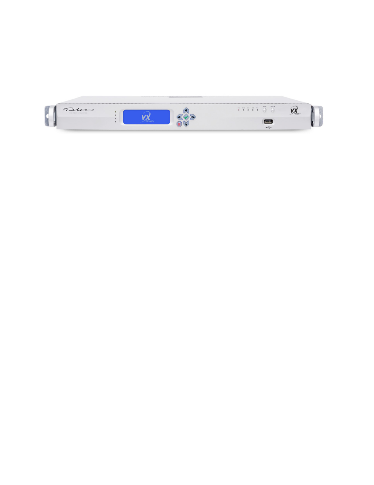
Telos VX® is the world’s first VoIP (Voice over IP) talkshow system — a broadcast phone system that’s so powerful, it can
run all the on-air phones for your entire plant. Telos VX Enterprise™, with built-in support for AES67, is the next evolution of
Telos VX VoIP phone system in a powerful new 1RU hardware unit. Additionally, support for the G.722 voice codec ensures
the highest quality calls from supported mobile devices. With capacity expandable to up to 120 hybrids/faders, VX Enterprise
is ideal for medium to large facilities and can grow with your station over time. For smaller facilities, the VX Prime+ with
8-hybrid capacity is available.
Call handling is sophisticated and flexible. Lines may be readily shared among studios. A web interface allows easy assignment
of lines to “Shows,” which can then be selected by users on the studio controllers. Each studio can provide its own Programon-Hold. Audio processing features also have taken a leap forward. Multiple calls can be conferenced and aired simultaneously
with excellent quality. Each line is equipped with AGC, automatic EQ processing, and override ducking. Caller audio is
incredibly consistent from call to call, in terms of both level and even in spectral content.
AES67 support brings a new level of compatibility and flexibility to VX phone systems. Support for AES67 gives broadcasters
the flexibility of integrating VX Enterprise into any AES67 environment, in addition to our own Axia® Livewire® network.
With plug-and-play connectivity, you can network multiple channels of audio with any manufacturer’s AES67-compliant
hardware. Beyond AES67, Livewire+ users have the added convenience and power of networking control (GPIO), advertising/
discovery, and program associated data throughout the network.
All connections to the Engine are via two Ethernet jacks that are extended with an Ethernet switch to support a wide variety
of peripherals: telephone lines, Livewire+ studio audio, VSet controllers, VX Producer PC applications, console-integrated
controllers, etc.
Features
♦ VX is the world’s first VoIP telephone system designed and built specifically for broadcasting.
♦ Includes support for AES67, giving broadcasters added flexibility of integrating VX Enterprise into any AES67 network,
in addition to our own Axia Livewire network.
♦ Standards-based SIP/IP interface integrates with most VoIP-based PBX systems to allow transfers, line-sharing, Caller ID
and common telco services for business and studio phones.
♦ Standard Ethernet backbone provides a common transport path for both studio audio and telecom needs, resulting in
cost savings and a simplified studio infrastructure. Connection of up to 100 control devices (software or hardware) is
possible.
♦ Modular, scalable system can be easily expanded and configured to manage a network of 60 or even more studios, each
with a dedicated Program-On-Hold input—truly a “whole-plant” solution for on-air phones.
♦ VX Prime+ supports up to 8 hybrids.
♦ VX Enterprise Base system is licensed for up to 24 hybrids and may be expanded in license increments of 8 up to a total of
120 hybrids.
Page 13
WELCOME
♦ Native Livewire integration: One connection integrates caller audio, program-on-hold, mix-minus, and logic directly
into Axia AoIP consoles and networks.
♦ Connect VX Enterprise to any radio console or other broadcast equipment using available Telos Alliance AES/EBU,
Mixed Signal, and GPIO xNodes. Audio interfaces feature 48 kHz sampling rate and studio-grade 24-bit A/D converters
with 256x oversampling.
♦ Powerful dynamic line management enables instant reallocation of call-in lines to studios requiring increased capacity.
♦ VSet Call Controllers™ with full-color LCD displays and Telos Status Symbols™ present producers and talent with a rich
graphical information display. Each VSet features its own address book and call log.
♦ Drop-in modules can integrate VX Enterprise or VX Prime+ phone control directly into your Axia mixing consoles.
♦ Clear, clean caller audio from 5th-generation Telos Adaptive Hybrid technology, including Digital Dynamic EQ, AGC,
adjustable caller ducking, and send- and receive-audio dynamics processing by Omnia®.
♦ Wideband acoustic echo cancellation from Fraunhofer completely eliminates open-speaker feedback.
♦ Support for G.722 codec enables high-fidelity phone calls from iPhone and Android SIP softphones using a SIP server.
CHAPTER 1
The VSet Phone Controllers
| 4
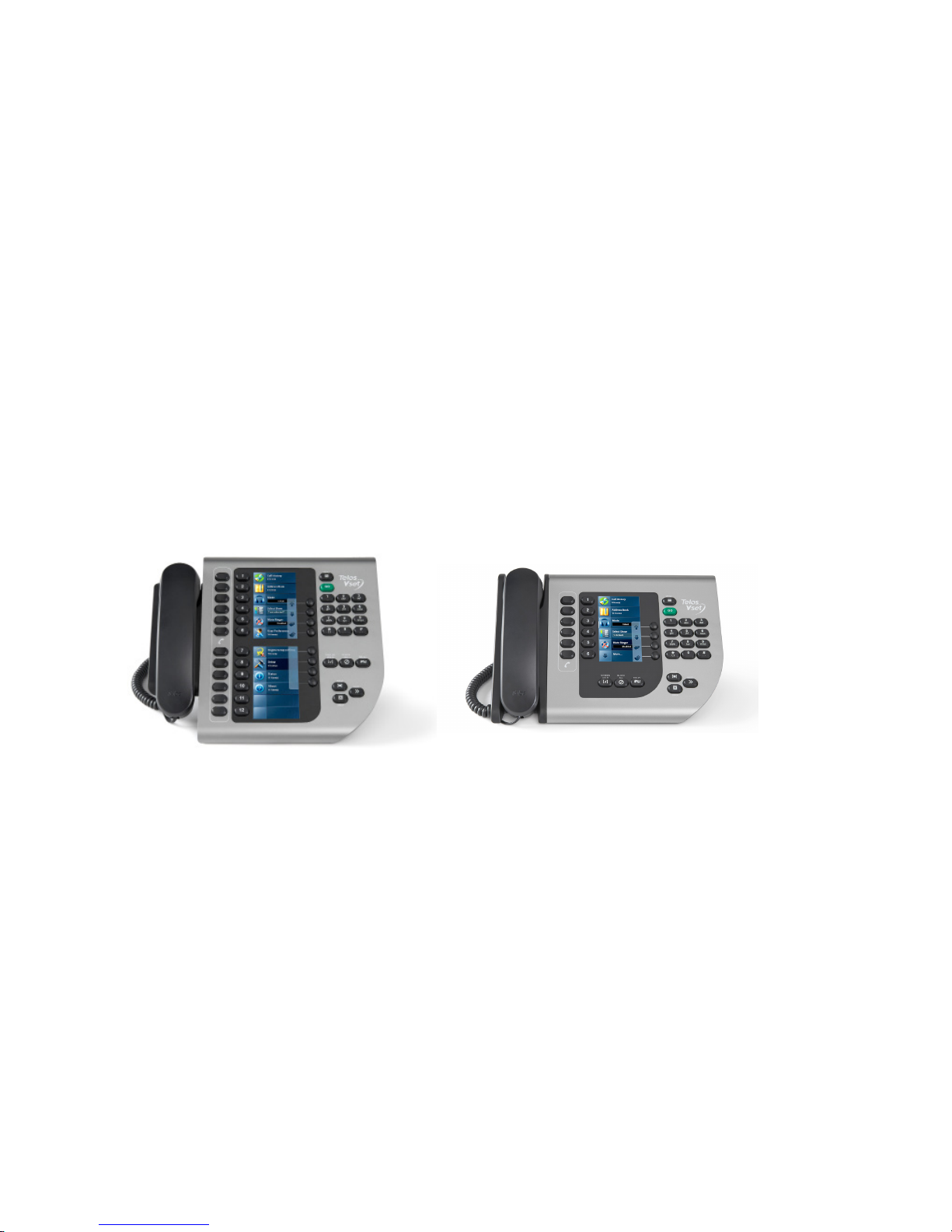
While you can control the VX with PC applications and mixing consoles, most systems will include one or more Telos VSets.
These are the phone-like controllers that have handsets for off-air conversations. These are available in 6 or 12 line models.
IP-based Telos VSet phones have large, high-contrast color LCD panels that provide line status, screening status, and caller
information. Caller description text that is entered into compatible call screening applications will show up on the LCD next to
the line select buttons.
For the comfort of familiarity, the VX can work like a traditional Telos controller, with calls being selected, held, and dropped
in the way to which operators have grown accustomed.
Page 14
WELCOME
VSet Desktop Controller
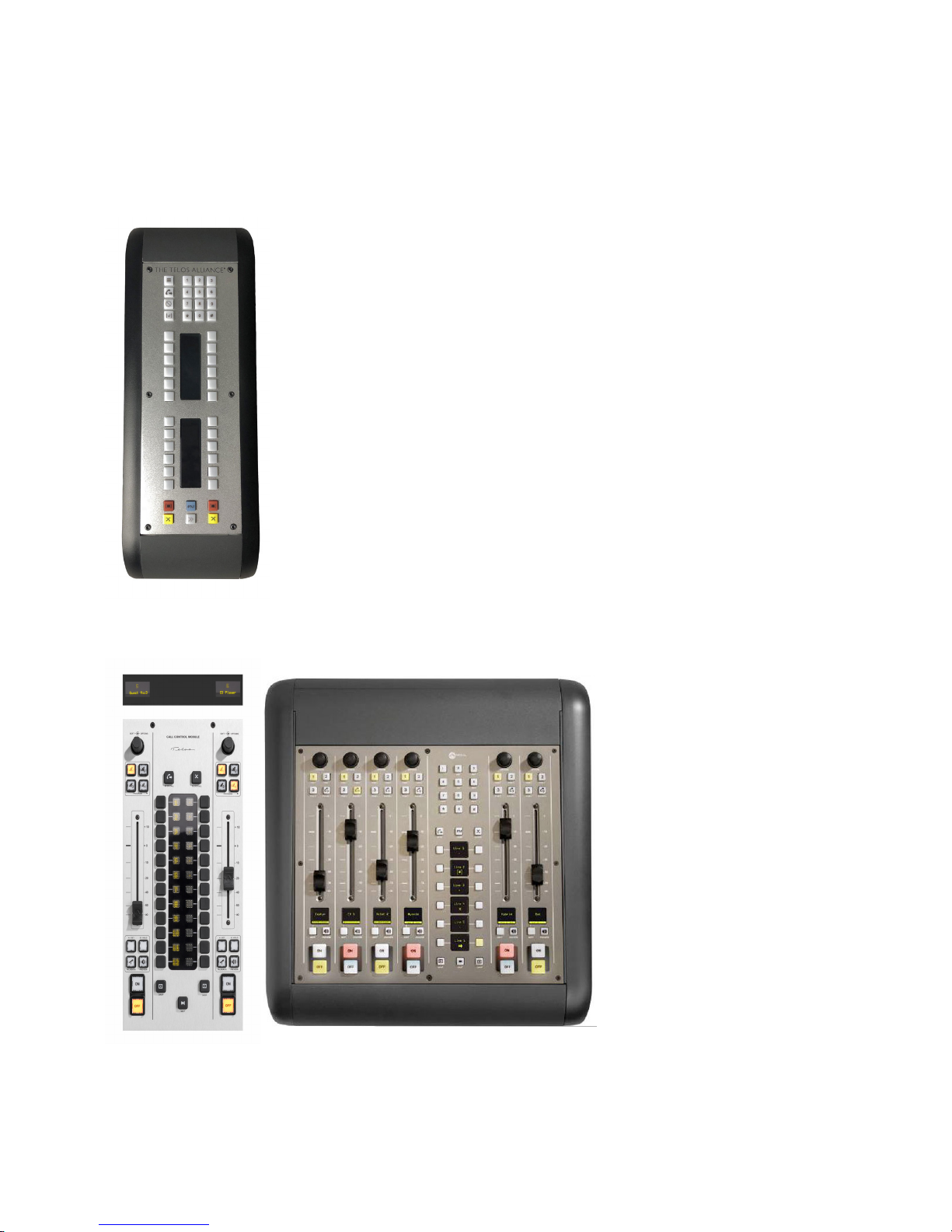
The Telos VSet Desktop Controller with visual line-status indicators provides selection and
control of up to 12 callers. Includes standard controls to allow fast, error-free talent operation,
including Take, Drop, Hold, and Busy keys. Telos exclusive “Next Call” key speeds workflow
for producers, and talent; built-in keypad allows on-hybrid dialing of outgoing numbers. VSet
Desktop Controller works in talent mode only.
CHAPTER 1
| 5
Fusion and iQ Console Controllers
The Fusion Controller Module and iQ 6-Fader Expansion provides the ideal way to integrate broadcast phones into the on-air
console—the control center of every studio. VX systems connect directly to Axia consoles using Livewire+™ AES67 IP-Audio
to eliminate the cost and complexity of old-style inputs, outputs, and mix-minuses. Users enjoy seamless console integration,
with phone controls right on the board so that talent can dial, answer, screen, and drop calls without ever diverting their
attention from the console. Information about line and caller status can be displayed right on the console as well.
Page 15
WELCOME
VSet Console Controller
(Custom Metalwork required)
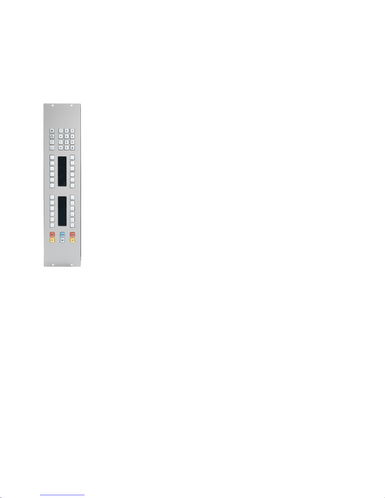
The VSet Console controller is an electronics package intended to be integrated into Audio consoles
or turrets, using metalwork provided by the console manufacturer or integrator. It is an attractive
and small Power over Ethernet (PoE) device with durable buttons and displays to allow Telos VX
control from the board operators position. A drawing package is available for those wishing to create
metalwork for the unit for their projects. Metalwork is available from most console manufacturers.
In addition to the Console Controller, there is a VSet desktop controller that provides control of the
system when no handset is needed or desired.
Integrating phone line selectors into the studio mixing console is an operator-pleasing feature that
is easy to accomplish in a networked studio. As this is written in December 2018, the following
consoles have VX-compatible call control modules available.
♦ Axia Fusion
♦ Axia Element Console
♦ Axia IQ and iQx Consoles
♦ Other manufacturers’ consoles by using the VSet Console Controller Electronics package
described above
CHAPTER 1
| 6
VX call screening software applications
PC based applications take studio phone operations to a higher plane. With many packages to choose from, most provide the
usual call screening functions for phone-active broadcasts – the PC interface can be used for all operations, including answering
and making calls, assigning priority, writing notes, etc. Using software may also reduce system cost, as no hardware phone need
be installed.
We’ve partnered with User Interface and broadcast workflow expert Broadcast Bionics to offer XScreen, a “cloud based” call
screening system. Basic operation is provided by a free version that is useful and fully capable. Though an optional paid version
allows extensive database options and a ever-growing list of other helpful features.
Since every stations needs and preferences are different, third party vendors such as Neogroupe, Arctic Palm and others offer
their own take on workflow, features and support options. Customizations are usually available for your own unique situation.
Please have a look at them all, as they each have much to offer.
Because Livewire audio is available at the PC via standard LW Driver software, a producer can readily record calls for later play.
These could be edited with a PC application running on the same machine. When a file has been produced, it can be sent to the
on-air studio over the network.
Page 16

WELCOME
Thus, depending on the software option chosen, the one Ethernet cable is used for:
♦ Telephone audio for the softphone, via Livewire.
♦ Livewire audio for the recording of calls.
♦ Transfer of recorded call files from the producer to the studio.
♦ Control messages between the PC and the VX for line selection, etc.
♦ Data messages such as call notes and IM between the producer and on-air studio.
♦ Database lookup of caller information, such as how many times they have called, the quality of their contribution,
whether they have won any contests, etc.
♦ Web browsing, email, chat, etc.
CHAPTER 1
| 7
The Livewire+ AOIP Network
You may be wondering what the “plus” means in Livewire+. It stands for the inclusion of the AES67 standard. Since traditional
Livewire predates AES67, you’ll know that a Livewire device is AES67-compliant if you see Livewire+. The VX system
components are linked via an Ethernet switch configured properly for multicast audio. In Livewire and AES67 enabled studios,
this will already be present and no additional switch may be needed. (unless we risk running out of ports and/or bandwidth on
the current switch) A list from Telos of currently tested and approved switches is available here:
https://www.telosalliance.com/Axia/What-Ethernet-Switches-has-Axia-Approved
It is important to understand that not all switches are created equal or are interchangeable. A qualified Livewire or AES67
capable switch is required to use Livewire or AES67. The switch must be properly configured to handle multicast audio packets
and clocking must be present on the network in order for Livewire or AES67 to work properly. Note that the VX Engine is not
capable of generating clocking for the AoIP network.
In a Livewire environment, the xNode audio interface generates the clock signal for the entire AoIP
network. So at least one xNode (or clock master) needs to be present in a Livewire setup. The
xNode (running up-to-date software) is also capable of creating PTP clocking for an AES67 network
although there are many options available in the marketplace for this specically. Keep in mind
that the VX Engines are not capable of generating clock for the network.
The Acoustic Echo Canceller
Fraunhofer’s acoustic echo canceler algorithm solves the problem of echo when a loudspeaker-to-microphone
acoustic path is required in the studio, such as when DJs prefer to record calls without using headphones or
when guests need to hear calls without headphones. The AEC in the Telos VX is a remarkable development. Its
performance is shockingly impressive, permitting very high loudspeaker volume with no noticeable return echo.
(If you’ve already experienced the Axia or Infinity intercom system, you know what we’re talking about…)
Page 17
INSTALLATION AND CONFIGURATION
2 Installation and Conguration
CHAPTER 2
| 8
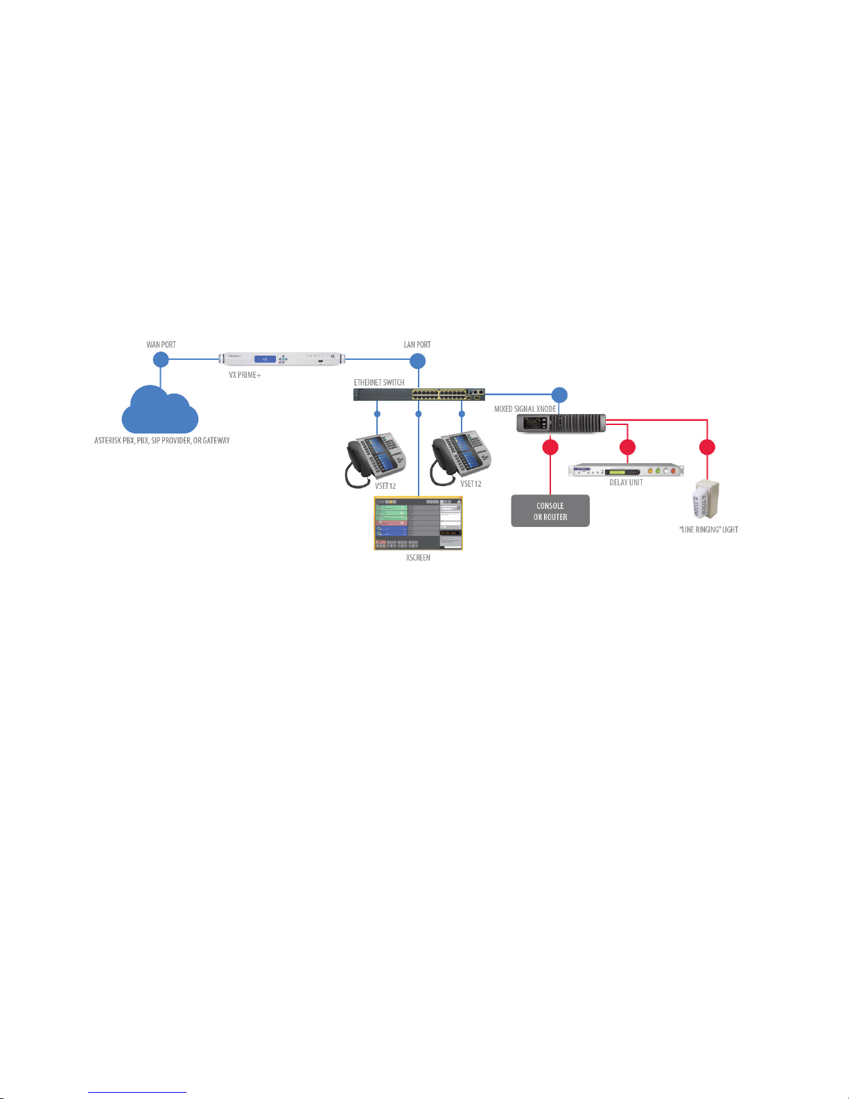
The diagram shows a generic installation that could be used in a typical studio. Two Ethernet ports are employed on the VX
engine to isolate the two networks that are present in this example. Livewire+ audio network is handled by the LAN port,
while SIP and/or Internet provided network is handled by the WAN port. Since it’s handling Livewire+ or AES67, the switch
connected to the LAN port must be configured for multicast audio. Meanwhile, the switch connected to the WAN port can be a
switch on your regular business network.
Telco lines enter two ways: From the PSTN via a PBX or from a SIP VoIP provider over an IP network, configured as endpoints.
In most PBXs these are called generic or third-party SIP extensions. xNodes provide analog, AES, and/or GPIO connections
to traditional studio equipment. The audio xNode also creates the clocking signal for the Livewire+ network. xNodes are
not needed when the studio equipment can accept AoIP natively and if there is already a clock source on the network. For an
example of this sort of installation, see Axia Console as VX Controller in Section 5.
Connecting to the PSTN: PBXs and Providers
‘PSTN’ is an acronym for ‘Public Switched Telephone Network’, the traditional telephone network is now made up of many
types of service providers, including the Legacy Utility Telco providers often called Local Exchange Carriers (or LECs),
Metro Ethernet providers (availability varies regionally), Fixed Wireless providers, Internet Telephone Service Providers
(who deliver service via the public Internet) and Competitive Local Exchange Carriers (CLECs). Most providers and PBX
manufacturers have adopted support for basic SIP trunks and also some provider services provisioned as “Endpoints”. They
also usually offer traditional interfaces like POTS, ISDN (PRI), often delivered over Ethernet or T1’s/E1’s as ‘last-mile’
connection technologies.
The VX system connects to Telco lines using industry standard SIP (Session Initiation Protocol). This means it is compatible
with a wide variety of VoIP services, gateways, and PBXs. Gateways can be used to interface legacy PSTN lines to SIP. We
discourage this as we’ve found them difficult to set up and maintain. They simply don’t provide the flexibility, audio quality
and reliability of an all-digital connection. There are other small drawbacks that wind up being surprises down the road like
when your callers receive a ring back signal instead of a busy signal when your lines are in pre-contest Block All mode. This
happens because there is no ‘off-hook’ condition in the SIP world.
Page 18

INSTALLATION AND CONFIGURATION
We’ve had the best results with full-up IP PBXs, like Asterisk and its derivatives, Cisco, Mitel, Avaya, and many others. Some
PBXs do have limitations in the number of “Third Party SIP devices” that they will support and there may be also be a variety of
other concerns, so it’s a good idea to arrange a call with your dealer and a Telos Applications Engineer before making any major
decisions.
Since VoIP phones are commonly used today for general office service. SIP lets you move calls between the office and studio
systems with no audio degradation and a common dial plan. A PBX such as Asterisk also adds additional capability, such as
automated-attendant, voicemail, call recording, logging, and time-based routing. With appropriate add-on interface cards,
Asterisk makes an excellent gateway to T1 and ISDN PRI Telco lines. It’s especially good for high volume contesting situations.
No longer a ‘niche’ offering as of 2019, SIP is now the standard for digital telephone service. The telephone service provider
and PBX platform are among the most important choices that you’ll make because you’ll be using it every day.
CHAPTER 2
| 9
What’s today’s equivalent of a ‘Line’?
Historically, a “line” meant a pair of wires from the telephone company with a phone number. It had simple DC (on/off
hook) and AC (ringing) signaling and audio all on the same pair. It could support a single call and would likely have a unique
telephone number. If set up to do so by the telco, it could provide “hunting service” to allow calls to move onto another POTS
line if the first one was busy. Today, everything has been un-bundled. Signaling is separate from voice channels and many
channels may use the telephone number at the same time. Another important distinction: VoIP audio is inherently “4 wire,”
that is separate transmit and receive. Telephony has evolved. So in the words of the Firesign Theater: “Everything that you
know is wrong.”
Let’s look at this new reality in two very different ways: From the talent/producer point of view, and from the telecom
engineers’ point of view.
The Talent side is the easiest to understand, so we’ll start there. Since this is the engineering side of the manual, I’ll let you in on
our dirty little secret. We are pretending to be old POTS lines on an old key system... for the user’s benefit, at least as far as the
workflow and feature set goes. We designed the system to look and feel familiar. Talent has different needs than the engineering
side of the house does. In short: They have an interface that they’ve used for years and we’ve re-created it for them, though with
many improvements. We do all of the complex stuff under the hood. Talent expects that each button on their Vset phone or
call controller is a “line.” VX works identically to a key system from 1955, except that it has modern push button (touch tone)
dialing, a color display with caller ID, and an easy way to move callers to air. It also has a skinnier ethernet type cord instead of
the traditional 25 pair (or worse) Amphenol plug ended cable(s).
In the original 2009 VX manual, Steve Church said “Users, blissfully unaware of all this, will undoubtedly continue with their
conditioned habit, referring to a certain caller as being on a particular line. Thus is the word ‘line’ destined to join ‘dial’ in a
peculiar departure from original meaning.” In fact, we still call the process by which you create a conference a “button mash.”
As we update this manual at the end of 2018, It’s clear that Steve has been proven right again.
From the Telecom Engineering perspective, it’s very useful to keep the elements that historically made up a “line” separate.
Using all of these elements intelligently can save us money and give us flexibility that we never knew in the old days.
The changes that VOIP has brought us have essentially moved the “Central office” right into our own facilities. We can now do
things today that only the telephone company could do 20 years ago. It also means that we pick up some of the responsibilities
for design and engineering and maintenance once take for granted as the domain of the “Telco.”
Things that we now care about:
SIP PBX / Server, this is a device that is designed to connect directly to a SIP Trunk or a legacy Trunk like a T1. It has
applications running to handle calls and dial plans. It will use this connection to the telco to provide extensions to endpoints
such as IP phones and the VX engine. We are most familiar with the Asterisk server. A lot of current providers can host the
PBX over the Internet, so it could be wise to see if the provider can offer a hosted PBX solution for the VX. If so, an additional
SIP Server will not be needed.
Page 19

INSTALLATION AND CONFIGURATION
CHAPTER 2
| 10
SIP Extensions, it’s important to assert that the VX is not a PBX. It is a collection of generic SIP endpoints that will need to
register to separate extensions off a SIP PBX. In some cases, the PBX is local and in others, the PBX is hosted by the provider.
In any case, the VX just registers to extensions. If a trunk is the only option, an Asterisk PBX or equivalent will be needed
on-site.
Registration, when a SIP endpoint subscribes to an extension for use, this is called a registration. The extensions used by
the VX are only registered to the PBX when the show referencing the extensions is called up in the VX studio. Multiple
registrations to the same extensions are possible in the VX Show, so we can use this to set up a roll-over or hunt group.
Direct Inward Dial (DID) numbers, sometimes called “Directory Numbers” - “Phone numbers” in plain English as spoken by
most humans. These can be dialed by users on the PSTN and Cellular networks.
Channels – Voice channels, like bearer channels in ISDN, each carries a call and uses 64-96kbs of bandwidth.
Trunk Groups – Groups of voice channels, sometimes it’s useful to artificially group calls to prevent calls to single number from
using all available voice channels, impacting other users (like “choking”).
Dial Plans – determine call routing for anything dialed. Ideally modeled after something familiar
Networks/Subnets – Because we’re dealing with real-time voice, low jitter must be maintained to keep calls sounding good.
This could involve separate LANS/VLANs, Quality of Service (QOS) settings, IP routing and even firewalls.
Codecs – we now have some control over what codecs are used. The PSTN as it exists in 2018 uses the g.711 codec to provide
“toll grade” (3.4 khz audio, 7 or 8 bit, companded), but private networks are not subject to this limitation. Many use the G.722
“HD Voice” codec for better voice quality, and availability is expanding. Some providers also use the aggressively compressed
G.729 codec which provides audio quality far inferior to the standard G.711 codec. Use of this codec should be avoided in
broadcast use. The VX does not support the G.729 codec due to quality concerns.
Bandwidth – We need to have enough low-jitter bandwidth continuously available to accommodate the expected number of
calls, including calls on hold, and a way to deal with additional calls that exceed our expectations. It need not be “really fast,”
but does need to be “steady” and able to deliver constant packet streams.
Each audio channel used by a call consumes 64-96 kbps.
Network Security – We must consider everything from proper operation to keeping the bad guys out. Please read our app-note
concerning this topic, which could fill many books by itself.
While this may all sound dramatic or daunting... It’s not that tough, and both providers and Telos can help. Remember, the
phone company used to manage all of this. Here’s an example of how it’s done today. Let’s say that you want to emulate the
existing studio phones:
5 Stations each with the following:
♦ 6 public call in numbers, request or contest lines
♦ 2 “Warm” lines for DJ business, guests or promotions
♦ 1 “Hotline” for the boss to call in on when they hear something that they don’t like
Page 20

INSTALLATION AND CONFIGURATION
CHAPTER 2
Here’s how we’d do it assuming ordinary levels of traffic for the typical music radio station:
Example Option 1 – Telephone company provided (typical)
From Telco or a CLEC We order:
♦ 1 or 2 T1’s carrying Primary Rate Interfaces (each carries 23 bearer channels and a D or Data channel that is used for call
setup). This will allow up to 46 simultaneous inbound or outbound calls through the system.
♦ A block of 20 DID numbers, initially to test with, then used later for utility things like Hot and Warm lines, IFB lines,
VOIP phones and voicemail boxes. Lets say that the telephone numbers are 311 555-2300 through 2320. DID numbers
are very inexpensive (pennies a month each), so don’t be afraid to order plenty.
♦ Ported “Vanity numbers” come later, after everything is all done. We only need the published numbers so... 5 of these (1
for each of the 5 stations)
♦ Expect this to take 15-90 days to provision and install.
From your distributor we order: (after consultation with a Telos Applications Engineer)
♦ Asterisk Machines with 4 port PRI cards (1 or 2 so you have a spare)
♦ Telos VX Enterprize or Prime+
♦ Telos xNodes if necessary
| 11
♦ Qualified Network switch for Livewire+ audio if not existing or too small
Here’s how it all works in practice once installed:
♦ A listener dials 311 555-2300 (your studio’s number).
♦ That number is recognized by Telco and is connected to a (PRI) trunk to your facility.
♦ The telco connects to your PBX and sends the DID number to the PBX on the far end of the Trunk.
♦ The PBX uses those digits to route the call further. (to the correct extension in most cases)
♦ The PBX rings the desired extension and causes ringback tone to be sent to the calling party until the called party answers.
♦ When the call is answered, a two-way audio path is cut through and the network is signaled that answer supervision
should be returned, charging the calling party of the call.
If there was more than one appearance of the called extension on a particular phone (more line buttons), more calls could be
passed to that extension. This would continue until no more channels were available, or an artificial limit in either the PBX,
Trunk or Telco would cause the “busy here” message to be sent back to the calling parties PBX or Central Office.
This means that:
1. We can now build our own hunt groups
2. We must consider the impact of getting more calls than we can handle.
3. We can change the hunt group size on the fly in most cases
Advantages to T1/PRI: “Safest” as the TDM PSTN network limits security threat exposure, and minimizes network design
complexity. Station may already have TDM connectivity present, reducing wait for new service. Traffic constraints “built in”
and understood already.
Disadvantages to T1/PRI: Legacy technology and connection service will ultimately become unavailable, slightly higher initial
and recurring costs.
Page 21

INSTALLATION AND CONFIGURATION
CHAPTER 2
Example Option 2: Provider provisioned as generic SIP endpoints
From the Provider we order:
♦ A circuit to carry our phone traffic. This could be anything from a T1 to a 10 mbps fiber circuit. This is a dedicated circuit
that has IP addresses that are not routable from the public Internet.
♦ The carrier will usually provide a router or Integrated Access Device (IAD) at your studio site. The termination will be
an RJ-45 ended ethernet jack. The length of time needed to get this will vary wildly, depending on your location and the
provider that you’re dealing with.
♦ A small block of DID numbers for testing and later utility use.
From your distributor we order: (after a consultation with a Telos Applications Engineer)
♦ Telos VX Enterprise or Prime+ Engine
♦ Telos xNodes if necessary
♦ Quaified Network switch for Livewire+ audio if not existing or too small
Here’s how it this all works in practice once installed:
♦ A listener dials 311 555-2300 (your studios number).
♦ That number is recognized by Telco and is connected to a (SIP) trunk to your facility.
| 12
♦ The telco connects to your PBX (off site) and sends the DID number to the PBX on the far end of the Trunk.
♦ Your provider’s PBX uses those digits to route the call further. (to the correct extension in most cases)
♦ The PBX rings the desired extension and causes ringback tone to be sent to the calling party until the called party answers.
♦ When the call is answered, a two-way audio path is cut through and the network is signaled that answer supervision
should be returned, charging the calling party of the call.
♦ When the call has ended, the stream is torn down and the customer billed.
If there was more than one appearance of the called extension on a particular phone (more line buttons), more calls could be
passed to that extension while in use. This would continue until no more channels were available, or an artificial limit in the
PBX, Trunk, or Telco would cause the “busy here” message to be sent back to the calling parties PBX or Central Office.
This means that:
1. We can now build our own hunt groups
2. We must consider the impact of getting more calls than we can handle.
3. We can change the hunt group size on the fly in most cases.
4. We must consider network engineering and security ramifications in design of the system because it’s delivered as IP.
Advantages: Fully protected from public Internet threats. Assured performance. It uses the most up to date technology.
Disadvantages: cost may be higher than Internet delivery
Page 22

INSTALLATION AND CONFIGURATION
CHAPTER 2
Example Option 3: Service delivered over the Public Internet
♦ From the Internet Service Provider (ISP) we order a circuit to be delivered on Ethernet to be used to telephony only.
Bandwidth, jitter, and a Service Level agreement should be taken into account.
♦ From the Internet Telephone Service Provider (ITSP) we need to order a trunk with an adequate number of channels and
a block of DID numbers.
♦ From your distributor we order: (after a consultation with a Telos Applications Engineer)
¸ Appropriately sized Asterisk PBX machine with enough Ethernet ports
¸ Telos VX Enterprise or Prime+ Engine
¸ Telos xNodes if necessary
¸ Qualified Network switch for Livewire+ audio if not existing or too small
Here’s how it this all works in practice once installed:
♦ A listener dials 311 555-2300 (your studios number).
♦ That number is recognized by Telco and is connected to a virtual (SIP) trunk to your facility across the public Internet.
♦ The telco connects to your Asterisk PBX over this connection and sends the DID number to the PBX on the far end of the Trunk.
| 13
♦ The PBX uses those digits to route the call further. (to the correct extension in most cases)
♦ The PBX rings the desired extension and causes ringback tone to be sent to the calling party until the called party answers.
♦ When the call is answered, a two-way audio path is cut through and the network is signaled that answer supervision
should be returned, charging the calling party of the call.
♦ When the call has ended, the stream is torn down and the customer billed.
If there was more than one appearance of the called extension on any particular phone (more line buttons), more calls could be
passed to that extension. This would continue until no more channels were available, or an artificial limit in the Asterisk PBX,
Trunk, or Telco would cause the “busy here” message to be sent back to the calling parties PBX or Central Office.
This means that:
1. We can now build our own hunt groups
2. We can change the hunt group size on the fly in most cases.
3. It is critical to fully consider network engineering and security ramifications in design of the system because it’s delivered
as IP and we are fully responsible for the security risks and performance of the system.
Advantages: Probable lowest monthly cost. Instant provisioning. (short lead time if adequate Internet circuit is present at
the site already).
Disadvantages: Riskiest type of installation for security. Riskiest type of installation for performance.
Fully considering and planning for proper Network security is absolutely critical when attaching
anything to the public Internet. This cannot be overstated. If not handled correctly, huge bills from
service providers, interruptions in service and very embarrassing public hacking episodes could be in
your future. Your employer counts on you to minimize their exposure to fraud and embarrassment.
Please take this seriously. Telos can help. Discuss your implementation with an Applications Engineer
before system deployment.
Page 23
INSTALLATION AND CONFIGURATION
CHAPTER 2
| 14
Livewire+ is used for audio I/O
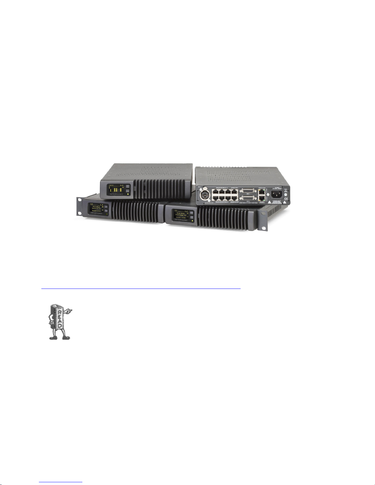
The Telos VX Enterprise and VX Prime+ accepts and generates many audio channels. Using Livewire+, it’s possible to make
them all available through a single simple Ethernet interface. A single Ethernet RJ-45 cable connects dozens of bi-directional
audio channels and GPIO command and status indications.
The VX Enterprise and Prime+ use Livewire+ for all audio I/O. For studios that are already Livewire or AES567-based, this
approach saves money and simplifies installation. When needed, traditional audio connections are provided via xNodes with
Livewire+ connectivity. These come in Analog and AES/EBU versions as well as a mixed signal version that incorporates both
AES and Analog and GPIO ports. Because they are networked, they can be located wherever it’s convenient, either in individual
studios or in a central rack room. Select the right mix and quantity of inputs and outputs that is most useful for your plant.
When doing this, keep in mind that the outputs of the xNodes are stereo and they can be configured for dual mono. The xNode
allows us to use the left channels and right channels separately for maximum flexibility. Don’t forget to include Program on
Hold inputs in your design when planning for an xNode purchase.
Keep in mind also that both Livewire+ and AES67 require a specially configured Ethernet switch to work properly. A list from
Telos of tested and qualified switches and configurations is available on our website here:
https://www.telosalliance.com/Axia/What-Ethernet-Switches-has-Axia-Approved
Depending on its conguration, A VX Engine can generate enough AoIP data to ll a 100 mbps
ethernet “pipe”. You should always connect Gigabit Ethernet switch ports to the LAN (Livewire) port
on the VX. Don’t forget the switch need to be properly congured for multicast audio.
Page 24

INSTALLATION AND CONFIGURATION
CHAPTER 2
| 15
Step-By-Step Summary
There is a lot of information in the pages that follow. Here’s a high level and simplified view of what you need to do to get your
VX system up and running:
1. If you will not be using an existing Livewire or AES67 network to support the VX, install the Ethernet switch, or switches.
Configure these for use with the Livewire or AES67 as outlined in the guidelines stated in Telos’ guides for switch
configuration using the console cable. You can find proper switch configurations for Livewire on our website. A clock
source will also be needed for this network. Enable and configure the WAN port on your VX engine appropriately with
addresses and credentials provided by your telephone carrier or IT department.
2. Assign IP addresses to all of your Livewire/AES67 devices and test connectivity.
3. Install and configure your PBX if you will be using one to interface to POTS, ISDN, or T1 PSTN lines. If you will be using
VoIP trunking for your Telco connection, get it connected and gather the IP and registration credentials.
4. Get a web browser going and do the system configuration.
5. Move on to install and configure the Vset phones and call screening software applications (if applicable). Then to any
other controllers you have in your system, such as integrated console controller modules.
6. Test your system thoroughly
Racking Instructions
Before we start
You should inspect the box the chassis was shipped in and note if it was damaged in any way. If the chassis itself shows damage
you should file a damage claim with the carrier who delivered it.
The VX Enterprise and VX Prime Plus are packed into a single rack space using modern server chassis technology. There
is a special method to racking the chassis using the supplied glide rails, so please read this section completely before
commissioning your new system. Decide on a suitable location for the rack unit that will hold your chassis. It should be
situated in a clean, dust-free area that is well ventilated. Avoid areas where heat, electrical noise and electromagnetic fields are
generated. You will also need it placed near a grounded power outlet and always ensure the rack is stable before mounting into
or extending a component from the rack.
The system includes two sets of glide-rail assemblies. These make up one half of the mounting hardware. The other half is
already mounted to the chassis. The glides need to be installed into the rack system before the chassis is mounted. The front
panel is not designed to support the chassis. DO NOT use the holes on the front panel by themselves to mount the chassis to
the rack. Over time, this will cause mechanical stress and damage the chassis. Leave approximately 30 inches of clearance in
the front and back of the rack to allow for sufficient airflow and ease in servicing. It should be mounted in the rack so that the
amount of airflow required for safe operation is not compromised. We recommend at leaving least 1 empty rack space above
and below the chassis for proper airflow.
System grounding
A reliable ground must be maintained at all times. To ensure this, the rack itself should be grounded. Particular attention
should be given to power supply connections other than the direct connections to the branch circuit (i.e. the use of power
strips, etc.)
Page 25
INSTALLATION AND CONFIGURATION
CHAPTER 2
| 16
Installation
Since there are a variety of rack units on the market, assembly procedures might differ slightly. You should also refer to the
installation instructions that came with the rack you are using. The glide-rails included with the VX Enterprise and Prime Plus
will fit a rack between 26” and 33” deep.
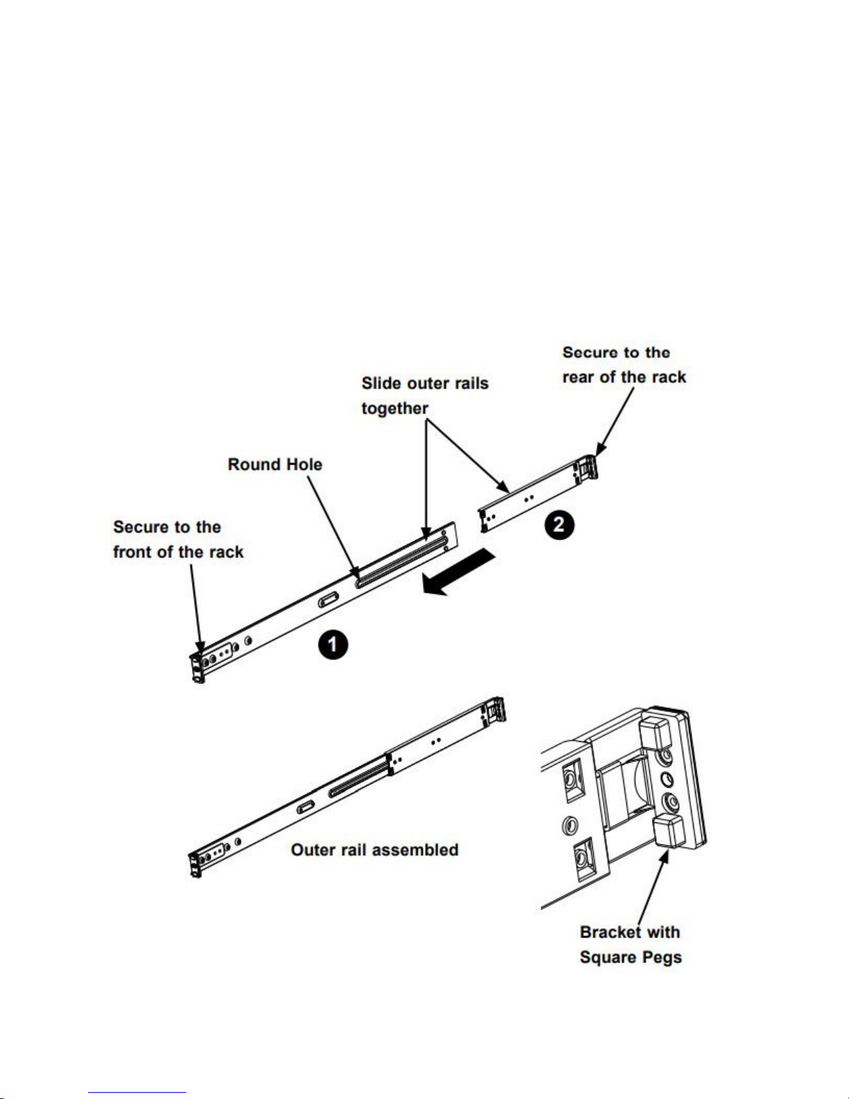
The fixed inner portion of the glides with their locking tabs are already installed onto the chassis, so the assembly of the outer
portion is all that’s needed. The outer glide rails attach to the rack and hold the chassis in place. Each end of the assembled
outer glide rail includes a bracket with square pegs to fit into your rack holes. If you have an older rack with round holes, these
brackets must be removed, and you must use screws to secure the glide rail to the rack.
Page 26
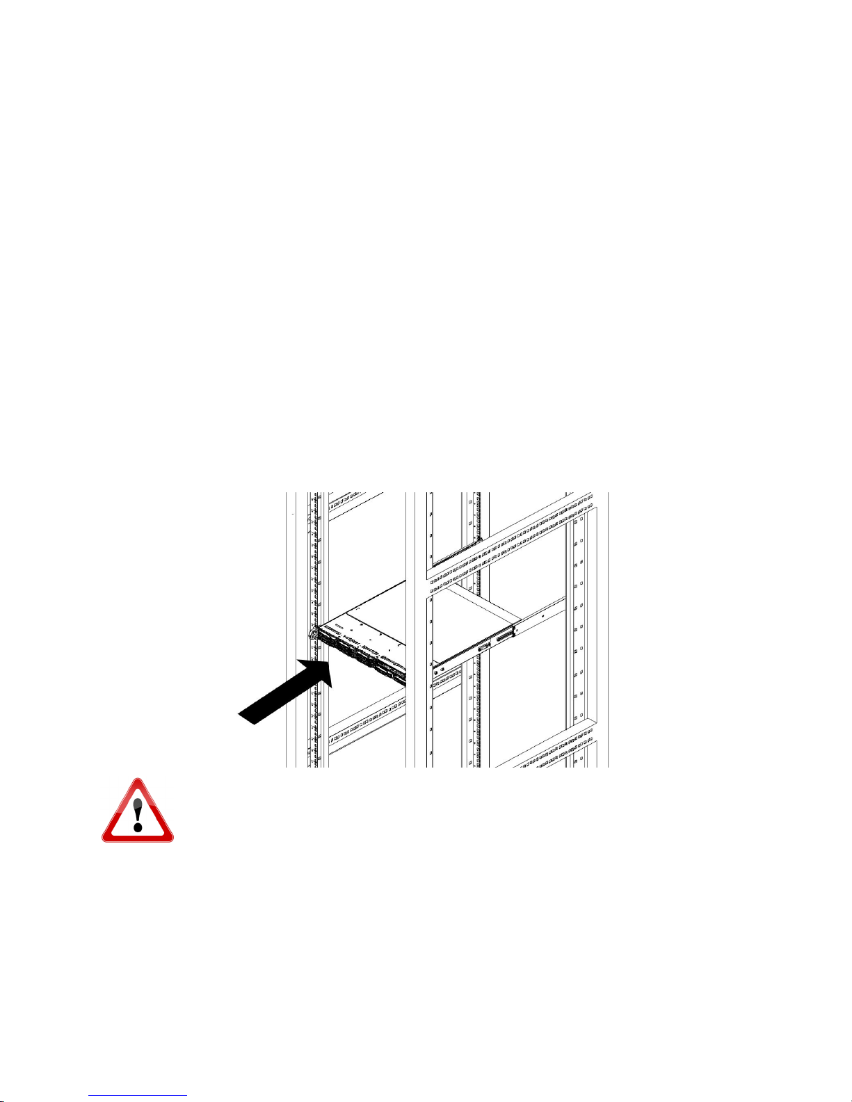
INSTALLATION AND CONFIGURATION
1. Identify the left and right outer glide rails by examining the ends, which bend outward. Match the left front outer glide
rail with the left rear outer glide rail and the same for the right rails.
2. Align the round post in the rear rail (2) with the round hole at the end of the slot in the front rail (1), and slide the front
section into the rear section.
3. Align the square pegs on the front end of the rail with the square holes on the front of the rack. Push the rail into the rack
until the quick release bracket snaps into place, securing the rail to the rack ---or--- remove the filler bracket with the
square pegs and use the oval screw holes to mount the angle to the front rack rail. Keep the glide-rail horizontal.
4. Adjust the glide-rail to reach just past the full depth of your rack.
5. Align the square pegs on the rear end of the glide to the holes on the rack and push the glide rail into the rack until the
quick release bracket snaps into place, securing the rail to the rack. ---or--- Remove the filler bracket with the square pegs
and use the screw-holes to mount the glide rail to the rear rack rail.
6. Repeat the procedure for the other outer glide rail assembly.
7. Align the inner portions of the glides mounted to the chassis with the outer portion of the glides that you have just
installed in the rack and slide the chassis into position. The locking tabs will engage when they reach the proper position.
8. The center holes in the front panel/glide rails can be used to lock the chassis into position. They can then be removed if
the unit needs to slide out on its glides for servicing.
CHAPTER 2
| 17
WARNING: Never pick up the chassis by the front handles. The handles are designed to pull the
chassis out on the glide rails for servicing only. Glide-rail mounted equipment is not to be used as a
rack shelf or a workspace.
Page 27
INSTALLATION AND CONFIGURATION
CHAPTER 2
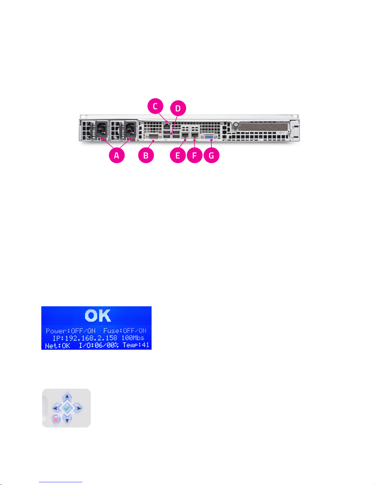
Rear Panel Connections
1. Power Inputs: These are dual, hot-swappable, 400W OEM supplies that will take voltages from 100VAC to 240VAC at
both 50 and 60 cycles per second. To use the system with one supply, remove the unused one from the chassis using the
lever below the IEC socket. This will disable any alarms.
2. RS-232: This is for development and diagnostic purposes only.
3. IPMI Control Port: This Intelligent Platform Management Interface is a connection for development purposes only.
4. USB Ports: These are serial ports used for development and factory production only.
5. WAN port: This port receives the connection to the SIP/ISP accessible network. In cases where a local SIP PBX is used,
the WAN port may connect directly to the PBX.
6. LAN port: This port receives the connection to the Livewire+ network.
7. VGA port: This is used for development and diagnostic purposes only.
| 18
Getting the VX on the Network(s)
The Engine front panel display gives at-a-glance status information. The
main status screen is pictured here. It shows the IP number for the LAN
(Livewire) port, its connection speed and status. The overall status and CPU
temperature are also indicated. Under normal conditions, you’ll see what we
call “The big OK.”
If you don’t see “The big OK”, there is an indication on the front panel and web GUI (system page) that will indicate what’s
wrong. It usually means a power supply is not plugged in, an Ethernet cable is disconnected, or the engine can’t find a Livewire
or PTP clock on the AoIP network. You may not see an “OK” until the rest of the VX’s network config is set up. This is actually
OK! Keep going.
To enter the menu on the front panel, press the enter [ü] key in the center of the direction pad and
navigate using the arrow keys. From the main menu, go to IP Settings and configure the IP address and
netmask of the LAN port, activate the WAN port, and give it an IP address and netmask. When changes
are applied the system will ask you to reboot. Changes take effect after the reboot is finished.
Page 28
INSTALLATION AND CONFIGURATION
CHAPTER 2
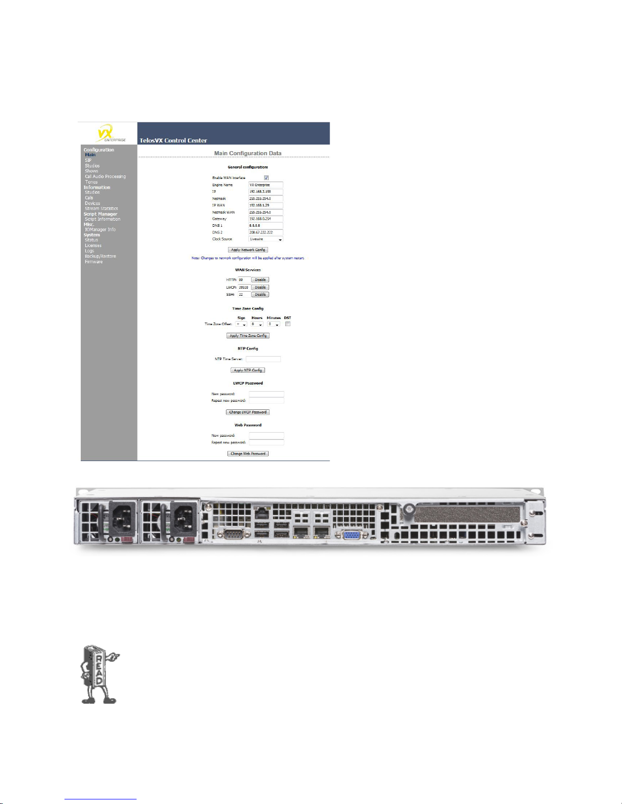
Once you get the VX Engine on a network, you’ll want
to finish configuring the system using the Web
interface. This is done using a browser on the same
network as the VX’s LAN port using the IP address
configured at the front panel. The MAIN
CONFIGURATION page is where we’ll finish the network
configuration. In the General Configuration section,
you can enable the WAN port and give it an IP address,
subnet mask, gateway, and DNS IPs, finalizing the WAN
network setup. This is also where you will also select
the type of AoIP clock you will be using on the LAN
network. The choices are “PTP” and “Livewire.” You
may also change the host name and the LAN (Livewire)
IP address from here too. Once you have made changes
to this page, the system will need a reboot. We will go
over the Web GUI in more detail a few pages later.
| 19
The VX Engine has two RJ-45 Ethernet jacks on the rear panel. Both are 100/1000 auto-speed and duplex setting. The WAN
port is to be connected to the business network or the network containing the SIP server. The LAN port is for AoIP audio and
everything else such as PCs used for web-based configuration, VSet controllers, producer PCs, and console controllers. This
can be connected to an existing Livewire network or to a new dedicated network that you create to serve only the VX system.
Remember the switch managing the AoIP network must be qualified for Livewire or AES67 and must be configured to handle
the multicast audio packets present on the network. A complete list of Telos approved switches is available on our website.
In order for AoIP audio to work, there must be one device capable of supplying clocking on the AoIP
network. In a Livewire+ environment, this device is the xNode. While the Powerstatoin and QOR
engine can generate regular Livewire clocking, the xNode is Livewire+ and is therefore AES67
compliant. Because of this, the xNode can also act as a PTP clock master on an AES67 network.
Page 29
INSTALLATION AND CONFIGURATION
An appeal of the Ethernet/IP approach to building studios is that you can make them as simple or elaborate as your needs
require. The components of a VX system: the Engine, VSet phones and controllers, console controllers, and PCs are networked
together using standard, off-the-shelf Ethernet switches properly configured for Livewire or AES67. A small VX system might
have only a single Ethernet switch as the network infrastructure, while a large full-facility setup could have dozens of switches
and an IP router or two.
All Ethernet switches are not created equal! The Ethernet switch used by the Engine’s LAN port must
be Telos Approved and Livewire/AES67 capable. That is, it needs to correctly support multicast, IGMP
and QOS. Switches that are not multicast-capable usually (most consumer unmanaged switches)
ood with multicast trac such as Livewire audio streams to all ports, potentially overwhelming
devices like PCs and printers.
WARNING: Never plug the VX LAN port into an oce or VOIP phone network after Livewire outputs
are enabled! Nothing oods an entire network quite like unmanaged multicast trac.
Multicast-capable and enabled switches will not propagate the Livewire traffic to ports that are not subscribed to a particular
audio channel. Thus, blocking the high-volume traffic from places where it isn’t wanted. An example of a Livewire / AES67
switch is the Cisco 2960G or another from that family. The Telos xSwitch and the built-in switch that is part of the Axia
PowerStation and QoR Engine is also suitable for this. Of course, the VX and Axia consoles were designed to work smoothly
together.
CHAPTER 2
| 20
For the current list of approved switches please visit:
https://www.telosalliance.com/Axia/What-Ethernet-Switches-has-Axia-Approved
Livewire traffic can easily overwhelm a network that isn’t designed for it. The WAN (Wide Area Network) port is isolated
from the Livewire port and thus provides a kind of AoIP firewall, ensuring that no multicast traffic can pass to the Wide Area
Network, often connected to a business network to access VoIP.
Out of the box, the defaults for the network connections are:
♦ The WAN port is disabled. To use it, you must enable it as described above from the front panel or the MAIN
configuration page of the VX’s web interface.
♦ All services – HTTP Web access, SIP/ VOIP and Vset audio and the Livewire Control Protocol are available on the WAN
port when enabled from the VX Web GUI. They are disabled by default.
♦ No Livewire inputs or outputs are assigned or enabled. You do this on the Studios configuration page described a few
pages later.
Page 30

INSTALLATION AND CONFIGURATION
CHAPTER 2
| 21
VSet Installation
VSets are normally connected to the Livewire/LAN Engine port via the Ethernet switch linked to this port. There are separate
manuals covering the VSets that have more information in them than this manual. You can find them on our website here:
https://www.telosalliance.com/Telos/Telos-VSet
The VSet is powered over the Ethernet connection. This is 48 volts DC according the PoE (Power over Ethernet) standard.
The Vset’s power consumption is 15.4W. Power may be supplied by the standard PoE injector we include with each Vset, or
it can come from an PoE equipped Ethernet switch. If a PoE switch is used, ensure that the Ethernet cabling is not so long that
it causes too much voltage drop. Some Axia products, such as the PowerStation, iQ QOR Engine, and xSwitch also have ports
that provide PoE.
♦ Connect the Ethernet cable and confirm that that the LEDs near the jack are indicating correctly. The green LED (link
light) should be on solidly, showing a good connection. The yellow LED (data) should be flashing, indicating data flow.
♦ After a few seconds, the LCD backlighting comes on, then the screens should come to life as the Vset “boots up”. If they
do not, the likely problem is the PoE supply or an ethernet cable issue.
♦ Press the Menu button and then navigate to the Setup Menu . (On the Vset 6, press the “more” button to display
additional options including Setup.) Press and hold the button to the left of Setup Menu key for 3-5 seconds and then
release it to access the setup menu for changes. This “press and hold” feature will make it less likely for unauthorized
users to make changes that could disrupt normal operation. Just pressing it and releasing it (without holding it) will only
show you the IP address and will not let you change it.
1. Enter the IP address that you are assigning to the phone and press the green “Go” button.
2. Do the same for the netmask value. (Most often, this may be kept at the default 255.255.255.0)
3. Do not enter anything in the “Vset Gateway” field unless directed to do so by Telos Support. The Vset will operate on the
Livewire network and will not need to be routed anywhere unless you have an unusual or custom installation.
After selecting the engine, you might see ‘Connected to...” for a moment at the bottom of the Vset screen.
If the Vset operation seems unusually sluggish or unreliable, check your network to be sure that your
switch was set up for Livewire operation according to the app note for your switch.
System Conguration
Before we get into the actual configuration of the system, let’s discuss some of the different options available to you. The VX is a
very flexible phone system, so it will be a good idea to consider these options before diving into the configuration for the first time.
Selectable and Fixed Lines Dened
The VX supports what we call ‘Selectable’ and ‘Fixed’ lines. It is possible to have a mix of each type in any studio.
If you’re in North America, you’ll most likely want to use Selectable lines. Fixed lines are more commonly used in Europe. With
a fixed line, a specific telephone number is always associated with a particular button on the VSet phone and a specific fader on
the console. It is as if each line has its own hybrid. This allows VIP numbers and hotlines to have fixed and dedicated console
faders. Auto answer is also an option for fixed lines giving them remote IFB and intercom capabilities.
Multiple calls that are assigned to a single fader have individual hybrids/processing and are actively conferenced within the VX
Engine using an internal mix-minus matrix. Calls assigned to different faders would normally be conferenced via a mix-minus
matrix of some kind within the studio mixing console.
Page 31

INSTALLATION AND CONFIGURATION
Selectable lines use an operation style like traditional Telos systems, where there was a line selector before the hybrid or
hybrids. Most operators are used to the operating paradigm that the old “1A2” key phones made so prevalent, where you have
a column of buttons and pressing one takes a line and drops the one that was active before. For that reason, we have kept this
operation style as the default for the VX. We have also kept the Telos “lock” function that lets an operator conference multiple
lines and keep VIP callers on-air while coming and going with others. This also allows selective holding and dropping of
conferenced lines.
Do keep in mind that all faders (fixed or selectable) count against the maximum total number of 24. ‘Selectable’ is generally a
more efficient use of VX system resources.
Speaking of conferencing and 1A2 key systems, we call the process of conferencing calls using the
Lock function a “button mash.” This term comes from the 1A2 days when you needed to “mash”
multiple line buttons down on your key phone so that they latch down together. The result was a
conference of those lines on your key phone’s handset. This term has faded away in the wake of
modern phone systems, but we’ve held on to this term along with “dial,” “hyrbid,” and “line” to keep
the workow easy to comprehend by users of the system.
CHAPTER 2
| 22
Studios and Shows Dened
The VX system can support multiple studios and can share lines among them.
A “studio” is a collection of controllers and audio or GPIO IO that are used together, usually to serve one studio: Vsets, Call
screening applications on PCs, Audio input and output Nodes (if any), GPIO interfaces (if any), and console controllers (if any).
A show is a pre-configured profile that can be selected by users. It assigns the lines to buttons. This is the mechanism that lets
you easily move groups of lines from studio to studio. Studios and shows are configured via the web interface to the VX Engine.
Interfaces such as the VSet and the VX Producer let operators select the studio and show they want to use.
Conguration Web Pages
To access the configuration Web pages, find or connect a PC to the network that the VX Engine’s LAN port is connected to.
Load a web browser and open a connection to the VX by entering the IP address of the Engine’s LAN port into the browser
address field.
When prompted for a username and password, use the following:
Username: user
Password:
Note that there is no password, so leave the password field blank.
Page 32
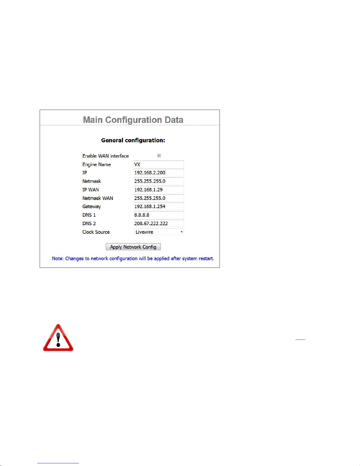
INSTALLATION AND CONFIGURATION
CHAPTER 2
| 23
Main Conguration Page
This is the page you will see upon initial connection to the engines Web GUI. Select the pages you want by clicking on the menu
at the left side of the page. If this is a new installation, start with the Main page, then move to the SIP page, the Studios page, and
then on to the Shows page. The purpose of each of the pages and how to use them is detailed below.
Engine Name assigns the host name for this VX Engine.
If you don’t want to use the default IP, Netmask, and Gateway, enter them here. IP addresses can be entered for both the LAN
and WAN ports. The WAN port must be enabled for its option fields to appear on your display. The Gateway is the “device” on
the WAN port’s network that provides routing to another network such as the Internet. It is required if the NTP and SIP server
or PBX is housed on another network such as over the Internet or sometimes over a dedicated connection. Its IP address goes
here and should be within the WAN port’s subnet.
WARNING: Do not assign the “gateway” address to the Livewire network, as Livewire is not routable.
What this means is if your LAN address is 192.168.2.200, make sure that the WAN gateway does NOT
start with 192.168.2.XXX
DNS 1 & 2 are used to tell the VX where the Domain Name Servers are located on your network or over the Internet. 8.8.8.8
is the DNS housed at Google.com so it’s always a good one to use. DNSs are required for domain name lookups when URLs
are used instead of IP addresses in SIP configurations. Just incase you’re unfamiliar; this is the “device” on the Internet that
translates a URL like google.com to an IP address like 172.217.14.10. So a problem here will keep your VX from connecting to
your server if it requires a URL instead of an IP address.
Clock Source tells the VS what kind of clock is present on the AoIP network. The options are Livewire and PTP.
Any changes to the network configuration need to be followed by a system reboot in order for the changes to take effect.
Page 33
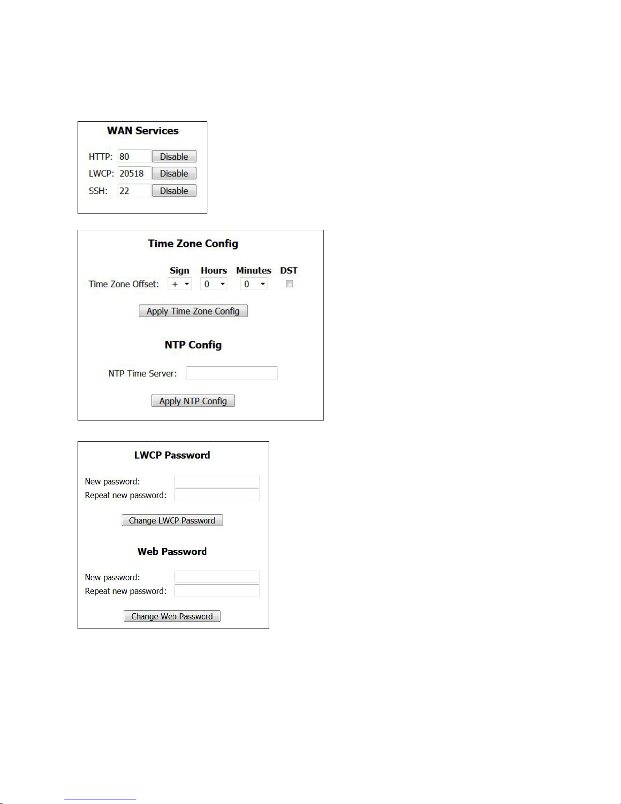
INSTALLATION AND CONFIGURATION
WAN Services chooses which services are available on the WAN port. HTTP is for web
access, LWCP is for controllers, and SSH is shell access to the Linux OS in the Engine.
SIP/VoIP are always enabled on the WAN port when the port is enabled. The port
numbers displayed in the fields are the defaults for the system and can be changed to
customized values depending on the needs of your WAN network. These functions are
disabled by default.
CHAPTER 2
NTP (Network Time Protocol) is the Internet standard
for keeping devices synchronized to the correct time and
date. The VX uses this to have accurate timestamps for
logged events. Enter the IP number for the NTP server
here An NTP server must be accessible on either the LAN
or WAN port. The VX automatically finds the correct
port. If the NTP server is outside of both the LAN and
WAN local network segments, the gateway address must
be set, and the NTP server must be reachable from the
WAN. You can use a domain name if a DNS server is
configured and accessible. Under NTP Config are the
settings for your location. A green check mark will appear
after you enter and accept your NTP server setting, and
the server connection is successful. If there is an Asterisk
server present on the network, NTP is often supplied by it
and can be used as your time source.
| 24
Web Username and Password. Used for web access for configuration
and monitoring. Username is always user and there is no default
password, so the password field is left blank.
LWCP Password. LWCP stands for Livewire Control Protocol, the way
controllers communicate with the VX Engine. A password can be used
to secure the Engine from being controlled by unauthorized devices.
The Vset, for example, uses this password. By default, there is no
password, so the field is left blank. We recommend not setting a
password.
Default Username, Password, and IP settings
We put this info here under its own header, just to make it easy for you
to find when surfing the table of contents…
VX Web GUI username/Password
Username: user
Password: ß No password. Leave the field blank.
Network Interface default settings
♦ “LAN” (Livewire) IP: 192.168.2.200
♦ Netmask: 255.255.255.0
♦ State for the WAN connection is OFF by default, with no IP set.
♦ Default “Gateway” address should be gateway for WAN address only
Page 34

INSTALLATION AND CONFIGURATION
Network TCP and UDP ports used by the system
♦ Active ports on WAN interface by default are:
♦ 5004 - DSP Engine
♦ 40000-41000 handset audio for Vsets and call screening software
♦ 62000 through 62513 - RTP
♦ 5060 – SIP
♦ 10000-20000 - SIP RTP
♦ 8080 – WAN port HTTP Server (disabled by default, change with GUI)
♦ 1022 – WAN port SSH Server (disabled by default, change with GUI)
♦ 20518 – Livewire Control Protocol (LWCP disabled by default, change with GUI)
A computer on the same subnet as the ‘Network’ (Livewire) interface, (example 192.168.2.100) could
log into the VX with this URL: http://192.168.2.200 while a computer on the same subnet as the WAN
interface (example 192.168.5.2) could log on using http://192.168.5.200:8080 once the port is
activated.
CHAPTER 2
| 25
Default user name is: user
Default password is: ___________ (blank, there is no password)
Passwords are case sensitive
If you change any of these, you might want to write the new values into this manual, here or elsewhere.
SIP Conguration Page
The SIP configuration page shows the global SIP settings, along with a list of all SIP
servers that your VX is configured to use. You can configure one or many SIP servers.
The Add New field at the bottom of the page lets you to add another server. A server
can not be deleted if a show configuration has it in use. The Lines column shows the
number of lines that are explicitly configured, and the total number of line positions
in shows using this server. Clicking on the link with the server name will bring you to
the server configuration page.
Enabling SRV Lookups makes the VX to strictly follow the SIP standard when
resolving domain names. This feature is not widely used and can be left unchecked
unless required by the SIP provider.
Page 35
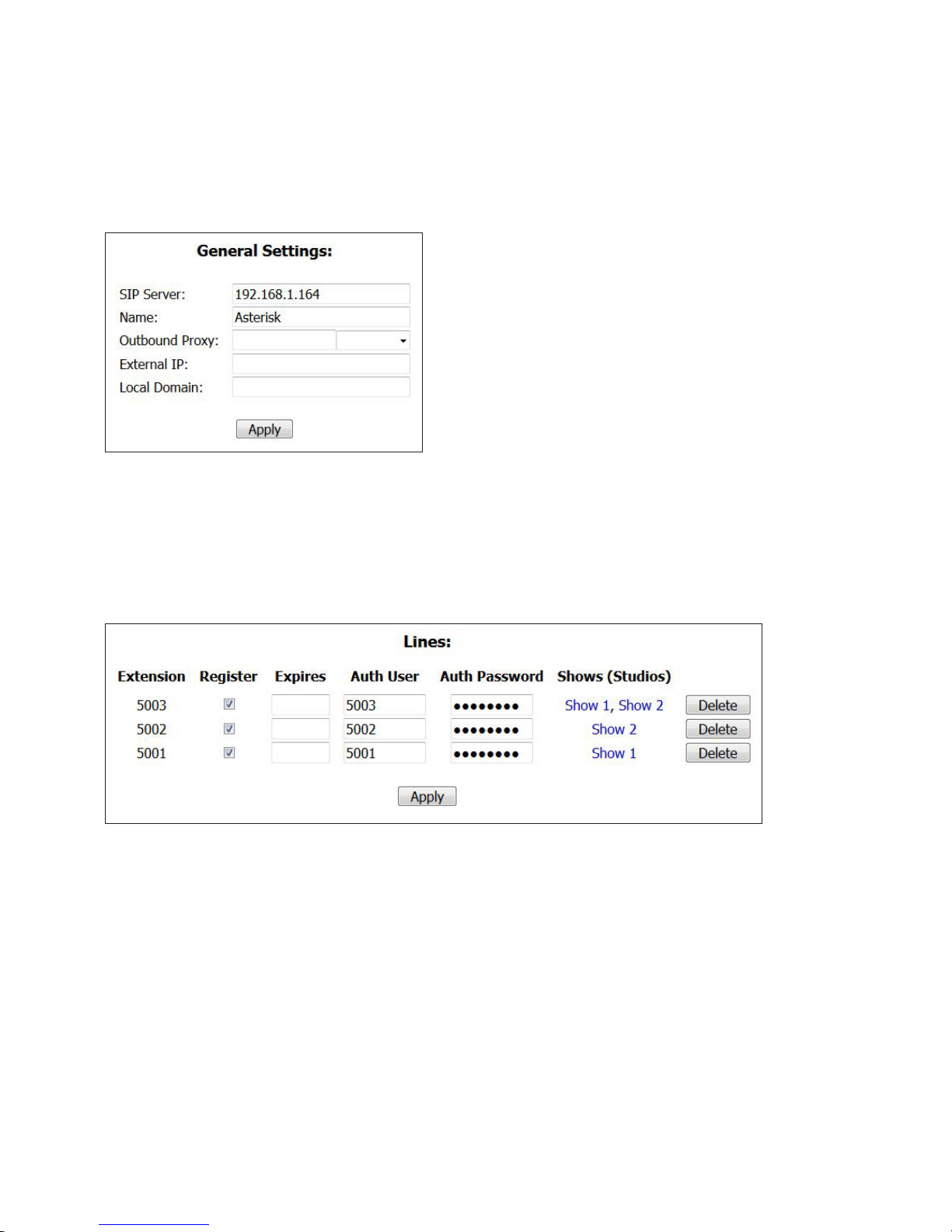
INSTALLATION AND CONFIGURATION
CHAPTER 2
| 26
SIP Server Conguration
When a server is selected from the SIP page’s list, you will be taken to
that SIP server’s configuration page. Please note that to change the
server settings you have to unload any shows referencing the server. It
is not possible to change them while the server is in active use.
The SIP Server field houses the IP address or URL of the SIP server. If
you are using a URL, make sure you have a valid DNS configured in
your VX’s MAIN page.
You can also assign a more descriptive Name to the server, which
will be then shown in place of the server address in subsequent
configuration pages. As it is used for display purposes only, it can be
anything you want, like ‘Asterisk.’
The Outbound Proxy field is for use when your SIP provider has specified an outbound proxy IP address for you to use for your
service. This will not be required for all SIP server configurations.
The External IP field is available just in case port forwarding is needed at a router (or Gateway). If port forwarding is required
at the NAT router of the WAN network, this is where the public facing IP address of the router should be entered. More on this
later.
If your server is part of a Local Domain, enter that here, otherwise leave it empty as well.
In this configuration page, the extensions to be registered by the show configuration are referenced here. The Extension and
server together make up the SIP address of a line. Each must be unique, as in the context of SIP the “line” is the address (and
associated configuration). In our example extension [email protected] is the SIP address of line (extension) 5002. You
can also see that extension 5002 is referenced by Show 2 in this example. It is not in use because a studio is not listed and we
can edit the extension. If a Studio had Show 2 in use, the extension would be un-editable and that Studio would be listed in
parentheses next to the Show.
Page 36
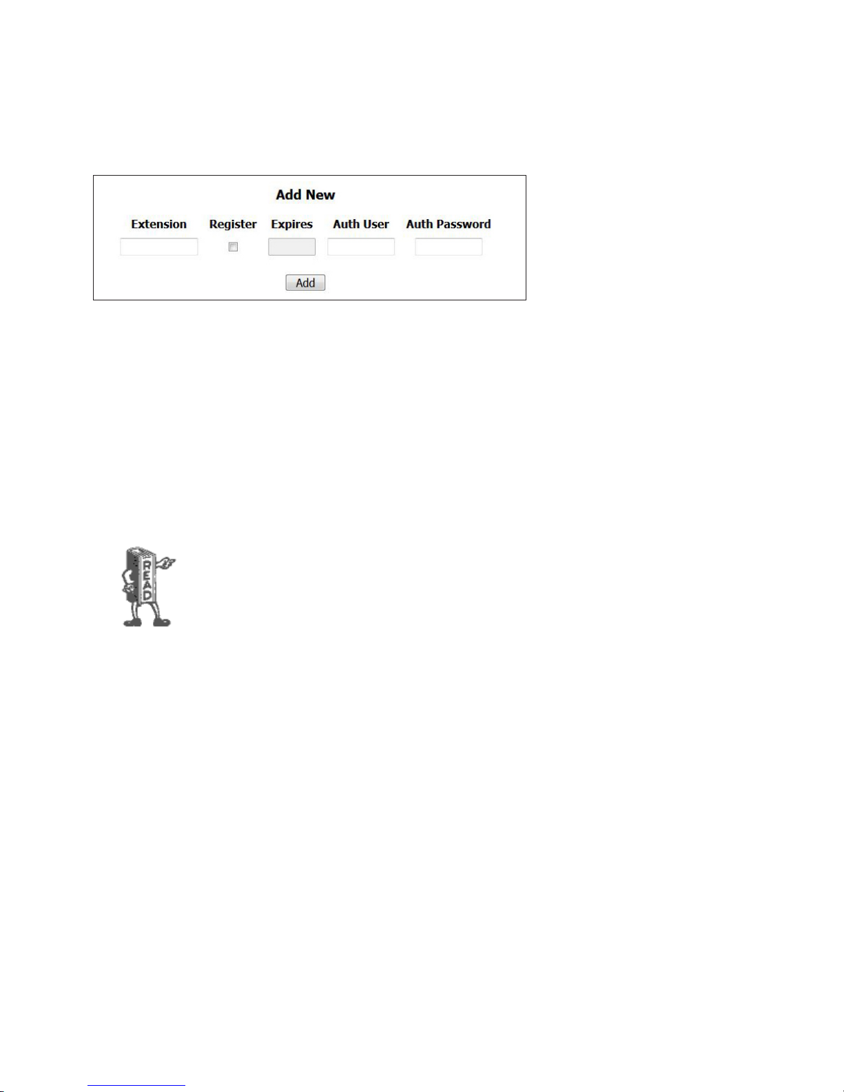
INSTALLATION AND CONFIGURATION
If extensions and shows referencing them are already configured in your VX, your SIP Server page will look like the one
pictured here with the extensions and shows listed. Otherwise, you will be greeted with the Add New fields. The information
entered into these fields is determined by the configuration of the SIP server or PBX. Check the appendix for setting up an
extension in Asterisk. There you can see how we set up extensions 5001, 5002, and 5003.
Enter the credentials for a generic (or third party) SIP extension into the Extension field. In our example, we are using an
Asterisk PBX which handles extensions as numbers. Depending on your service, extensions could be numerical as well as
alphabetical.
Check the Register checkbox to allow the VX to register to the extension.
The data entered into the remaining Expires, Auth User, and Auth Password are determined by the SIP Server or PBX. Auth
Password is sometimes (and in the case of Asterisk) called “Secret” in their configurations.
CHAPTER 2
| 27
We recommend conguring SIP extensions as Endpoints that use registration. This makes network
troubleshooting easier and tests the entire IP connection to the SIP server. Be sure to tick the
Register checkbox. This will make the VX register with the server (meaning essentially, log in)
whenever a show referencing this line is active, The Expires eld lets you to change the interval (in
seconds) in which the VX will refresh its registration. When left empty, the server and VX will
negotiate for a reasonable default, usually one hour. As a general rule, don’t populate the Expires
eld unless Telos support recommends it to solve a specic problem. The other two elds allow
you to set the password and change the “Auth” user name used for authentication. Auth User, is
generally the same as the extension number on most PBX’s. (and in our example)
For quick access to the configuration, you can use the Cong link in the Show configuration page. Each position with correct
configuration has a link marked ‘»’ next to it. Clicking on it will bring you to the corresponding server configuration page, with
the matching line configuration highlighted. In case the line is not configured, the extension field for adding it will be filled in
from the show.
Page 37

INSTALLATION AND CONFIGURATION
CHAPTER 2
| 28
SIP and Network Address Translation (NAT)
As SIP messages list IP addresses and ports used to transmit audio (RTP), it doesn’t work well if the client is in a private LAN
but needs to communicate with a SIP provider outside of the LAN. As messages pass through the router, it translates addresses
in IP headers, but not the SIP message itself, giving the provider wrong connection info.
Many SIP providers use clever hacks to work around this limitation without any additional support from the client. If you are
connecting VX to a SIP provider that doesn’t have such service, don’t worry - all is not lost, as VX has basic NAT support built-in.
For full details of using VX behind a NAT router, please see the App note on that topic.
Regarding Codecs and SIP
Some details regarding the VX’s SIP implementation:
♦ As of the time of writing, the VX supports the G.711 (alaw or ulaw companding) and G.722 codecs. G.711 is the usual
PSTN codec, so ISDN or T1 connections will not suffer any transcoding loss. SIP automatically negotiates and selects a
codec that is supported by both ends. Implements RFC 3261 standard (but see below)
The G.722 codec is the same codec known to broadcasters from the pre-MPEG days of ISDN remotes. It has 7kHz audio
bandwidth, opening the door to much better than usual speech quality, often from mobile handsets using softphone apps
and connecting via internet. When there is reliable and sufficient IP bandwidth, audio quality from mobile phones can be
much improved compared to the usual fuzztone. The Acrobits or Bria apps work well with G.722.
On Windows and Linux, the free Ekiga VoIP softphone works fine.
♦ Be aware that there are several other “G.722 codecs” that are proprietary for use with certain brands of SIP business
telephone sets or mobile devices. These are not currently supported by the VX. The most common G.722 codec is
supported. We may add other codecs to the VX over time with sufficient interest from customers.
For both of the above, you need to force the use of the G.722 codec by enabling it and disabling the others (in the PBX or
providers dashboard). On the VX side there is no setting for this, everything is handled automatically during normal SIP
codec negotiation. Following the usual procedure, the codec choice is made by the caller and conveyed in the SIP Invite
message and procedure.
SIP-connected G.722 audio is not via the PSTN, so the VX Engine would need to connect to an Asterisk system or G.722
capable service provider, properly firewalled, with a protected public facing IP address or VPN tunnel that is accessible
by the calling side. There are safe ways to do this. Please see the app note “VX with G.722” for full details. Also note that
G.722 does not pass via the PSTN or gateways (which means that ISDN G.722 codecs will not work with the VX), while
many IP codecs will.
We do not ever recommend exposing your VX directly to the public internet! It’s just plain
irresponsible!
RFC 1890, the original standard governing audio codecs in SIP, erroneously listed the clock rate of G.722 as 8kHz (the
actual sampling is 16kHz). When the error was discovered, it was too late to fix it, and it was decided to keep it that way.
Nevertheless, makers of some SIP devices decided “fix” this mistake on their own, breaking compatibility with most other
devices that stick to the standard, including VX. As the result, VX will use G.711 to communicate with such devices. Note that
VX’s call audio processing is bypassed when using G.722.
Page 38
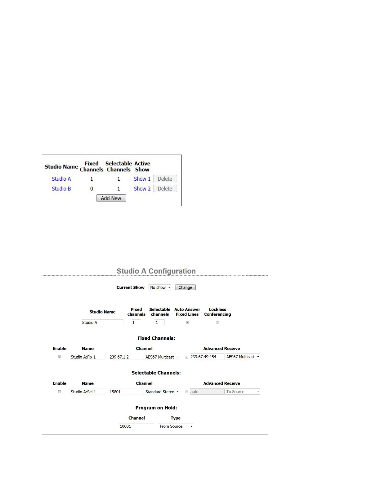
INSTALLATION AND CONFIGURATION
♦ RFC 2671 MD5 digest authentication is supported.
♦ RFC 2833 DTMFs must be supported.
♦ Supports SRV address lookups.
♦ Has basic NAT support
♦ Unlike some other SIP devices, the VX supports non-numeric “extensions”. This is sometimes used by hosted PBX
services.
CHAPTER 2
Studios Menu
The Studios page lists all of the Studios that you have configured
for your system. It lets you add new ones. And it lists the Shows
that studios are using. A Studio is a collection of controllers,
GPIO, and audio I/O while a Show is a collection of lines to be
used in the studio.
Individual Studio Conguration Pages
| 29
The individual Studio pages are to configure each studio. For each, you can choose how many console faders you want to devote
to selectable and fixed lines and you assign the Livewire channel numbers to each. First the Studio Configuration cannot be
edited while it’s in use, so notice how the CURRENT SHOW is set to NO SHOW. This is required in order to change the studio’s
configuration.
Page 39

INSTALLATION AND CONFIGURATION
STUDIO NAME allows you to name the studio. This is the name that will show up in the lists available in the VSets, Consoles
and VX show profiles.
AUTO ANSWER FIXED LINES enables auto answer for fixed lines in the studio. When this is enabled, fixed lines will be
automagically placed on its corresponding hybrid after the first ring. Because end-of-call messaging occurs when the caller
hangs up and the VX responds accordingly to these signals, auto-answered fixed lines can theoretically be completely
unattended. This is extremely useful with IFB and Intercom applications.
LOCKLESS CONFERENCING refers to Selectable lines. Checking this box bypasses the traditional telos “button mashing”
workflow by allowing the user to conference lines without locking them first.
When a number is entered into the FIXED CHANNELS and SELECTABLE CHANNELS fields (and click apply), you’ll see a
set of fields appear to configure these channels. Whenever we say the word “hybrid,” one of these FIXED or SELECTABLE
CHANNELS is what we are talking about. Enter the name you would like to use for the hybrid in the NAME field. The
CHANNEL field is where the Livewire channel number or the AES67 multicast address is entered. The drop-down box allows
you to specify between Livewire Live Stereo, Livewire Standard Stereo, or AES67 Multicast streams. The ENABLE checkbox
activates or deactivates the hybrid.
ADVANCED RECIEVE activates a field where you can enter a Livewire channel number or AES67 multicast IP address for
audio being sent back to the caller. This is for setting up a manual mix-minus or backfeed to the caller. In a typical Axia
environment, the console engine will automatically create and send the VX backfeed audio (to the caller) to the VX engine
using the same channel as the VX source (from the caller). In this case, the Advanced Receive checkbox remains unchecked.
However, if you want to connect the VX to another brand console via an xNode, check the box. “From source” should be
selected at the dropdown box and enter the LW channel number of the desired xNode source. This is the audio that goes
back to the caller, it should be a Mix-Minus or “clean feed” (in other words, the caller’s audio is not being sent back to the
caller via the VX).
CHAPTER 2
| 30
Note that when you assign Livewire channels to outputs, Livewire streams will start to flow on the LAN network port. Livewire
streams system and network consume resources as soon as they are defined with a type and channel number.
It is suggested that you assign Livewire channel numbers according to App-note “Livewire Channel
numbering. Livewire channels must be unique and should not start with “1, 2, 3...”. Channel
numbering is completely exible, but we recommend to always use the last byte of the device’s IP
address as the rst 3 digits of that device’s output stream numbers. For example, if our VX’s IP
address is 192.168.2.200, the rst channel in the rst studio will be 20001. This way, you can always
be sure what the IP address of the device is that is creating a stream on a specic channel number.
Remember that in a Livewire environment, Livewire channels carry audio in two directions, so both send and receive are
covered at once. ‘Live Stereo’ should usually be chosen as the Mode to keep the delay as low as possible. Standard stereo or
mono can be used for Program on Hold or IFB feeds where a few extra ms of delay is inconsequential.
PROGRAM ON HOLD is the audio a caller will hear when placed on hold from the VX in this studio. Since only one of the two
Livewire audio directions is needed, you can choose which is appropriate for your studio set-up. From Source is the usual. In
most situations, the program on hold is the feed from the consoles main program buss.
You must congure a Program on Hold feed for each studio. It could be a generic program or air feed
but if no working channel is assigned calls on hold may drop after 30-60 seconds. This is due to the
fact that some PBXs, Trunks, and some endpoints will hear silence and will disconnect thinking the
call was lost. It’s also a “best practice” to feed Program on Hold feeds “Pre-Delay” to minimize
confusion for those on hold.
Page 40
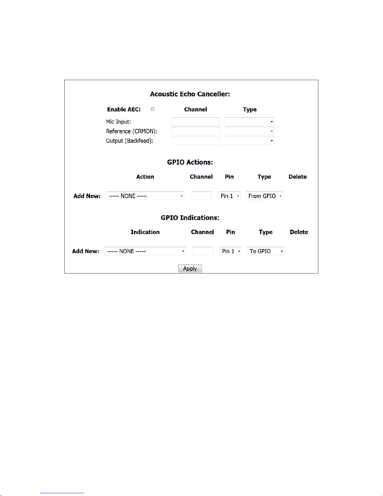
INSTALLATION AND CONFIGURATION
CHAPTER 2
| 31
Acoustic Echo Canceller
Each studio has an ACOUSTIC ECHO CANCELLER available. The two inputs and the output are assigned to Livewire channels
on this page. The output of the AEC is labeled Backfeed because the output of the AEC is what you usually would feed back to
phones. For configuration purposes, you can think of the AEC as a separate functional block outside of other VX functions.
There is no internal connection from/to the AEC and other VX signal paths.
The Acoustic Echo Canceler helps with the problems that occur when you need to have loudspeaker monitoring of calls in the
same room as the microphone feeding the phone. Without a canceler, the received caller audio would be returned to the caller
as an annoying echo. (In the old days, this acoustic coupling would probably cause feedback howl instead of echo, but today’s
mobile phone and VoIP delays have made echo the trouble du jour. The canceler needs two inputs and produces one output. The
MIC INPUT (From Source) is fed from the studio microphone. This can also be the entire Mix Minus signal. The REFERENCE
(CRMON) (From Source) input is the audio that needs to be cancelled. This is audio that is going to the monitor or preview
loudspeaker. The OUTPUT (To Source) of the canceler goes to the VX phone feed input(s). Lastly, the ENABLE AEC checkbox
does exactly what you would think it does.
Why didn’t we just internally connect the canceler? Because the canceller works best when the reference input is after anything
that is in the phone-to-speaker path, such as the volume control and mute. In a Livewire-equipped studio, it should not be too
difficult to tap the needed signals. The canceler is low-distortion and full-fidelity, so it may be used with wideband codecs.
Page 41

INSTALLATION AND CONFIGURATION
CHAPTER 2
| 32
GPIO
VX supports GPIO (General Purpose Input/Output) control. It’s a useful way to control functions in the VX or to get helpful
indications of VX conditions or modes. The Livewire channel assignment for this is done on this page.
Electrical connections are made via Livewire GPIO xNodes. They are equipped with D connectors using the Axia standard 5
inputs and 5 outputs per channel. You’ll find more about these in the appendix of this manual. The configuration starts with
zero GPIO channels, and you add them as you see fit by selecting a function from the ADD NEW drop-down menu. There are
separate ACTIONS (inputs) and INDICATIONS (outputs) to choose from in these menus.
For ACTIONS, enter the Livewire Channel number of the GPIO port being used for the outputs in the CHANNEL field. Then
select which PIN the function will correspond to. Finally, since Actions are inputs, select FROM GPIO for TYPE. Available
actions include: TAKE NEXT CALL, BLOCK ALL, AUTOANSWER AND HOLD, MUTE RINGER, among others.
For INDICATIONS, enter an available Livewire Channel number in the CHANNEL field (or the appropriate channel number
for the GPIO port you are using). Then tell the VX on which PIN the output will appear. Since Indications are outputs, set
the TYPE to TO GPIO. Available indications include: LINE RINGING, NEXT CALL AVAILABLE, BLOCK ALL ACTIVE, RINGER
MUTED, AUTO HOLD AND AUTO ANSWER ENABLED, among others.
Since each GPIO port has 5 input and 5 output pins, you can have up to 5 indications and 5 actions on a
single LW channel number / GPIO port. Also note that GPIO Livewire channels are not advertised to the
network. Therefore, you will never see GPIO Livewire channels in the BROWSE window of the xNode.
GPIO Actions are inputs to the VX from some external source, which could be nothing more than a pushbutton. GPIO
Indications are outputs from the VX. For example, “there’s a Ringing Line” could be used for a wall-mounted lamp and Delay
dump was pressed to trigger a profanity delay unit. You can find the details regarding the corresponding pins of the GPIO
connectors in the various GPIO xNode manuals or in the “GPIO Reference” in the appendix of this Manual.
Address Book
Users of the VSet telephones will likely want to have pre-configured phone numbers stored for dialing. When a studio is
selected from the CONFIGURATION > STUDIOS page, an ADDRESS BOOK link will show in the navigation bar to the left.
Click on it and you will be taken to the Address Book for that particular studio. Configuring it is simple. Enter the name of the
contact in the NAME field and enter the phone number / SIP address of the contact you would like to store. Click ADD to save
the entry. These items are viewable in the VSet’s ADDRESS BOOK menu.
Page 42
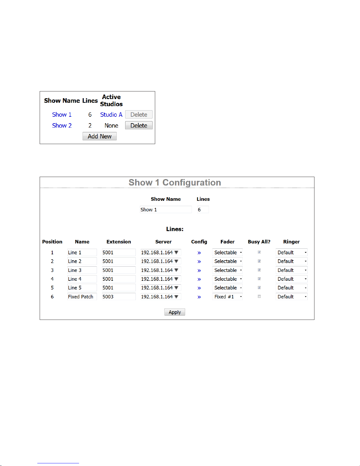
INSTALLATION AND CONFIGURATION
Show Conguration
In the VX, a Show is a collection of lines that are available for a Studio. A
Studio can log out of one Show and log into another bringing up a
completely different (or the exact same) set of lines on the VSets and
other controllers. In the main Shows page, you will see a list of shows
that are configured and the Studios they are currently assigned to. In
order to edit or delete a Show, it must not have any studios logged into it.
To enter a Show profile, click a Show name.
Individual Show Conguration Pages
CHAPTER 2
| 33
In the above example, we’ve logged Show 1 out of Studio A so that we can edit the configuration. When a show is in use, you’ll
see the Studio listed at the top of the page. To log the studio out of the show, we click the blue link at the top, which will take us
to the Studio’s configuration profile. From there, we can select NO SHOW for the CURRENT SHOW and click CHANGE. Then
we can go back to the Show profile and edit away. The name of the Show can be edited as can the number of line positions
available.
With the individual Show x configuration pages, you tell the system how to assign Telco lines to VSets and other controllers.
You give each line a text Name that appears on controllers. The Extension and Server fields reference the SIP server and the
extension configured earlier. With the Fader selection, you decide if the line is to be Selectable (a number of lines switched
into a single or a few faders) or Fixed (one-to-one correspondence from lines to faders). The order of the fixed lines in the
drop-down menu correspond to the Fixed channels configured in the Studio profile. You specify if a line is to be affected by the
Block/Busy All function. Finally, the Default Ringer for each line can be selected if you have uploaded custom Ringtones to the
VX system. We’ll talk about this a bit later.
Page 43
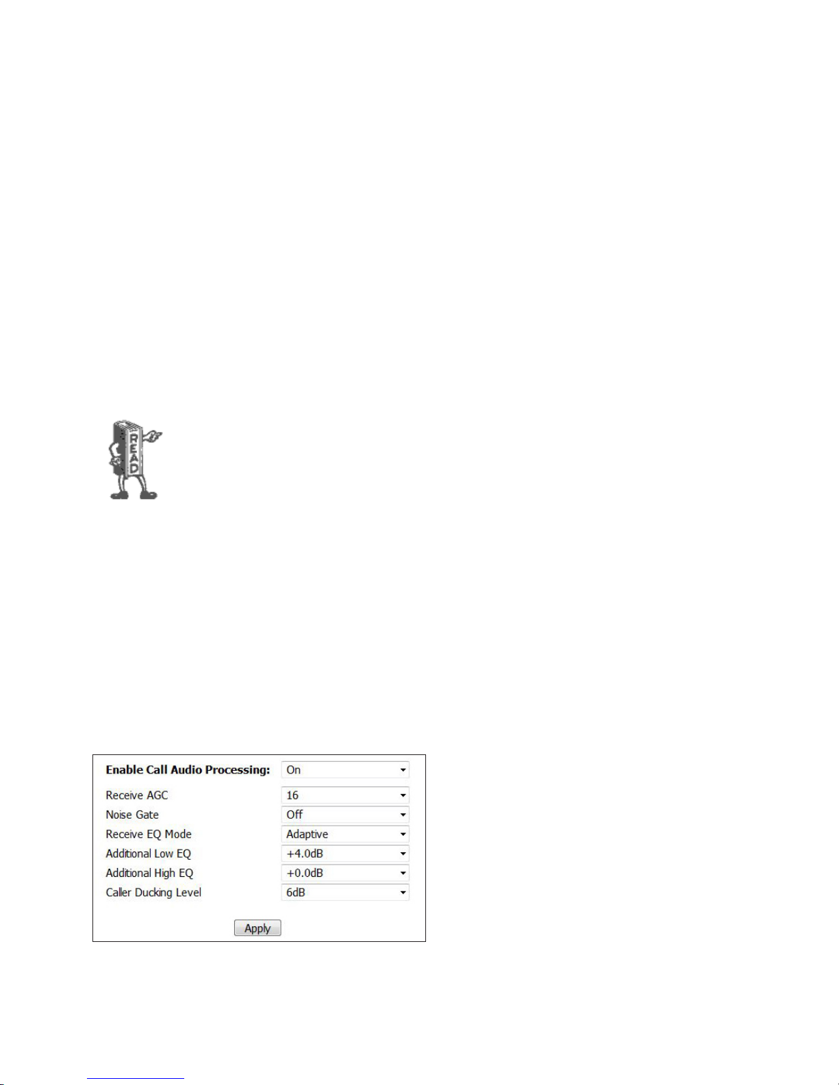
INSTALLATION AND CONFIGURATION
The SIP EXTENSION is like an extension number in a PBX system, with the difference that it is generally not required to be a
number, though most often it is. It maps incoming calls to the line positions on the controllers. Together with SERVER it makes
the SIP URI (address) identifying the line. The server is also used to form SIP addresses from numbers for outgoing calls.
You can assign the same extension to multiple buttons as we have done here. Calls will ring in on the first available button,
acting like a hunt group.
CHAPTER 2
| 34
Address Book
There is yet another Address Book menu for each show, just in case. This one works exactly the same as the address book in
the studio profile. The VSets will display the sum of all the entries across the studio and show it’s logged into. This is so that
you can store commonly used station business numbers in the studio profile and show dependent “expert callers” in the show
profile. We told you the VX was flexible!
Using the VX to replace ‘Couplers’
If your station uses “Pre-delay IFB (Interruptible Fold-Back) Couplers or “listen lines”, the VX can
replace an entire wall of hardware, and by using DID (Direct Inward Dial) numbers instead of POTS
lines, you can also save a lot of money each month by replacing those expensive analog lines.
Create dummy studios for each coupler bank and shows with the phone number or extension you
want to use and tick the auto-answer box next to it. Choose the audio feed from among the Livewire
sources.
Full details are in the “Using VX for couplers” and “Creating ‘Dummy’ Studios” for call screening and
couplers App-note toward the back of this manual.
Call Audio Processing Page
The VX has dynamics processing on both the send (from studio, to caller) and receive (caller) audio directions.
The send (to the caller) audio processing is fixed and consists of a protection limiter and some EQ. The purpose of the limiter
is to protect the Telco line from the distortion that would result from clipping due to an audio overload. Livewire studio audio
has a much larger dynamic range than telephone lines. We use a limiter rather than an AGC because we don’t want the system
to increase low-level signals, which could cause feedback and sound unnatural to the caller. These features do not have any
controls to show in the menu set, we’d just thought you’d like to know what’s happening under the hood.
The receive processing includes ducking level, an AGC,
noise gate, and dynamic EQ.
The term “hybrid” is used only for convenience here,
since VOIP is inherently four-wire (separate transmit
and receive). The only echo possible is each from the far
end which is either acoustic or reflected at a four-wire to
two-wire (POTS) hybrid, found in Telco line equipment
connected to bad (usually very long) subscriber loops.
Receive AGC. Automatic Gain Correction (AGC) control
is available for the caller’s audio. The purpose of the AGC
is to ensure that each caller sounds similar to the last,
no matter what kind of call it is (Cellular, VoIP, Legacy Connections, etc.) Another plus to having AGC present is it adds
to the production value since no “fader riding” is necessary. The AGC does it for you. We recommend setting this to “16”
(maximum)
Page 44
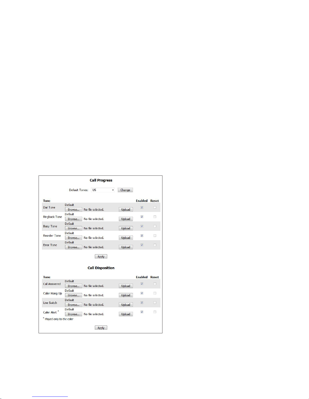
INSTALLATION AND CONFIGURATION
Noise Gate. This feature will attempt to remove background caller noise by gating (turning off) the output when the audio
drops below a certain threshold. We recommend leaving this setting off because it could mistake a soft-spoken caller for noise
and will gate unexpectedly. If callers commonly call in from noisy environments, you can play with this option to see if the
quality improves.
Receive EQ Mode and Additional EQ Settings. The mode dictates the function of the receive EQ algorithm. Setting this to
OFF bypasses all equalization of the caller’s voice. Setting the Mode to Fixed will tell the VX to only apply the equalization
specified in the Additional High and Low EQ fields. In Adaptive mode, the VX will automatically set the EQ levels of callers
in an attempt to make all the callers sound similar, no matter what type of call it is. (Cellular, VoIP, Legacy Connections, etc.)
High and Low EQ can be added to this automatic EQ by specifying a value in the fields. We recommend using 0dB for High and
+4dB for Low
Caller Ducking Level. The purpose of this is to provide an effect that many DJs and talk show hosts prefer – that the caller
level is reduced when they speak. The ducking function reduces the gain in either the send or receive path depending on who
is talking at a given moment. There is a smoothing filter with time-constants tuned to make the effect as natural as possible.
The amount of ducking is a user-adjusted variable value and may be defeated entirely if you choose. 6dB or 12dB are the most
popular settings.
CHAPTER 2
| 35
Assigning Sounds & Tones – The Tones page
SIP signaling is via digital message, not by tones in the
audio like it used to be. This means the VX has to make
its own sounds in response to various line status
conditions for human consumption. We provide default
sounds, which are the traditional tones generated by the
PSTN, but you can upload your own to create a unique
on-air ‘signature.’ Once in the main Tones page, you’ll
find DTMF and RINGTONES menus listed under the
Tones menu in the navigation bar.
You can also use any sound you like to signal that a new
call has been taken. This is actually a cool new feature
made possible by modern technology. Rather than a new
call appearing silently, the event can be accompanied by
a signature sound.
Years ago, we installed a fancy new Telos system
at Z-100, New York, replacing an old key phone
setup. The new system had a mute function to
remove the loud and annoying ‘clunk’ that banged
out when each call was taken to air. On the rst
day, star morning DJ Scott Shannon called Frank
Foti, the Chief Engineer, to complain he was missing his “kerchunk kerchunk”. He liked the clunk,
saying it created a kind of dramatic “yer-outtahere” punctuation when he dismissed a call and
took another. He would have loved this feature of
the VX. We’ve included a key phone button punch
sound in his memory.
For line status (sometimes ‘called ‘call progress’ tones), the Tones configuration page lets you choose either USA or Euro
standard for the default tones. You can upload your own sound also. Files to be uploaded must be mono, in the signed *.au file
format, linear PCM (8, 16, 24 or 32bits) or 32-bit normalized floating point. Ringtones MUST be 8kHz, 16-bit, mono, other
tones 48kHz. You can use the free Audacity audio editor to convert whatever you have to this format. Use the Export command
and choose the required values.
Page 45

INSTALLATION AND CONFIGURATION
The files you wish to upload must be available on the PC that hosts the Web browser you are using to access the VX. Your tones
can be any length, but should normally be kept short to conserve memory (and to avoid annoying listeners…). You do have
the option to revert back to the default tones if you later decide to go with the default sounds.
CHAPTER 2
| 36
Call Progress Tones:
Dial tone. This is only heard when a line button is pressed before a call is dialed.
Ringback tone. Heard when dialing is completed and the called phone is ringing.
Busy Tone. Heard when the called phone is busy.
Reorder tone. (fast busy) Signals that there are no call paths available in the PSTN, usually caused by congestion in links
between central offices. In the USA, this is is the ‘fast busy’ - a dual-frequency tone of 480Hz and 620 Hz at a cadence of 0.25s
on/0.25s off.
Error Tone. Usually caused by an incorrectly entered number, but can be from other problems in call setup.
Call Disposition Tones:
Call answered (Sound effect). Played whenever a call is put on air (whether directly, from handset or from hold).
Caller hang up (Sound effect). A brief “bump” sound that is heard when an on-air caller disconnects. We recommend that you
leave this enabled because call disconnect is completely silent when using SIP and the host might not realize that they’ve been
disconnected. While the sound isn’t loud or obnoxious, hosts pick up on it while listeners don’t seem to notice it.
Line switch (Sound effect). The sound that is heard on the air when there is a call on-air, and a new call is taken to air by
pressing a line-select button. This is the one Scott Shannon wanted. You can always insert your own or uncheck the Enable
checkbox to disable it.
Caller Alert tone. Sent to caller when call is answered, or when caller is taken to air from hold, to inform the caller that they are
now on-air. The Caller Alert sound is sent to the caller only and is not played on the air.
The Caller Alert tone’s purpose is to let a waiting caller know that it is his turn to talk. Since he has
usually been listening on hold, he will have heard the host say “hello, you’re on the air” a few times
before it really is his turn. Since this sound is played only to callers being switched to air, it clears the
confusion. By default, it’s a tone that VX users instantly recognize. If you liked the older noise bursts
that were actually necessary in the older Telos systems and would really like your VX sound like a
2101 or original Telos 10, contact Telos Support and we can send you the les to do this.
On Air DTMF Conguration
Choose the DTMF menu to set these tones. Dialing key presses send call setup messages digitally to VoIP lines or gateways.
Though they are not sent to the Telco line, standard DTMF (Dual Tone Multifrequency) tones are played on-air - but they are
scrambled so that listeners are not able to easily detect the number being dialed. The correct DTMF tones are played to the VSet
handset and loudspeaker. If you wish to upload your own tones, they must be in the *.au file format, 48Khz linear PCM.
Ringtone Conguration
Ringtones play through the Vset speaker when a line is ringing. (if not muted via GPIO or VSet settings) The recordings
uploaded to this page must be in the *.au format, 8Khz linear PCM. Ringtones can be assigned to specific VSet line positions in
the Show profile. Ringtones with higher numbers take precedence. For example, if one line has ringtone #1 assigned to it,
and another line has ringtone #5, and both lines are ringing, the Vset will play ringtone #5. The Ringtones are assigned in
the Show Profile.
Page 46
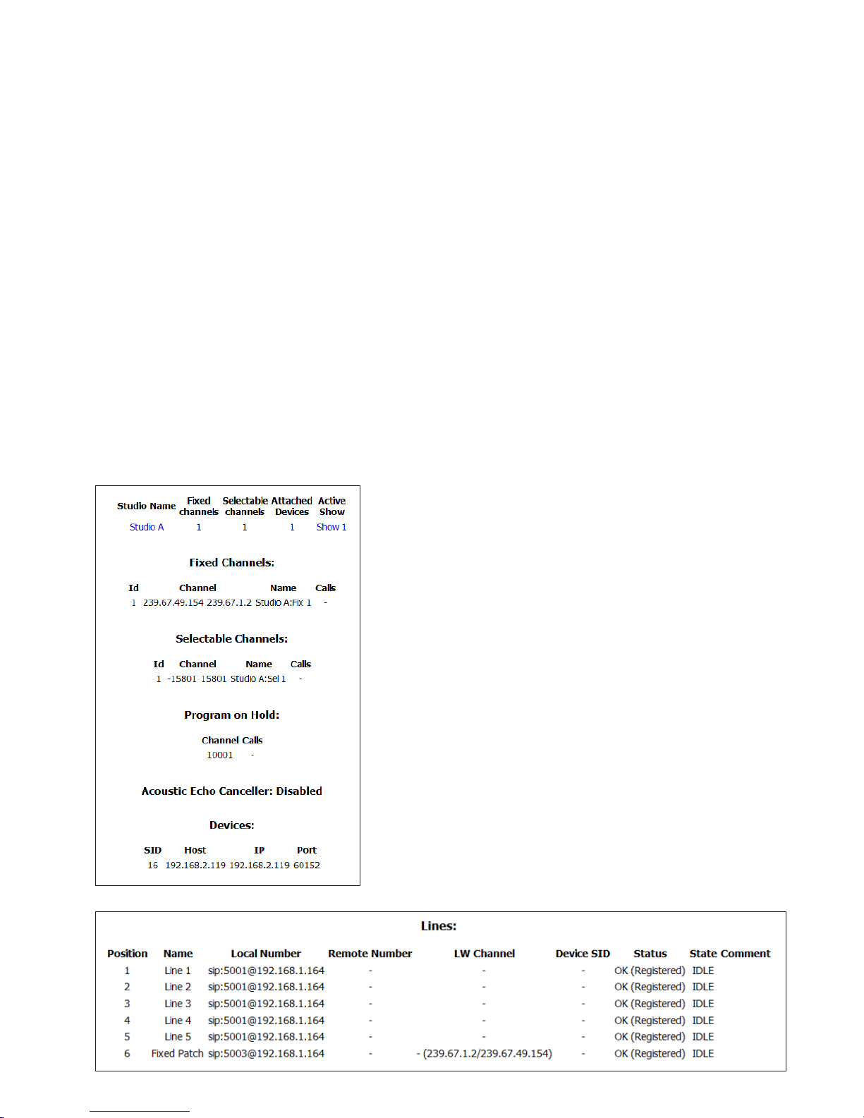
INSTALLATION AND CONFIGURATION
CHAPTER 2
| 37
SIP and DTMF
The VX uses standard SIP techniques for dialing. A SIP call setup message containing the number is sent to the IP network. The
gateway to the PSTN generates the DTMF (Dual Tone Multi-Frequency) audio signal that the PSTN uses to direct the call.
The VX generates DTMF audio just as sound effects really. Listeners expect phones to sound like phones. DTMF tones “played”
for the audience are not the actual digits dialed and some are not even “real” DTMF digits, but sound like them. This is so that
if a number is dialed “live, on the air” nobody can get the telephone number being dialed by recording the program audio or
“decoding” the tones heard on the air.
There is sometimes the need to send DTMF to the PSTN after a call is connected, such as for automated attendant systems or
“dial up” remote control systems. In this case the VX sends a special SIP message that tells the PSTN gateway to generate the
corresponding audio DTMF tones, according to the standard specified in the IETF (Internet Engineering task force) RFC2833.
Information Pages
These pages provide some insight to the inner-workings of the VX for troubleshooting and management purposes.
Studios Information Menu and Pages
The studio Information Menu provides a list of Studios, Fixed and
Selectable Channels handled by that Studio, devices (VSets and other
controllers) connected to the Studio and the Show that is logged into the
Studio. Clicking on a Studio Name will take you to the Information page
for the studio.
The Studio’s information page will repeat the details provided by the
Studio Information list and provides more information about the Fixed
and/or Selectable channels, POH, the IP address of the Devices connected
how many calls are currently active or on hold, and the status of the Line
positions. This is really helpful if you are having trouble with lines on the
VSet. You can also navigate to the Studio or Show configuration from here
by clicking the blue links at the top of the information page.
The status of the lines in Studio A (Show 1) say, “OK (Registered)”
meaning they are successfully registered to the SIP server and are ready to
make or take calls.
Page 47
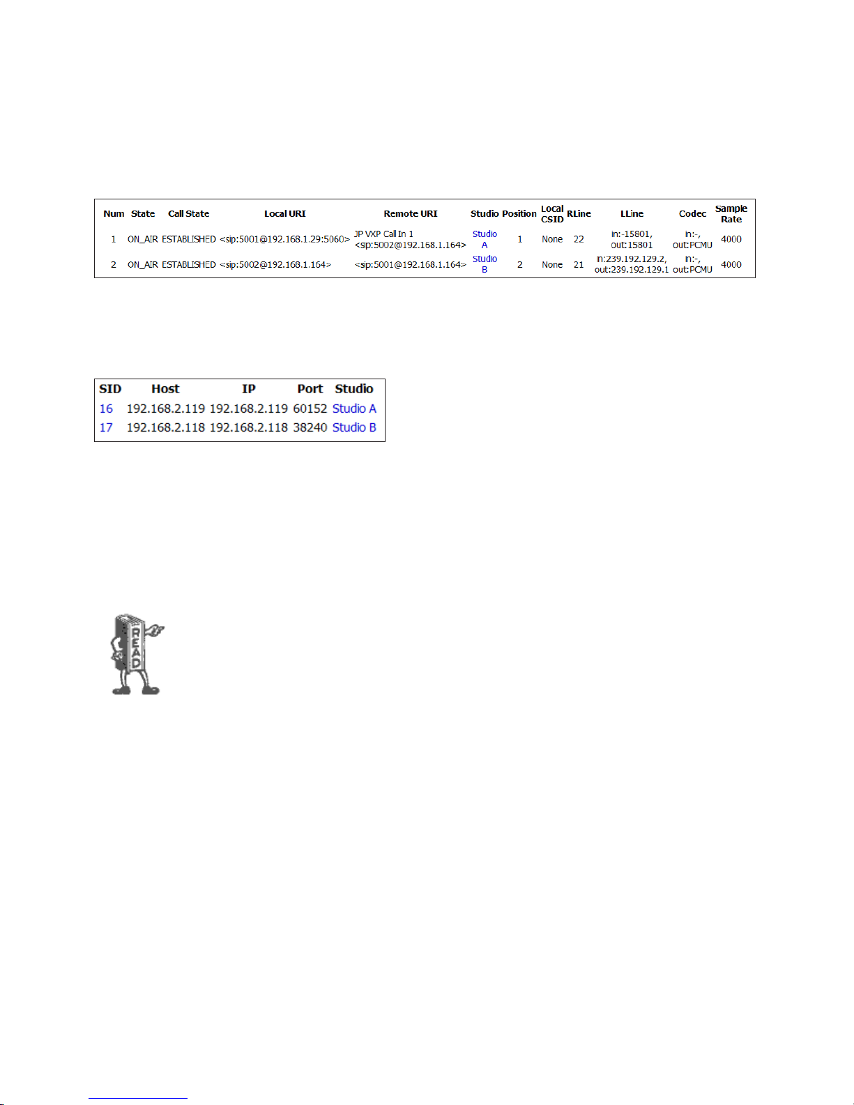
INSTALLATION AND CONFIGURATION
CHAPTER 2
| 38
Calls Information Page
This page informs us of the calls that are currently active. The information provided includes local and remote URIs, which
studio has the call active, what line position on the Studio’s VSet the call is on, what codec it’s using, etc.
Devices Information Page
The Devices page shows us what devices (VSet’s, Consoles, PCs, and
other controllers) are currently connected to the VSet. In our
example, Studio A and B have one VSet apiece. The IP address and
communication ports are listed as well as the studio that owns the
device. Clicking the Studio name on this page will take us to the
Studio Information page listed while clicking the SID will take us to a page listing more information about the device if
available.
Stream Statistics Information Page
This page displays statistics about the streams handled on the LAN port. It provides over and under run, jitter, and other
information that is useful when troubleshooting audio problems.
Audio dropouts, clicks, pops, and other audio annoyances can usually be narrowed down to
problems with the network itself. Most who have done any troubleshooting in a Livewire
environment will be familiar with these statistics. These problems are usually caused by an unstable
clock on the AoIP network or an improperly congured Ethernet switch. In our experience (going all
the way back to our original Telos 10 hybrid), problems with the phone calls are usually narrowed
down to the line itself or the provider of the line. Todays connections with SIP and ISPs are no
dierent. If the VX is booting and operating, there’s probably nothing wrong with the hardware. If
the hardware is OK and the system conguration hasn’t changed, there’s an excellent chance
something changed on the network or with the provider.
System Status Page
This page displays all of the hardware statistics for the VX Engine. You’ll see CPU and memory allocation data as well as system
health and software version information. Don’t be surprised if Telos Support asks for a screenshot of this page when asked to
help with an issue. You can also reboot the VX chassis from this page using the button at the top.
Licenses Page
System Licenses are available to unlock additional features such as more available channels for faders (VX Enterprise only)
This page allows you to enter your new license number as well as backup your current licenses. It will also tell you how close to
the fader limit the VX is.
Page 48
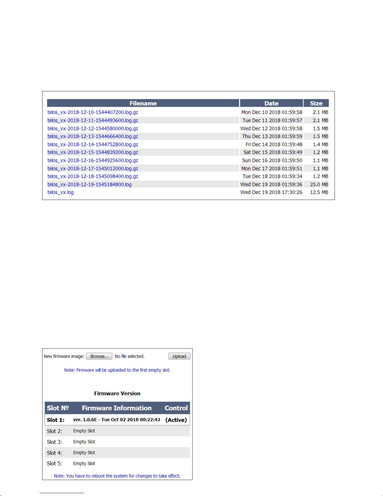
INSTALLATION AND CONFIGURATION
CHAPTER 2
| 39
System Logs Page
The VX’s logging capability is a powerful tool to track down problems –even those due to operator error – we do recognize that
operator error is rare and nearly non-existent.
The logger in the VX Enterprise and VX Prime+ is different from the older hardware platforms in that the logs are no longer
stored in only in RAM, it writes it to internal storage and saves them there. This solves two problems. Since the log goes to
internal storage and not just RAM, log entries aren’t lost when the system needs to reboot because of a crash and it no longer
necessitates the need for an external syslog logger. Each log is archived once per day and given a name with the date. The date
and time is also listed next to the file link along with the size of the log file. To view the current log, download and view the file
called “telos_vx.log” with no date and time listed.
While you might be able to understand the log messages after some effort, we don’t expect you to do so. These are mostly
intended for our support people, who would advise you as what settings to use for the capture and then interpret the result.
These are simple text files and if you look through them you may find something interesting or useful for troubleshooting.
Internet standard Network Time Protocol (NTP) is used to provide an accurate timestamp to the events captured in logs. For
accurate timestamps, you need to have an NTP server accessible on your network and its IP address properly configured on the
System page.
Firmware Update Page
New firmware for the VX Engine is first obtained from Telos
via email, Internet download, etc. It is then uploaded to the
VX Engine using this page.
You can have as many as five stored in the Engine at one
time. On this page, you choose which of them will be active.
Reboot the Engine after activating new firmware.
When more than one version is listed, you have the option to
activate or delete the version. Note that the currently active
version is the version that is currently running, so you can’t
activate or delete it.
Page 49
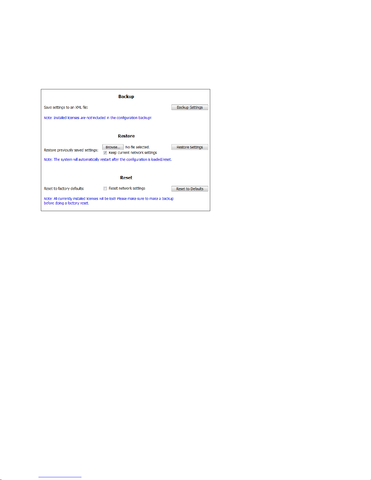
INSTALLATION AND CONFIGURATION
Backing up and Restoring Engine Conguration
Click Backup Settings to download a backup
configuration file. The backup file for
configuration settings is stored on your local
machine or on a removable drive attached to it.
To load a backup configuration, click the Browse
button under the Restore section and navigate to
the backup file on your computer. When a file is
selected, click Restore Settings to execute.
When restoring, either from backup or to factory
defaults, it is possible to keep the current network
settings intact. Note that VX will automatically
restart to apply the new configuration.
DO NOT attempt to load a backup configuration
from another type of VX system. For example,
you can not load an older VX or VX Prime
configuration into a VX Enterprise or VX Prime+.
Also, don’t attempt to load a VX Enterprise config into a VX Prime+ engine and vice versa.
CHAPTER 2
| 40
Many people have multiple VX engines, and keep a single one as a spare, with the configs of all of their live systems in a folder
on their computer. This makes it easy to drop a config on a system and make it the “live” unit while you get the other repaired.
The system can also be set back to factory default settings from here.
Notice that the backup configuration will not save licenses. In order to back these up, you’ll need to go to the licenses page and
back them up from there.
Page 50

OPERATION
CHAPTER 3
| 41
3 Operation
VSet Operation
There are full sets of manuals for the VSet series of controllers available on our website. This section is meant to be a quick,
“Schoolhouse Rock” version of the VSet operation. If you would like more information about VSet operation and setup, refer
to the product manual for the controller you have.
Select Studio and Show
If these have not been already selected, this should be done as the first step before using the VSet. Press the Menu button to
access the menu functions. The LCD will show the various items that can be changed. Select the studio and show you want and
then exit the menu by pressing the Menu button.
Installation setup options such as Setup or Engine Setup are protected by requiring that appropriate key is pressed and held
for 5 seconds when configuration options will be changed. Otherwise, they are greyed out. These settings can cause problems if
changed casually or by the wrong people.
Selecting the Studio is done through the Engine Setup menu (press and hold to access) while the show setting can be done by
any user from the Main Menu. The studio option is not expected to be change often or casually, but probably only when a new
VSet is installed or one is replaced.
Set Talent or Producer Mode
The VSet should be set to Talent mode when it is located in the studio and is used to put calls on the air. Producer mode is for a
VSet that is being used by a producer to screen calls. In Producer mode, calls cannot be put on-air and are protected from being
dropped. The function of the right line button column is different in the two modes to serve the needs of each type of operator,
as described below.
Press the menu button to access the menu functions. The LCD will show the various items that can be changed. Select Talent or
Producer and then exit the menu functions by pressing the menu button.
The Line Info Display
Each line has a corresponding portion of the LCD display to the right of the line button that shows status and info about that
line.
Next indicator
The ‘>>’ symbol. Marks the line that will be taken when the Next button is pressed.
Fader number
The small yellow/orange rectangle near the status icon.
Page 51

OPERATION
CHAPTER 3
| 42
Line name
The first text line. This is defined in configuration using the VX Engine’s control center web GUI.
Caller ID
Caller ID will be displayed on incoming calls if it is available. Outgoing calls will show the number dialed. The green arrow to
the left of the text points left for incoming or right for outgoing. Calls that are blocked or that come from lines without caller ID
may display ‘anonymous.’
Caller ID information is sent by the PBX or service provider. In some US markets, calls from the “choke network” (High
volume calling lines) will not provide caller ID information, though most do.
Time
The length of time the call has been ringing-in or on hold.
Action Prompt
(None active in the graphic.) Shows what line will be affected by drop and hold when prompted Drop/Hold is enabled.
Choose the line you want to drop or hold after pressing either of those buttons. This is shown only when more than one is
possible; this step is not needed when only one line is possible, when the line would be dropped or held immediately.
Line Status Icons
Dialing
Shows when you are using the keypad to dial an outgoing call.
Outgoing call in-progress
The icon will be animated with the white highlight moving around when a call is in the process of being connected.
Ringing-in
Page 52
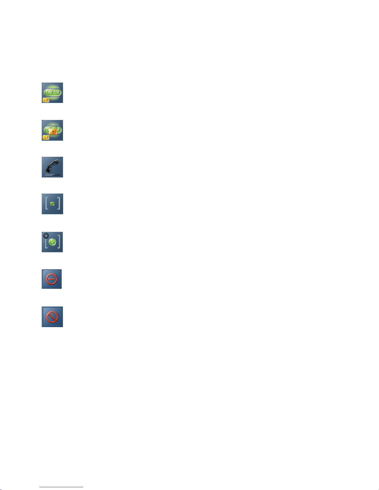
OPERATION
On-air
On-air and locked
On handset
Hold
CHAPTER 3
| 43
Ready Hold (Screened Hold)
Used Elsewhere (in another studio)
Line is blocked
Line Button Columns
Each line has 2 associated buttons to the left of the LCD.
Pressing a left column line button puts a held or ringing caller on the handset.
Press the right column button to put a held or ringing line on air, dropping any other unlocked calls. If a call is already on the air,
pressing the right button locks the line, or if already locked, unlocks it. That is, it toggles between the two states. Not to worry,
we’ve made it difficult to accidentally drop a call.
There is also a “Two-Fader Operation” mode that will make the VSet operate more like the legacy Desktop Director and a 24line option, but we’ll send you to the VSet manuals to find out more about those features.
Call screeners or producers can use the Ready Hold button (the one with the checkmark) to put lines in ready hold mode
and assign priority for the Next function. See “Next” Button and function. Ready hold works like normal hold, except the
line status icon has the checkmark to indicate to operators that a call has been determined to be ready for air, normally by a
producer/screener. The Vset must be in Producer mode in order to use this key.
Page 53

OPERATION
CHAPTER 3
Tip: You can re-order the next priority queue at any time. Put lines in Ready Hold - even those already
on Ready Hold - in reverse order from the order you wish to air them. First, Screen hold the call to be
aired last, then the call to be aired second to last and so on. You would screen hold the call that you
want to be aired next, last. At rst blush, this may seem confusing, but it makes sense when you
remember that the call held the longest goes rst to air.
| 44
Hold Button
Holds a call that is ringing, on the handset, or on-air. If more than one line is in this category, there will be a small hold icon near
the status icon on the lines that could be held. Press the line that you want to hold.
Drop button
Drops a call that is active on the handset, or on-air. If more than one line is in this category, there will be a small drop icon near
the status icon on the lines that could be held.
Press the line that you want to drop.
Lock
Normally, taking a call to air causes any others on-air to be dropped. If you need to conference two or more calls, you can use the
lock function.
Press an already on-air line button to lock it. The line status icon will change to display the locked symbol. Pressing the button
again unlocks the line and the lock icon goes away.
Locked calls remain on-air until unlocked and then another call is taken to air or the call is dropped or held.
The Drop and Hold buttons have no effect on a locked line.
Tip: If congured in your system, using xed lines is another option for handling “guest” or “VIP” calls
that need to say on-air while you switch between other callers. With xed lines you’d have a
dedicated console fader for each of these calls, so you can control volume, and switch them
independently in and out of the conversation, etc.
Page 54

OPERATION
Next Button and Function
The Talent next priority is:
♦ longest waiting ready hold
♦ longest waiting hold
♦ longest ringing-in
The producer can manually override these and assign priority as desired.
The producer mode next priority is:
♦ longest ringing-in
In producer mode, Next logically does not take any held lines.
Block All
CHAPTER 3
| 45
Pressing this button will cause all inactive lines to be dropped and blocked from accepting any calls. Calls that are ringing, onair, on the handset, on hold and the fixed lines will not be affected. The usual application for this function is to let you prevent
early callers from getting in on contests until after you’ve made the announcement and released the lines to accept calls.
When block all mode is selected, as lines become available (they stop ringing or drop off) they will automatically “go busy”.
Pressing Block All again will release the lines and allow incoming calls. Please be aware that this feature will not work with
POTS lines delivered via hardware gateways, though it may appear to work. Callers will hear “ringing” rather than a busy tone.
Numeric Keypad and GO Button
For dialing out, either on the handset or on-air. The keypad works during an active call to generate tones for voice mail and
other services.
While a number is being composed, the digits will appear in the line info field. After a number is entered, the GO button
immediately initiates the connection, in similar fashion to a mobile phone, or, if a us caller dials the number it will
automatically send the call after 3 seconds. This behavior is settable or defeatable in “User Preferences”.
Re-dial Function
After selecting a line, press the GO button before any digits are dialed. The last dialed number appears in the line info field.
Pressing GO again causes dialing to start.
Fader Assign
Normally, when a call is taken, it goes to fader 1, but you can assign it to any of up to six configured console faders. (The
number of possible faders depends upon your specific installation and configuration.) When a call is on-air, or before it is
taken, the round fader assign buttons to the right of the LCD can be used to move the call to the desired fader. The number in
the yellow rectangle in the line info field shows you which fader is or will be used. See the VSet manual for information about
“Two Fader Operation” modes.
Page 55

OPERATION
CHAPTER 3
| 46
Firmware Upgrades
You can upgrade firmware for your VSet by using a web browser and downloading the firmware from Telos. Support may give
you a link in email, or you can find the latest versions at the Telos website. After downloading the firmware image, point your
web browser to the IP address of the VSet that you wish to upgrade (username is “user” and there is no default password, so
leave it blank). Then, browse to the firmware image location on your PC (desktop or downloads folder is common) and select
Upload. To activate the new firmware, select it in the browser and the VSet will reboot. When it restarts, it will be running the
firmware version that you selected. For more information, see the appropriate section of the VSet’s product manual.
Take it Easy
We’ve built a lot of flexibility into the VX system to support all the sophisticated things you might want to do. But you don’t
have to use all the fancy-pants stuff when you don’t need it and a simpler subset will do.
In the simplest case, when you are a talent supported by a producer, you could just use the Next and Drop buttons. You press
the Next button to take calls in the sequence determined by your producer and you press the Drop button when you are finished
with your last call and you want to stop taking more.
One step up would have you pressing the right column line buttons to select the calls you want, one at a time. Again, when you
are finished taking calls, you would press Drop. You could use the left column line buttons to talk with callers on the handset.
At the next level, you would use either the lock function or the fixed line capability to conference calls.
Some Common Questions
Question: “Why don’t I hear any audio after pressing a line button in the handset column (left column)?”
Answer: Double-check that the handset cord is plugged into the handset jack (not the headset jack) on the VSet.
Question: “Why can’t I put a call on the air? When I press the right column line key, nothing happens!”
Answer: Put the VSet into “Talent” mode. When the VSet is in “Producer” mode, calls cannot be placed on the air from that
VSet (so as to prevent accidental call drops, or placing the wrong caller on the air).
Wait, there’s more! Go to our website https://www.telosalliance.com/Telos/Telos-VSet and download
the manuals to all of your VSet controllers. There is vital information in each one of them including
more troubleshooting tips that we didn’t mention here. Seriously, go check it out.
Page 56
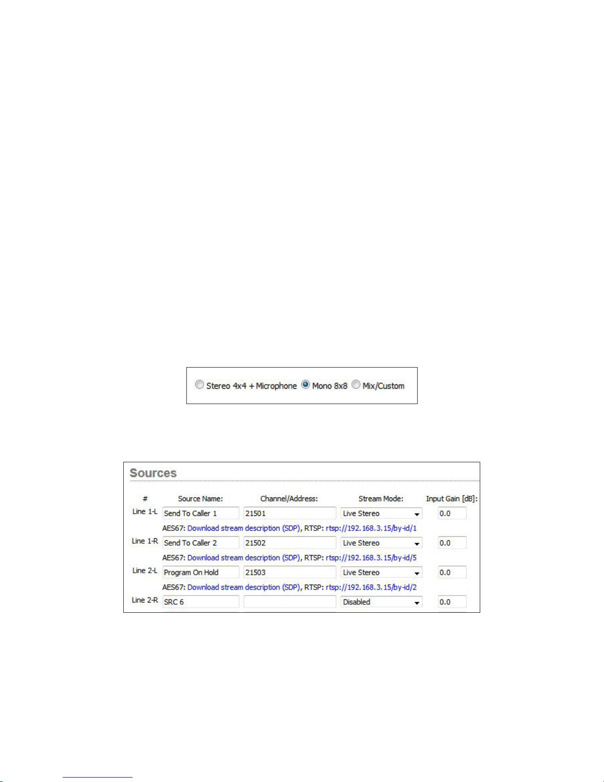
APPENDIX
CHAPTER 4
| 47
4 Appendix
Basic Studio Setup with xNode I/O
In cases where VX is installed into analog or AES/EBU patch-fields, audio xNodes will be needed to get audio into the system as
well as GPIO xNodes for signaling. In this example, we will set up 2 caller faders with 2 separate Mix Minus inputs. We will be
using a Multi-Purpose or Mixed-Signal xNode which contains I/O for Analog, AES/EBU, and GPIO.
First thing to do is to set up the xNode sources. In the xNode’s Simple Setup page, there are three modes: Stereo 4x4, Mono
8x8 and Custom. Because caller channels are mono, we can take advantage of the Mono 8x8 mode.
This adds 4 more source and destination fields that will need to have channel numbers assigned. Go to the SOURCES page
and give each source a unique channel number. (more on this below) In this example, we are setting up one studio with two
faders, two mix minus back-feeds and one program on hold. We will set up three mono source channels:
Page 57
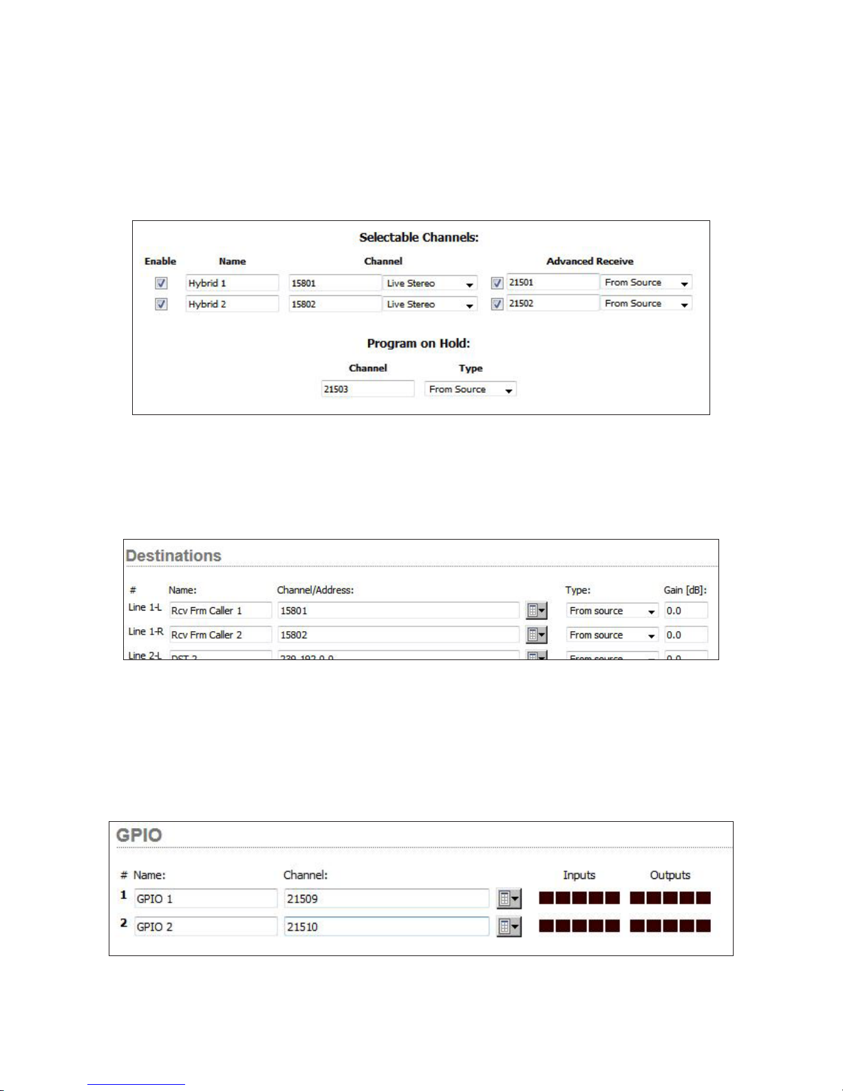
APPENDIX
We’ll come back and set up Destinations in a moment. Next thing to do is set up a studio in VX. See the Studio section of
this manual where we discuss the individual studio configuration pages. For this example, we have Studio A with 2 selectable
channels configured:
In the Selectable Channel section of the VX Studio, there is an ADVANCED RECEIVE column that will need to be activated and
used for this setup. Click the check box under ADVANCED RECEIVE and enter the channel numbers we just assigned to the
xNodes Source (input) page. Finally, Enter the Program on Hold channel in the appropriate field and apply your changes.
Finally, go to the xNode’s DESTINATIONS page and insert the VX Studio’s channel numbers into the appropriate DESTINATION
(output) fields in the xNode config:
CHAPTER 4
| 48
Once these changes are applied, the VX Studio is ready to receive and send audio to callers via the xNode. The sources and
destinations pages tell you which jack the audio will be sent to or received from. In this case, caller I/O is channel 1 L & R and
POH input for the studio is the Left side of input channel 2. This configuration can be repeated / enlarged until the VX will no
longer support any additional channels. xNodes can be added as needed.
If GPIO indications and actions are needed, go to the GPIO xNodes configuration page or the Simple Setup page of the Mixed
Signal xNode and assign the ports available LW channels. Note that GPIO LW channels do not advertise to the network, so you
will not see them in the browse window. In this example, we will continue with the numbering scheme we started earlier:
Page 58
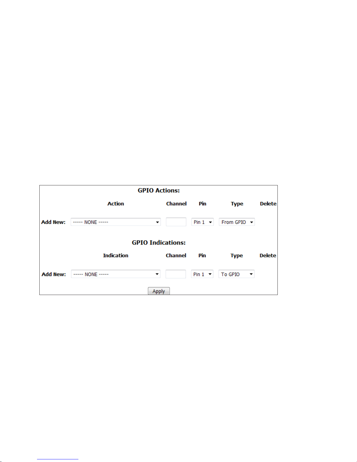
APPENDIX
Finally, return to the VX Studio page and configure the GPIO Actions and Indications as outlined in the Individual Studio
Configuration section of this manual.
CHAPTER 4
| 49
Notes on LW Channel number assignment:
In this example, the IP address of the VX Engine is 192.168.2.158 and the xNode is 192.168.2.215. We have taken the last byte
of the IP addresses and made it the first three digits in the channel numbers used. This does two things for us: 1) It reduces
the chances of accidentally creating duplicate LW channels. 2) It’s easy for us to see which device is which when the channel
number references the IP address like this. Looking at the VX’s Studio configuration page, we can gather the IP address info for
both devices involved. Pretty cool.
Physical GPIO Reference
The GPIO (General Purpose I/O) feature set in the VX Enterprise and VX Prime+ is the most advanced feature set we’ve ever
implemented. It’s totally customizable and you only need to use the features you need. That means no more wasted pins on the
physical GPIO port.
Each Studio has two sections for GPIO. GPIO Actions are inputs to the system to remotely engage a feature or option, while
GPIO Indications are outputs to drive indicators, as the name suggests. We’ve described these fields in the section covering
Studio Profiles, but we’ll repeat them here in slightly more detail. If there are currently no GPIO settings configured, you’ll
only have the Add New fields showing. The Action or Indication drop-down menus allow you to choose what function this
particular GPIO pin will assume. The choices are:
Actions: Take next call, Take next ringing line, Hold all calls, Drop all calls, Enable Block All, Disable Block All, Toggle Block
All, Toggle Auto Answer & Auto Hold, Mute Ringer, Change Shows.
Indications: Next call available, Line Ringing, Line Ringing (Busy All), Line ringing (non-Busy All), Call can be held, Call can
be dropped, Block All enabled, Auto Answer and Hold enabled, Ringer muted, Delay Dump, Current show.
Channel is where a unique Livewire channel number will go. This will be referenced later in the xNode configuration.
Select which Pin the GPIO will happen on. There are 5 input and 5 output pins per GPIO port.
For Type, we are specifying if this is an input (from GPIO) or an output (To GPIO). The default settings are sufficient here.
Page 59
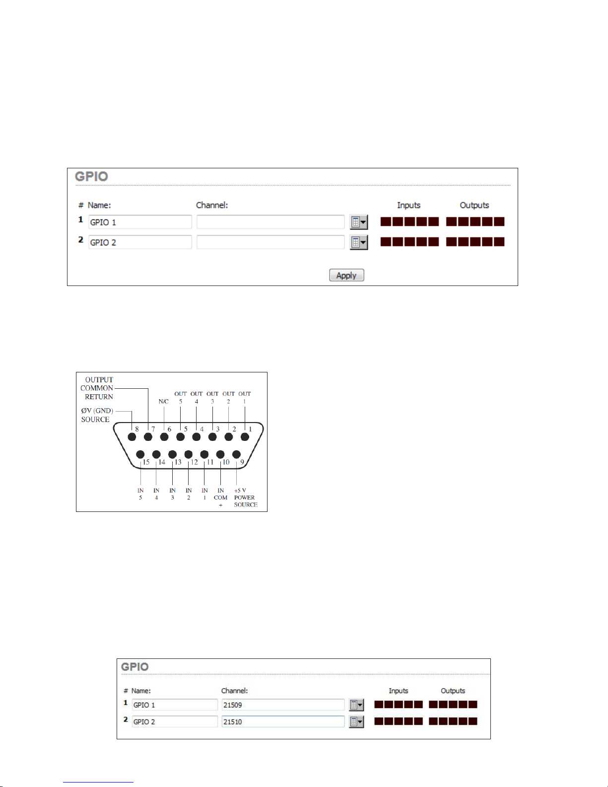
APPENDIX
Once you’ve set up the GPIO section in the Studio Profile, it’s time to configure the GPIO port at the xNode. A GPIO xNode,
Mixed Signal xNode, QoR Engine, PowerStation Main, or PowerStation Aux can be used. The setup is the pretty much the
same in all of these
In the GPIO configuration page, or the GPIO section of the SIMPLE SETUP page in the Mixed Signal xNode’s web user
interface, enter the channel number from the VX’s Studio profile into the Channel field of the desired port. You’ll see a
graphical representation of the status of all 5 input and output pins. After clicking apply, the port is configured.
CHAPTER 4
| 50
GPIO Port Wiring
The wiring of the port can be a little confusing until you realize that
you are in control the normal state of the port. The Output Common
Return and the Input Common pins determine the reference for the
input and output of the port. Therefore, if your device is looking for a
closure to ground at the port’s output pin (normally high), connect
the Output Common Return (pin 7) to the Ground pin (pin 8). At
the same time, if the input pins are to be normally high (device creates
closures to ground), then the port’s inputs need to be referenced to a
voltage. The internal 5V supply can be used for this, simply connect
the +5V pin (pin 9) to the input common (pin 10). This is the most
common use of the port.
Because VX is Livewire, your Axia equipment does not need to have physical ports wired. Most of the hybrid control happens
over the Ethernet network in this case. GPIO channels (also called logic ports in Axia configurations) can be referenced and
you will find more information about this in the product manual for the console / system you have.
Setting up a Mute Ringer GPI
In this example, we will set up a physical GPIO input. This can be applied to all actions and inputs. In this example, we will
configure for a ringer mute input. First order of business is setting up the GPIO port at the node / integrated engine. In this
example, the xNode’s IP address is 192.168.2.215, so the channel number begins with 215xx per our previous numbering
scheme.
Page 60
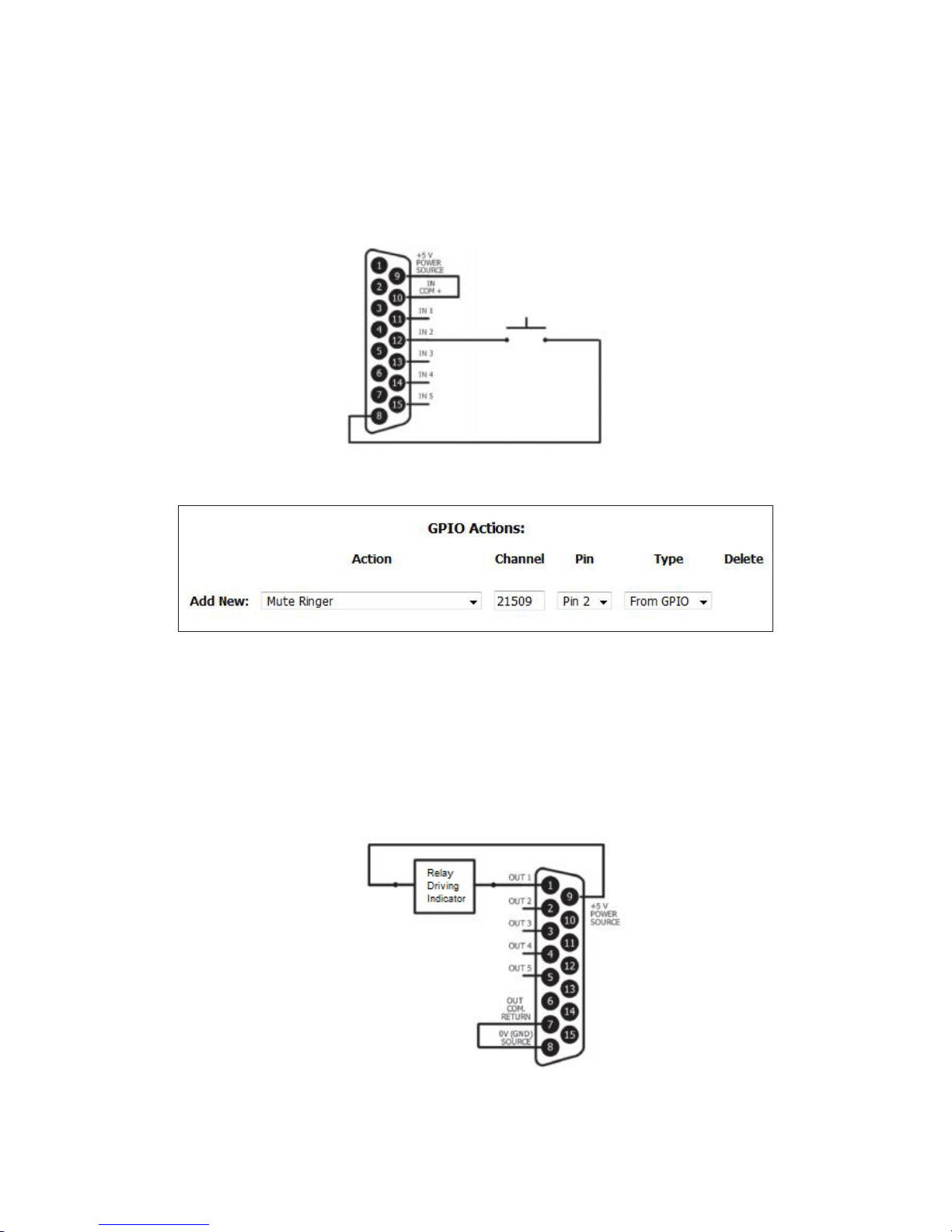
APPENDIX
We will select GPIO port number 1 and will wire the N.O. contacts from a mechanical or solid state relay to it in this manner:
(in this example, we are wiring to input pin #2 which is pin 12 on the connector)
In the Studio page, add a new “Mute Ringer” GPIO action, configuring it for pin 2 on channel number 21509:
CHAPTER 4
| 51
When this is finished and the show reloaded into the studio, a closure at this pin will mute the ringers on the VSets logged into
that studio. This is normally tied to the mic talley.
Setting up a Ringing Indication GPO
This example can be used to configure any indication or output. Just as before, the first order of business is to set up the GPIO
port. We will be using the same port as before (21509), except we will be wiring the coil of a relay (with appropriate fly-back
diode) to output pin #1 this time.
Page 61

APPENDIX
Once the port has been wired, we can assign it to the VX Indications as below:
Once this is complete and the studio is logged back into a show, lines ringing on the VSet will activate this output. In both of
these, notice how the output and input commons are wired.
REMEMBER: LW GPIO channels do not advertise to the network, so you will not see GPIO channels in the Browse window of
destinations fields.
WHY RELAYS? We are specifying the use of relays / opto-isolators because the GPIO port cannot source or sink enough
current to drive an indicator by itself. The xNode manual has more on the current limitations of the GPIO port. If you need to
deviate from these configurations, please consult that text.
You’ll find wiring examples in the GPIO xNode and Mixed Signal xNode chapters of the xNode manual available here: https://
CHAPTER 4
| 52
www.telosalliance.com/Axia/xNodes
The instructions found above will apply to Legacy GPIO Node, Element, PowerStation, and QOR GPIO.
Single Mix Minus Routing with xNode
While all Axia consoles and some other modern manufacturers’ consoles create their own mix minuses for each caller channel,
there are some cases where only a single mix minus can be generated and more than one caller fader is desired. The challenge
now is creating a separate mix minus for each fader so the caller on fader 1 can hear the caller on fader 2 and vice versa.
The xNode has a mixer matrix that can be used to overcome this obstacle. One thing to keep in mind is the internal mixing
instance will use additional sources in the xNode. You’ll see what we mean as we move forward here. The idea is to use a pair of
unused sources in the xNode to provide each separate Mix minus.
We will start with an xNode with its factory defaults loaded.
As before, we will go to the SIMPLE SETUP page and choose
8x8 Mono Mode.
Page 62
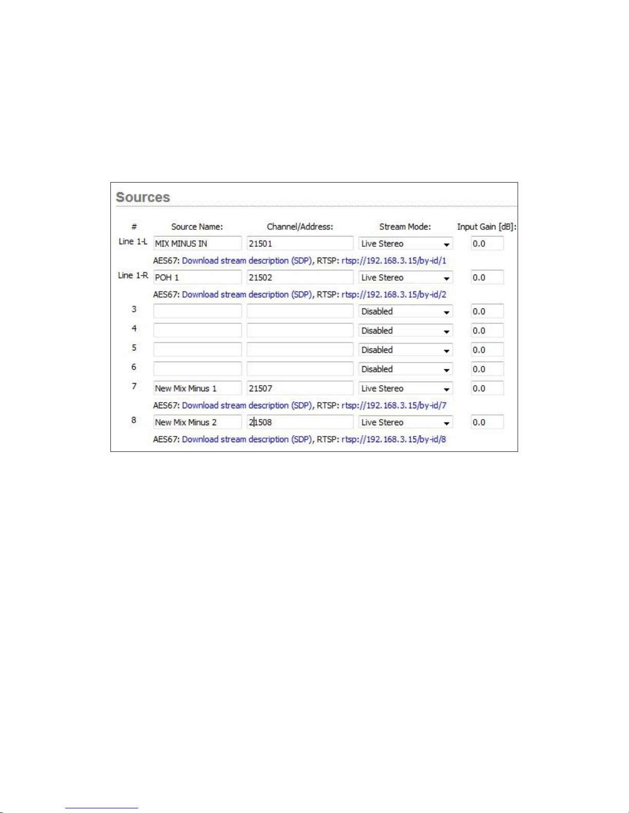
APPENDIX
Then we’ll go to the SOURCES page and set up our Inputs and “New Mix Minus” channels. For this we’ll setup Line 1-L as the
main Mix Minus input and Line 1-R as the Program on Hold input for the studio. Then we will setup SRC 7 and SRC 8 to be our
“New Mix Minus” channels. Notice that we are making these all Live Stereo streams and that the IP address of this xNode is
192.168.2.215, so our channel numbers will begin with 215xx.
CHAPTER 4
| 53
After doing this and clicking apply, we will go over to the MIXER page of the xNode.
The first step in setting this up is to clear the entire matrix. This is done by clicking ENABLE CUSTOM MODE and clicking all
the green boxes and selecting CLEAR.
Page 63
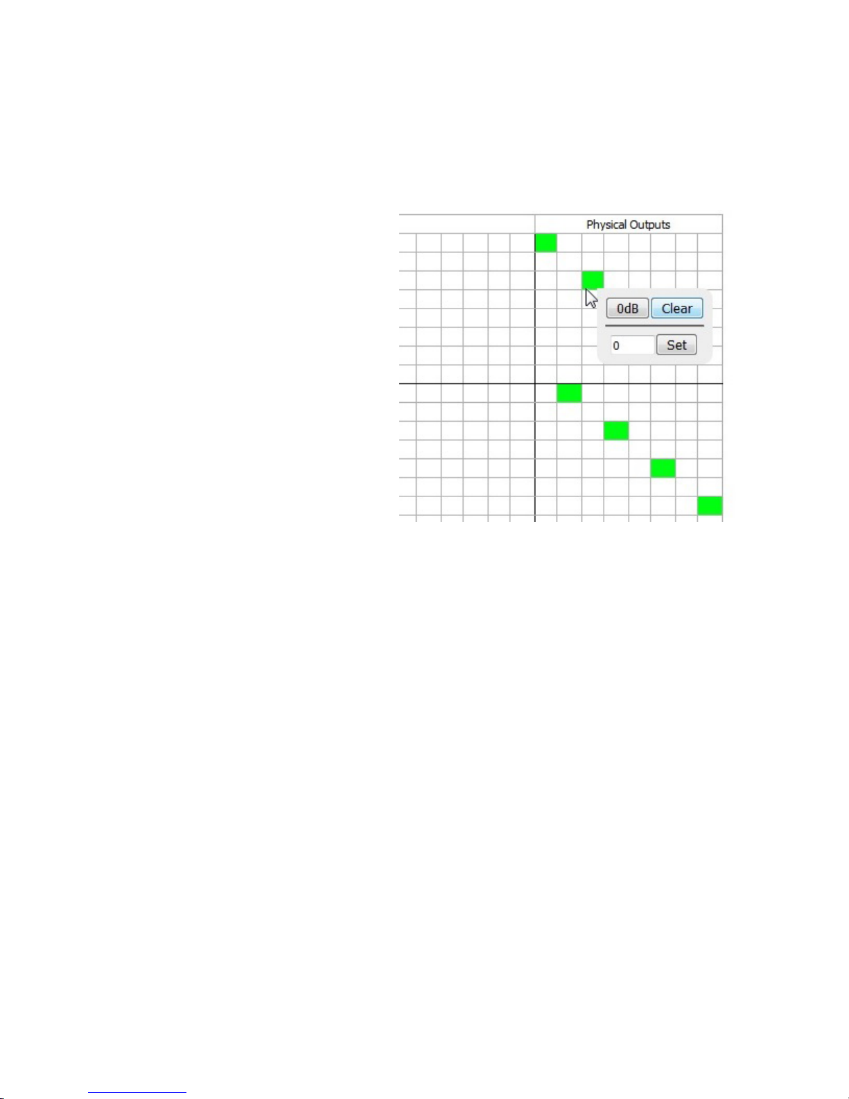
APPENDIX
If you’re savvy, a much faster way to clear the matrix from 8x8 mono mode is to copy and paste the following text into a
terminal logged in (raw) on port 93: (IN ALL CAPS)
LOGIN
MIX 2 17:CLEAR
MIX 4 19:CLEAR
MIX 6 21:CLEAR
MIX 8 23:CLEAR
MIX 9 18:CLEAR
MIX 10 18:CLEAR
MIX 11 20:CLEAR
MIX 12 20:CLEAR
MIX 13 22:CLEAR
MIX 14 22:CLEAR
CHAPTER 4
| 54
MIX 15 24:CLEAR
MIX 16 24:CLEAR
MIX 18 9:CLEAR
MIX 20 11:CLEAR
MIX 22 13:CLEAR
MIX 24 15:CLEAR
MIX 1 17:CLEAR
MIX 3 19:CLEAR
MIX 5 21:CLEAR
MIX 7 23:CLEAR
MIX 17 1:CLEAR
MIX 19 3:CLEAR
MIX 21 5:CLEAR
MIX 23 7:CLEAR
Once the mixer is cleared, we can begin setting up the I/O and the mix minus routing.
First, we need to route the physical inputs to the network sources (outputs to the network). Then we will route the physical
outputs to the Livewire Destinations. The idea is to route the VX’s output to physical outputs on the xNode. Then we want to
route Mix Minus to the VX’s input, but we want to mix caller 1’s audio in with the mix minus for caller 2 and vice versa.
The following image depicts this and the cross mix. The Inputs are highlighted in Red, the outputs in Blue and the cross mix in
Orange for creating the new mix minuses.
Page 64
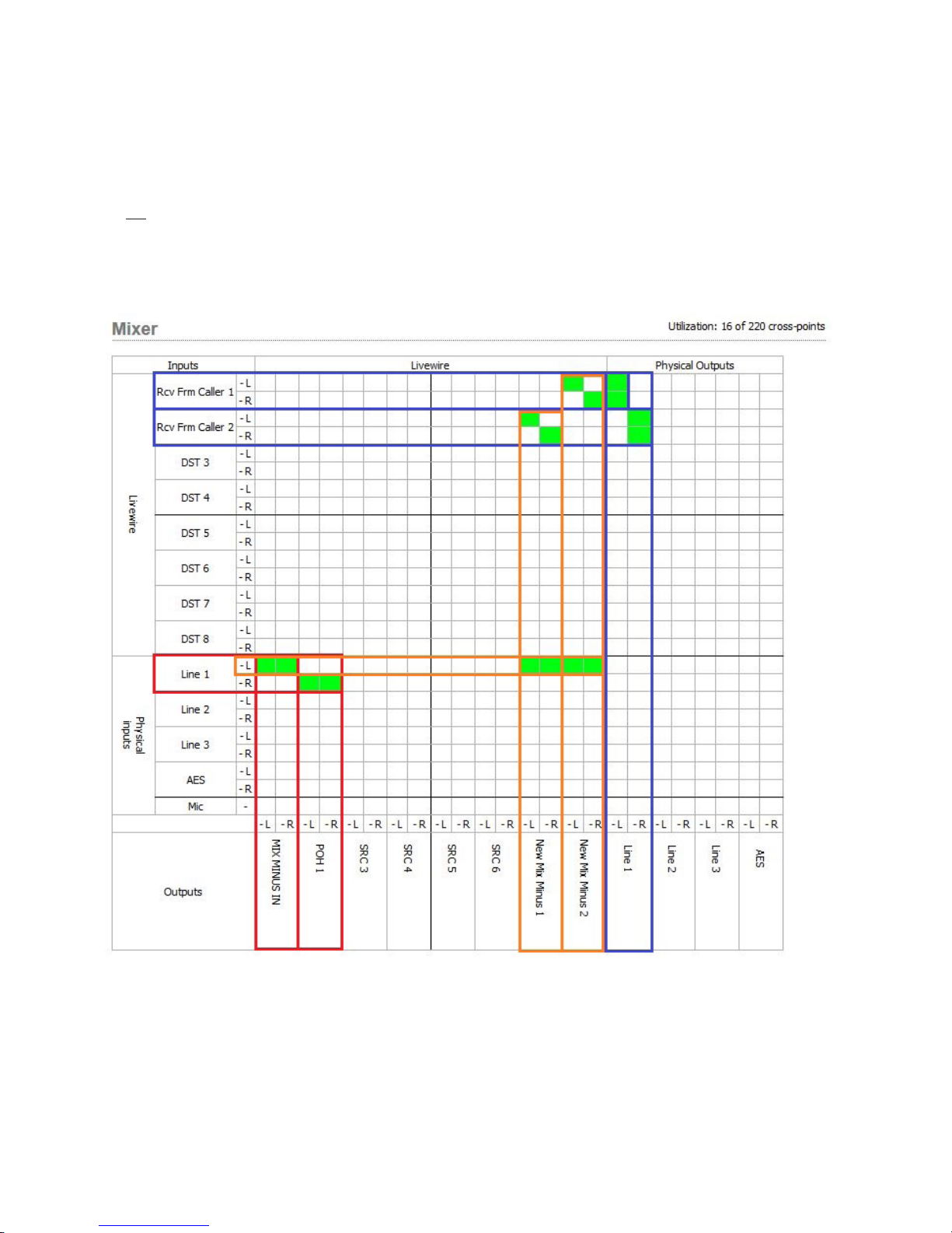
APPENDIX
Study the matrix and you’ll see how the mix is constructed for the mix minuses. You’ll also notice that the new mix minuses
are not routed to a physical output. We are just doing this to create new Livewire streams to drive the input of the VX. More on
this after the following table. To set a point, click it and select 0dB. Make sure to click the ENABLE CUSTOM MODE link if you
see it in the upper right-hand corner of the matrix.
(This is just an example. The xNode’s mixer can be setup using a virtually endless number of ways, so you don’t have to do it
this way. Poke around and do what’s right for you.)
CHAPTER 4
| 55
After setting this up, return to the SOURCES page and make note of the new mix minuses LW channel numbers. Finally, go
to the VX studio, click ADVANCED RECEIVE and enter the channel numbers for the new Mix Minuses in the fields and select
FROM SOURCE.
Page 65
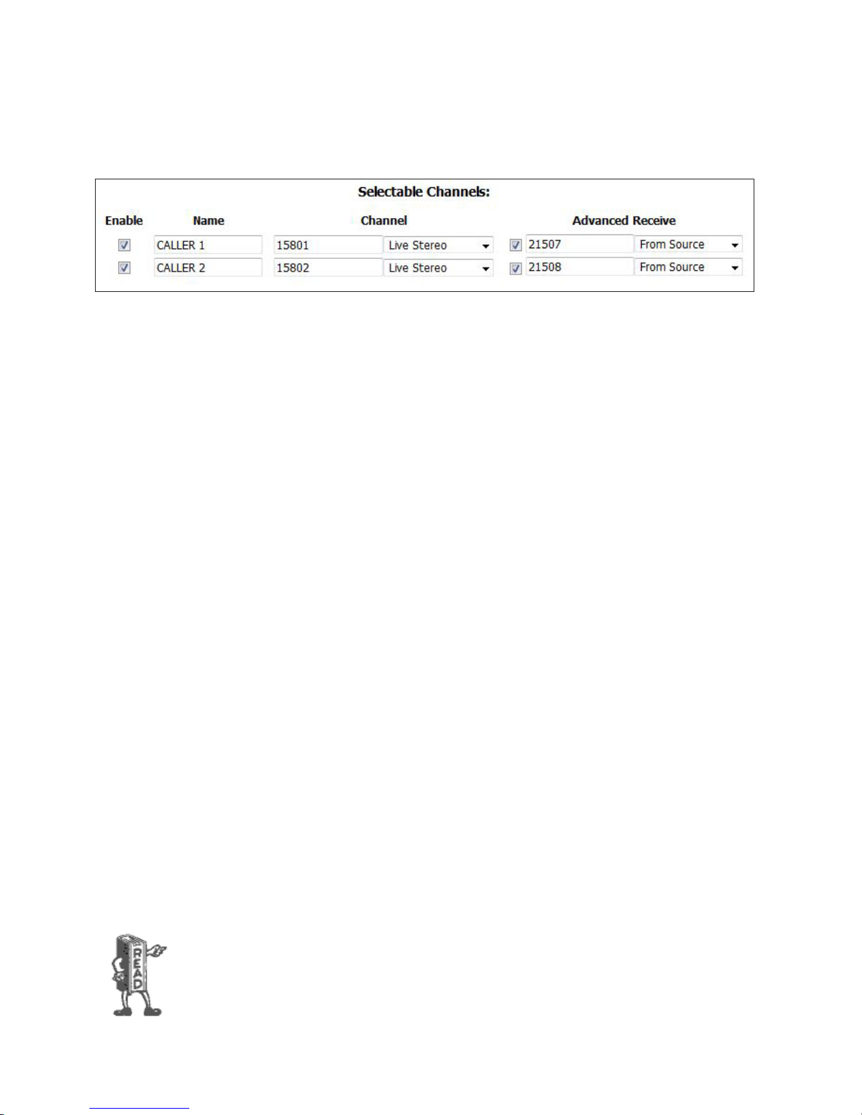
APPENDIX
A setup like this can be repeated using the remaining available sources and destinations. Keep in mind that routing mix
minuses this way uses up routes in the xNode so you will have less I/O for each route that is made internally. In this setup
Output Line 1’s left and right jacks will have the output of Hybrids 1 and 2 respectively.
CHAPTER 4
| 56
Operation with Fusion Consoles
Axia consoles can be used to control both fixed and selectable lines from the VX. Entering the VX Engine IP address into the
Fusion’s Show or Source profile (depending if it’s fixed or selectable) connects all the needed logic functions - line selection is
the main one, but muting for the VX sets is also handled.
Any VX set assigned to a studio and show shared with an Element will mute its ringer when the Element tells it to. Selectable
lines use the Element’s Call Control Module as the line selector. In this case, the IP address, show and studio are entered into
the PHONE section of the Fusion’s Show profile. It can be used in either 12 or 24 line mode, depending upon configuration.
In the former, two columns/faders are used; in the latter, one column/fader. The same module is used for either 12 or 24 line
operation. When 12 line mode, the left column of Status Symbols displays the line number and the right displays status. When
configured in 24 line mode, each active line is numbered with the number being shown when the line is idle (replacing the idle
“dot”). In the 12 line mode, the left row of buttons assigns lines to the left fader and the right row to the right fader. In the 24
line mode, both rows assign lines to the left fader. To assign to the right fader, push on, off or preview on the right fader which
activates flashing and displays PRESS LINE on the alpha display. Selecting a line assigns it to the right fader. To cancel the mode
before selecting a line, press the right drop button or the right channel off button.
When you need to be able to assign selectable lines to more than one or two faders, the Call Control Module can be expanded
using one or more Phone Fader modules. The additional Phone fader channels will work like the right fader on the Call Control
Module. You can quickly build multiple-line conferences on the fly, while keeping the usual one-call-after-another auto-drop
style operation on the left fader.
Usually, a VSet phone will be used in the studio along with the console to allow handset conversations. Taking a line on the VSet
will disconnect it from the Element, and vice-versa. The call will not be dropped.
Fixed lines can be configured directly to Fusion faders. Note that using only fixed lines and Phone Fader modules would give
you “Euro-style” operation, where each line has its own hybrid/fader and there is no line selector. There is no limit to fixed lines
vs. selectable in the VX, so you can have as many as you have available console faders.
Mix-minus is generated automatically in all Axia consoles. In Fusion Auto/Program 1 feed to source mode, the backfeed will be
generated by the PGM-1 bus “minus” the caller audio when the channel is ON. When the channel is OFF, Talkback will be the
source. Alternatively, Feed-to-Source can be fixed to Pgm 1, Pgm 2, Pgm 3, or Pgm 4. You can assign a line to a specific fader by
pushing the Set, OFF, ON, Hold, or PVW button on the fader channel before selecting the line. The fader channel alpha display
will toggle between source type and LINE N after a line is assigned.
There is much more explanation that this in the product manual for Fusion and Element. If you desire
more information to quench the thirst for knowledge, check it out!
Page 66
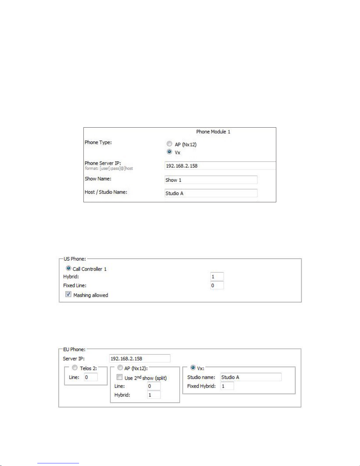
APPENDIX
CHAPTER 4
| 57
Setting it up
If you have a 2-Fader Phone Control Module, first thing to do is to set up the Fusion Show. If you don’t have a 2-fader/phone
module, skip this. The Fusion manual shows you how to do this, so we’ll be quick. Go to the PHONE page of the Fusion Show
profile. Set the PHONE TYPE to VX and enter the IP address of the system and the Studio name. This will need to be done for
each show on the Fusion that requires VX channels. If you want to bind a VX show to the VX studio when this console loads
a show profile, enter the VX Show name, otherwise leave SHOW NAME blank and the VX’s Studio will keep the current show
loaded when ever this console loads the profile.
After setting up the Fusion Show profile, set up the phone source profile in the Fusion. This is outlined in the Fusion manual,
so this is a general instruction. If the Fusion has a 2-fader call control module installed, choose the appropriate call controller
in the US PHONE section. For a selectable line, enter the hybrid number in the HYBRID field and check MASHING ALLOWED
to allow traditional conferencing. Enter a “1” to allow the hybrid to follow the left-hand column of line buttons on the module.
Enter a “2” to follow the right-hand column. If the channel is fixed, use the FIXED LINE field instead. A fixed line is fixed to a
specific hybrid.
If the console has no 2-Fader Phone Control modules or if you want to control a fixed hybrid from a specific channel strip, use
the EU PHONE configuration instead. Click the VX radio button, enter the VX’s IP address into the SERVER IP field. Then enter
the VX Studio name and the hybrid number in the FIXED HYBRID field. Note that the VX used in this example has an IP address
of 192.168.2.158 and that the IP address, Show names, and Studio names in your VX will most likely be different.
Remember that you’ll need to reload the show / source on the Fusion console before any changes will be seen.
Once you have a fixed fader set up, you can control the calls from the user buttons on the Fusion channel strip. User button “A”
will take and drop calls, while “B” places them on hold.
This configuration also applies to Element consoles with Engines running version 3.
Page 67
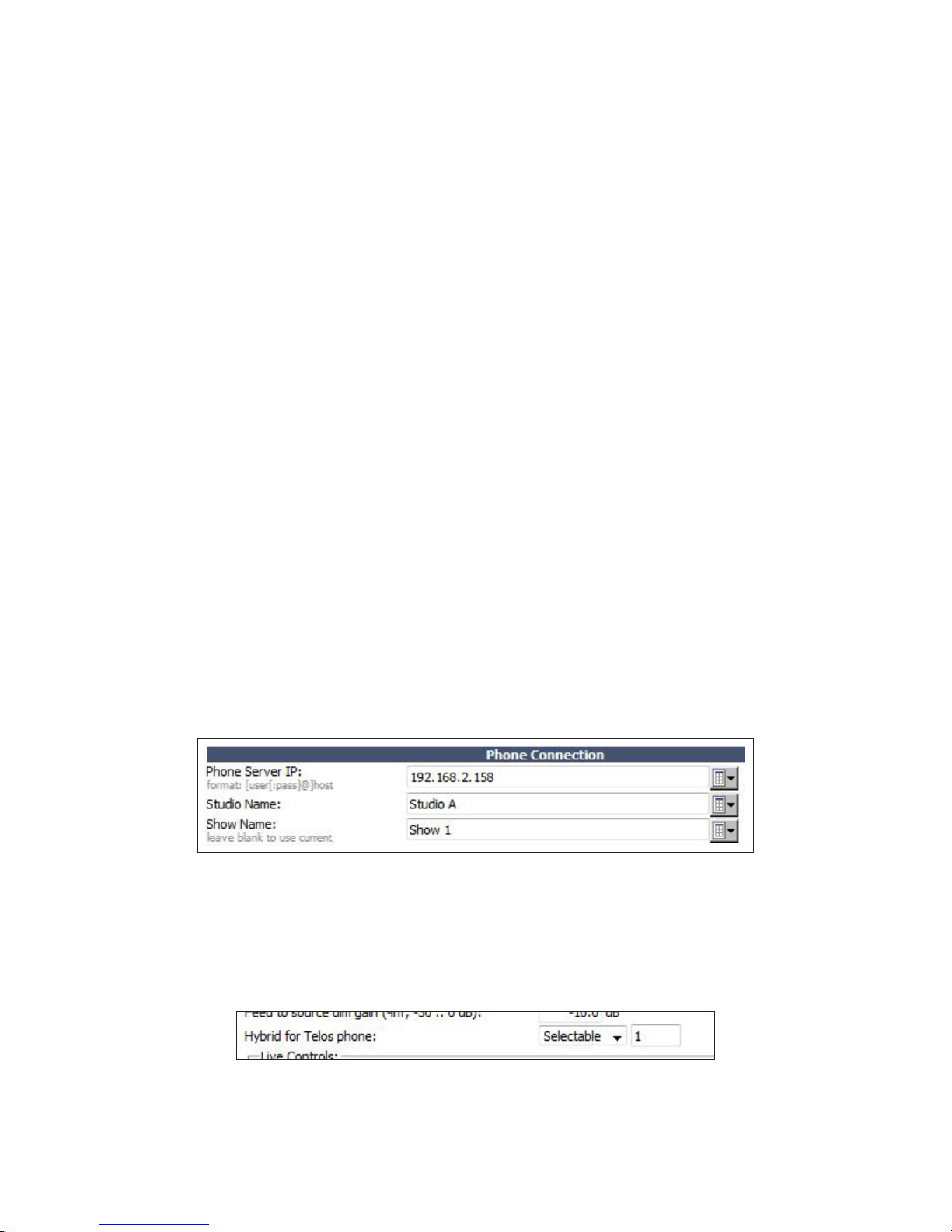
APPENDIX
CHAPTER 4
| 58
Ringer Mute
In the previous topic, we discussed GPIO and how physical ports don’t need to be wired when a Livewire console is being used.
In general, the ringer mute input in the VX Studio is going to get the same closure as the on-air tally light system. Just in case
this isn’t set up yet, here’s how.
In the MONITOR SECTION page of the Fusion show profile, you will find a field called GPIO channel for CR monitor under the
CONTROL ROOM MONITOR OPTIONS section. Enter an available livewire channel number here. Then, return to the VX’s
Studio configuration and create a new GPIO ACTION. Select MUTE RINGER from ACTIONS and enter this same Livewire
channel number. The closure happens on pin 1, so leave the control set to PIN 1 and the TYPE set to FROM GPIO.
When the Fusion Show and the VX Show are both reloaded, turning on the mic will mute the ringers on the VSets in addition
to the speakers in the control room. The same can be done with the Studio Monitor section if you have VSets in the studio that
should mute when one of those mics are turned on.
This channel number should still be routed to a physical GPIO port for connecting to the on-air tally lights.
Operation with QOR and iQx Consoles
Just like with Element and Fusion consoles, the QOR and iQx consoles offer the ability to control hybrids directly from the
surface. The iQ 6-Fader Expansion frame has a built-in call controller similar to the one found on the Fusion 2-Fader/Phone
control module. It works hand in hand with the VSet even though a VSet isn’t needed for talent control with one of these. The
setup is similar to the Fusion and Element, but is different enough for us to show you here. The QOR and iQx manuals have
more extensive sections covering Show and Source creation, so consult those texts for a more holistic approach.
Setting it up
First thing to do is to set up the QOR / iQx Show profiles. This is the one everybody forgets to do, so we’re doing it first. In the
console’s show profile, find the PHONE CONNECTION section. Enter the IP address of your VX into the PHONE SERVER IP
field. Then enter the VX Studio name in the STUDIO NAME field. Remember, the VX being used for this example has an IP of
192.168.2.158. Your IP, Studio, and Show names will most likely be different.
Note that you will be leaving the SHOW NAME field empty if you don’t want to bind this VX Studio to this VX Show when
loaded on this console.
Next, create a new Phone Source profile and configure it for the appropriate VX Channel. At the bottom of the profile, there’s a
HYBRID FOR TELOS PHONE field. If this is a selectable channel that is controlled from a 6-Fader Telco Expansion console, set
this to SELECTABLE and enter the hybrid number. Hybrid 1 is controlled by the left-hand column while Hybrid 2 is controlled
from the right-hand column.
If you have a fixed VX channel set up and you wish to use the channel strip’s SOFT key to control the hybrid (EU PHONE
mode), set HYBRID FOR TELOS PHONE to FIXED and enter the hybrid number.
Page 68
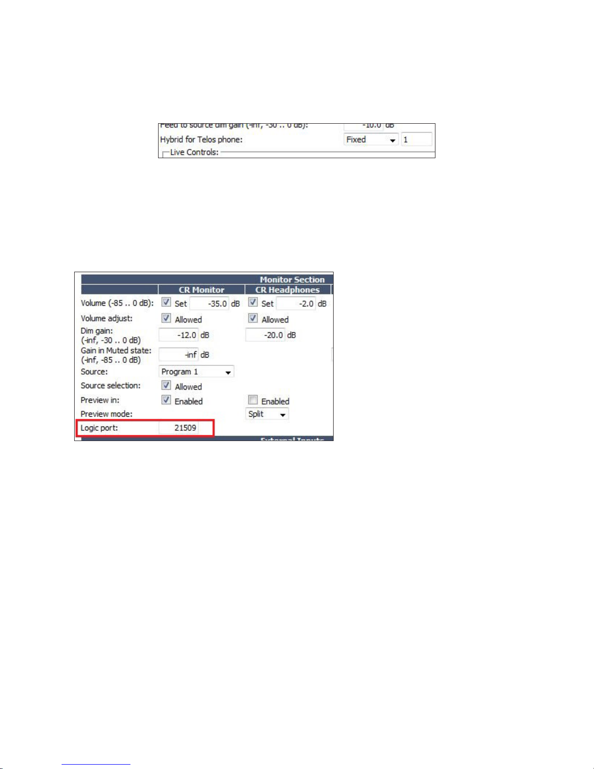
APPENDIX
Remember that the show profile needs to be set up in the QOR/iQx and that the show must be reloaded on the console to see
changes.
CHAPTER 4
| 59
Ringer Mute
In the xNode GPIO reference section, we talked about how physical GPIO doesn’t need to be wired up if a Livewire console is
being used. The VSet ringer mute is meant to be tied to the same closure as the on-air tally light system so that the ringers mute
at the same time as the CR Monitor speakers. If you haven’t done this yet, here’s how to set it up.
In the QOR or iQx show profile, go to the
MONITOR SECTION and look for the field called
LOGIC PORT under the CR MONITOR column.
Enter an available Livewire channel number here
and apply your changes. Then navigate back to the
VX Studio and create a new GPIO action. Select
RINGER MUTE as the ACTION and enter the same
Livewire channel number. The closure happens on
pin 1, so we will set PIN to PIN 1 and TYPE to
FROM GPIO.
When the iQ’s show and the VX’s Show are both
reloaded, turning on the mic will mute the ringers
on the VSets in addition to the speakers in the
control room. The same can be done with the
Studio Monitor section if you have VSets in the
studio that should mute when one of those mics are turned on.
This channel number should still be routed to a GPIO port for connecting to the on-air tally lights.
Setting up and Using “Dummy” Studios
Screening calls for multiple studios simultaneously
There’s often a need for VSet to be placed in location for call screening and nothing else. One way to do it is to use a VSet
in producer mode and switch it between shows when necessary. Another way is to have one VSet with lines for multiple
shows present so they can screen calls for these shows simultaneously. Reading through this manual, one may think this is an
impossible feat. We’ve got you covered. By creating a false or “dummy” studio with no hybrids (or channels) and a show to go
with it, we can make this happen really quickly.
Page 69
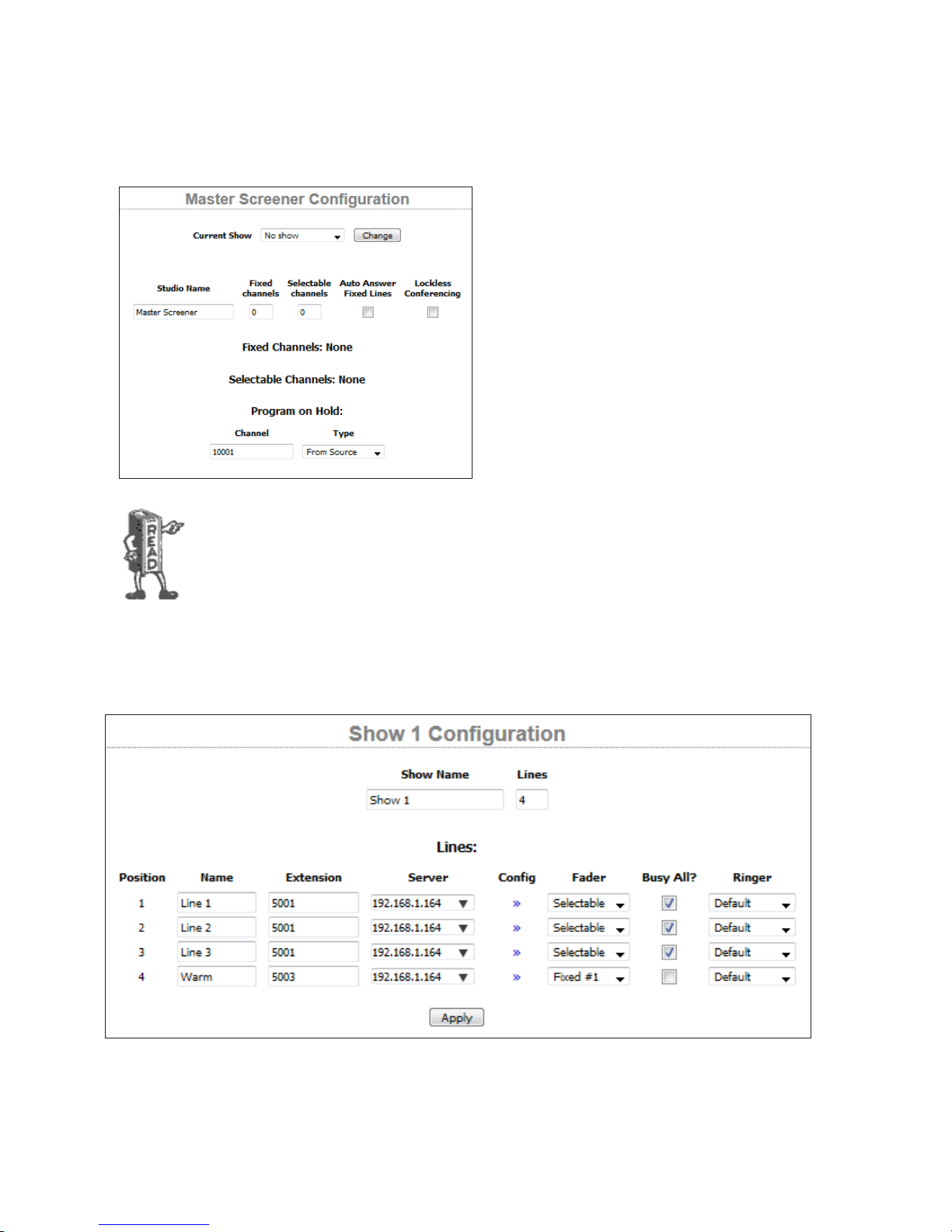
APPENDIX
CHAPTER 4
Let’s imagine a 2-studio facility with 3 request lines per
studio and one fixed line per studio to use as a warm line.
This gives us a total of 8 line positions for our VSet.
Before we can create a show with the collection of these lines,
we need to create a new Studio with no channels assigned;
a “dummy” studio. This will need program on hold so the
callers don’t get lost when placed on hold from this location.
(the only downside to this is there is only one POH possible
from this screening location).
Notice also that we can assign GPIO actions and indications to this studio. This allows us to do things
like hook up indicators to GPIO xNodes to alert someone that ANY phone line in any studio is ringing,
among others. See the GPIO section of this manual for a list of actions and indications available at the
GPIO interface.
| 60
Now that we have created a dummy studio, let’s move onto planning and creating the show.
First, we need to gather the line information from our two current shows. Note that you don’t have to log the Studio out of the
Show to view this information, so this can be done at any time during normal operation.
For Show 1, we make note that our request line extension is ‘5001,’ there are 3 of them and our warm line is ‘5003.’ We also
note that the warm line does not have the “Busy All” check box checked.
Page 70
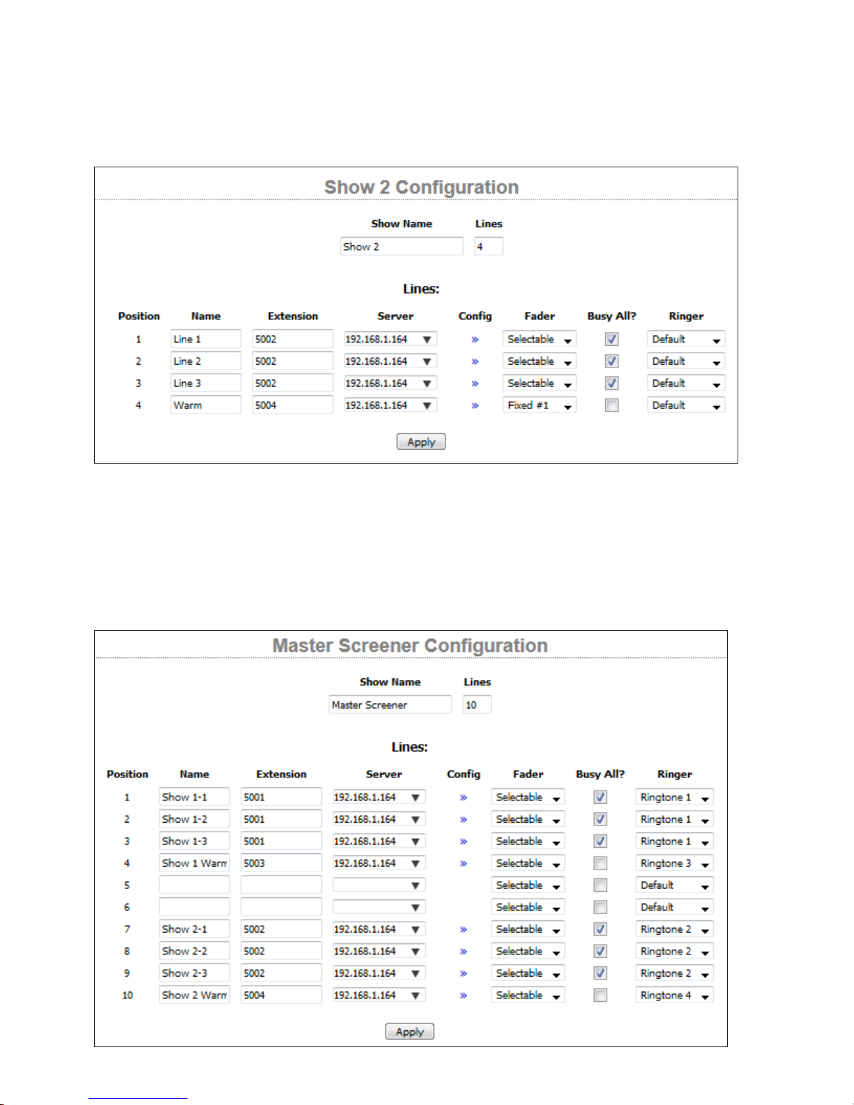
APPENDIX
Same story over here, except that the request lines use extension ‘5002’ and the warm line is ‘5004,’ which is also removed from
the busy/block all cue. We make note of all this, and go to the Configuration Shows page and begin creating a new show. Again,
this can all be done during normal operation since none of the things we are doing require logging a Studio out of a Show.
CHAPTER 4
| 61
Now, we need to create a new Show and assign these same extensions it. Notice that we’ve labelled both the Studio and the
Show the same to keep confusion at bay. In our example here, we created a show profile for 10 lines instead of 8 so that we
could manage the layout of the line positions on the VSet. (remember the VSet 12’s display is divided into two groups of 6)
leaving positions 5 and 6 blank, Show 1 is on the top display and Show 2 is on the bottom display of the VSet. This is totally
cosmetic and has no affect on operation. (except it dictates where on the VSet these lines show up)
Page 71
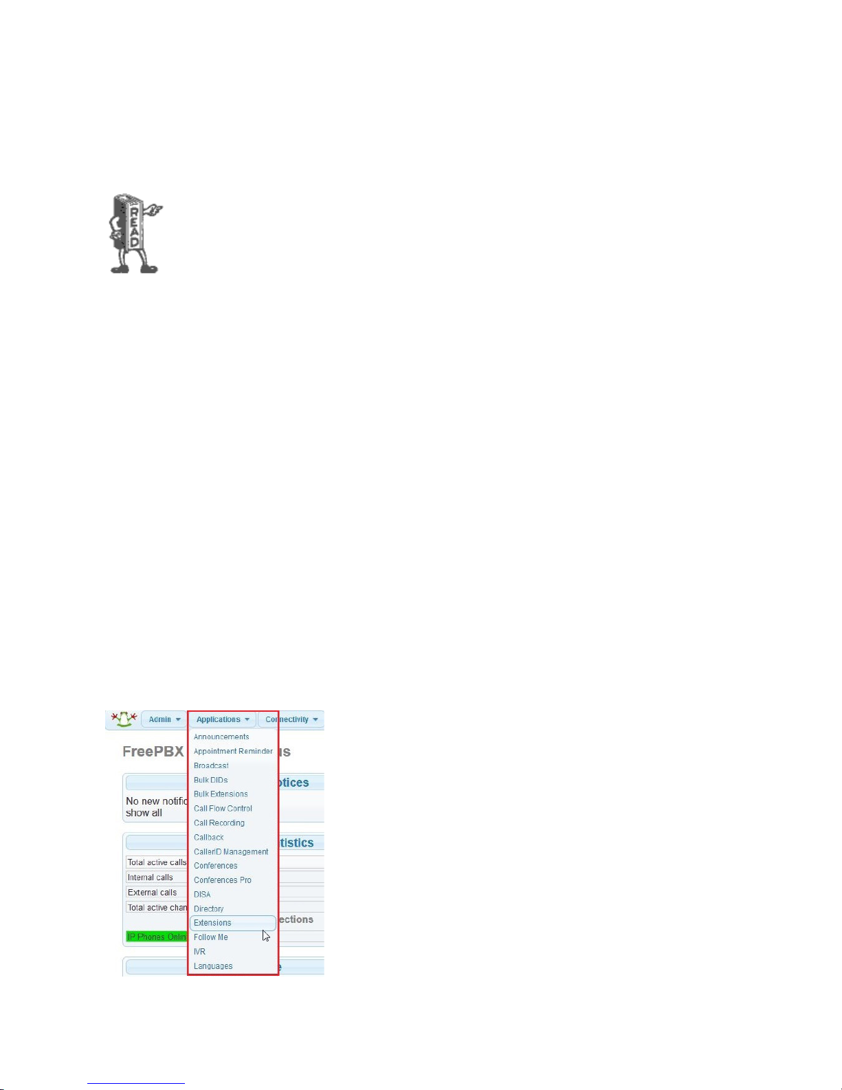
APPENDIX
Please note that this screener VSet and the actual Studio’s VSet have independent Block-All cues now.
This means if the dummy studio has the lines blocked, the actual Studios won’t be able to release
them. This could either be a good thing or a really bad thing. So if you don’t want the screener to be
able to activate Block-All for all the request lines in the entire facility, uncheck all the boxes under
“Busy All” and Block-All will do nothing in the dummy Studio/Show.
Notice that we are able to assign different ringtones to the different line positions. Please see the section of this manual
concerning ringtones for more information about this. Once you save your changes and log your VSet12 into the studio and
show, you’ll be able to make and take calls using the VSet hand/headset. You’ll be able to place calls on hold and they will
appear on hold in their respective studios.
Also since there are no channels configured in the dummy Studio, The VSet will operate as a producer VSet only an can’t
control the lines on the air, regardless of the Talent or Producer mode settings.
CHAPTER 4
| 62
Creating an Asterisk Extension for VX
Before we begin
You’re probably already aware of the raw processing power your VX is capable, but keep in mind that it is still a simple
device. The VX engine is no different from the IP phone sitting on your desk (or a group of them). The engine is a SIP
endpoint and is designed to work with extensions provided by a SIP server. The VX Engine is not a PBX, so it will not run
properly when it is given a trunk directly from the provider. For us, the SIP server of choice is the Asterisk PBX. Other makes
and models of SIP servers work in similar ways, so you can still use this document for guidance. Asterisk does not require
licensing and has no limitations regarding generic SIP endpoints. So if you are using another brand PBX, make sure this is not
the case. Also make sure to read this entire section before beginning any work.
Creating a Generic SIP Extension
First, log into your Asterisk’s web interface and navigate to APPLICATIONS > EXTENSIONS.
Page 72
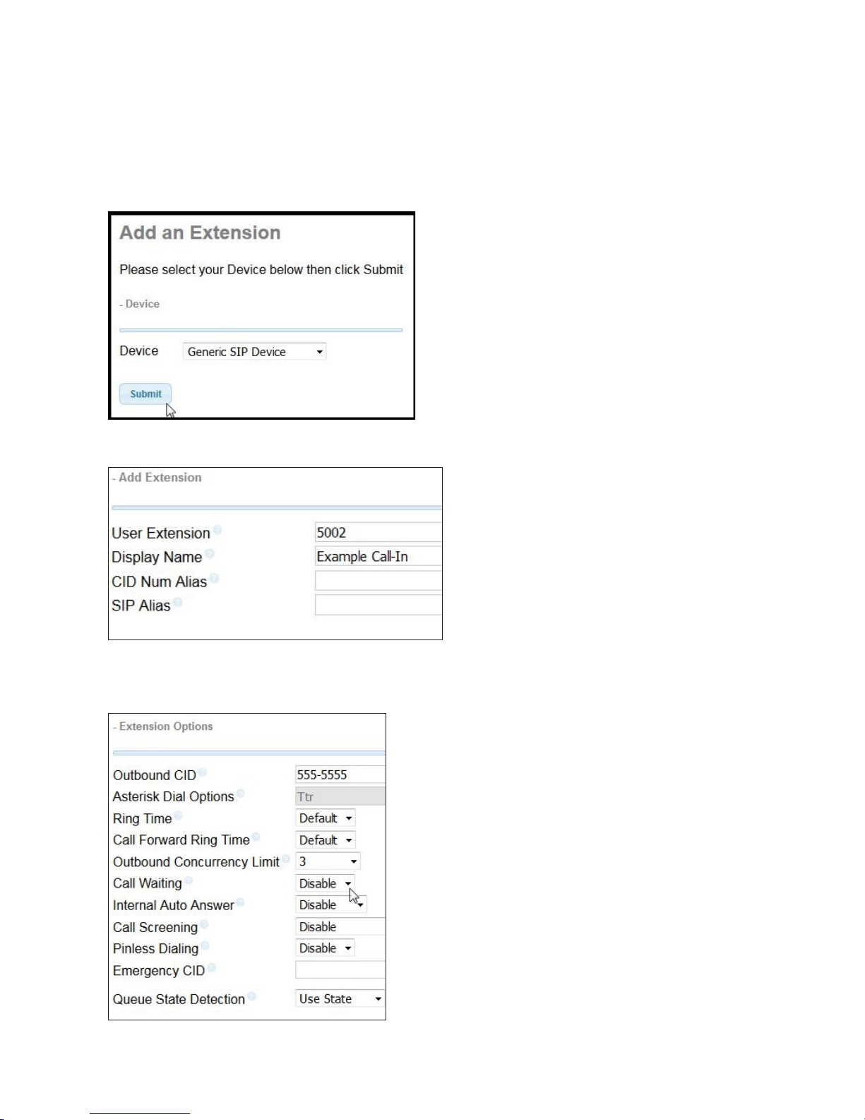
APPENDIX
This will bring you to the ADD AN EXTENSION page. In the dropdown box next to DEVICE, select Generic SIP device and click
Submit.
Clicking SUBMIT in the ADD AN EXTENSION window will take you to the ADD SIP EXTENSION page.
USER EXTENSION: Enter the extension number for the
system. In our example, the extension is 5002. Then in the
DISPLAY NAME field, enter the name you would like to
associate with the “line.” In our example we will use,
“Example Call-In.” You can make this whatever you want.
The remaining fields (CID Num Alias & SIP Alias) can be
left blank.
CHAPTER 4
| 63
Extension Options
Page 73
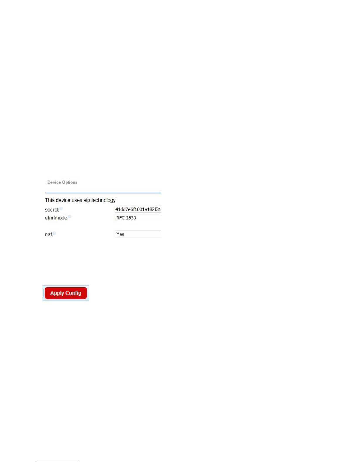
APPENDIX
OUTBOUND CID: Enter the phone number you wish to be displayed on the caller ID equipment at the far end when an outgoing
call is made from this extension. We’re using 555-5555 for this example, but you can use either your request line number or
your business office number; whichever suits the need for the line.
RING TIME: This can be left set to default, or to the maximum of 120
CALL WAITING: You may want to disable this to avoid having call waiting tones appear on the air with your callers. All the other
fields can be left in their default state.
CHAPTER 4
| 64
DID’s
DID is short for Direct Inward Dial. This is a phone number that you dial from an external telephone that rings a specific
extension. If you have a number for this purpose and the DID has already been set up in the Asterisk, enter it into the
INBOUND DID field. Otherwise leave this field blank.
Device Options
SECRET: Enter the extension password here. It can be what ever you want, but remember this because we will use it later. We
don’t recommend using the default unless you can remember it. ;-)
DTMF MODE: Set this to RFC2833. This is a standard DTMF protocol for SIP using G.711. Note that RFC2833 is not always
supported with HD codecs like G.722. So, if you are using an HD codec, DTMF for navigating menus, etc. may not work.
There is no need to configure any other options for the extension, so you can now scroll down to the bottom and click SUBMIT.
If there are any errors in your config, the software will let you know now. If you’ve done it correctly, you will be brought back
to the ADD AN EXTENSION screen. Click the red APPLY CONFIG button at the top of the page right now so your changes take
effect. At this point, you can add another extension and repeat the above until you have all the extensions you need to complete
the job.
IMPORTANT: The VX can register multiple line positions to the same extensions, so you do not need to create a rollover or a
hunt group for request lines. Therefore, you’ll only need one extension per studio for request lines, etc.
Now, let’s go over to the VX and get it set up.
Page 74
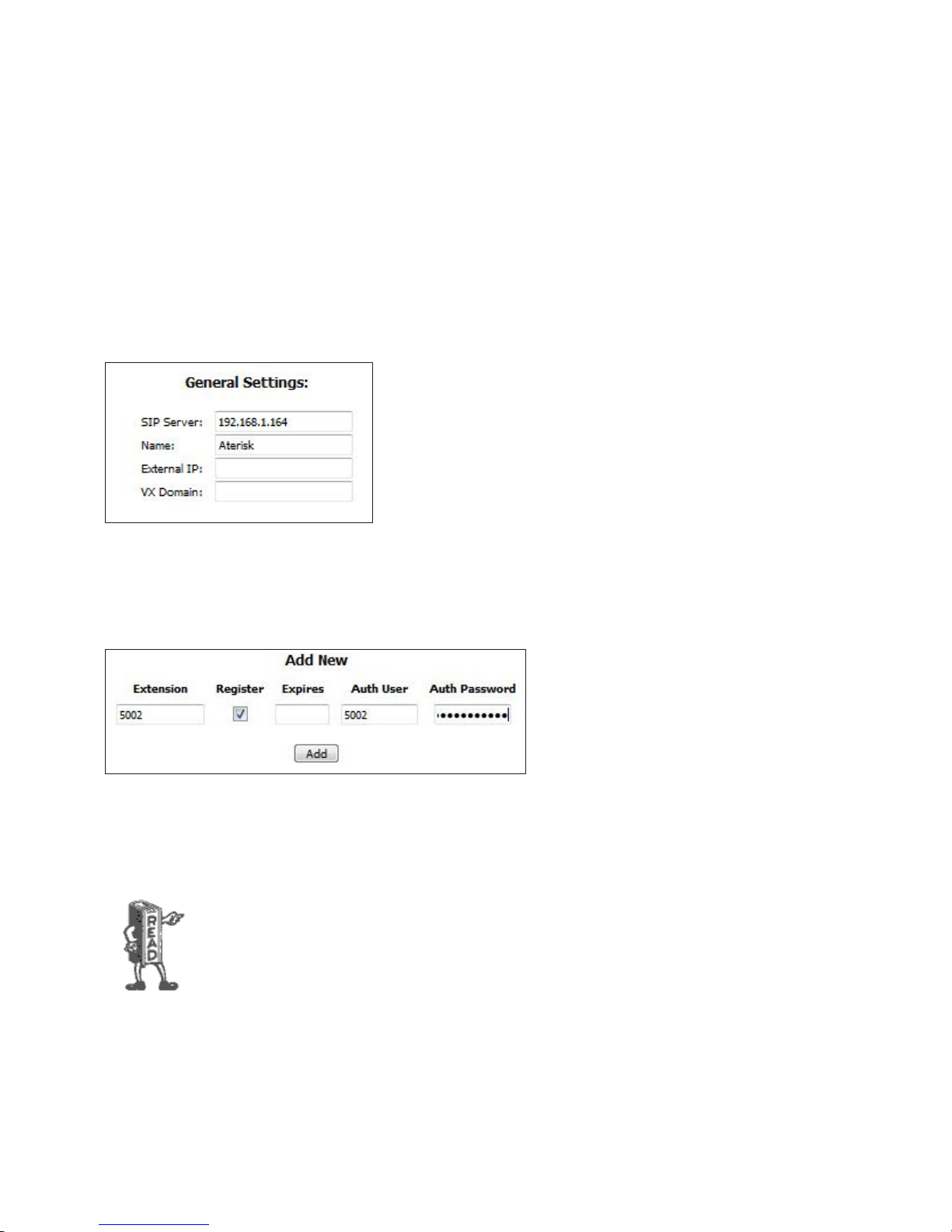
APPENDIX
CHAPTER 4
| 65
Conguring VX to talk to Asterisk
This is deep into the appendix so by this point, we presume that you have the VX installed with the WAN port on the same
network as the Asterisk server. If you haven’t read that section of this manual, now is a good time. For understanding’s sake, we
will repeat some of what we discussed there:
First, go to the SIP page in the VX’s UI.
At the bottom, you will notice a section called ADD NEW with a SERVER field. Enter the IP address for the Asterisk server here
and click ADD.
This will take you to the main configuration page for the server. Enter a memorable name for the server in the NAME field and
click the APPLY button directly beneath the General Settings fields.
Next, find the ADD NEW section of the page. Enter the extension number into the EXTENSION and AUTH USER fields, check
the REGISTER check box, and enter the password you set for SECRET back when we were configuring the Asterisk in the AUTH
PASSWORD. Remember? Now click ADD.
If you configured multiple extensions, repeat this process until you are done.
REMEMBER: You do not need to have a separate extension set up for each request line position in a studio. If you want to have
multiple line positions registered to the same number in a roll-over or hunt group configuration, VX will do that for you. It’s
really cool!
The Next step is to add the extension(s) to a VX Show prole and assign the show to a VX Studio.
You’ll nd it described in chapter 2 of this manual.
Page 75
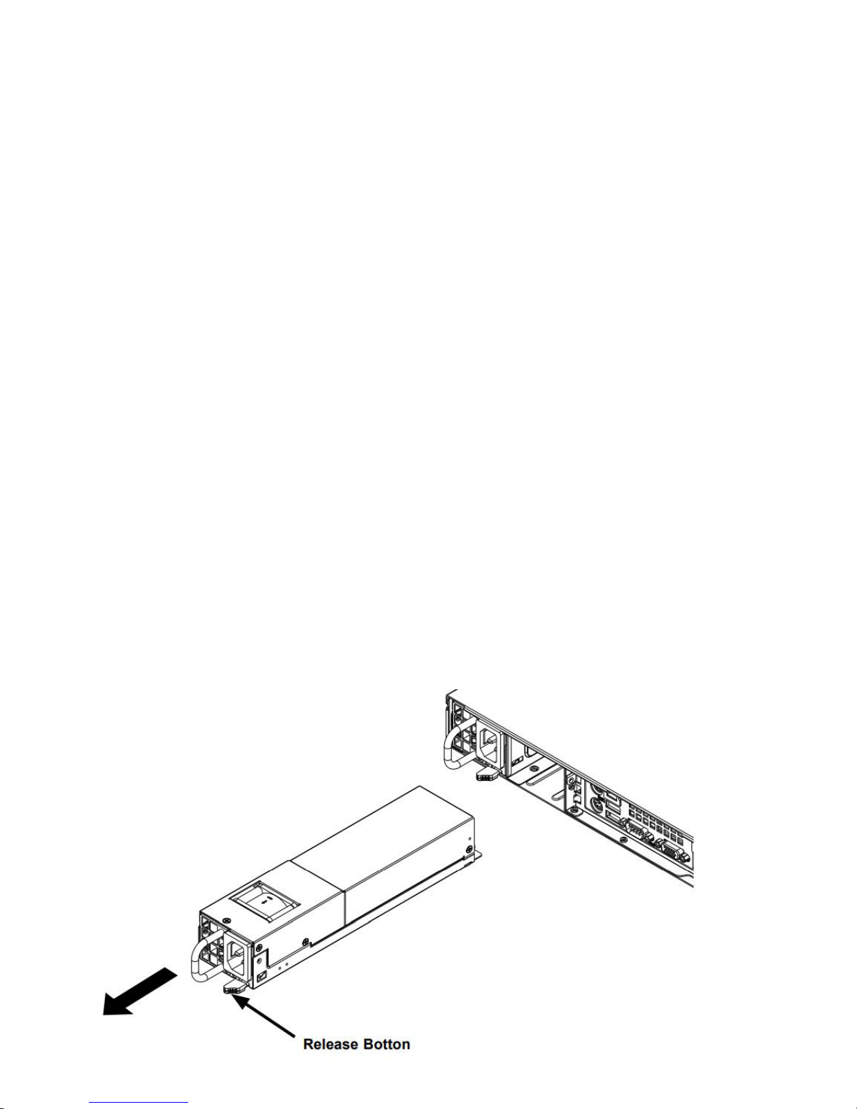
APPENDIX
CHAPTER 4
| 66
Asterisk – Rebooting and Accessing
Normally, a PBX should never need to be rebooted. But we all know that computers simply need to be rebooted from time to
time. There are multiple theories about right and wrong ways to reboot a machine, so we thought we’d talk about it.
If you have an Asterisk PBX built by Announcement Technologies, this note applies to you. PBX’s built by other vendors will
not work exactly this way:
1. Asterisk should always be shutdown gracefully using the following method:
a. Open a terminal window.
b. At the command prompt type: shutdown -h now
c. Asterisk will halt and power off.
2. To start Asterisk from a power off condition, press the power button inside the front door.
3. After Asterisk has booted the screen will show the Linux login. (Asterisk will process calls whether logged in or not)
To log in:
a. User name is: root
b. Password is: telos7225
4. Once logged into Linux, the screen will be at the Linux command line prompt. To start the X Window System (Linux
version of Windows) simply type: startx
5. The Asterisk GUI has a user and password (which is memorized in Firefox).
a. User: wwwadmin
b. Password: telos7225
Changing Power Supplies
The VX Enterprise and VX Prime Plus come with two 400Watt redundant power supplies. The supplies are auto autoswitching capable. This enables it to automatically sense and operate at a 100VAC to 240VAC input voltage. An amber light
will be illuminated on the power supply when the power is off. An illuminated green light indicates that the power supply is
operating.
Page 76

APPENDIX
These supplies can be changed without powering down the system:
1. Press the release button on the failed power supply.
2. Use the handle to gently slide the power supply out the back of the chassis.
3. Replace the failed power module with another of the same model.
4. Slide the new power supply module into the power supply bay until it clicks into the locked position.
WARNING: The bulk capacitors in all switch mode power supplies can hold a very substantial charge
for an extended period of time. The user is at risk of electrocution if proper safety is not practiced. DO
NOT disassemble the power supply. There are no user serviceable parts inside. Contact Telos Support
for replacement.
CHAPTER 4
| 67
Page 77

APPENDIX
Resources and Tools
Internet Speed tests
www.speakeasy.net
www.speedtest.net/
Internet VOIP Jitter Test
myspeed.visualware.com/indexvoip.php (free)
Packet “snier”
www.wireshark.org/download.html (free)
VoIP Soft phone” SIP PC clients
X-Lite “Soft phone” SIP PC client (free)
CHAPTER 4
| 68
www.counterpath.com/x-lite.html
Ekiga, free open source SoftPhone - ekiga.org/
Linphone open source VOIP phone - www.linphone.org/
Open Source PBX Distributions
www.digium.com
pbxinaflash.net/
www.freepbx.org/
www.asterisk.org/
Commercial PBX Products
www.microsoft.com/voip
www.lg-nortel.com
www.trixbox.org
www.siemens.com/hipath
www.mitel.com
www.digium.com
Page 78

APPENDIX
CHAPTER 4
| 69
Gateway products and suppliers
Note: gateways are often difficult to set up and POTS gateways in particular have shortcomings that are mainly limitations
of POTS itself. While the hardware mentioned below is excellent and we’ve tested with all of it. Native SIP is always the
best way to go. POTS should not be chosen because it is “safe”. POTS lines are far less reliable today, mostly because service
providers, many deregulated now, do not maintain their outside cable plant as they once did. We suggest that if you use POTS,
it is primarily for “backup” or emergency use. Some features will not work with POTS gateways (Busy out, call disconnect
supervision, and often Caller ID), and further, transmission will not be as loud, clear or natural sounding as with VOIP/SIP. The
companies below make great products, but they are limited by POTS technology for performance and dependability. Telos may be
able to provide very limited help with gateway support, but we actively discourage its use for the reasons mentioned above.
www.patton.com/voip/
We have tested Patton gateways, such as the model 4940 for T1/E1 and ISDN PRI. The Patton gateways for POTS (FXO) and
ISDN BRI are also satisfactory.
www.grandstream.com
www.audiocodes.com
www.cisco.com
www.digium.com
VoIP/SIP equipment suppliers
www.voiplink.com
www.telephonydepot.com
www.rockbottomvoip.com/
Telephony Discussion and VoIP news sites
www.sipforum.org
www.telos-systems.com
www.voipforums.com/
www.voipuser.org/forum_index.html
www.broadbandreports.com/forum/voip
forum.voxilla.com/
https://www.fiercetelecom.com/telecom
Page 79

APPENDIX
CHAPTER 4
| 70
SIP Information and suggested reading
A Request for Comments (RFC) is a memorandum published by the Internet Engineering Task Force (IETF) describing
methods, behaviors, research, or innovations applicable to the working of the Internet and Internet-connected systems. The
IETF adopts some of the proposals published as RFCs as Internet standards. These are available at: www.ietf.org/rfc. Among
those relevant to VoIP and SIP are:
RFC 1889: Real Time Protocol (RTP) - original version
RFC 3550 - Real Time Protocol (RTP) - latest version
RFC 1890: Real Time Protocol Audio Video Profiles (RTP/AVP) - original version
RFC 3551: Real Time Protocol Audio Video Profiles (RTP/AVP) - latest version
RFC 2327: Session Description Protocol (SDP) - original version
RFC 4566 - Session Description Protocol (SDP) - latest version
RFC 2543: Session Initiation Protocol (SIP) – original version
RFC 3261: Session Initiation Protocol (SIP) – latest version
RFC 3264: Codec negotiation
A. H. Inglis. “Transmission Features of the New Telephone Sets,” Bell System Technical Journal 17 (1938): 358-380. (Just for
fun. Waaay back, Mr. Inglis proposed “high-fidelity” phones, noting that cost was the only barrier to better audio quality in the
telephone network and predicting it would become common in the future. Took awhile…)
Books
Henry Sinnreich and Alan B. Johnston. Internet Communications Using SIP, John Wiley & Sons, Inc., New York, 2001.
Gonzalo Camarillo. SIP Demystified, McGraw-Hill, New York, 2002.
Steve Church and Skip Pizzi. Audio over IP: Building Pro AoIP systems with Livewire, Focal Press, Burlington,MA and Oxford UK.
2010 (Mighty fine fellas, these guys. Good book, too!)
Jonathan Davidson and James Peters. Voice over IP Fundamentals, Cisco Press, Indianapolis, 2000.
J. Alexander, C. Pearce, A. Smith, and D. Whetten, Cisco Call Manager Fundamentals 2nd Edition, Cisco Press, Indianapolis, 2006.
D. Au, B. Choi, R. Haridas, C. Hattingh, R. Koulagi, M. Tasker, L. Xia. Cisco IP Communications Express: Call Manager Express with
Cisco Unity Express, Cisco Press, Indianapolis, 2005.
Oliver Hersent, David Gurle, and Jean-Pierre Petit, IP Telephony: Packet-Based Multimedia Communications Systems, Addison-
Wesley, Reading, MA, 1999.
Switching to VOIP – O’Reilly
VOIP Hacking - O-Reilly
Asterisk - O-Reilly
Page 80

APPENDIX
CHAPTER 4
Specications
General
♦ Telos 5th-generation Adaptive Digital Hybrids
♦ Maximum number of hybrids: 120, when used with a-Law or u-Law codecs for VoIP lines. (Higher quality codecs, such
as G.722, consume more system resources and result in a decreased number of total lines available.) A Telos system
engineering consultation is required for any system configuration over 72 hybrids.
♦ Maximum number of SIP numbers: unlimited
♦ Maximum active on-air calls: 120
♦ Maximum on-air calls on one fader: 12
♦ One rack unit - 1.75”H x 19”W x 15.5”D (44 x 483 x 394 mm)
Analog Inputs (with Telos Alliance xNode)
♦ Input Impedance: >40 k Ohms, balanced
| 71
♦ Nominal Level Range: Selectable, +4 dBu or -10dBv
♦ Input Headroom: 20 dB above nominal input
Analog Outputs (with Telos Alliance xNode)
♦ Output Source Impedance: <50 Ohms balanced
♦ Output Load Impedance: 600 Ohms, minimum
♦ Nominal Output Level: +4 dBu
♦ Maximum Output Level: +24 dBu
Digital Audio Inputs and Outputs
♦ Reference Level: +4 dBu (-20 dB FSD)
♦ Impedance: 110 Ohm, balanced (XLR)
♦ Signal Format: AES-3 (AES/EBU)
♦ AES-3 Input Compliance: 24-bit with selectable sample rate conversion, 32 kHz to 96kHz input sample rate capable
♦ AES-3 Output Compliance: 24-bit Digital Reference: Internal (network timebase) or external reference 48 kHz, +/- 2 ppm
♦ Internal Sampling Rate: 48 kHz
♦ Output Sample Rate: 44.1 kHz or 48 kHz
♦ A/D Conversions: 24-bit, Delta-Sigma, 256x oversampling
♦ D/A Conversions: 24-bit, Delta-Sigma, 256x oversampling
♦ Latency <3 ms, mic in to monitor out, including network and processor loop
Page 81

APPENDIX
Frequency Response
♦ Any input to any output: +0.5 / -0.5 dB, 20 Hz to 20 kHz
Dynamic Range
♦ Analog Input to Analog Output: 102 dB referenced to 0 dBFS, 105 dB “A” weighted to 0 dBFS
♦ Analog Input to Digital Output: 105 dB referenced to 0 dBFS
♦ Digital Input to Analog Output: 103 dB referenced to 0 dBFS, 106 dB “A” weighted
♦ Digital Input to Digital Output: 138 dB
Total Harmonic Distortion + Noise
♦ Analog Input to Analog Output: <0.008%, 1 kHz, +18 dBu input, +18 dBu output
♦ Digital Input to Digital Output: <0.0003%, 1 kHz, -20 dBFS
♦ Digital Input to Analog Output: <0.005%, 1 kHz, -6 dBFS input, +18 dBu output
♦ Crosstalk Isolation, Stereo Separation, and CMRR
CHAPTER 4
| 72
♦ Analog Line channel to channel isolation: 90 dB isolation minimum, 20 Hz to 20 kHz
♦ Analog Line Stereo separation: 85 dB isolation minimum, 20 Hz to 20 kHz
♦ Analog Line Input CMRR: >60 dB, 20 Hz to 20 kHz
IP/Ethernet Connections
♦ One 100/1000BASE-T Ethernet via RJ-45 LAN connection
♦ One 100/1000BASE-T Ethernet via RJ-45 WAN connection
Processing Functions
♦ All processing is performed at 32-bit floating-point resolution
♦ Send AGC/limiter
♦ Send filter
♦ Gated Receive AGC
♦ Receive filter
♦ Receive dynamic EQ
♦ Ducker
♦ Sample rate converter
♦ Line Echo Canceller (hybrid)
♦ Acoustic Echo Canceller
Page 82

APPENDIX
CHAPTER 4
Power Supply AC Input
♦ Hot-swap capable dual-redundant internal auto-ranging power supplies. 90 – 132 / 187 – 264 VAC, 50Hz/60Hz. IEC
receptacle, internal fuse.
♦ Power consumption: 150 Watts
Operating Temperatures
♦ -10 degree C to +40 degree C, <90% humidity, no condensation
Studio Audio Connections
♦ Via Livewire IP/Ethernet. Each selectable group and fixed line has a send and receive input/output
♦ Each studio has a Program-on-Hold input
♦ Each Acoustic Echo Canceller has two inputs (signal and reference) and one output
♦ Livewire+™ AES67 equipped studios may take and supply audio directly to/from the network. Telos Alliance xNodes are
available for pro analog and AES3 (AES/EBU) breakout.
♦ VX Enterprise supports AES67 connectivity.
| 73
Telco Connections
♦ Audio: standard RTP. Codecs: g.711μ-Law and A-Law, and G.722.
♦ Control: standard SIP Endpoint, ISDN PRI/T-1, ISDN BRI and POTS may be supported with the appropriate interfaces
using an Asterisk Open source PBX.
Regulatory
♦ North America: FCC and CE tested and compliant, redundant power supplies are UL approved.
♦ Europe: Complies with the European Union Directive 2002/95/EC on the restriction of the use of certain hazardous
substances in electrical and electronic equipment (RoHS), as amended by Commission Decisions 2005/618/EC,
2005/717/ EC, 2005/747/EC (RoHS Directive), and WEEE.
Page 83

APPENDIX
Telos VX Tech Quick Reference Pages
Default Passwords:
(There are no default passwords, so leave the password fields blank)
VX Engine username = user , password =
VSet Telephone username = user , password =
Default IP Addresses:
VX Engine ‘Network’ interface = 192.168.2.200 (front panel settable)
VX Engine ‘WAN’ interface IP address: OFF by default, no IP set.
SIP Parameters
Codecs supported as of 2018: g.711 alaw and ulaw. g.722.
SIP Stations
CHAPTER 4
| 74
TCP/IP Ports and protocols used by the VX System
♦ 80 HTTP (TCP/ LAN Port only)
♦ 843 TCP Server for Flash socket policies - it is required for the meters applet
to make an LWCP connection to the VX.
♦ 22 SSH (TCP/LAN port only)
♦ 8080 HTTP (TCP/ WAN port only when activated)
♦ 1022 SSH (TCP/ WAN port only when activated)
♦ 5004 used internally by DSP engine (UDP) Livewire ports
♦ 5060 SIP UDP used for call setup
♦ 40000-40050 used for Vset handset audio (unicast)
♦ 62000 through 62513 SIP RTP (UDP/WAN port when activated)
♦ 20518 LWCP (Live Wire Control Protocol TCP/WAN port when activated)
♦ Some port numbers may be changed by the customer on the WAN interface for security and flexibility.
Page 84

APPENDIX
CHAPTER 4
| 75
VSet Phone Set
VSet Telephone default IP address: 192.168.0.201 (front panel settable)
Default username and password:
username = user
password =
telnet requires no password
Websocket Ports and protocols used by the VSet:
80 HTTP (TCP)
23 Telnet (TCP)
20518 (TCP) Livewire Control protocol port
40000-40050 (UDP) Vset Audio
Power Over Ethernet (PoE)
The VSet uses standard 802.3af Power Over Ethernet (POE) and consumes 15.4 watts Please consider this relatively high
power consumption rate when choosing your POE source.
The original IEEE 802.3af-2003PoE standardprovides up to 15.4 W of DC power (minimum 44 V DC and 350 mA) on each
port. Only 12.95 W is assured to be available at the powered device as some power is lost in the cable.
Page 85

C
Telos Alliance Limited Warranty
Telos Alliance Warranty
For the latest Telos Alliance warranty, visit: telosalliance.com/warranty.
Page 86

1241 Superior Ave. • Cleveland, Ohio, 44114, USA • +1.216.241.7225 • TelosAlliance.com
© 2019 TLS Corp., All Rights Reserved. C19/17050 • P/N: 1490-00210-001 USER MANUAL: VX Enterprise/VX Prime+
 Loading...