

Page 1
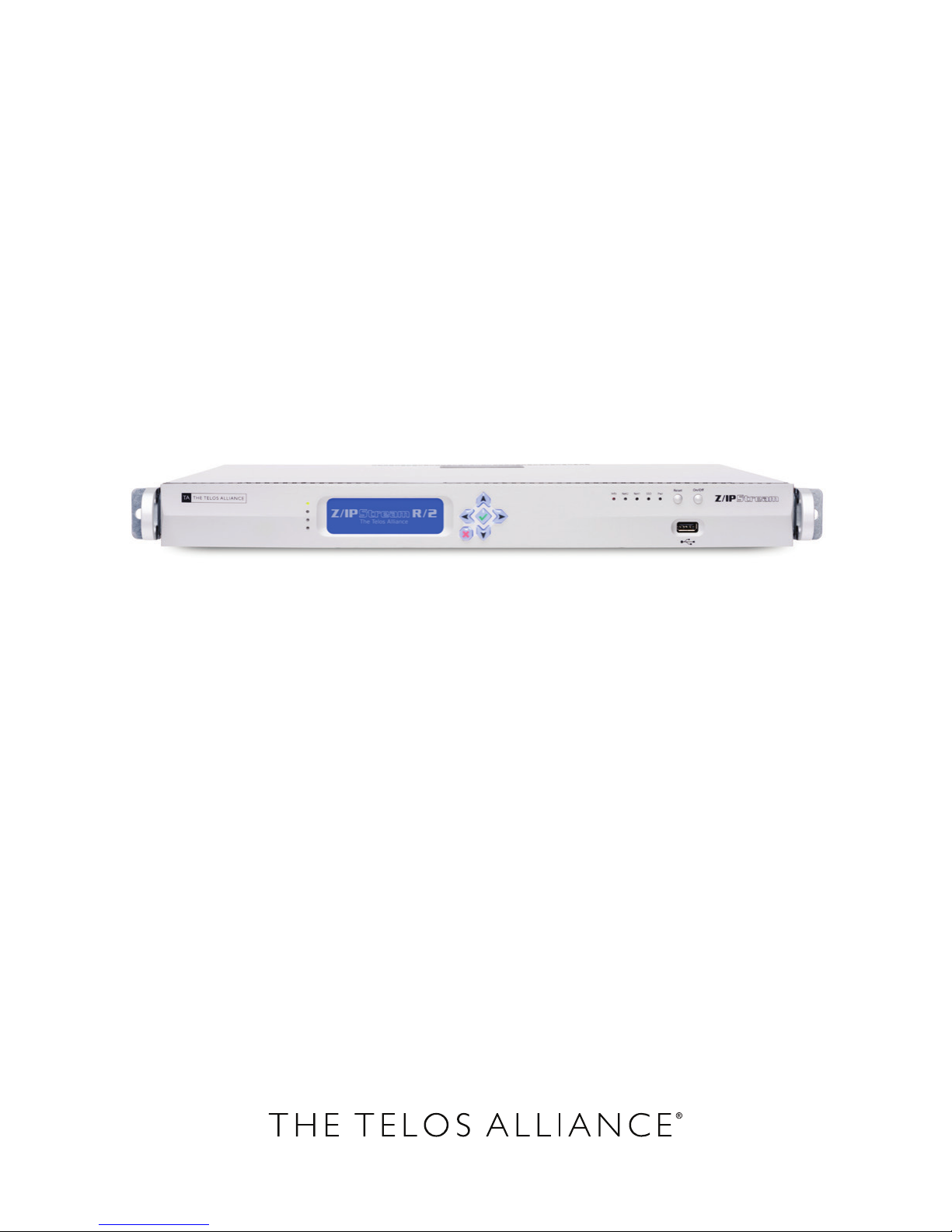
Z/IPSTREAM R/2
8 Channels of Z/IPStream, One Box.
USER’S MANUAL
Z/IPStream R/2 Manual for Software v1.01.35
Applies to: 2001-00441 through 2001-00454 and 2201-00034 through 2201-00036
Page 2

Notices and Cautions
CAUTION:
The installation and service instructions in this manual are for use by qualified personnel only. To avoid electric
shock, do not perform any servicing other than that contained in the operating instructions unless you are qualified
to do so. Refer all servicing to qualified personnel.
This instrument has an autoranging line voltage input. Ensure the power voltage is within the specified range of
100-240v. The ~ symbol, if used, indicates an alternating current supply.
This symbol, wherever it appears, alerts you to the presence of uninsulated, dangerous voltage inside the
enclosure – voltage which may be sufficient to constitute a risk of shock.
This symbol, wherever it appears, alerts you to important operating and maintenance instructions.
Read the manual.
CAUTION: DOUBLE POLE/NEUTRAL FUSING
The instrument power supply incorporates an internal fuse. Hazardous voltages may still be present on some of the
primary parts even when the fuse has blown. If fuse replacement is required, replace fuse only with same type and
value for continued protection against fire.
| II
WARNING:
The product’s power cord is the primary disconnect device. The socket outlet should be located near the device
and easily accessible. The unit should not be located such that access to the power cord is impaired. If the unit is
incorporated into an equipment rack, an easily accessible safety disconnect device should be included in the rack
design.
To reduce the risk of electrical shock, do not expose this product to rain or moisture. This unit is for indoor use only.
This equipment requires the free flow of air for adequate cooling. Do not block the ventilation openings in the top
and sides of the unit. Failure to allow proper ventilation could damage the unit or create a fire hazard. Do not place
the units on a carpet, bedding, or other materials that could interfere with any panel ventilation openings.
If the equipment is used in a manner not specified by the manufacturer, the protection provided by the equipment
may be impaired.
Page 3

| III
WARNUNG:
Die Installations-und Serviceanleitung in diesem Handbuch ist für die Benutzung durch qualifiziertes Fachpersonal. Um Stromschläge zu vermeiden führen Sie keine andere Wartung durch als in dieser Betriebsanleitung aufgeführt, es sei denn Sie sind dafür qualifiziert. Überlassen Sie alle Reparaturarbeiten qualifiziertem Fachpersonal.
Dieses Gerät hat eine automatische Bereichseinstellung der Netzspannung.
Stellen sie sicher, dass die verwendete Netzspannung im Bereich von 100-240V liegt.
Das Symbol ~, falls verwendet, bezeichnet eine Wechselstromversorgung.
Dieses Symbol, wo immer es auftaucht, macht Sie auf nicht isolierte, gefährliche elektrische Spannung
(ausreichend um einen Stromschlag hervorzurufen) innerhalb des Gehäuses aufmerksam. Spannungen.
Dieses Symbol, wo immer es auftaucht, weist Sie auf wichtige Bedienungs-und Wartungsanleitung hin.
Lesen Sie die Bedienungsanleitung.
ACHTUNG: ZWEIPOLIGE ABSICHERUNG / NULLEITER ABSICHERUNG
Das Netzteil des Gerätes hat eine interne Sicherung eingebaut. Auch wenn die Sicherung durchgebrannt ist,
können auf einigen primären Bauteilen noch gefährliche Spannungen vorhanden sein. Wenn ein Austausch der
Sicherung erforderlich ist, ersetzen Sie die Sicherung nur mit gleicher Art und Wert für den kontinuierlichen
Schutz gegen Feuer.
WARNUNG:
Das Gerätenetzkabel ist die Haupttrennvorrichtung. Die Steckdose sollte sich in der Nähe des Gerätes befinden und
leicht zugänglich sein. Das Gerät sollte nicht so angeordnet sein, dass der Zugang zum Netzkabel beeinträchtigt ist.
Wird das Gerät in ein Rack eingebaut, sollte eine leicht zugängliche Sicherheitstrennvorrichtung in den Rack-Aufbau mit einbezogen werden.
Um die Gefahr von Stromschlägen zu verringern, darf dieses Produkt nicht Regen oder Feuchtigkeit ausgesetzt
werden. Dieses Gerät ist nur für die Benützung im Innenbereich. Dieses Gerät erfordert freie Luftzirkulation für
eine ausreichende Kühlung. Blockieren sie nicht die Lüftungsschlitze auf der Geräteoberseite und den Seiten des
Gerätes. Unzureichende Belüftung kann das Gerät beschädigen oder Brandgefahr verursachen. Platzieren Sie das
Gerät nicht auf einem Teppich, Poster oder andere Materialien welche die Lüftungsöffnungen beeinträchtigen
könnten.
Wird das Gerät anders als in der, vom Hersteller angegebenen Weise verwendet, kann der, durch das Gerät
gegebene Schutz beeinträchtigt werden.
Page 4

| IV
USA CLASS A COMPUTING DEVICE INFORMATION TO USER. WARNING:
This equipment generates, uses, and can radiate radio-frequency energy. If it is not installed and used as directed by
this manual, it may cause interference to radio communication. This equipment complies with the limits for a class
a computing device, as specified by fcc rules, part 15, subpart j, which are designed to provide reasonable protection against such interference when this type of equipment is operated in a commercial environment. Operation
of this equipment in a residential area is likely to cause interference. If it does, the user will be required to eliminate
the interference at the user’s expense. Note: objectionable interference to tv or radio reception can occur if other
devices are connected to this device without the use of shielded interconnect cables. Fcc rules require the use of
shielded cables.
CANADA WARNING:
“This digital apparatus does not exceed the class a limits for radio noise emissions set out in the radio interference
regulations of the Canadian department of communications.”
“Le présent appareil numérique n’émet pas de bruits radioélectriques dépassant les limites applicables aux appareils numériques (de class a) prescrites dans le règlement sur le brouillage radioélectrique édicté par le ministère
des communications du Canada.”
CE CONFORMANCE INFORMATION:
This device complies with the requirements of the EEC council directives:
♦ 93/68/EEC (CE MARKING)
♦ 73/23/EEC (SAFETY – LOW VOLTAGE DIRECTIVE)
♦ 89/336/EEC (ELECTROMAGNETIC COMPATIBILITY)
Conformity is declared to those standards: EN50081-1, EN50082-1.
Page 5

Z/IPStream R/2 MANUAL
© 2014-2016 TLS Corp. Published by Telos/TLS Corp. All rights reserved.
TRADEMARKS
Telos, Omnia, Axia, Z/IPStream, and the Z/IPStream logo are trademarks of TLS Corp.. All other trademarks are
the property of their respective holders.
NOTICE
All versions, claims of compatibility, trademarks, etc. of hardware and software products not made by Telos which
are mentioned in this manual or accompanying material are informational only. Telos makes no endorsement of
any particular product for any purpose, nor claims any responsibility for operation or accuracy. We reserve the
right to make improvements or changes in the products described in this manual which may affect the product
specifications, or to revise the manual without notice.
WARRANTY
| V
This product is covered by a five year limited warranty, the full text of which is included in this manual.
UPDATES
The operation of Z/IPStream R/2 is determined largely by software. We routinely release new versions to add
features and fix bugs. Check the Telos Alliance web site for the latest. We encourage you to sign-up for the email
notification service offered on the site.
FEEDBACK
We welcome feedback on any aspect of Z/IPStream R/2, or this manual. In the past, many good ideas from users
have made their way into software revisions or new products. Please contact us with your comments.
SERVICE
You must contact The Telos Alliance before returning any equipment for factory service. We will need your unit’s
serial number, located on the back of the unit. The Telos Alliance will issue a return authorization number, which
must be written on the exterior of your shipping container. Please do not include cables or accessories unless
specifically requested by the Technical Support Engineer. Be sure to adequately insure your shipment for its
replacement value. Packages without proper authorization may be refused. US customers, please contact Telos
Technical Support at +1-216-622-0247. All other customers should contact local representative to make arrangements for service.
Page 6

WE SUPPORT YOU...
BY PHONE / FAX:
♦ You may reach our 24/7 Support team anytime around the clock by calling +1-216-622-0247.
♦ For billing questions or other non-emergency technical questions, call +1-216-241-7225 between
9:30 am to 6:00 PM, USA Eastern time, Monday through Friday.
♦ Our Fax number is +1-216-241-4103.
BY E-MAIL:
♦ Technical support is available at [email protected]
♦ All other questions, please email [email protected]
VIA WORLD WIDE WEB:
The Telos Alliance web site has a variety of information which may be useful for product selection and support. The
URL is www.TelosAlliance.com
| VI
REGISTER YOUR PRODUCT
Did you know that all Telos Alliance products come with a 5-Year Warranty? Take a moment to activate your
coverage online at http://telosalliance.com/product-registration/ .
The Telos Alliance
1241 Superior Avenue
Cleveland, OH., 44114 USA
+1-216-241-7225 (phone)
+1-216-241-4103 (fax)
+1-216-622-0247 (24/7 technical support)
Page 7

TABLE OF CONTENTS
1 A Letter from our CEO, Frank Foti VII
1 About This Manual (Or: Start Here…Really.) IX
1 So what is Z/IPStream R/2? 1
2 A few words about Livewire+ and AES67 2
3 Installation 5
4 TFront Panel Interface 10
5 IP Address Conguration 13
6 Web GUI Navigation 16
| VII
7 Audio Source Conguration 22
8 Processing and Encoding 31
9 Omnia 3 Processing Setup 64
10 Metadata Sources and Filters 75
11 Event Scheduling 79
12 License Management 82
13 Omnia 3 Preset Management 84
14 System Options 86
15 Logging 98
16 Omnia.9 Processing Setup 100
17 Frequently Asked Questions (FAQ) 151
18 Specications 153
A1 Telos Alliance Limited Warranty 155
Page 8

War of the Waves
Dear Valued Customer,
It’s with great pride and a tip of the hat to an incredible team that I congratulate you on your new Telos Alliance
product. Everything we do here at the radio division of the Telos Alliance is with one end goal in mind: To help
broadcasters declare victory in extremely competitive environments. By purchasing this product from us, in
essence, you have declared war on your competition.
After all, the majority of Telos Alliance employees were broadcasters themselves once, and the products we’ve
developed over the years have been designed as solutions to specific issues faced on the front lines of our industry.
We’re right there in the trenches with you and have the weapons you need in your arsenal.
Telos Systems is a catalyst to out-of-this-world sound, with the most powerful and popular broadcast telephone
systems in the industry; IP/ISDN codecs and transceivers; plus processing/encoding for streaming audio. We built
an industry on the back of these amazing telephony systems, and they are still going strong.
While we at the Telos Alliance never forget our roots, we are also blazing trails in terms of new technologies like
stream-encoding and AoIP, so that all types of broadcasters can excel in this ever-evolving digital world.
Omnia Audio not only lets you stand out on the dial with your unique signature sound via legendary audio
processors, audio codecs, and microphone processing, it lets you give your listeners a better streaming experience
across devices with innovative stream encoding/processing software and hardware.
Axia Audio is a driving force behind the AES67 AoIP standard, and its networked AoIP radio consoles, audio
interfaces, networked intercom, and software products continue to move AoIP adoption forward and help
broadcasters streamline operations with cohesive, smart, and feature-rich AoIP ecosystems.
Last, but certainly not least, 25-Seven has traditionally been known for its audio delays, but its Voltair watermark
monitor/processor has made a name for itself more recently as the disruptive product that helped broadcasters
take back their ratings and harness the true power of their listening audiences.
You work so hard on your programming day-in and day-out, it deserves technology that will optimize sound and
performance at every point in the airchain and online. Armed with Telos products, you have what you need to set
your competition squarely in your crosshairs.
With that, I’ll leave you to prep your armaments. I hope that you will enjoy your Telos Alliance products for many
years to come!
Sincerely,
Frank Foti
CEO, The Telos Alliance
Page 9

About This Manual
Read Me. Please. (OK, at least read some of me.)
If you’re like many engineers or IT types, you’ve probably already put your brand new R/2 into the rack, connected
power, connected the network, and perhaps even connected some audio. You may have even powered it up and
figured out how to set an IP address to access the web GUI. If that’s you…Great! You’re a few steps ahead of the
game and we hope this manual can provide some additional valuable information for you.
If that’s totally not you and you’re more of a “by the book” kind of person, that’s great too. We hope you’ve at least
gone through the included Quick Start Guide and found it helpful. This manual will cover some of the same basics
as the Quick Start Guide, and go into great detail about how to get your R/2 up and running.
The layout of this manual is pretty straightforward…It should be in the order you would normally perform
installation and configuration steps for the most part (though there may be a few little rabbit trails). The author
has tried to take a “what would someone trying to set this up for the first time need to know, and in what order”
approach. Some of the chapters dealing with audio processing setup or other configuration details will be a bit
longer than others, but overall this manual should be a pretty quick read.
We realize reading manuals isn’t everyone’s idea of a great time, but we’ll try at least to keep it informative and
somewhat entertaining—though the author has a habit of cracking some pretty bad jokes. If you aren’t asleep by the
end of it, and have your R/2 up and running, this manual has accomplished its goal.
There are probably a lot of things you could be doing with your time besides reading a manual, and we appreciate
that you’ve taken the time to read this one. If you REALLY don’t have time to read anything else, start with chapters 3
through 7. Chapter 8 is probably the longest in the manual, but covers how to actually make R/2 start doing stuff. If
you’re in even more of a hurry, jump straight to the Frequently Asked Questions at the end of this manual (Chapter 16).
If after reading this manual you have any suggestions for improvement (or if you see something we might have
missed) send a note to [email protected].
As always, our support team is available 24/7 to assist by calling 216-622-0247 or e-mail [email protected].
The world is listening. Stream like you mean it.
Page 10
1 So what is Z/IPStream R/2?
A Bit of History
It started with the telephone…
SECTION 1
| 1
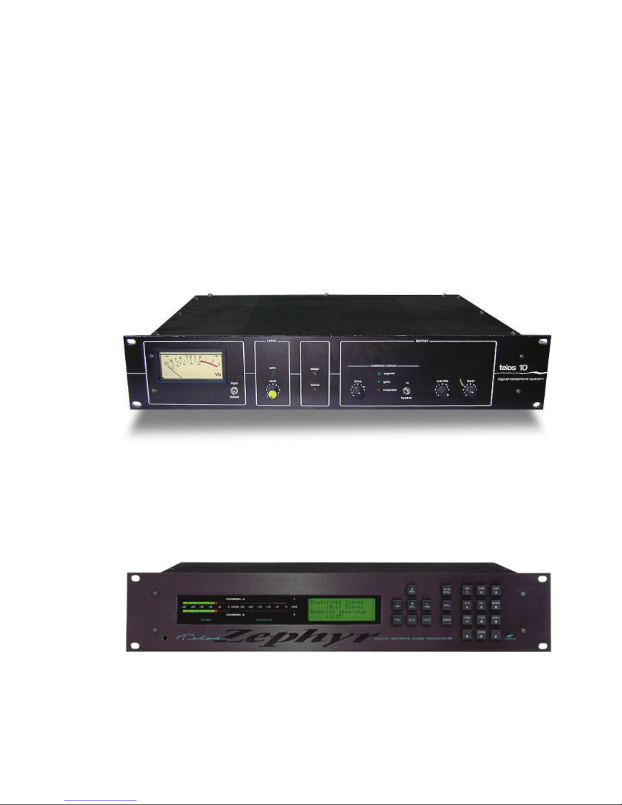
For over 30 years, Telos has led the industry in telephony and audio encoding technology for broadcast. When
Steve Church developed the first digital telephone hybrid for broadcast in 1984, it was the beginning of a revolution
in how the industry would get audio from the field on the air. Telephone calls had never sounded so good.
MP3 and ISDN
This revolution continued with the introduction of the Telos Zephyr ISDN codec in 1993. It was the first codec to
make use of the (then relatively new) MPEG Layer III codec to send full 20 kHz mono audio across a single 56 or 64
kbps data channel. Broadcasters could finally bring full fidelity audio to their listeners from the field (or between
facilities) without dedicated equalized program loops or RF links. The Zephyr quickly became the de-facto
industry standard for ISDN codecs, used by studios around the globe for transporting audio.
Page 11
SO WHAT IS Z/IPSTREAM R/2?
Streaming…It begins.
While ISDN was becoming popular for broadcasters to transport audio from the field or between facilities, the next
frontier was exploring new methods for getting audio to the listeners. The Internet was still in its infancy, but it had
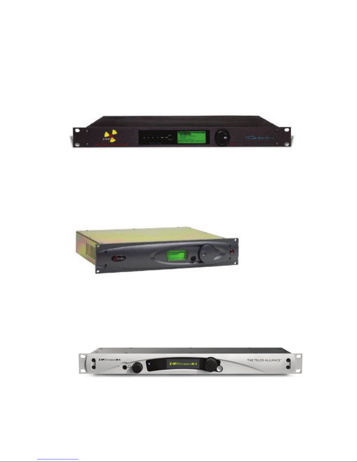
developed to the point where streaming audio (even over dialup) was becoming viable. In 1997, Telos introduced
the very first dedicated hardware encoder for MP3 streaming over the Internet, simplifying what was a bit of a
cumbersome process and dramatically improving the audio quality.
Omnia: A Legend in Audio Processing for Broadcast
SECTION 1
| 2
During this same period of time, Frank Foti was working tirelessly to improve the sound of audio processing
for broadcast. His dial-dominating innovations in audio processing at Z100 were the foundation of what would
ultimately become Omnia. The audio processing developments didn’t stop at the FM dial, however…It quickly
became apparent that there was considerable benefit to be gained from specialized audio processing for streaming
as well.
Telos Encoding + Omnia Processing = Z/IPStream
As streaming continued to gain in popularity, the demand for an “all in one” solution to handle both processing and
encoding for streams grew tremendously. In 2009, Omnia launched the A/XE software package, combining the
best of Telos encoding technology with 3-band Omnia audio processing tailored specifically for streaming. In 2012,
Telos introduced R/1, a new hardware appliance designed specifically for stream processing and encoding without
a dedicated PC.
Page 12
SO WHAT IS Z/IPSTREAM R/2?
The Z/IPStream family gained yet another powerful option with the availability of acclaimed Omnia.9 processing
in 9X/2 streaming software. Z/IPStream represents the latest in encoding and audio processing developments from
The Telos Alliance, and supports a wide variety of streaming technologies including adaptive bitrate streaming for
a seamless listener experience regardless of network conditions, or listening platform.
About R/2
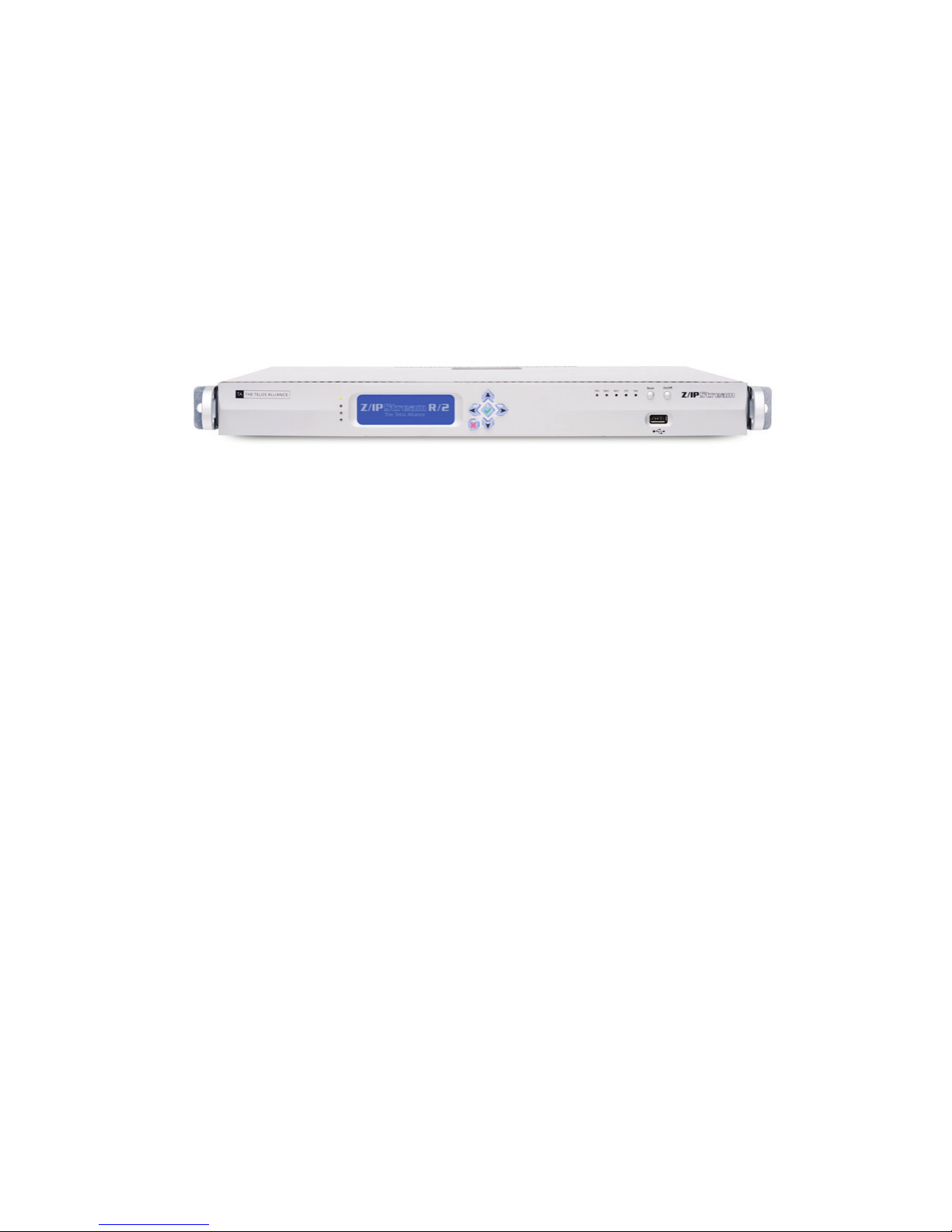
Up to 8 Channels of Z/IPStream, one box
The R/2 is a dedicated multichannel processor/encoder appliance for streaming, designed for applications
demanding the ultimate in reliability, with the highest possible audio quality and channel density per rack space.
SECTION 1
| 3
Features
Z/IPStream R/2 supports up to 8 simultaneous audio channels, including the latest generation of licensed MP3 and
AAC codecs for streaming, with signature Omnia 3-band or powerful Omnia.9 processing. Flexible configuration
allows multiple processing and/or encoding instances per audio channel.
Audio I/O includes AES/EBU, Livewire Audio over IP, and multicast or unicast RTP. Supported server platforms
include HTTP, Icecast, Shoutcast, Wowza, Adobe RTMP, and others.
Triton Digital Integration
R/2 includes direct support for the Triton Digital streaming platform, which allows users to take full advantage of
their content distribution and dynamic ad replacement technologies, while streamlining hardware and software
implementation.
Page 13
SECTION 2
| 2
2 A Few Words about Livewire+ and AES67
What is Livewire+™ ?
Livewire+ is the pioneering technology invented by the Telos Alliance to convey low-delay, high-reliability audio
over switched Ethernet.
Introduced as Livewire™ in 2003, today’s Livewire+ is AES67-compliant. That means that it complies fully with
the AES67-2013 Interoperability Standard, allowing AES67 devices to connect directly to Livewire+ networks
and exchange audio streams. Livewire+ is also extensible, able to incorporate future AES standards when they are
ratified. Livewire+ is also backward-compatible with the RAVENNA™ networking protocol.
With Livewire+, a single Ethernet cable carries real-time uncompressed digital audio, device control messages,
program associated data, and even routine network traffic. An entire facility can be wired in hours, instead of
weeks. All Axia Audio studio products, and most products from other Telos Alliance brands, utilize Livewire+
networking technology. Expanding or modifying your system is simple thanks to the inherent scalability and
modularity of Livewire+.
Livewire+ offers a revolutionary change in how studios can be built. But at the same time, it’s a natural continuation
of general trends and what you already know.
Page 14

A FEW WORDS ABOUT LIVEWIRE+ AND AES67
How Livewire+ works
Livewire+ has an audio advertising system. Every source has a text name and numeric ID. These are transmitted
from source devices to the network. Devices that play audio build lists of all available sources from which users can
select.
UsingxNode audio interfaces, you enter the names of your input sources via any PC with a web browser.
Withplayout PCs attached to the network, you open a configuration window.
Livewire+ networks employ two types of audio streams.Livestreamshave small, frequent packets optimized
for live audio that requires very low (circa1 ms.) delay, for microphones and headphone audio.Standard
Streamsare also real-time streams, but with bigger packets, and are used for audio streams which don’t require
super-low latency - like audio from CD players, or that exchanged with automation system PCs. Devices that
connect to Axia networks can transmit and receive both stream types; the user selects which type to generate when
a device is initially configured.
A sophisticated phase-locked loop clocking system allows Livewire+ to use very small buffers for least latency
and ensures that audio channels remain time-aligned (as needed for multiple mics in a studio or for TV surround-sound mixing.)
Converged Networks
SECTION 2
| 3
An Ethernet network used for Livewire+ audio can also be shared with other data transmissions, such as file
transfers and web browsing. An Ethernet system with a switch at the center may have a mix of audio nodes and
normal servers, PCs, etc., because the Ethernet switch directs traffic only to where it is needed.
Even on a single link, traffic can be mixed because we use modern Ethernet’s priority mechanism to be sure audio
packets have first call on the link’s bandwidth. A studio audio delivery system can use this capability to download
an audio file from a server, for example, while simultaneously playing another audio file live.
Livewire+ maximizes the benefits of converged networking in the broadcast facility. Many stations using Livewire+
have computer data, telephone, audio, and control on a single network that uses computer industry standard
wiring, spurring cost-efficiencies throughout the plant.
Audio Quality
A Livewire+ network is a controlled, high-speed environment, with no risk of audio drop-outs from network
problems and plenty of bandwidth for many channels of high-quality uncompressed audio. We use studio-grade
48kHz/24-bit PCM encoding. Axia digital xNode audio adapters deliver 138dB of dynamic range, with less than
0.0002% THD. Even analog xNodes have 100dB dynamic range, < 0.005% THD, and headroom to +24dBu.
Livewire+ is standards-based
Since the very beginning, The Telos Alliance has based its AoIP networking technologies on standards. IP (Internet
Protocol), the networking standard that is the underpinning of nearly all critical business networks (and of the
Internet itself ) is the basis for Livewire+ AoIP.
As charter members of the AES X.192 Working Group, we helped define the AES67 standard — and became the
first broadcast manufacturer to become AES67 compliant.
Livewire+ is so standards-based, in fact, that your audio can even be played by PC media playersthat support
standard protocols and uncompressed PCM audio. The Internet’s IP standard for streaming media, called RTP/IP,
is used for standard audio streams. RTP stands for Real-Time Protocol. It’s the Internet’s standard way to transport
streaming audio and video, just as TCP/IP is the standard for general data.
Page 15
A FEW WORDS ABOUT LIVEWIRE+ AND AES67
The Gold Standard
In the decade since the introduction of Livewire+, broadcasters have adopted it at an exponential rate; AoIP has
become the new standard for broadcast facilities.
SECTION 2
| 4
Consider these facts:
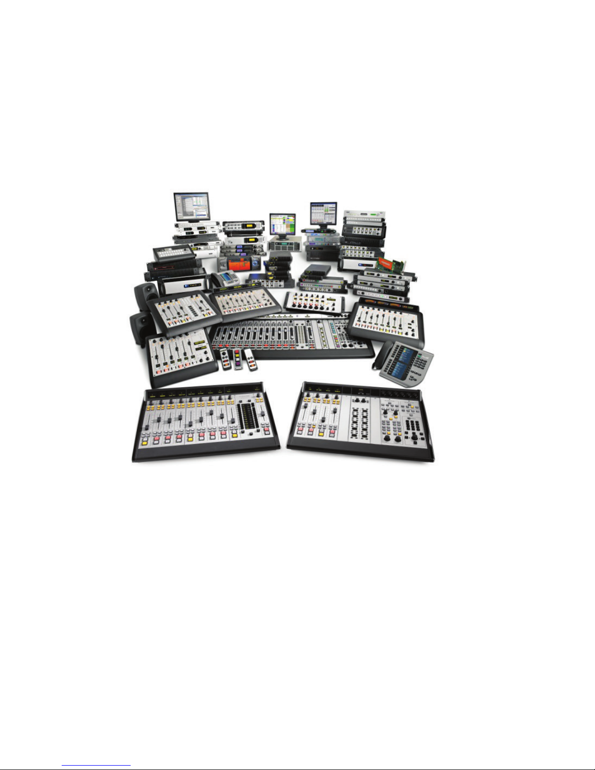
♦ There are over 6,000 studios worldwide built with Livewire+.
♦ More than 5,500 networked Axia consoles are at work daily.
♦ Over 80 Livewire+ Partner companies provide compatible hardware and software products.
♦ There are more than 60,000 individual Livewire+ devices in the field.
♦ Livewire+ is fully compliant with the AES67 Interoperability Standard.
Impressive, no? But there are even more exciting things in the future. The Telos Alliance, with one of the largest
R&D groups in broadcast, is fully committed to AoIP interoperability. We’ve been proponents of open standards
since Day 1, freely sharing our technology with interested Hardware and Software Partners. We were charter,
supporting member of the X.192 Working Group that defined the AES67 standard, and as founding members
of the Media Networking Allliance, are actively engaged in work to promote and enhance standards-based AoIP
networking.
Page 16
3 Installation
Physical Considerations
Rack Mounting
R/2 includes a pair of rack rails designed to secure the unit to the rear of the equipment rack. It is highly recommended that you install these rails if possible due to the depth of the unit. Mounting by the front panel alone
may cause excessive strain on the chassis and is not recommended. The supplied rails should fit in most standard
equipment racks, but if installing the rails is not possible, you may wish to consider placing an upside-down rack
shelf underneath the unit for additional physical support.
Airow
As with most rackmount server chassis, the airflow on R/2 is from front to back. While it is not absolutely necessary to leave an additional rack space above and below the unit, it certainly is not a bad idea if the space is available.
Do not block the front panel of R/2 behind a solid rack door.
SECTION 3
| 5
Wiring Management
Since airflow is from front to back, it is important to keep the rear of the unit free from obstructions to allow for hot
air exhaust. Install the wiring in such a way that it allows for a reasonable service loop and does not block airflow.
Do not allow wiring from other equipment in the rack to block airflow from the rear panel of R/2.
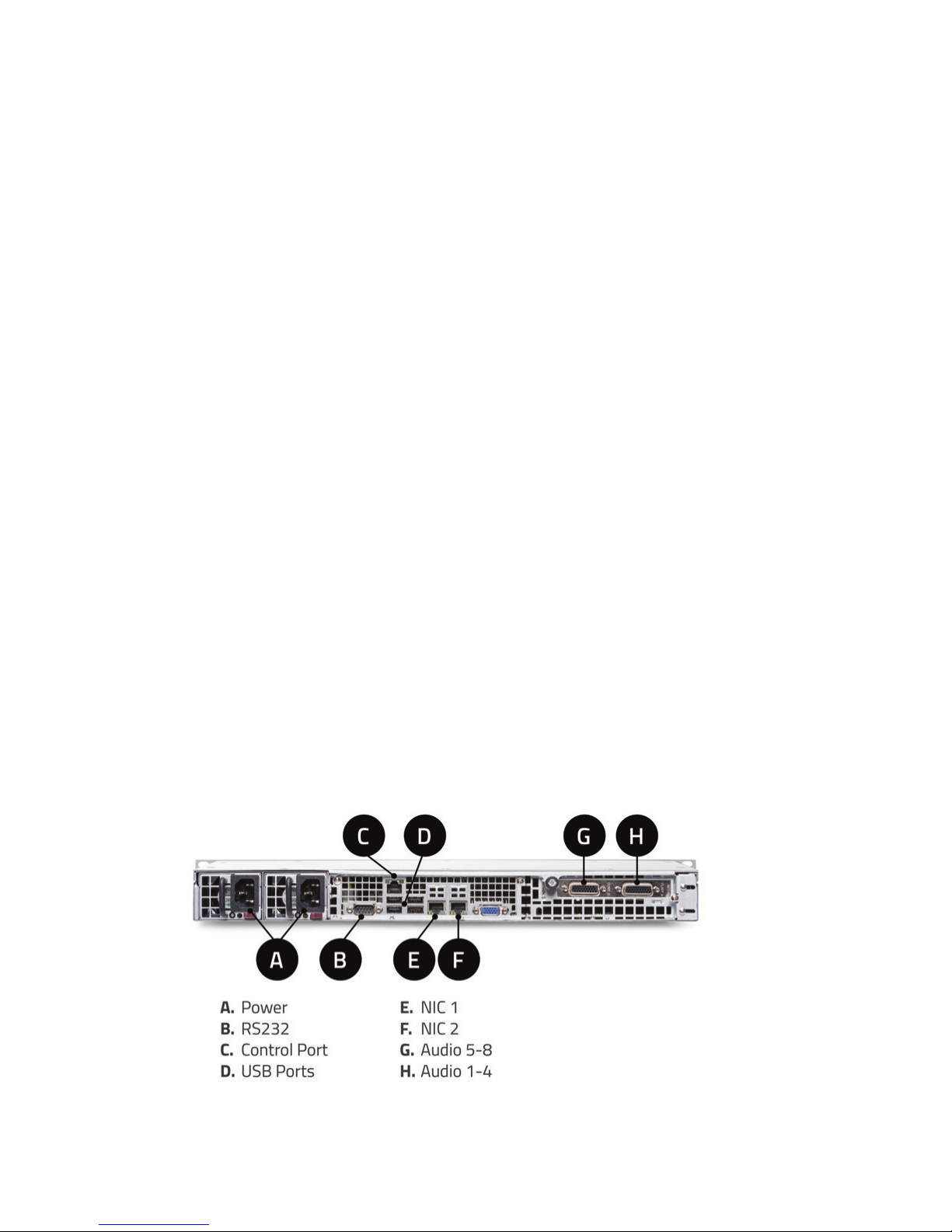
Rear Panel
Page 17

INSTALLATION
Power
The R/2 is equipped with dual power supplies (120V – 240V, 50 – 60Hz) to allow for facilities with redundant
power feeds to the equipment racks from separate sources. An LED on the supply will indicate the presence of AC
power and proper operation. If power is lost on one of the AC inputs or one of the supplies should fail, the R/2
will sound an alarm. The only way to mute this alarm is to connect power to both supplies or (in the case of power
supply failure) remove the failed supply.
RS-232
Not currently implemented. Inserting stream metadata via RS-232 will be supported in a future release. See chapter
10 (Metadata Sources and Filters) for more details about stream metadata.
“Control” Ethernet Port
SECTION 3
Note:
If only one of the two power supplies is connected, an alarm will sound. Connect both supplies to
AC power, even if you don’t have redundant AC power feeds to the equipment rack.
| 6
This port (if populated) is intended for out-of-band system management. Not currently implemented.
USB Ports
Future expansion or factory service. Not currently implemented.
NIC 1 and NIC 2
The R/2 offers dual network adapters. Typically, one adapter (NIC1) would be used for Audio over IP, while the
second (NIC2) would be dedicated to streaming audio traffic. Either interface can be used for management via the
web GUI. Connect your network(s) to NIC 1 and/or NIC 2. Do not connect both interfaces to the same network.
Doing so may cause routing and connectivity issues.
Note:
Do not connect both interfaces to the same network simultaneously. Routing and connectivity
issues may result. Ensure each interface is connected to a dierent IP network, (dierent VLAN,
physical switch, IP address block, etc.) as necessary. Consult your IT department or Telos technical
support if you are not sure how the interfaces should be congured. Only one interface may be
needed in some rare cases.
Page 18
INSTALLATION
VGA
Factory service only. Not currently implemented.
Audio (AES/EBU)
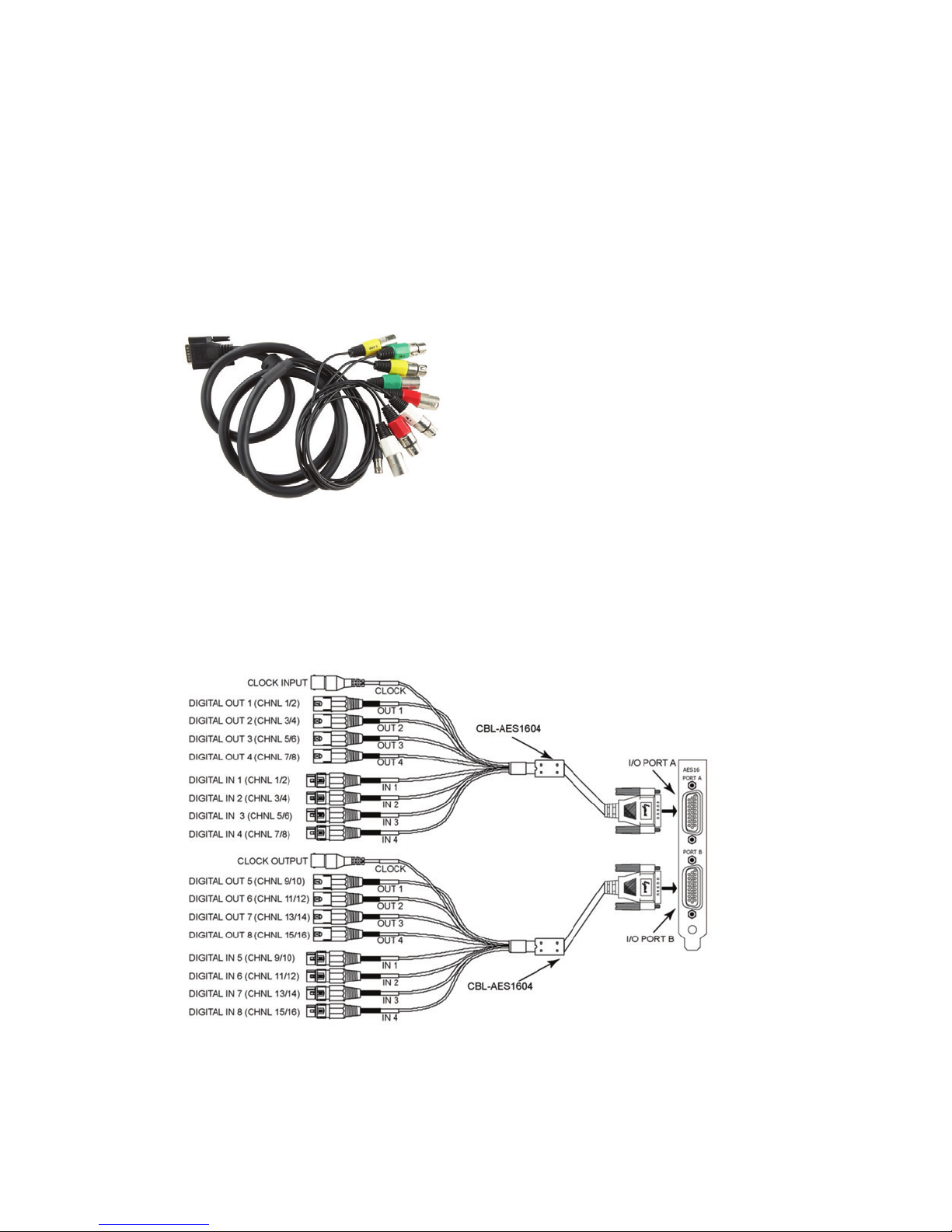
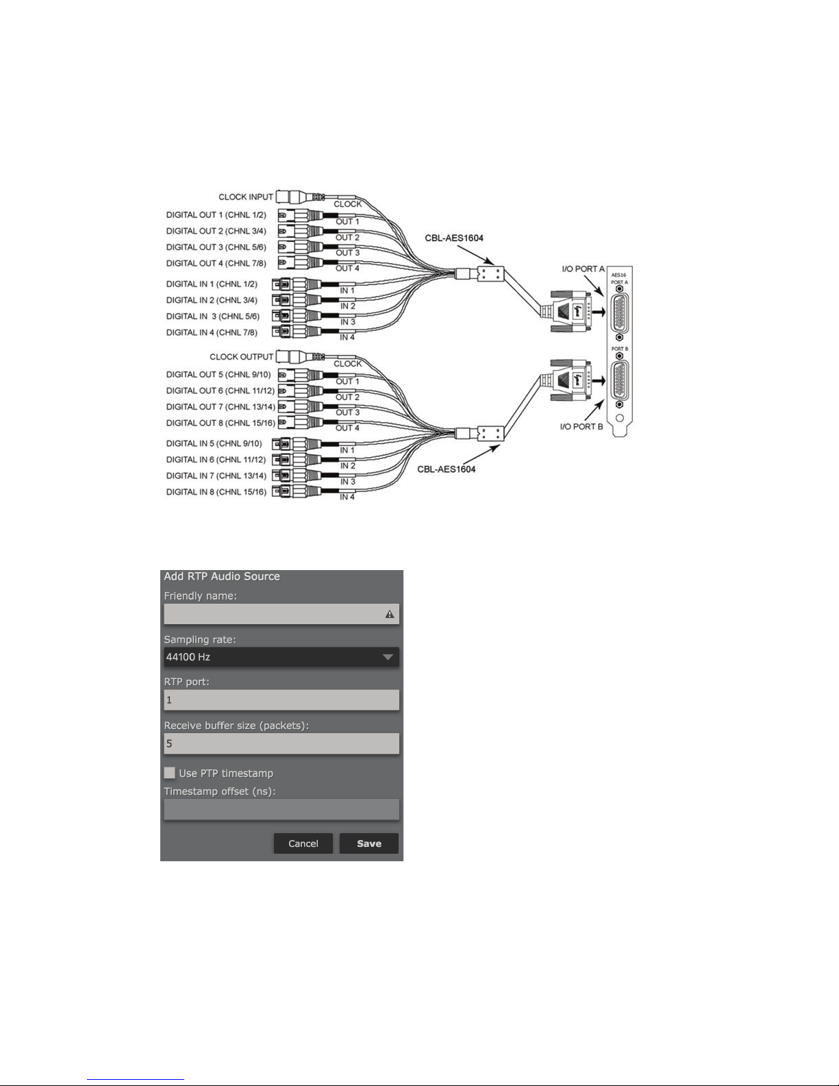
Eight AES/EBU audio connections are available through two high-density 26-pin D-sub connectors. Connect the
provided breakout cable(s) to the D-sub connectors. Use the thumbscrews to securely attach the cables in place.
Sample rate conversion is provided on all inputs. The BNC Word Clock connectors are not currently implemented. Each audio channel can be configured to generate a stream at 44.1 or 48 kHz (see Chapter 7: Audio Source
Configuration).
SECTION 3
| 7
AES Breakout Cable Layout
Page 19

INSTALLATION
Audio Card Pinout
Port A, Jumpers
Pin Signal Pin Signal Pin Signal
1 Clock Gnd 10 Clock In
2 OUT4 Cold 11 OUT4 Hot 19 OUT4 Gnd
3 OUT3 Gnd 12 OUT3 Cold 20 OUT3 Hot
4 OUT2 Cold 13 OUT2 Hot 21 OUT2 Gnd
5 OUT1 Gnd 14 OUT1 Cold 22 OUT1 Hot
6 IN4 Cold 15 IN4 Hot 23 IN4 Gnd
7 IN3 Gnd 16 IN3 Cold 24 IN3 Hot
8 IN2 Cold 17 IN2 Hot 25 IN2 Gnd
9 IN1 Gnd 18 IN1 Cold 26 IN1 Hot
SECTION 3
| 8
Port B, Jumpers
1 Clock Gnd 10 Clock Out
2 OUT8 Cold 11 OUT8 Hot 19 OUT8 Gnd
3 OUT7 Gnd 12 OUT7 Cold 20 OUT7 Hot
4 OUT6 Cold 13 OUT6 Hot 21 OUT6 Gnd
5 OUT5 Gnd 14 OUT5 Cold 22 OUT5 Hot
6 IN8 Cold 15 IN8 Hot 23 IN8 Gnd
7 IN7 Gnd 16 IN7 Cold 24 IN7 Hot
8 IN6 Cold 17 IN6 Hot 25 IN6 Gnd
9 IN5 Gnd 18 IN5 Cold 26 IN5 Hot
Power Up
Press the “On/Off” button located on the right half of the front panel to power up the unit (See Chapter 4 for a full
front panel description). During the power up process, the front panel will light up and display a splash screen. If
the display remains dark and fans do not spin up, verify that AC power is present at both power supply inputs.
Pin Signal Pin Signal Pin Signal
If the fans spin up but the display remains dark or does not show a splash screen, contact support.
Page 20

INSTALLATION
Fans
The fans in R/2 are thermostatically controlled. As the unit powers up, the fans will start at full speed. They should
spin down to a much slower speed after a short period of time. If they do not return to low speed, it may indicate a
faulty fan or other hardware issue. During normal operation, these fans may increase in speed if the unit’s internal
temperature rises. If the fans remain at full speed during operation and the environmental temperature of the unit
appears normal, contact support.
Input Level Meters
SECTION 3
| 9
Note:
The fans will run at full speed for a brief period of time during boot. They should return to a relatively
moderate speed within a short period of time. If the fans remain at full speed, it may indicate a
hardware fault. Slightly higher fan speed during operation is normal if the internal temperature of
the unit increases.
Once the unit has fully booted, the front panel LCD will display the input audio level meter screen. As of software
version 1.0.34, these meters can display either AES or Livewire input levels by using the up and down navigation
arrows on the front panel.
Livewire and other Audio over IP input sources (as well as output level metering and processing metering) can
also be metered via the unit’s web GUI or via NfRemote for Omnia.9 processing (See Chapter 16 for Omnia.9
processing information).
Note:
Select between Livewire or AES input levels by using the up and down navigation arrows from this
screen (see chapter 7 for information about dening audio sources). Metering can also be accessed
from within the web GUI or NfRemote software (if using Omnia.9 processing).
Page 21
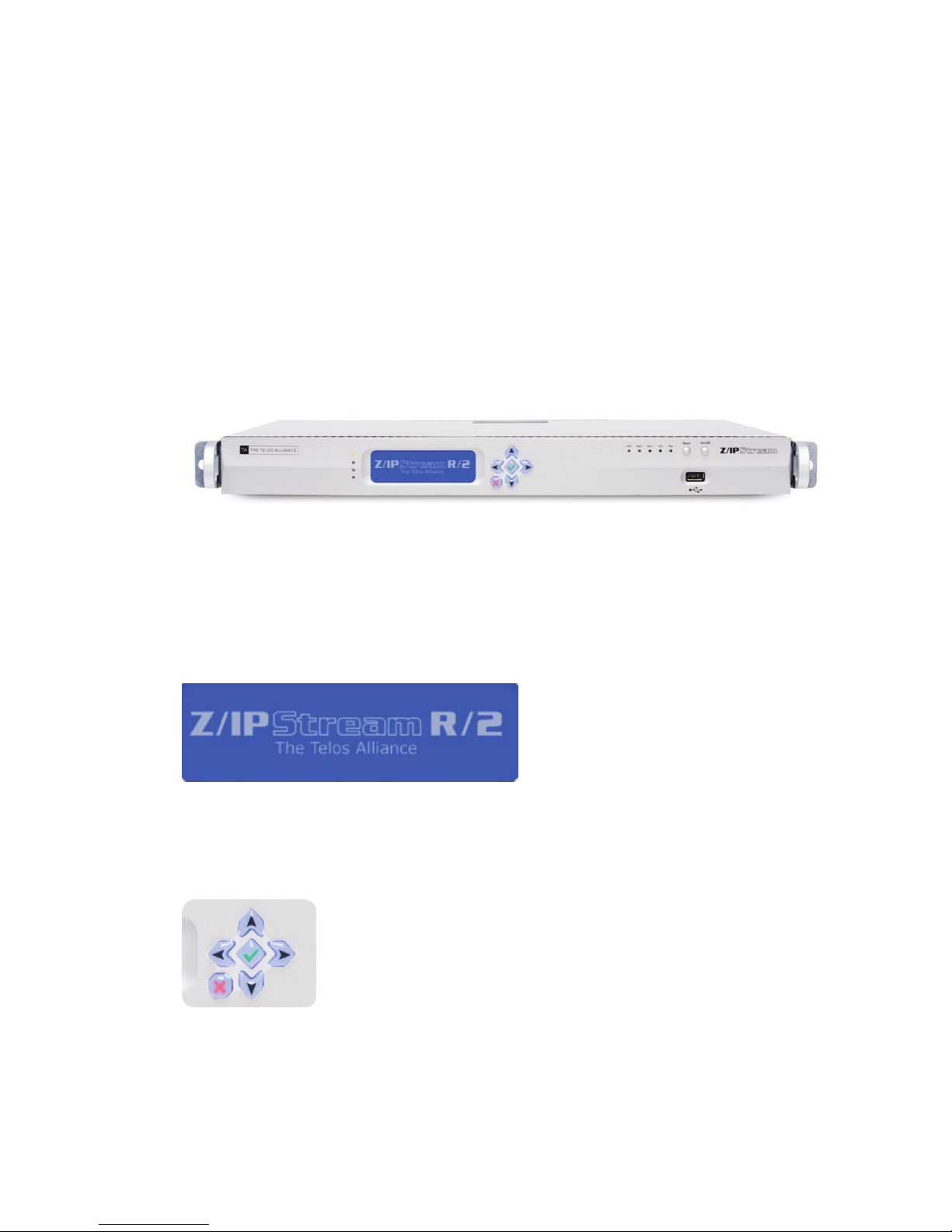
4 Front Panel Interface
Overview
This chapter describes the front panel controls and indicators of R/2.
Status LEDs
A column of four LEDs is located directly to the left of the main LCD. The top LED illuminates when the system is
operating. The others are not currently implemented.
SECTION 4
| 10
Main LCD
The main LCD provides unit status and configuration. If this LCD fails to display the Z/IPStream R/2 splash screen
at startup, or remains blank during operation, please contact technical support.
Navigation Cluster
A six button navigation cluster is used for initial IP address configuration and navigating the front panel LCD.
The controls are relatively self explanatory. Up and down will increment or decrement values, or scroll between
parameter settings. Left and right will move between digits in IP address entry, or move between screens on the
front panel. The red “X” button will cancel an entry, the green “” (OK button) will confirm the current setting or
select a parameter for modification.
Page 22

FRONT PANEL INTERFACE
System Status LEDs
A set of five LEDs next to the power and reset buttons indicates system status.
Info
Used for alert indication or system identification.
♦ Solid red: The system has overheated. This may be caused by reduced airflow or high ambient tempera-
ture in the rack. Ensure there is nothing obstructing the front or back of the unit and that the temperature
in the rack is normal.
♦ Blinking red (1 second intervals): Fan failure. Contact technical support.
♦ Blinking red (1/4 second intervals): Power supply failure. Check for a failed power supply, contact
technical support.
♦ Blue (solid or blinking): Local or remote Unit ID function—Not currently implemented.
Net 2
Indicates NIC 2 link and activity. Flashes during activity. This LED will remain dark if NIC 2 is not connected.
SECTION 4
| 11
Net 1
Indicates NIC 1 link and activity. Flashes during activity. This LED will remain dark if NIC 1 is not connected.
SSD
Indicates activity of the internal Solid State Drive. Flashes intermittently during normal operation.
Pwr
This is the main system power LED and will illuminate whenever the system is powered up.
System Controls
Reset
Performs a “hard” reset on R/2 to reboot. Should not be used during normal operation, but can be used if the R/2
becomes unresponsive for some reason. Should this occur, contact technical support.
On/O
Performs an orderly power up or shut down. A slight delay before shut down after pressing this button is normal.
The SSD indicator will flash rapidly for a short period of time during shut down.
Page 23

FRONT PANEL INTERFACE
Front Panel USB Port
This port is used for software upgrades, as well as factory configuration and troubleshooting. Contact technical
support for additional information.
SECTION 4
| 12
Page 24
5 IP Address Conguration
Overview
After physical installation of R/2 has been completed, at least one of the two network interfaces must be assigned
an IP address to allow further configuration and normal operation.
IP Conguration
Each of the two network interfaces on R/2 can be assigned a static IP address, or obtain an IP address automatically
via DHCP (Dynamic Host Configuration Protocol). In most applications, R/2 would be assigned static IP addresses, but it may also be helpful to use DHCP with reserved assignments tied to the MAC addresses of R/2. Contact
your network administrator if you are unsure of what your network requires.
Metering Screen
SECTION 5
| 13
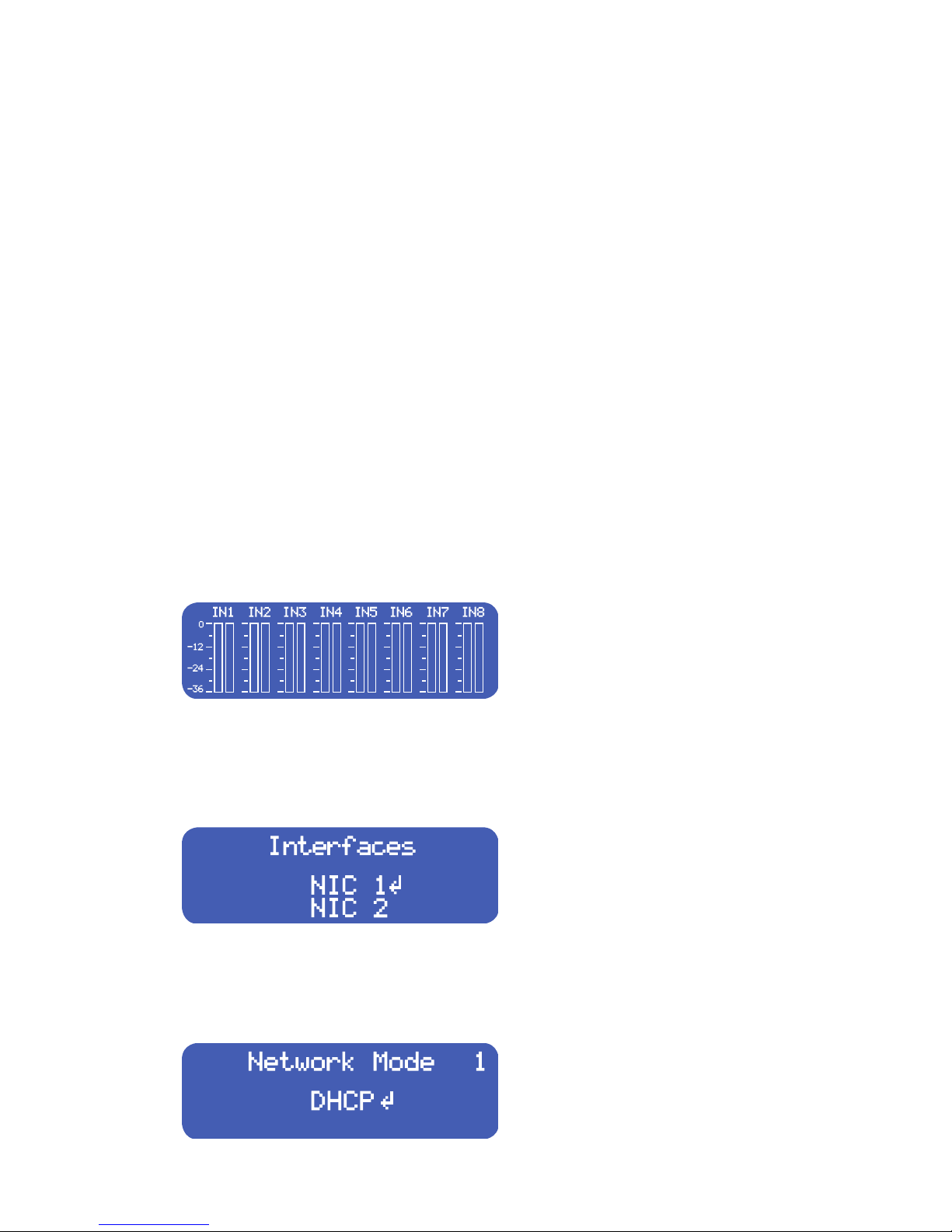
After the unit boots, it should be displaying the audio input level metering screen. This is the normal “home”
condition for the R/2 display. The up/down arrows will select between AES and Livewire input levels (see Chapter
7). “X” or the left/right arrows will allow you to return to this point from other areas of the front panel screens.
NIC Selection
From the metering screen, use the right arrow to move to the “Interfaces” screen. Select “NIC 1” or “NIC 2” by
using the up/down arrow keys. The display arrow will move to indicate the current selection. Press the “” key to
select the desired interface.
Network Mode
Page 25
IP ADDRESS CONFIGURATION
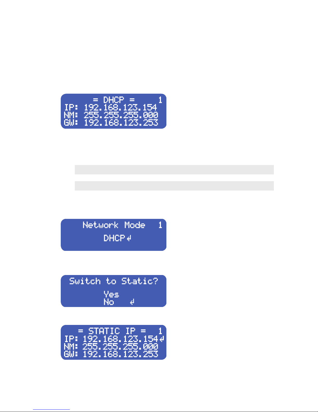
Once you have selected the desired interface (displayed here in the upper right hand corner of the LCD), you can
select which mode that interface should operate in. By default, R/2 ships with both interfaces configured for DHCP.
Verify Current Interface Parameters
To verify the current IP address and mode, from the “Network Mode” screen, press the right arrow. In the example
above, NIC 1 is set for DHCP and has an address of 192.168.123.154 with a subnet mask of 255.255.255.0 and a
gateway of 192.168.123.253. Press the left arrow or “X” to return to the “Network Mode” screen.
Note:
If the network cable is not connected to an interface, one of two conditions may occur…A “self-assigned” IP address of 169.x.x.x or all zeros (even if a static IP has been assigned). This may also occur
if the unit is congured for DHCP but not able to reach a DHCP server.
SECTION 5
| 14
Conguring a Static IP
From the “Network Mode” screen, press the “” key. You will be asked to switch to static mode. Note the interface
number displayed in the upper-right hand corner (NIC 1 in this example).
Use the up arrow key to select “Yes”, then press the “” key. The “Static IP” configuration screen will be displayed.
Page 26
IP ADDRESS CONFIGURATION
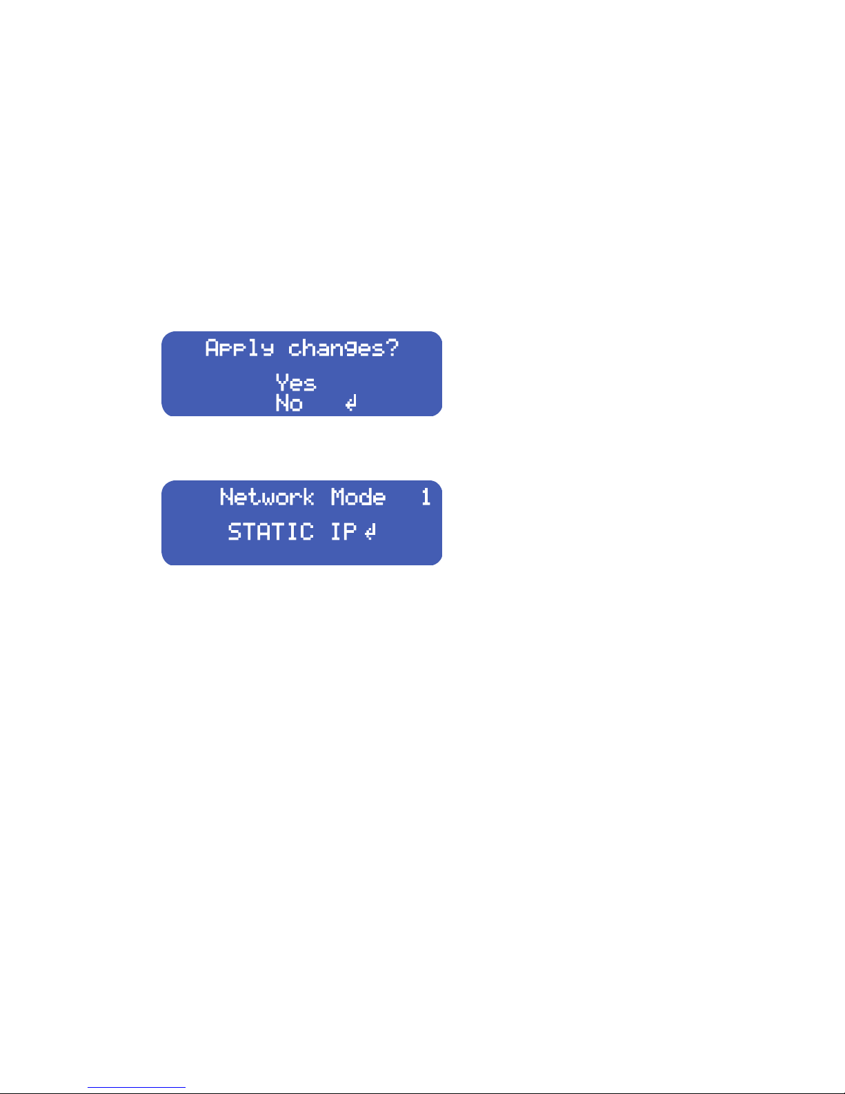
To modify the static IP configuration:
♦ Use the up/down arrow keys to select the field you want to change (IP address, Netmask, or Gateway).
♦ Press the “” key to begin editing a field.
♦ While editing a field, use the left/right arrow keys to select the digit you wish to change, then the up/
down arrow keys to change the value.
♦ When done editing, press the “” key.
When finished entering all values, press the right arrow key. The display will prompt: “Apply Changes?”
Use the up arrow key to select Yes, then press the “” key to select. After a few moments, you will be returned to the
“Network Mode” screen.
SECTION 5
| 15
To configure the second NIC, return to the “Interfaces” screen, select “NIC 2”, and repeat the configuration process.
Page 27
6 Web GUI Navigation
Overview
Beyond initial IP address settings from the front panel, all R/2 configuration is performed through a web browser
(or through NfRemote software for Omnia.9 processing—See Chapter 16). This chapter will provide an overview
of the R/2 web GUI.
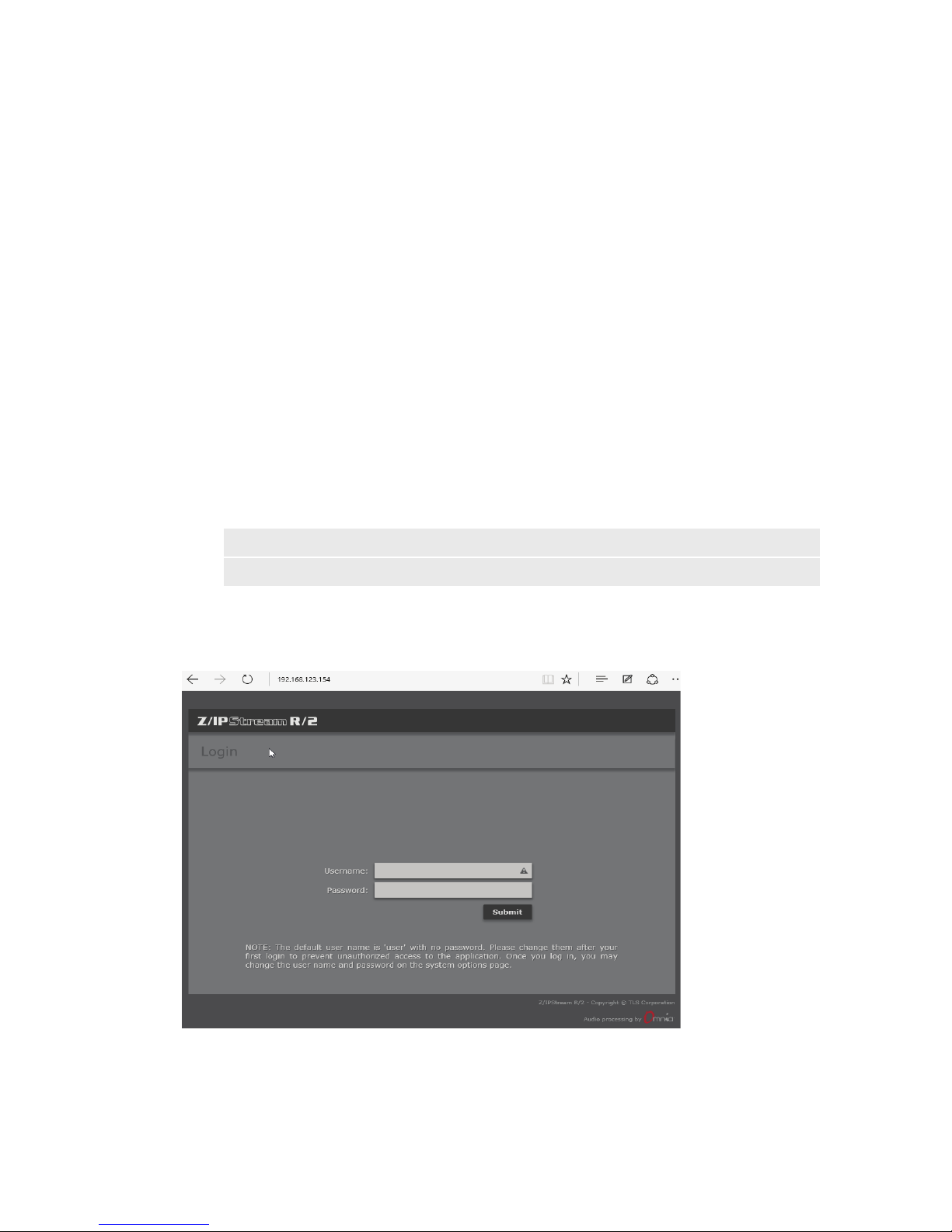
On a computer with access to the same network as R/2, enter the R/2’s IP address (configured from the front panel
in the previous chapter) in a web browser. The unit can also be located by the hostname: R2-XXXXXX, replacing
XXXXXX with the serial number of the unit. For example, unit 74-1001 will be R2-741001.
Note:
Most modern browsers are supported (including Chrome, Firefox, Safari, Edge, and others that
support HTML 5). No Java or Flash is used in the R/2 web GUI.
SECTION 6
| 16
Login
Enter user as the user name. There is no default password. click the Submit button. You should now be logged into
Z/IPStream R/2.
Page 28
WEB GUI NAVIGATION
Control Panel
SECTION 6
| 17
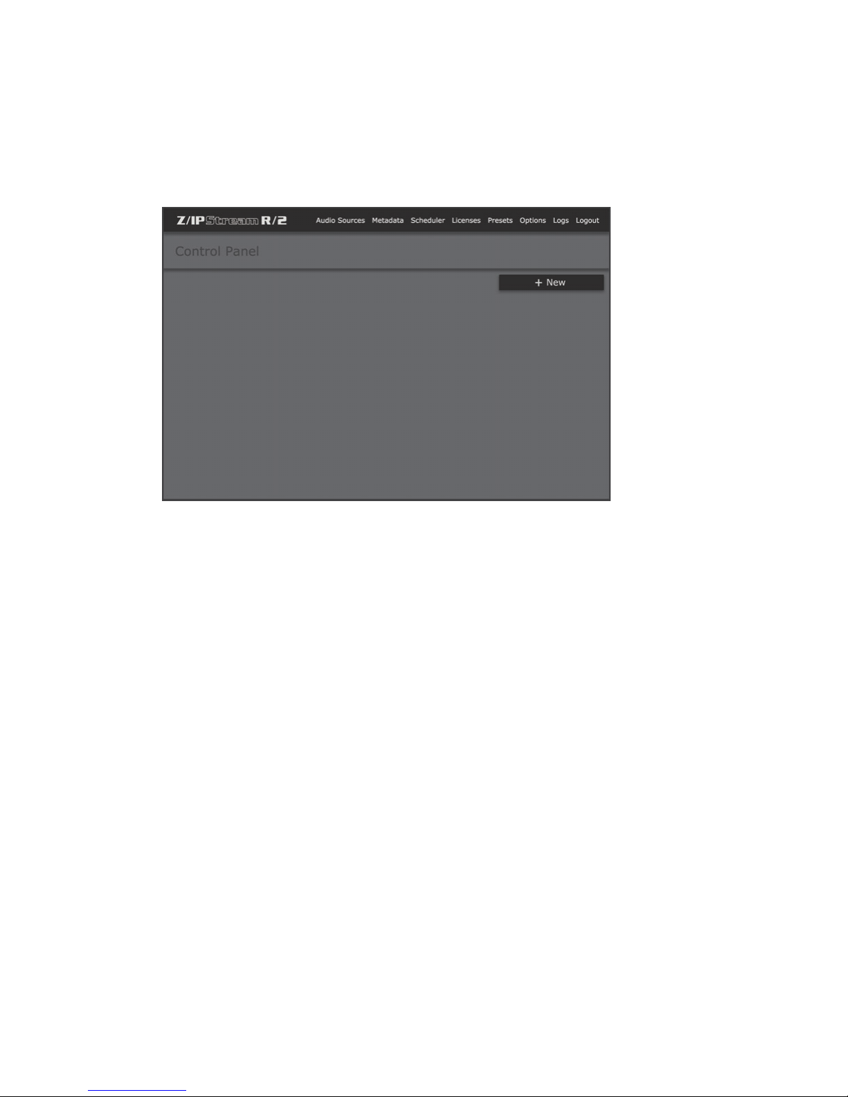
The main “home” display is called the “Control Panel” This is the screen where the status of all processing and
encoding instances is displayed, and new processing or encoding instances are defined (Chapter 8). All other
configuration functions can be accessed through the sections listed at the top this screen. Click the “Z/IPStream
R/2” logo at the upper left corner or “Main” to return here at any time. “Help” in sub-menus will download a copy
of this manual, and “Logout” will return to the login screen.
Page 29
WEB GUI NAVIGATION
Audio Sources (Chapter 7)
SECTION 6
| 18
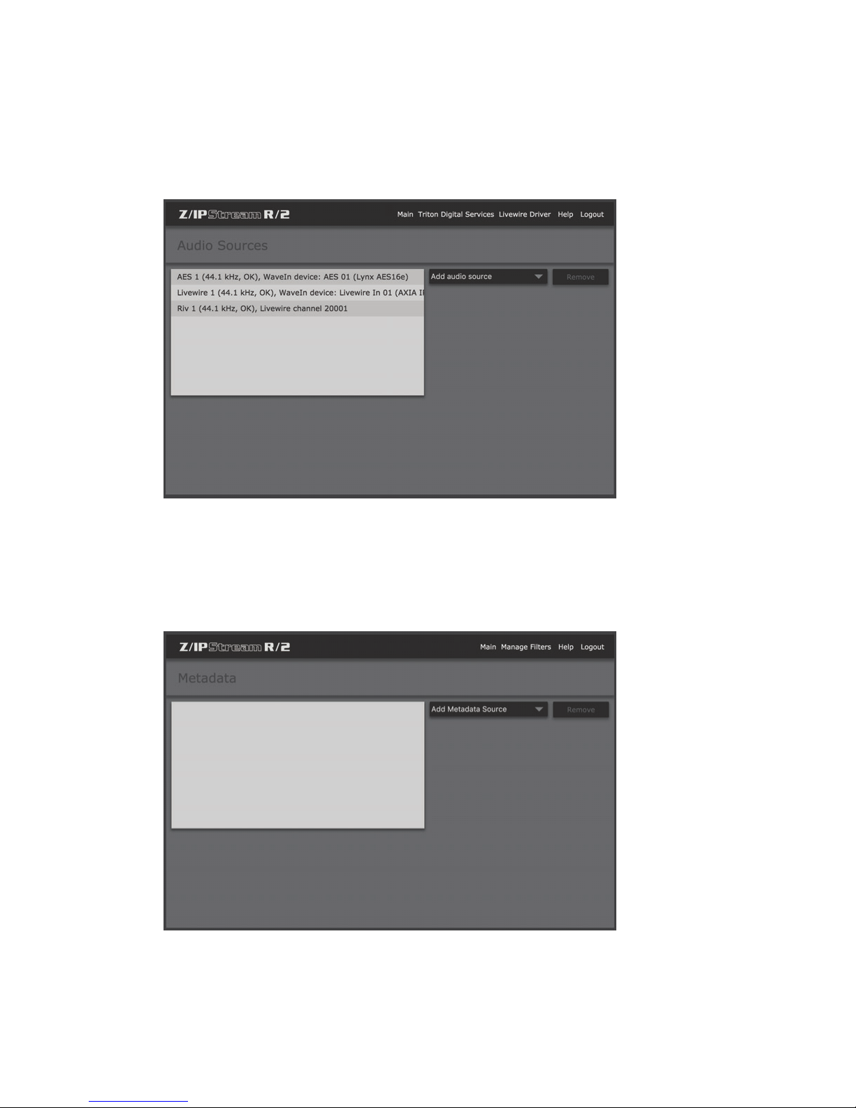
R/2 is licensed by number of audio sources. These sources must be defined before processing and encoding instances can be configured. The “Audio Sources” screen defines available audio channels for processing and encoding.
These sources can be AES inputs from the internal audio card, Livewire channels from an Audio over IP network, or
other RTP audio stream (Unicast or Multicast).
Metadata (Chapter 10)
Web streams frequently have “Now Playing” metadata associated with them for display on websites and other
streaming clients. The “Metadata” section of the interface is where these metadata sources are defined. Incoming
data via TCP, UDP, is supported. RS-232 will be supported in a future version. Custom XML “Metadata Filters”
allow considerable flexibility in data formatting and translation.
Page 30
WEB GUI NAVIGATION
Schedule Manager (Chapter 11)
SECTION 6
| 19
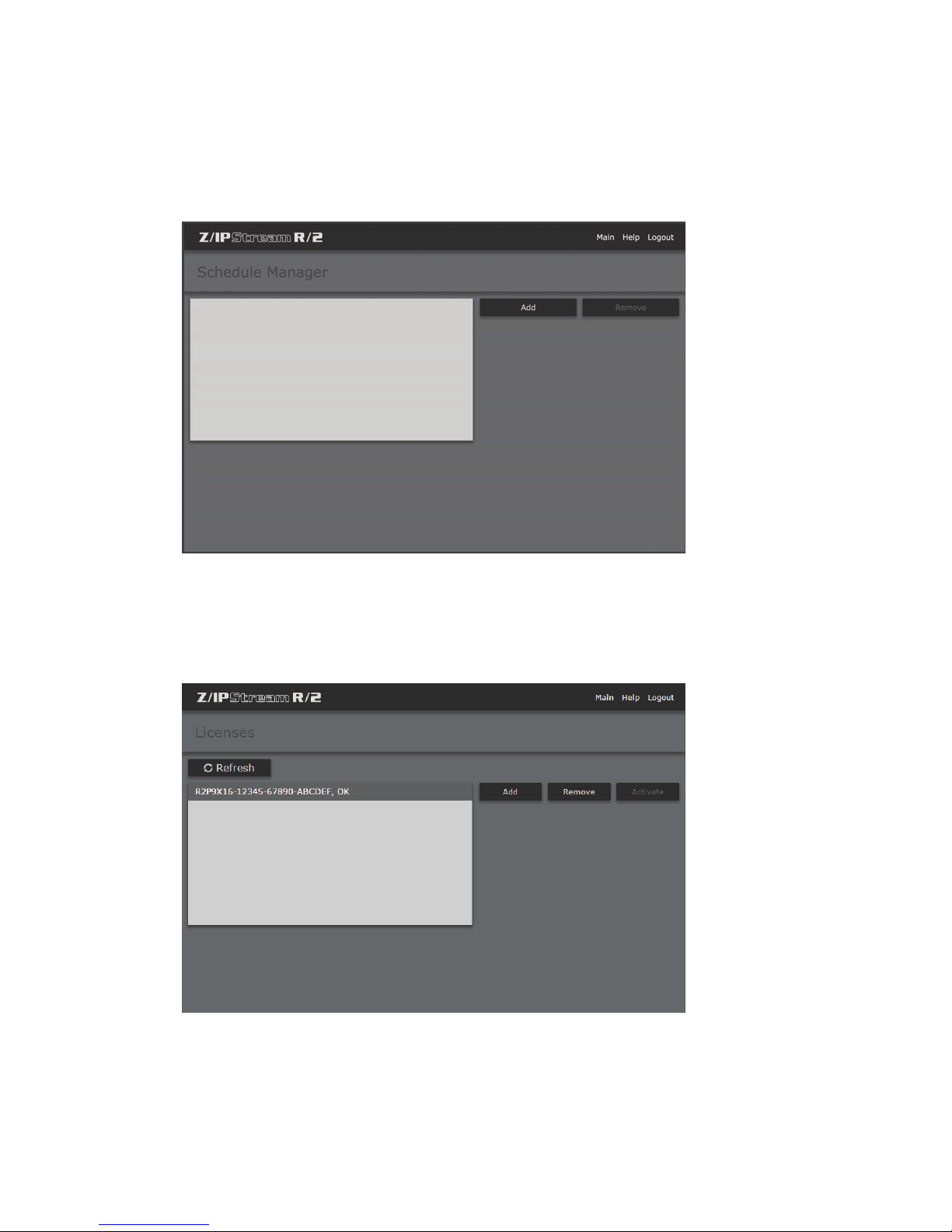
R/2 supports timed scripting of events for various functions. This could include switching to an alternate audio
source on a stream, changing a processing preset, or blacking out a sports broadcast or other content for which you
do not have streaming rights.
Licenses (Chapter 12)
R/2 is a modular platform which can be licensed for various numbers of channels (from 2 up to 8) and types of audio
processing (Omnia 3-band or Omnia.9). This screen allows management of the licenses available on the system.
Page 31
WEB GUI NAVIGATION
Processing Presets (Chapter 13)
SECTION 6
| 20
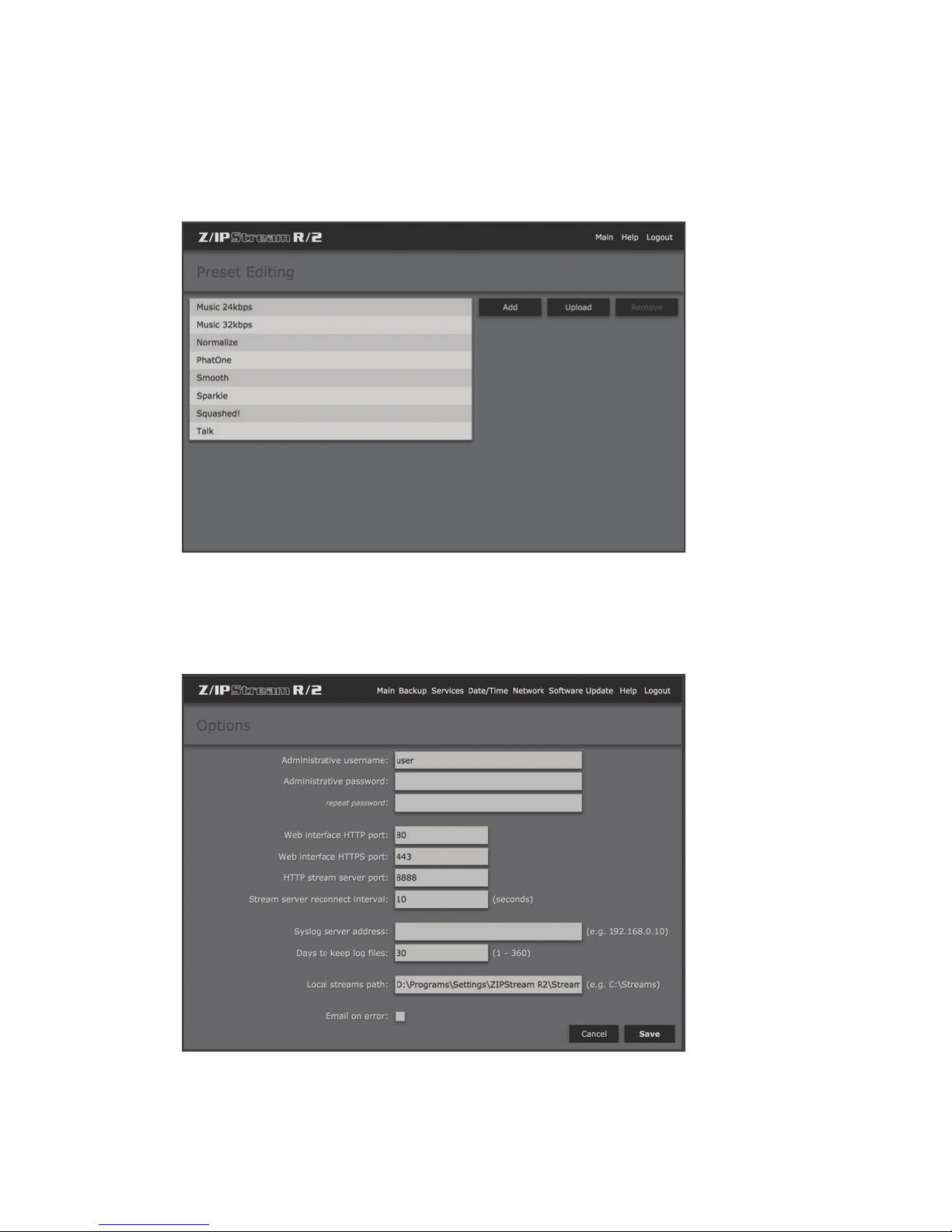
The “Preset Editing” screen allows management of audio processing presets for the standard Omnia 3 processing.
Presets can be added (copied from an existing preset), uploaded from a compatible preset file, or deleted from the
unit. Omnia.9 processing presets are managed through NfRemote software (see Chapter 16).
Options (Chapter 14)
Includes global configuration options for R/2, including management of background software services, as well as
software updates, and backup and restore of system configuration. Network parameters can also be configured
from this section.
Page 32
WEB GUI NAVIGATION
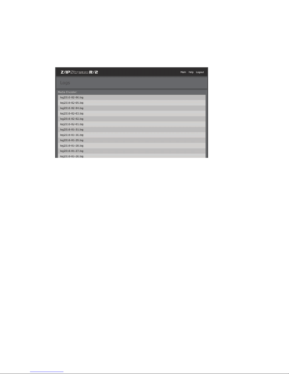
Logs (Chapter 15)
Comprehensive logs are kept for diagnostic and other purposes. This screen allows viewing or downloading logs
from R/2.
SECTION 6
| 21
Page 33
7 Audio Source Conguration
Overview
This chapter will cover defining the audio sources available for processing and encoding in R/2—one of the most
critical steps in configuration after setting the IP addresses and accessing the web GUI.
R/2 is licensed by number of audio sources. Two audio sources are standard with R/2, up to eight can be licensed
per unit. Each of these audio sources is available for multiple instances of processing and/or encoding. 3-band
Omnia processing is standard, with optional Omnia.9 processing available.
Audio Sources
SECTION 7
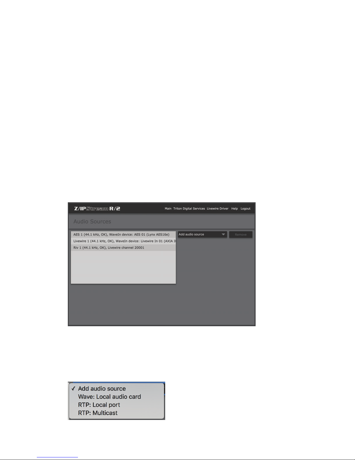
| 22
This screen will display the audio sources currently available on the system, and allow you to add new or remove
existing sources. To add a new audio source, click on “Add audio source”. To remove an existing source, select it
in the list, then click “Remove”. Ensure that the source is no longer in use by any encoding or processing instances
before removing it.
“Add Audio source” menu
Select the type of audio source you wish to add.
Page 34
AUDIO SOURCE CONFIGURATION
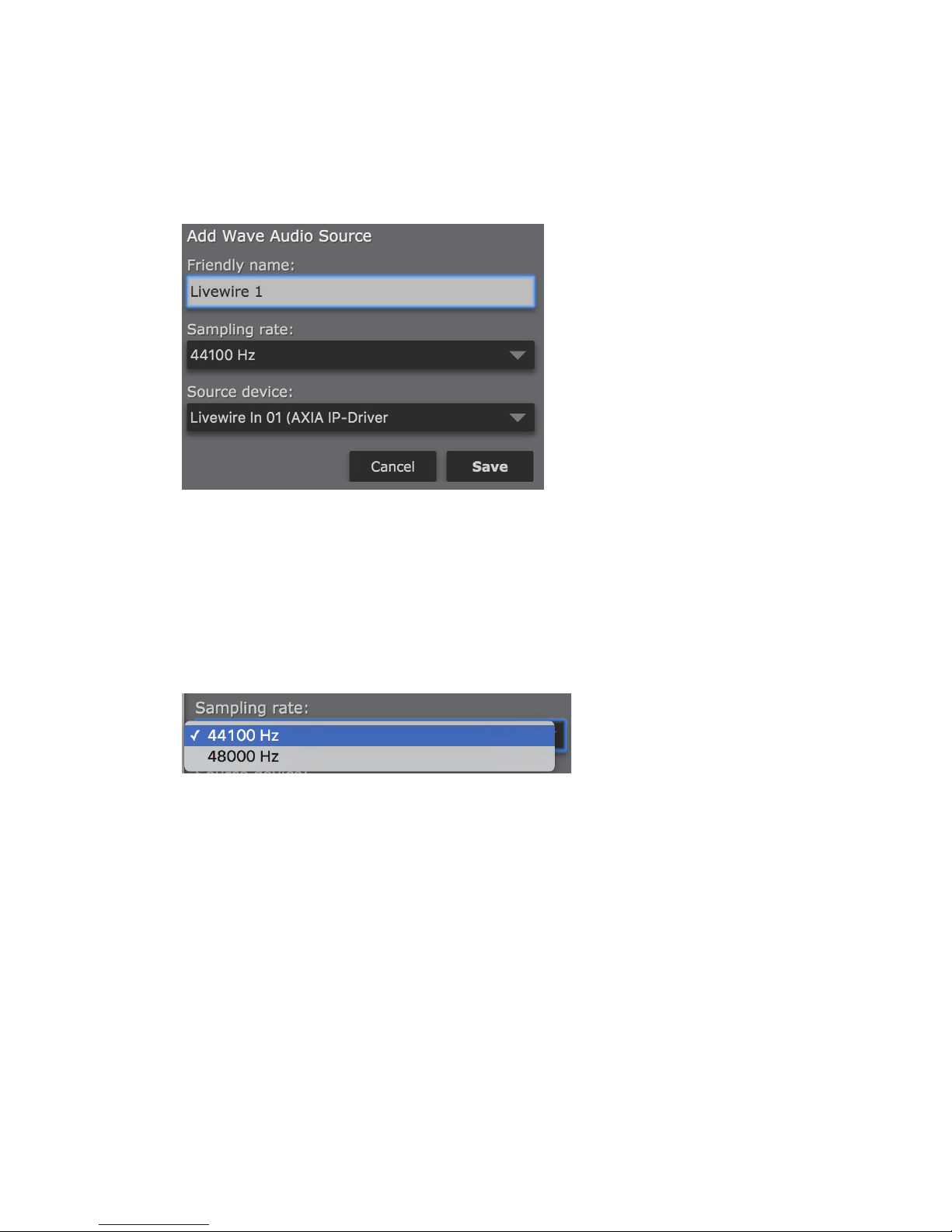
Wave: Local audio card
Allows input from a local AES/EBU audio source or Livewire audio channel. Selecting this option will open the
“Add Wave Audio Source” panel.
SECTION 7
| 23
Friendly name
Since many audio source names on the system can be very similar, give this audio source a “Friendly” name that
will be easier to remember when configuring processing and encoding instances (for example, Livewire 1, AES 1,
Classical, Jazz, or whatever else will make it easier to identify in R/2).
Sampling rate
This is the sample rate that the streams from this audio channel will be generated at. Available options are 44.1 kHz
or 48 kHz. Choose whichever sample rate best suits the streaming application.
Page 35
AUDIO SOURCE CONFIGURATION
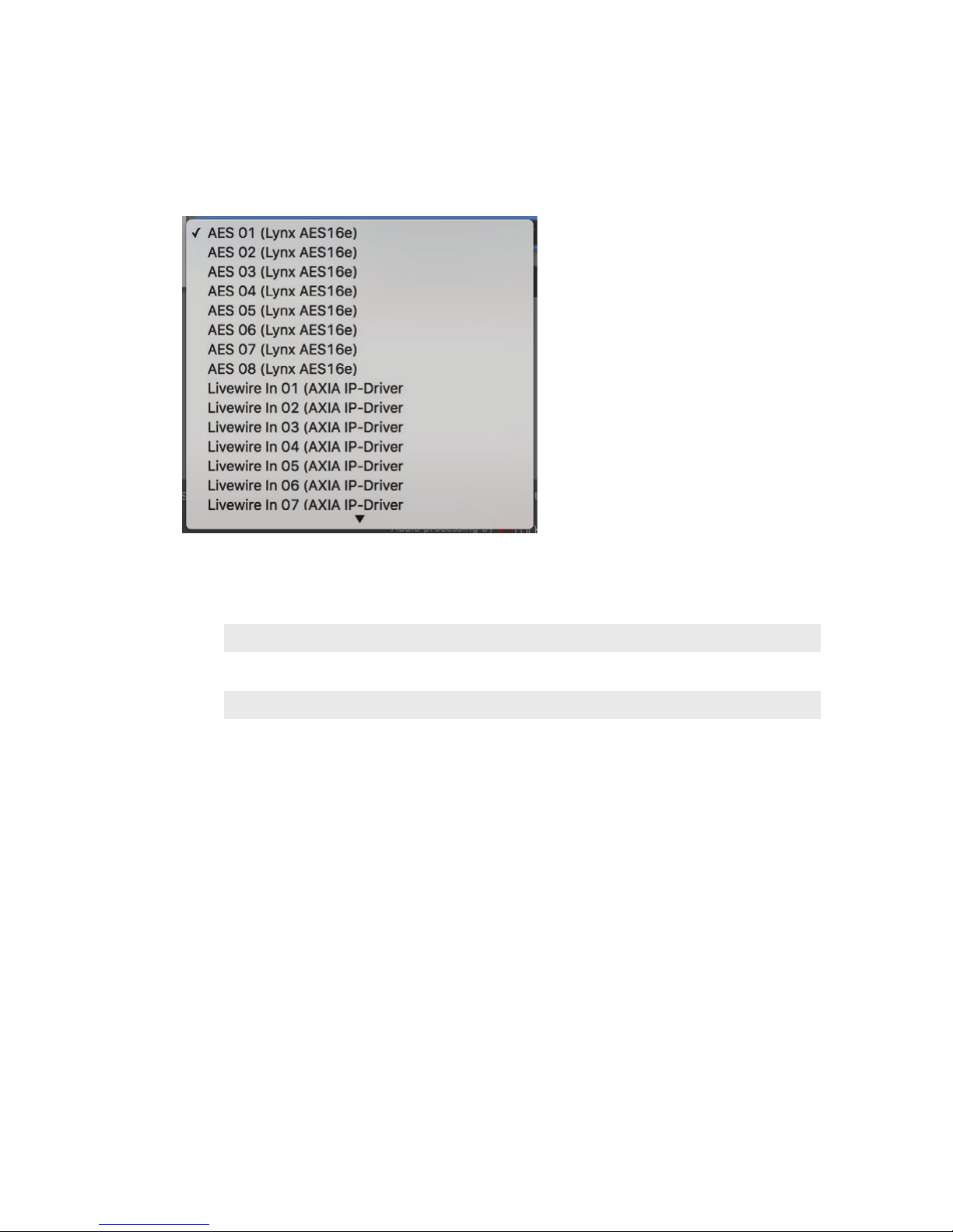
Source device
Displays a list of available source devices on the system. There are up to 24 possible Livewire inputs available
(defined via the “Livewire Driver” menu) and 8 AES inputs available.
SECTION 7
| 24
Notes:
Available Livewire I/O channels are mapped via the “Livewire Driver” menu.
Audio card port “A” carries channels 01 through 08 (In 1-4) while port “B” carries channels 09
through 16 (In 5-8).
Page 36
AUDIO SOURCE CONFIGURATION
AES Breakout Cable Layout
SECTION 7
| 25
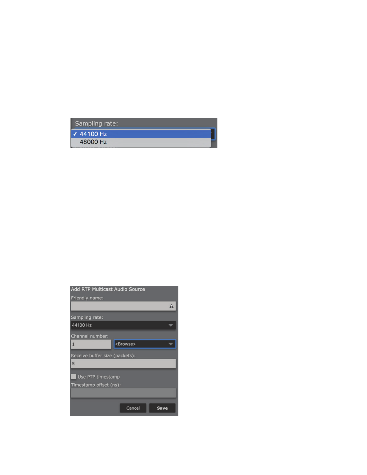
RTP: Local port
Allows input via a unicast RTP stream on a user-defined IP port. Selecting this option will open the “Add RTP Audio
Source” panel.
Page 37
AUDIO SOURCE CONFIGURATION
Friendly name
Since many audio source names on the system can be very similar, give this audio source a “Friendly” name that
will be easier to remember when configuring processing and encoding instances (for example, Livewire 1, AES 1,
Classical, Jazz, or whatever else will make it easier to identify in R/2).
Sampling rate
This is the sample rate that the streams from this audio channel will be generated at. Available options are 44.1 kHz
or 48 kHz. Choose whichever sample rate best suits the streaming application.
RTP Port
Enter the port that will receive this RTP audio stream.
Receive Buffer Size (Packets)
Allows precise adjustment of the incoming RTP audio stream buffer for time alignment, or other purposes.
SECTION 7
| 26
Use PTP timestamp
Specifies use of an IEEE 1588 PTP (Precision Time Protocol) timestamp for stream synchronization purposes.
Timestamp offset (ns)
Allows an offset to the incoming IEEE 1588 PTP timestamp to be specified.
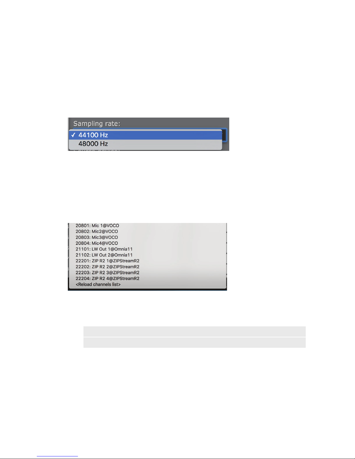
RTP: Multicast
Allows input via a multicast RTP stream (including Livewire+/AES67). Selecting this option will open the “Add
RTP Multicast Audio Source” panel.
Page 38
AUDIO SOURCE CONFIGURATION
Friendly name
Since many audio source names on the system can be very similar, give this audio source a “Friendly” name that
will be easier to remember when configuring processing and encoding instances (for example, Livewire 1, AES 1,
Classical, Jazz, or whatever else will make it easier to identify in R/2).
Sampling rate
This is the sample rate that the streams from this audio channel will be generated at. Available options are 44.1 kHz
or 48 kHz. Choose whichever sample rate best suits the streaming application.
Channel number
Specifies the Livewire or other Audio over IP network channel number associated with the desired RTP multicast
stream.
SECTION 7
| 27
Browse
Displays a list of multicast channels and streams available on the network. Select a channel from this list to
populate the “Channel number” field. Select “Reload channels list” to refresh this list of available channels.
Note:
Both this method and the “Livewire Driver” method described later in this chapter can be used to
dene Livewire channels as available audio sources.
Use PTP timestamp
Specifies use of an IEEE 1588 PTP (Precision Time Protocol) timestamp for stream synchronization purposes.
Timestamp offset (ns)
Allows an offset to the incoming IEEE 1588 PTP timestamp to be specified.
Page 39
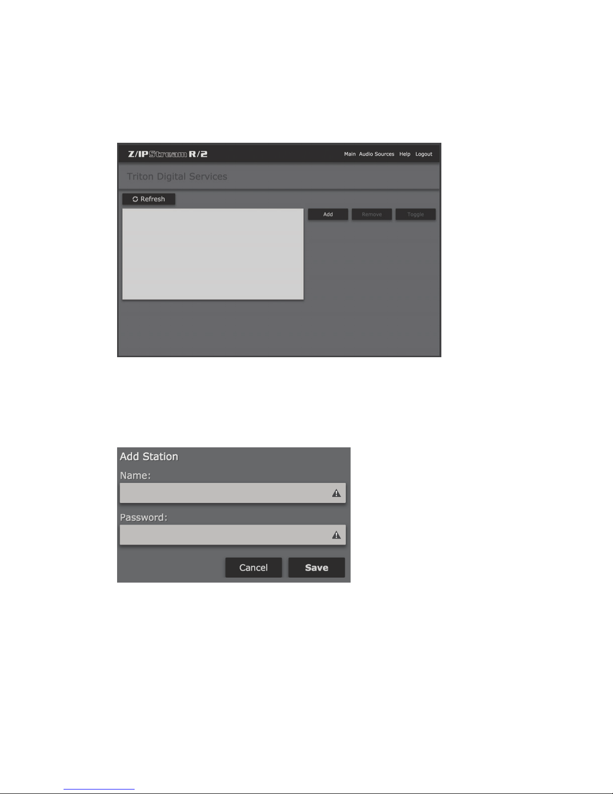
AUDIO SOURCE CONFIGURATION
Triton Digital Services
SECTION 7
| 28
R/2 offers a direct streamlined interface to Triton Digital Services for streaming and ad replacement. Stations can
be added to R/2 via the “Triton Digital Services” screen. This screen also allows stations to be removed from R/2,
or toggled on and off.
Adding a Triton Digital Services Station
Enter the Triton Digital Services login and password for the station you wish to add and click “Save”.
Click “Remove” to remove a station from the list, or “Toggle” to enable and disable a station.
Click “Main” to return to the main R/2 “Control Panel” screen, or “Audio Sources” to return to audio source
configuration.
Page 40
AUDIO SOURCE CONFIGURATION
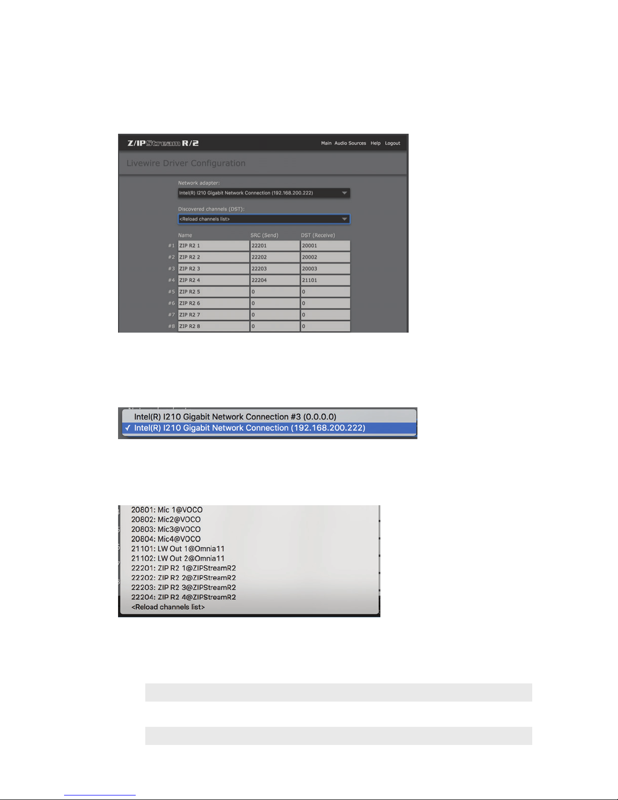
Livewire Driver
The “Livewire Driver Configuration” screen allows configuration of the integrated Livewire IP Audio Driver and
provides a direct mechanism for defining the Livewire channel names and numbers used by R/2. Up to 24 Livewire
channels are available and correspond to the 24 Livewire channels available via the “Source Device” menu under
“Add Wave Audio Source”.
SECTION 7
| 29
Network Adapter
Select the desired network interface for to be used for Livewire traffic. The IP addresses listed for these two
interfaces should correspond to the ones assigned for NIC 1 and NIC 2.
Discovered channels (DST)
Displays a list of Livewire channels available on the network. This list is for reference only. Selecting channels in
this list will not directly populate the channel number fields. Select “Reload channels list” to refresh this list of
available channels.
Note:
If no channels are displayed in this list, rst verify that one of the NIC interfaces is connected to the
Livewire network and properly congured. Second, attempt to restart the R/2 service (not the entire
R/2 unit, just the R/2 “service” via the “Services” menu under “Options”—Refer to Chapter 14 for
details)
Page 41

AUDIO SOURCE CONFIGURATION
Name
Enter a name to uniquely identify this channel on the Livewire network. It will appear on other Livewire devices as
name@ZIPStreamR2 (see the above channel list for an example).
SRC (Send)
Enter a unique Livewire network channel number from 1 to 32767 that each IP audio driver channel will SEND to
as a SOURCE. Enter “0” to disable sending to the Livewire network from a channel.
Note:
Each device MUST use unique channel numbers when sending audio to the Livewire network. It is
recommended that you develop a channel numbering scheme to ensure that every device on the
network is always assigned a unique block of channel numbers. For example, the last octet of the IP
address with the channel number appended is one such example. In this case, the channel numbers
assigned to this particular R/2 would be 22201-22224.
DST (Receive)
This section allows R/2 to RECEIVE audio as a DESTINATION FROM the Livewire network. Using the “Discovered Channels” list, enter a valid channel number from the Livewire network to assign it to an audio driver channel.
Audio from this network channel will appear on the corresponding Livewire driver channel in the “Source Device”
menu under “Add Wave Audio Source”.
SECTION 7
| 30
Click “Main” to return to the main R/2 “Control Panel” screen, or “Audio Sources” to return to audio source
configuration.
Page 42

8 Processing and Encoding
Overview
Once the audio sources have been defined, the next step is to configure the processing and encoding instances that
will use those sources. Each audio source can be used for audio processing only, encoding only, or any combination
of the two. Available encoding modes include AAC, MP3, and adaptive AAC. Multiple codecs, bitrates and encoding destinations are supported for each audio source. This is potentially one of the most complex yet extremely
powerful configuration sections within R/2.
Dening Processing and Encoding Instances
SECTION 8
| 31
From the Main “Control Panel” window, click “New”.
Page 43
PROCESSING AND ENCODING
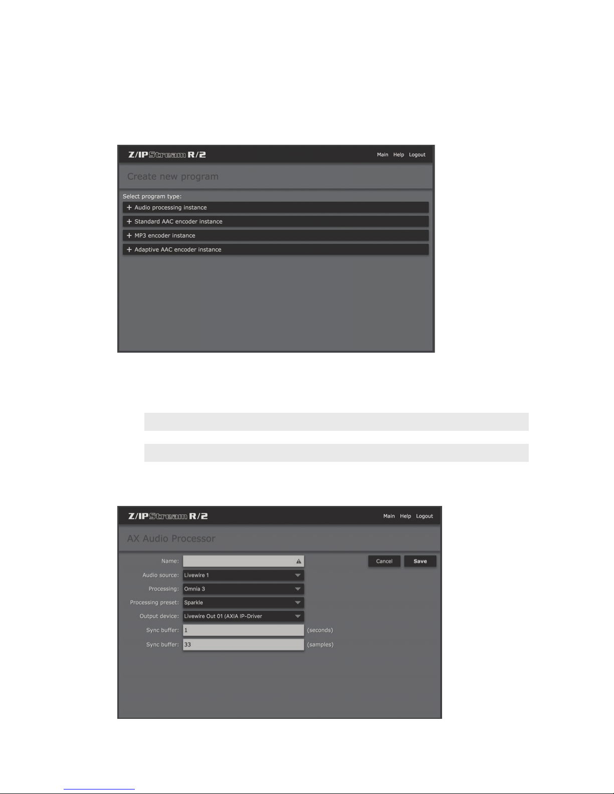
Create New Program
SECTION 8
| 32
The “Create New Program” window allows selection of the “program type” to be defined. Click on the program
type that you wish to create.
Note:
Multiple processing and/or encoding instances (program types) are supported for each of the audio
sources dened previously (see Chapter 7). Encoder instances can also contain multiple destinations
and bitrates for encoding.
Audio processing instance
Page 44
PROCESSING AND ENCODING
While R/2 is designed primarily for streaming applications, there may be cases where you wish to process an audio
signal without encoding a stream for a server. The “Audio Processing Instance” program allows processing an audio
I/O without encoding. This can be useful for “utility” processing of audio around a facility, or as “backup” to a main
audio processor, particularly when using the optional Omnia.9 processing.
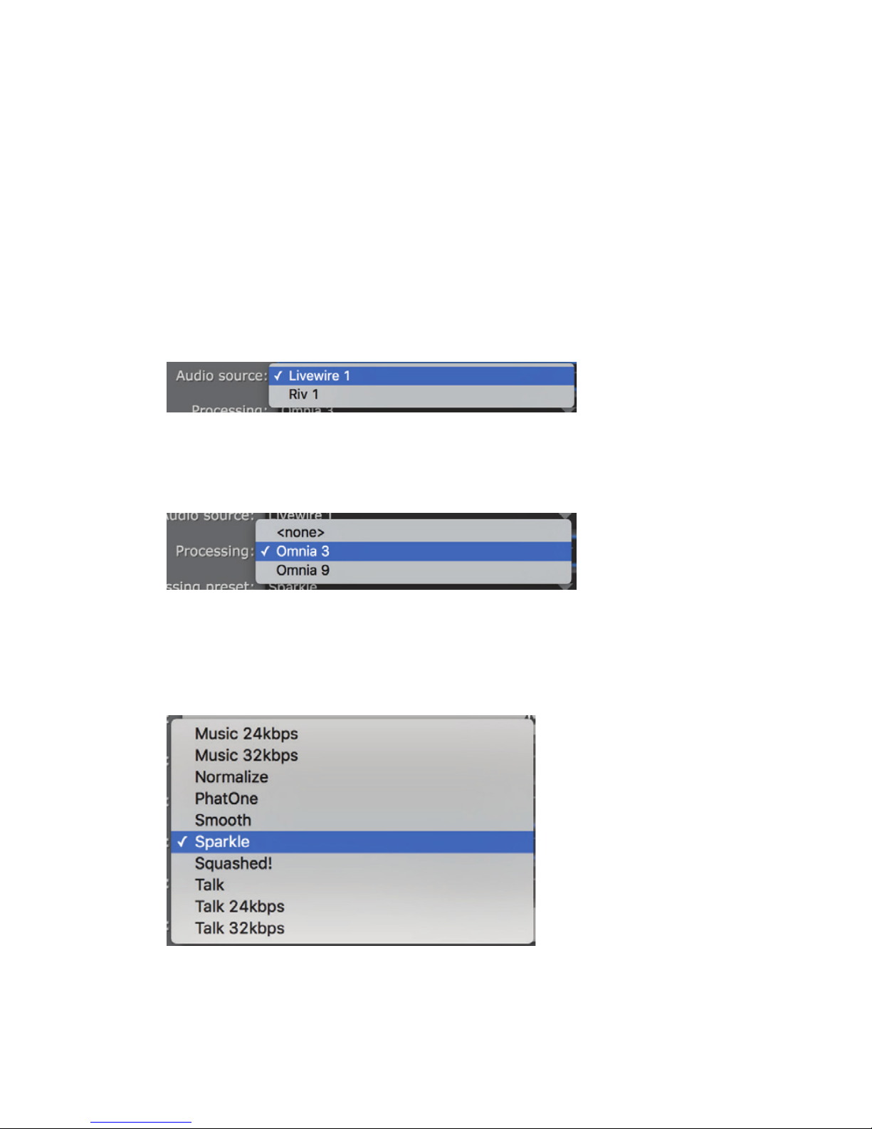
Name
Enter a “friendly name” for this processing instance to easily identify it for status and control from the main
“control panel” screen (i.e. Kxxx-Backup Processing).
Audio Source
Select one of the previously defined audio sources as the input to this processing instance (see Chapter 7). Note
that these sources can be used in multiple processing or encoding instances simultaneously.
Processing
SECTION 8
| 33
Selects between Omnia 3 and optional Omnia.9 processing (or no processing at all, should you simply want to
route audio through this instance without processing). Up to 8 channels of Omnia.9 processing can be licensed per
R/2. When you have reached the maximum number of Omnia.9 licenses available (or if Omnia.9 processing is not
licensed) this option will not be displayed. See Chapter 16 for more information on Omnia.9 processing.
Processing preset
Selects the processing preset to be used for this instance. When Omnia 3 processing is selected, the list of available
presets will appear. These presets are not format specific, though there are bitrate specific presets for “Music” and
“Talk”. Experiment with various presets to find one that works best for your programming format and application.
Presets can be copied and modified to create a sound customized exactly to your needs. See Chapter 9 to learn how
to “fine tune” the Omnia 3 processing, and Chapter 13 for more information on Omnia 3 preset management.
Page 45
PROCESSING AND ENCODING
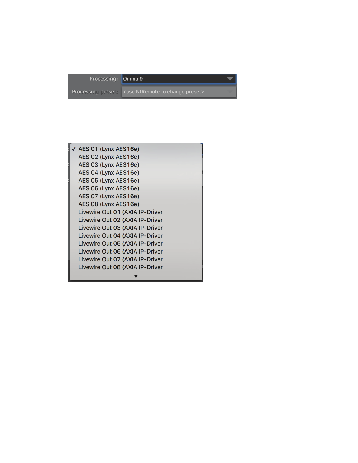
If optional Omnia.9 processing is enabled, the preset must be selected via NfRemote software due to the powerful
processing tools and test instrumentation available through Omnia.9. See Chapter 16 for more details.
Output device
SECTION 8
| 34
The available output destinations for audio from this instance are listed here (up to 24 Livewire outputs, and 8
local AES outputs). Select the output destination for this processing instance. Livewire channels are configured
through the “Livewire Driver Configuration” interface. See Chapter 7 for more details.
Sync buffer (Samples, Seconds)
These values will allow adjustment of the synchronization buffer between input and output. It is recommended
that you leave these at the defaults unless advised by technical support. Improper adjustment can cause buffering
issues.
Cancel/Save
Once you have finished configuring the processing instance, click “Save” to save it, or “Cancel” to return to the
Control Panel screen without saving changes.
Page 46
PROCESSING AND ENCODING
Standard AAC Encoder Instance
SECTION 8
| 35
The Standard AAC Encoder instance accepts audio from a source, encodes it to AAC, and then passes the encoded
stream along to one or more servers that you specify. Remember that that the encoded stream can be sent simultaneously to multiple servers, which will then replicate the stream to the client. Multiple AAC bitrates, formats, or
processing parameters are supported from the same audio source by creating multiple AAC encoder instances.
Name
Enter a “friendly name” for this encoder instance to easily identify it for status and control from the main “control
panel” screen (i.e. Kxxx-AAC Stream 1).
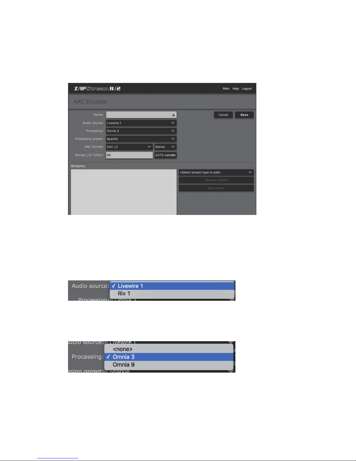
Audio Source
Select one of the previously defined audio sources as the input to this processing instance (see Chapter 7). Note
that these sources can be used in multiple processing or encoding instances simultaneously.
Processing
Selects between Omnia 3 and optional Omnia.9 processing (or no processing at all, should you simply want to
route audio through this instance without processing). Up to 8 channels of Omnia.9 processing can be licensed per
R/2. When you have reached the maximum number of Omnia.9 licenses available (or if Omnia.9 processing is not
licensed) this option will not be displayed. See Chapter 16 for more information on Omnia.9 processing.
Page 47
PROCESSING AND ENCODING
Processing preset
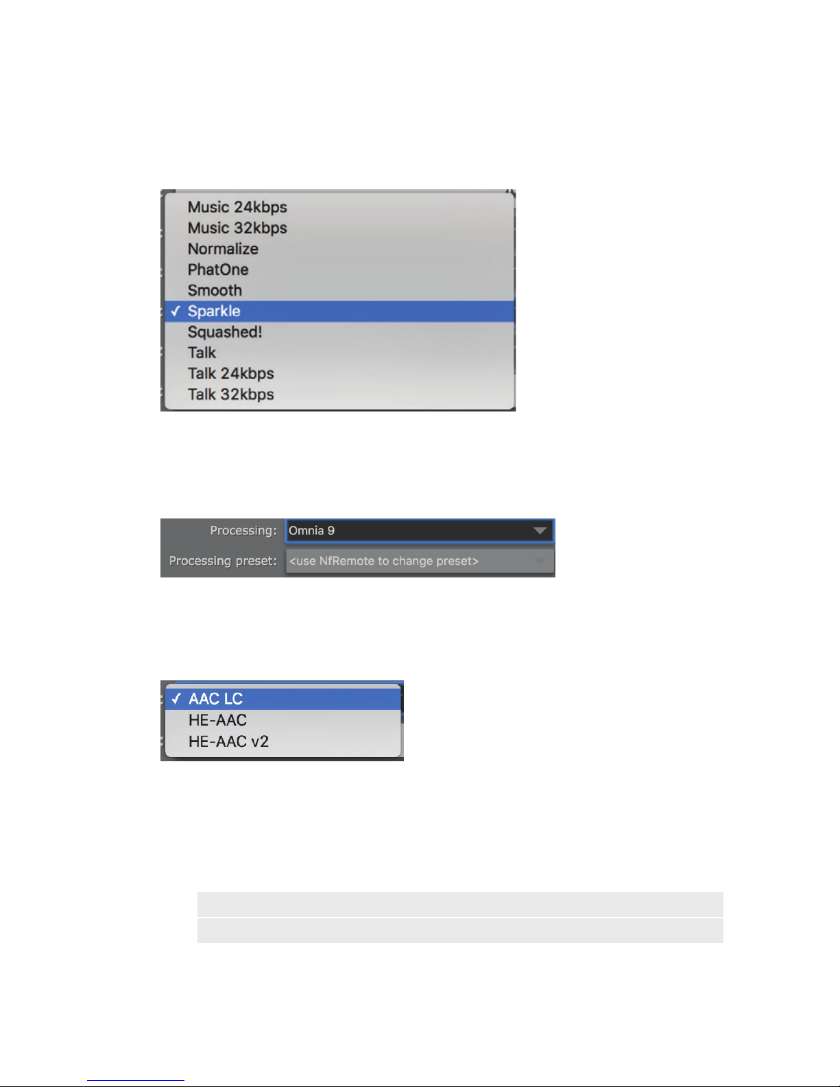
Selects the processing preset to be used for this instance. When Omnia 3 processing is selected, the list of available
presets will appear. These presets are not format specific, though there are bitrate specific presets for “Music” and
“Talk”. Experiment with various presets to find one that works best for your programming format and application.
Presets can be copied and modified to create a sound customized exactly to your needs. See Chapter 9 to learn how
to “fine tune” the Omnia 3 processing, and Chapter 13 for more information on Omnia 3 preset management.
SECTION 8
| 36
If optional Omnia.9 processing is enabled, the preset must be selected via NfRemote software due to the powerful
processing tools and test instrumentation available through Omnia.9. See Chapter 16 for more details.
AAC Format
There are several different “flavors” of AAC. The most common form (and the default for this instance) is AAC-LC
(Advanced Audio Coding-Low Complexity). HE-AAC is “High Efficiency” AAC. It is designed for bitrates between
24 and 96 kbps. An “improved” version of HE-AAC (HE-AAC v2) was developed for lower bitrates between 14 and
56 kbps. HE-AAC v2 also offers improved stereo performance at lower bitrates. It is worth noting while HE-AAC v2
is widely supported, it may not be compatible with some players.
Note:
If in doubt, choose AAC-LC. This is the most common form of AAC encoding, though the HE (High
Eciency) variants are becoming more common for lower bitrate applications.
Page 48
PROCESSING AND ENCODING
Mono/Stereo
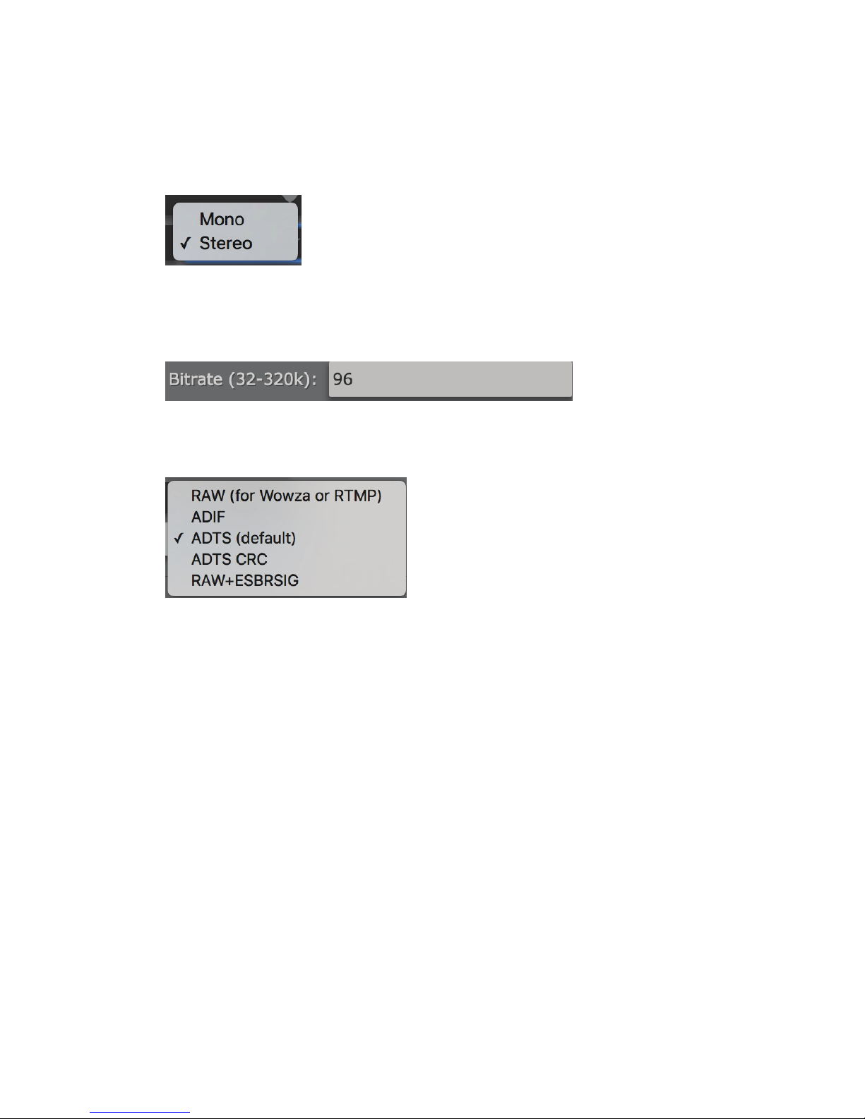
Select whether this stream will be encoded in Mono or Stereo. Mono should provide a mono sum of the incoming
audio. This setting will be locked to stereo for HE-AAC v2.
Bitrate
Enter the bitrate for this stream. The valid bitrate range will change depending on which AAC format is selected.
Stream Output Format
SECTION 8
| 37
Selects the output file format for the stream. Even though the streams are not a “file” per-se, this setting controls
how the AAC encoded audio is encapsulated. The default is generally sufficient for most applications, but other
settings may be required for different server platforms (such as Wowza or other RTMP server). Although multiple
server destinations are supported per instance, only one output format can be selected. Use another instance if you
need to send a different format to another server (i.e. HTTP server and Wowza/RTMP simultaneously).
♦ RAW – Send unformatted (raw encoded) audio to your stream. Use this option with RTMP streams.
♦ ADIF - Audio Data Interchange Format, a file format to exchange AAC data.
♦ ADTS - Audio Data Transport Stream, a format, used by all other stream types.
♦ RAW+ESBRSIG – Send unformatted audio along to your stream that includes explicit backwards
compatible signaling method. This option can be used with RTMP streams.
Page 49
PROCESSING AND ENCODING
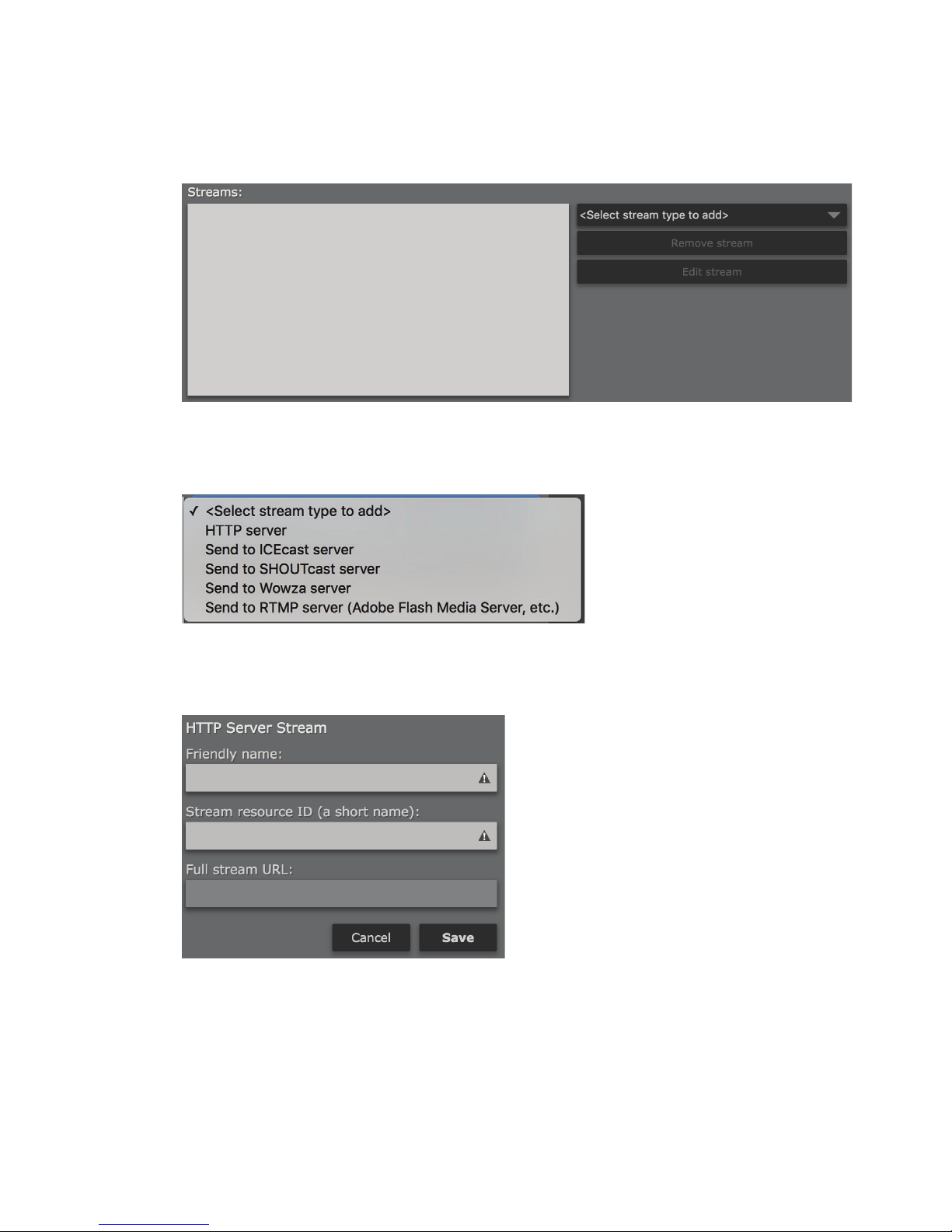
Adding Streams
Multiple server destinations can be specified for each encoder instance. To add a destination, click on “Select
stream type to add”. Supported server destinations include HTTP, Icecast, SHOUTcast, Wowza, or other RTMP
(Adobe Flash Media Server, etc.)
SECTION 8
| 38
From the dropdown menu, select the server type that you wish to send an output from this encoder instance to.
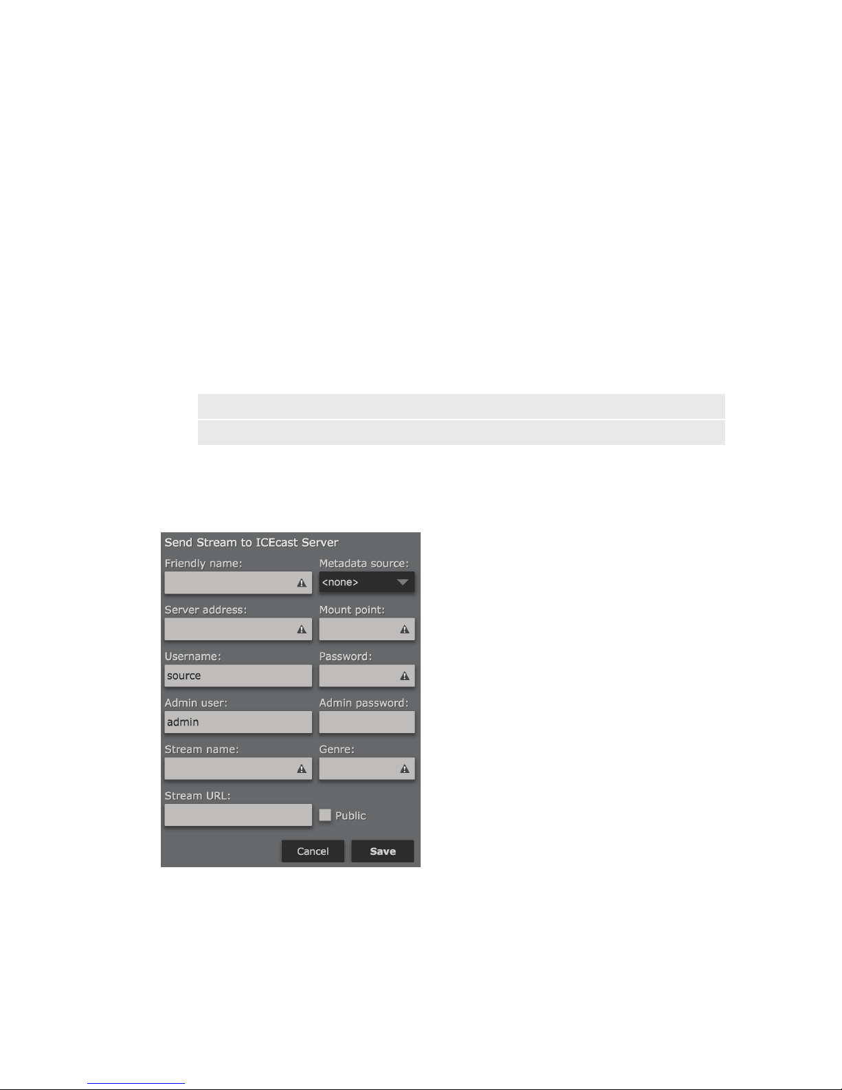
HTTP Server
The HTTP option will send the output to the HTTP stream server built into R/2. Using this server, you can monitor
the encoded stream directly from R/2. This is often helpful in troubleshooting server connections, or just as a quick
way to test that everything is working as expected. The HTTP server is also useful when setting up audio process-
Page 50
PROCESSING AND ENCODING
ing, as the delay is much shorter than that experienced with an external server.
Friendly Name
Specify an easy to remember “Friendly” name to identify this stream output in the list of streams that have been
defined (i.e. Kxxx – Internal Test Stream).
Stream resource ID
This resource ID will become part of the URL that you use to reach this stream. For example, if the stream server
is active on port 8888, and you use a resource ID of “TestStream” then you would listen to this stream by entering
http://ip_address_of_r2:8888/TestStream in your browser or media player.
Full stream URL
Displays the full URL of this HTTP stream (including the port and Stream resource ID).
Note:
As of this writing, R/2 currently displays “localhost” rather than the actual IP address of R/2. Replace
“localhost” in the URL with the IP address or hostname of R/2.
When finished, click “Save” to save and return to the “AAC Encoder” screen or click “Cancel” to cancel any changes.
SECTION 8
| 39
Send to ICEcast Server
The ICEcast Server option allows sending a stream to an ICEcast (or compatible) server. ICEcast is an open source
streaming server available as a free download for various platforms. A separate option is provided for SHOUTcast
compatible servers.
Friendly name
Specify an easy to remember “Friendly” name to identify this stream output in the list of streams that have been
defined (i.e. Kxxx – Icecast Stream).
Page 51

PROCESSING AND ENCODING
Metadata source
Select a metadata input source to be used with this encoding instance (if desired). See Chapter 10 for more details.
Server address
Enter the IP address and port of the ICEcast server.
Mount point
Each ICEcast server may contain multiple broadcasts (or mount points) each containing a separate stream of
content. Thus, ‘mount point’ is just a unique name that identifies a particular stream. The mount point needs to be
configured properly in order for the stream to work. Mount points should not contain any spaces or odd characters.
Username
Enter a user name here for access to the audio stream. This should be the same username configured on your
ICEcast server for sources. The default username is “source”.
Password
Enter the password configured on your ICEcast server for encoding sources.
(You DID change it, didn’t you? Please tell me it isn’t still set to “hackme”)
Admin user
Enter the “admin” username for your ICEcast server. The default is “admin”.
This user will be used for the metadata functions of ICEcast.
SECTION 8
| 40
Admin password
Enter the administrator password configured on your ICEcast server here.
(Again, I REALLY hope it isn’t still set to “hackme”)
Stream name
Enter a name for your stream. This will be used for stream directory listings (if enabled) and displayed in the
stream metadata.
Genre
Enter the format of your stream or station here, for example rock, country or urban. ICEcast will display this
information in the metadata field.
Stream URL
Enter a URL to be displayed with the stream metadata. This can be a station’s website, or other URL associated with
the stream.
Check the Public checkbox to list this stream in public directories, or leave it un-checked if you do not want the
stream listed.
Note:
Even with the “Public” checkbox un-checked, it may still be possible for stream “aggregators” to nd
and list your stream as they crawl the Internet searching for publicly available audio streams. There
are very few practical ways to avoid this, unfortunately.
When finished, click “Save” to save and return to the “AAC Encoder” screen or click “Cancel” to cancel any changes.
Page 52
PROCESSING AND ENCODING
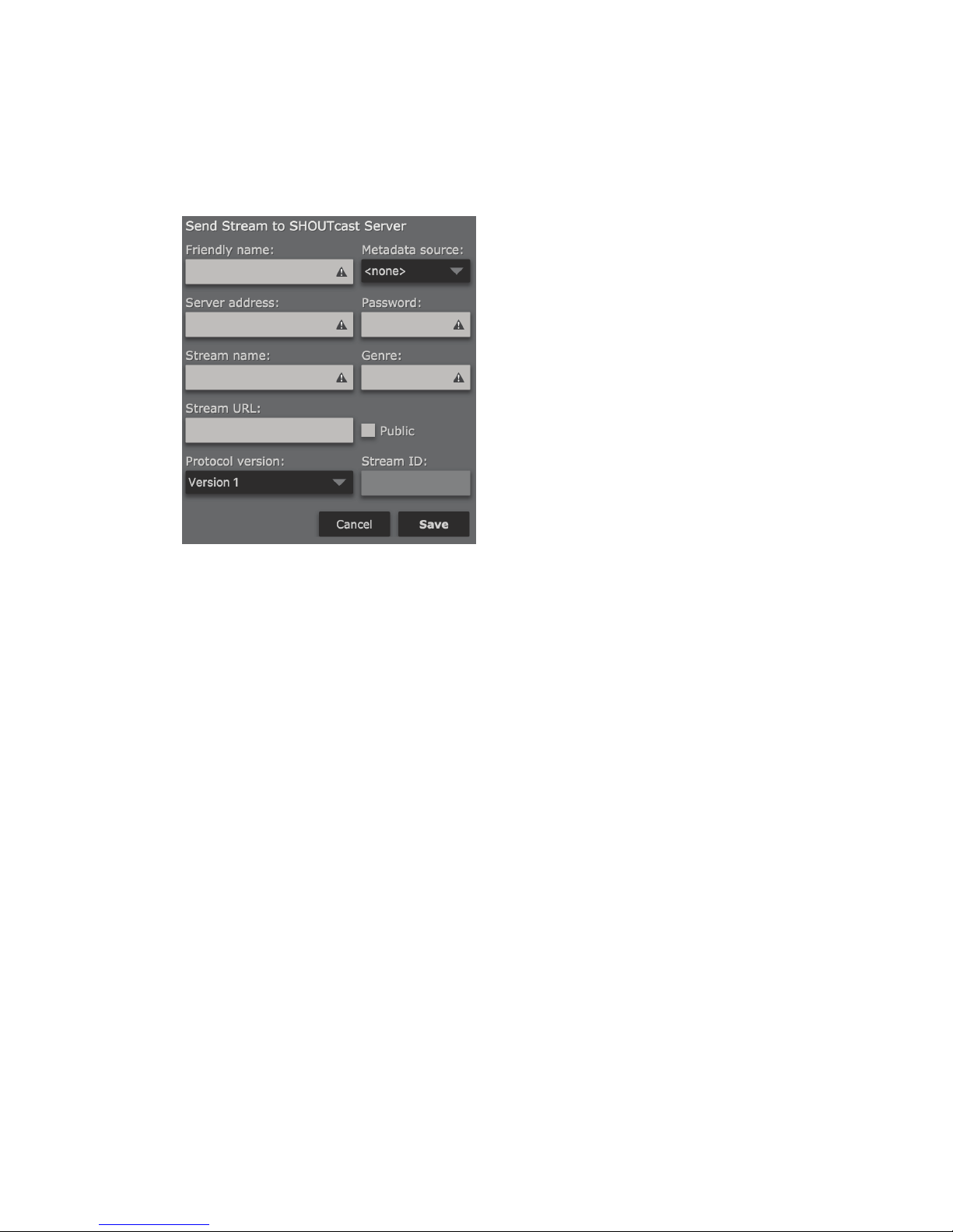
Send to SHOUTcast Server
SECTION 8
| 41
SHOUTcast DNAS (Distributed Network Audio Software) is a media server developed by Nullsoft, now distributed by Radionomy. SHOUTcast is available in multiple levels from from a basic (free) version, through paid options
that allow monetization. Currently it is available for Windows, Linux and Mac OSX. Cloud-hosted options are also
available.
R/2 replaces the DSP encoding plugin for Winamp normally used for broadcasting to a SHOUTcast server.
Friendly name
Specify an easy to remember “Friendly” name to identify this stream output in the list of streams that have been
defined (i.e. Kxxx – SHOUTcast Stream).
Metadata source
Select a metadata input source to be used with this encoding instance (if desired). See Chapter 10 for more details.
Server address
Enter the IP address and port of the SHOUTcast server.
Password
Enter the password configured on your SHOUTcast server for encoding sources.
Stream name
Enter a name for your stream. This will be used for stream directory listings (if enabled) and displayed in the
stream metadata.
Genre
Enter the format of your stream or station here, for example rock, country or urban. SHOUTcast will display this
information in the metadata field.
Stream URL
Enter a URL to be displayed with the stream metadata. This can be a station’s website, or other URL associated with
the stream.
Page 53

PROCESSING AND ENCODING
Check the Public checkbox to list this stream in public directories, or leave it un-checked if you do not want the
stream listed.
Note:
Even with the “Public” checkbox un-checked, it may still be possible for stream “aggregators” to nd
and list your stream as they crawl the Internet searching for publicly available audio streams. There
are very few practical ways to avoid this, unfortunately.
Protocol Version
Choose between SHOUTcast Version 1 or Version 2, depending on the requirements of your SHOUTcast server
platform.
Stream ID
Specify the numerical identifier of the stream for control or referencing the stream configuration. This can only be
a numeric value from 1 to 2147483647.
When finished, click “Save” to save and return to the “AAC Encoder” screen or click “Cancel” to cancel any changes.
Send to Wowza server
SECTION 8
| 42
R/2 offers direct integration with Wowza servers for easy configuration of encoding parameters. Configuration
files can be loaded into R/2 as an XML file downloaded from the Wowza server, XML configuration copy/paste, or
manually configured.
Note:
In order to send AAC encoded audio to a Wowza server, you must use “Raw” for the stream le
output format, as described earlier in this chapter. Other stream le formats cannot be used
simultaneously in the same instance (i.e. ADTS for the internal HTTP server or other servers). Create
a new instance if you wish to use another stream le format simultaneously.
Although it can be disabled, Wowza is set by default to use authentication for RTMP encoding sources such as R/2, and it is
highly recommended. You will need to define at least one valid “Publisher” account in the “Server” setup for Wowza.
In the Wowza Streaming Engine Manager console, Navigate to “Server”, then to “Source Authentication”. Click on
“Add Source” and specify a username and password. This is necessary for both XML-based and manual configuration of a Wowza stream in R/2.
Page 54
PROCESSING AND ENCODING
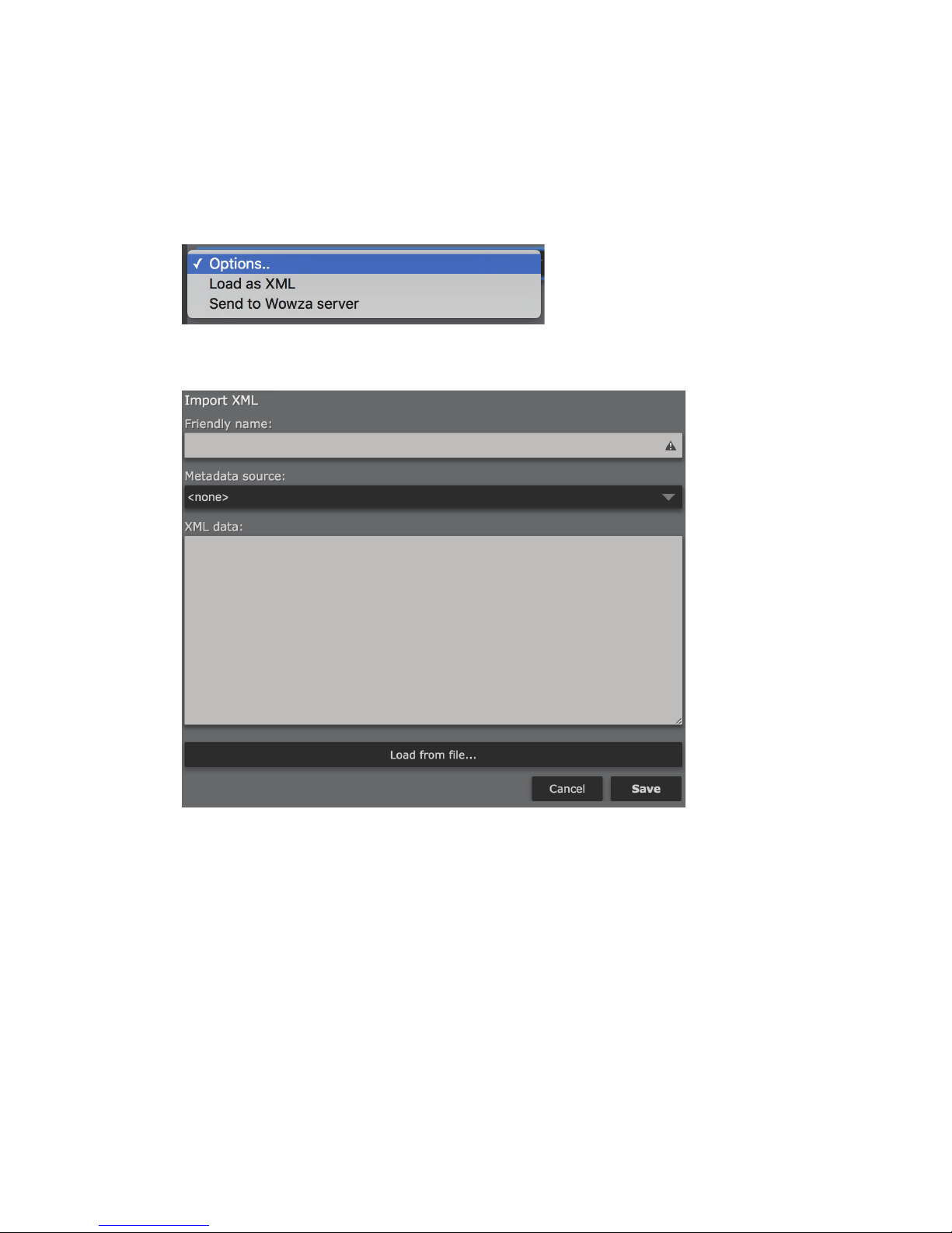
Configuring R/2 for a Wowza stream
Click on the “Options” dropdown to choose a method for configuring a Wowza connection.
Load as XML
SECTION 8
| 43
Allows loading an XML configuration for a Wowza connection either from a file, or by copy/paste.
This file can be downloaded from the Wowza server by clicking on the desired streaming application in Wowza
(live, for example) then clicking on “Incoming Publishers”. Select “The Telos Alliance” from the list of available
encoder manufacturers. The appropriate configuration parameters will appear, along with a button to download an
XML file containing the configuration for R/2. You will also need to define an account for the incoming source.
Friendly name
Specify an easy to remember “Friendly” name to identify this stream output in the list of streams that have been
defined (i.e. Kxxx – Wowza Stream).
Metadata source
Select a metadata input source to be used with this encoding instance (if desired). See Chapter 10 for more details.
XML data
Copy and paste the XML configuration data for this connection from the Wowza server here.
Page 55
PROCESSING AND ENCODING
Load from file
Click here to load Wowza XML configuration data from a file.
When finished, click “Save” to save and return to the “AAC Encoder” screen or click “Cancel” to cancel any changes.
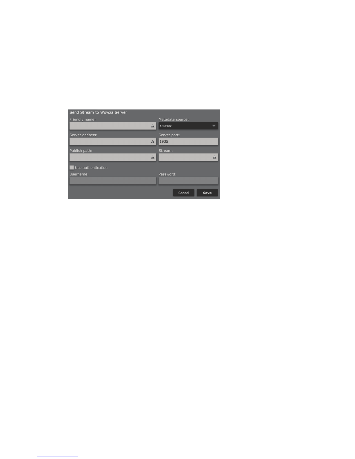
Send to Wowza Server
Allows manual configuration of a stream pushed to a Wowza server.
SECTION 8
| 44
Friendly name
Specify an easy to remember “Friendly” name to identify this stream output in the list of streams that have been
defined (i.e. Kxxx – Wowza Stream).
Metadata source
Select a metadata input source to be used with this encoding instance (if desired). See Chapter 10 for more details.
Server address
Enter the IP address of the Wowza server.
Server port
Enter the port of the Wowza server. The default is 1935.
Publish path
Enter the path to the desired streaming application on your Wowza server (live, for example).
Stream
Enter the name of the stream you wish to create on your Wowza server. This stream will be created under the
specified path (application).
Use Authentication
Check this box to use authentication when sending a stream to the Wowza server. Authentication for RTMP
publisher sources such as R/2 is enabled by default in Wowza and will likely need to be enabled here as well.
Username
Enter the username specified as a publisher in the Wowza server.
Password
Enter the password associated with the publisher username in the Wowza server.
Page 56
PROCESSING AND ENCODING
When finished, click “Save” to save and return to the “AAC Encoder” screen or click “Cancel” to cancel any changes.
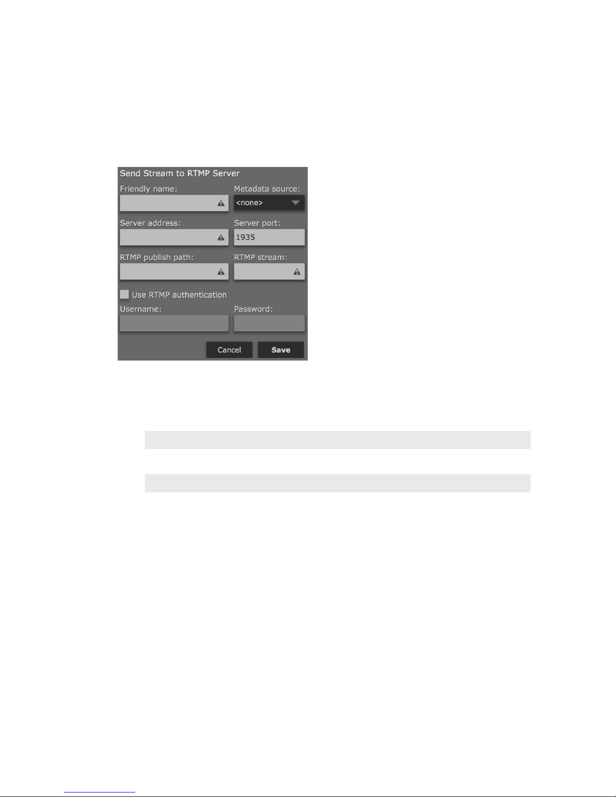
Send to RTMP Server
SECTION 8
| 45
RTMP (Real Time Messaging Protocol) is a TCP-based protocol initially developed by Macromedia to deliver
streams to the Flash player. The specification is now available (albeit in incomplete form) for public use. A number
of servers support the RTMP protocol, including Adobe Flash Media Server, Wowza and others.
Note:
In order to send AAC encoded audio to an RTMP server, you must use “Raw” for the stream le
output format, as described earlier in this chapter. Other stream le formats cannot be used
simultaneously in the same instance (i.e. ADTS for the internal HTTP server or other servers). Create
a new instance if you wish to use another stream le format simultaneously.
Friendly name
Specify an easy to remember “Friendly” name to identify this stream output in the list of streams that have been
defined (i.e. Kxxx – RTMP Stream).
Metadata source
Select a metadata input source to be used with this encoding instance (if desired). See Chapter 10 for more details.
Server address
Enter the IP address of the RTMP server.
Server port
Enter the port of the RTMP server. The default is 1935.
RTMP Publish path
Enter the publishing path for the RTMP server—generally provided by your CDN, and may also be referred to as an
“entry point”.
RTMP Stream
Enter the name of the RTMP stream name. The stream name may be fixed or chosen, it depends on your CDN.
Page 57
PROCESSING AND ENCODING
Some providers, such as Akamai, require the stream name to be very specific, and they provide the format that
must be used.
Use RTMP Authentication
Check this box to use authentication when sending a stream to the RTMP server.
Username
Enter the username for encoding to your RTMP server.
Password
Enter the password for encoding to your RTMP server.
When finished, click “Save” to save and return to the “AAC Encoder” screen or click “Cancel” to cancel any changes.
MP3 Encoder Instance
SECTION 8
| 46
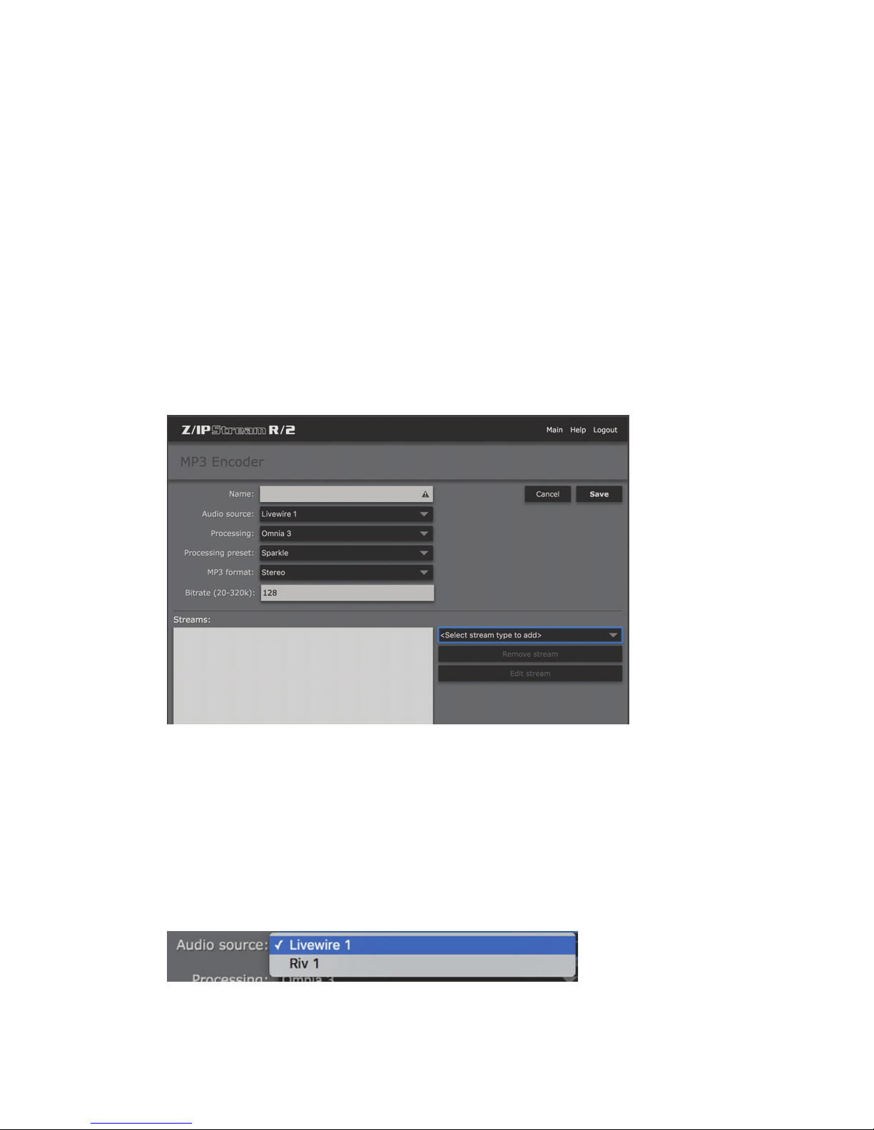
An MP3 Encoder instance accepts data from an audio source, processes it, encodes it to MPEG Layer-3, and makes
it available to media servers. The encoded stream can also be made available through the HTTP stream server built
into the application. The internal HTTP server is intended for monitoring the stream by a very small number of
listeners. It is not designed to feed a large number of clients.
Name
Enter a “friendly name” for this encoder instance to easily identify it for status and control from the main “control
panel” screen (i.e. Kxxx-MP3 Stream 1).
Audio Source
Select one of the previously defined audio sources as the input to this processing instance (see Chapter 7). Note
that these sources can be used in multiple processing or encoding instances simultaneously.
Page 58
PROCESSING AND ENCODING
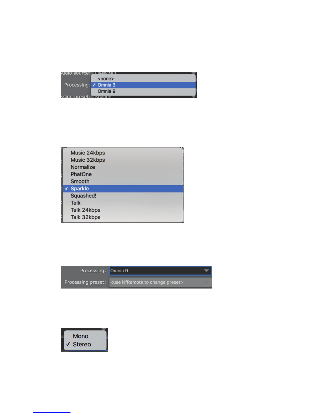
Processing
Selects between Omnia 3 and optional Omnia.9 processing (or no processing at all, should you simply want to
route audio through this instance without processing). Up to 8 channels of Omnia.9 processing can be licensed per
R/2. When you have reached the maximum number of Omnia.9 licenses available (or if Omnia.9 processing is not
licensed) this option will not be displayed. See Chapter 16 for more information on Omnia.9 processing.
Processing preset
SECTION 8
| 47
Selects the processing preset to be used for this instance. When Omnia 3 processing is selected, the list of available
presets will appear. These presets are not format specific, though there are bitrate specific presets for “Music” and
“Talk”. Experiment with various presets to find one that works best for your programming format and application.
Presets can be copied and modified to create a sound customized exactly to your needs. See Chapter 9 to learn how
to “fine tune” the Omnia 3 processing, and Chapter 13 for more information on Omnia 3 preset management.
If optional Omnia.9 processing is enabled, the preset must be selected via NfRemote software due to the powerful
processing tools and test instrumentation available through Omnia.9. See Chapter 16 for more details.
MP3 Format
Select whether this stream will be encoded in Mono or Stereo. Mono should provide a mono sum of the incoming
audio.
Page 59
PROCESSING AND ENCODING
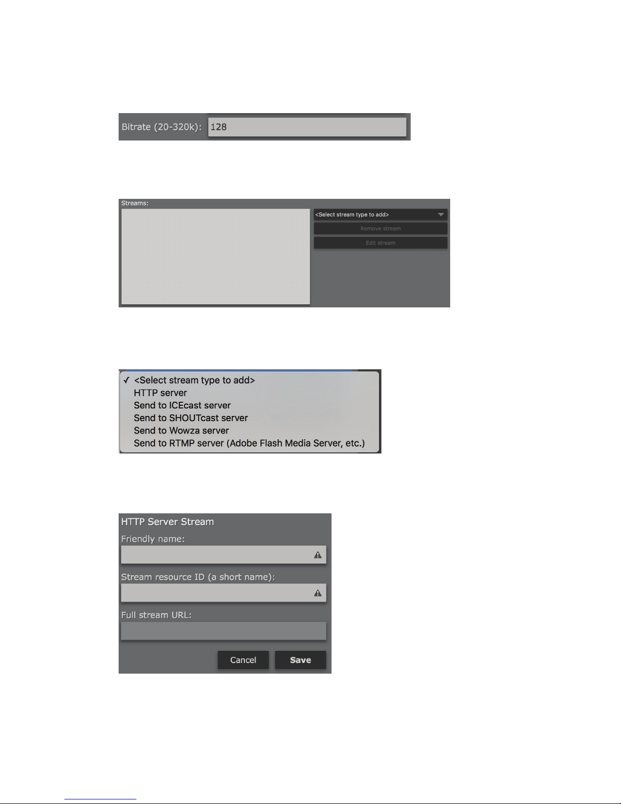
Bitrate
Enter the bitrate for this stream. Valid MP3 bitrates are 20 kbps to 320 kbps.
Adding Streams
Multiple server destinations can be specified for each encoder instance. To add a destination, click on “Select
stream type to add”. Supported server destinations include HTTP, Icecast, SHOUTcast, Wowza, or other RTMP
(Adobe Flash Media Server, etc.)
SECTION 8
| 48
From the dropdown menu, select the server type that you wish to send an output from this encoder instance to.
HTTP Server
The HTTP option will send the output to the HTTP stream server built into R/2. Using this server, you can monitor
the encoded stream directly from R/2. This is often helpful in troubleshooting server connections, or just as a quick
way to test that everything is working as expected. The HTTP server is also useful when setting up audio processing, as the delay is much shorter than that experienced with an external server.
Page 60
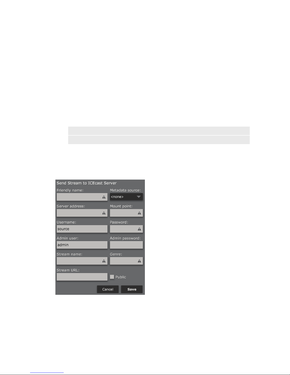
PROCESSING AND ENCODING
Friendly Name
Specify an easy to remember “Friendly” name to identify this stream output in the list of streams that have been
defined (i.e. Kxxx – Internal Test Stream).
Stream resource ID
This resource ID will become part of the URL that you use to reach this stream. For example, if the stream server
is active on port 8888, and you use a resource ID of “TestStream” then you would listen to this stream by entering
http://ip_address_of_r2:8888/TestStream in your browser or media player.
Full stream URL
Displays the full URL of this HTTP stream (including the port and Stream resource ID).
Note:
As of this writing, R/2 currently displays “localhost” rather than the actual IP address of R/2. Replace
“localhost” in the URL with the IP address or hostname of R/2.
When finished, click “Save” to save and return to the “MP3 Encoder” screen or click “Cancel” to cancel any
changes.
Send to ICEcast Server
SECTION 8
| 49
The ICECast Server option allows sending a stream to an ICEcast (or compatible) server. ICECast is an open
source streaming server available as a free download for various platforms. A separate option is provided for
SHOUTcast compatible servers.
Page 61

PROCESSING AND ENCODING
Friendly name
Specify an easy to remember “Friendly” name to identify this stream output in the list of streams that have been
defined (i.e. Kxxx – Icecast Stream).
Metadata source
Select a metadata input source to be used with this encoding instance (if desired). See Chapter 10 for more details.
Server address
Enter the IP address and port of the ICEcast server.
Mount point
Each ICEcast server may contain multiple broadcasts (or mount points) each containing a separate stream of
content. Thus, ‘mount point’ is just a unique name that identifies a particular stream. The mount point needs to be
configured properly in order for the stream to work. Mount points should not contain any spaces or odd characters.
Username
Enter a user name here for access to the audio stream. This should be the same username configured on your
ICECast server for sources. The default username is “source”.
Password
Enter the password configured on your ICECast server for encoding sources.
(You DID change it, didn’t you? Please tell me it isn’t still set to “hackme”)
SECTION 8
| 50
Admin user
Enter the “admin” username for your ICECast server. The default is “admin”.
This user will be used for the metadata functions of ICEcast.
Admin password
Enter the administrator password configured on your ICECast server here.
(Again, I REALLY hope it isn’t still set to “hackme”)
Stream name
Enter a name for your stream. This will be used for stream directory listings (if enabled) and displayed in the
stream metadata.
Genre
Enter the format of your stream or station here, for example rock, country or urban. ICECast will display this
information in the metadata field.
Stream URL
Enter a URL to be displayed with the stream metadata. This can be a station’s website, or other URL associated with
the stream.
Check the Public checkbox to list this stream in public directories, or leave it un-checked if you do not want the
stream listed.
Note:
Even with the “Public” checkbox un-checked, it may still be possible for stream “aggregators” to nd
and list your stream as they crawl the Internet searching for publicly available audio streams. There
are very few practical ways to avoid this, unfortunately.
Page 62
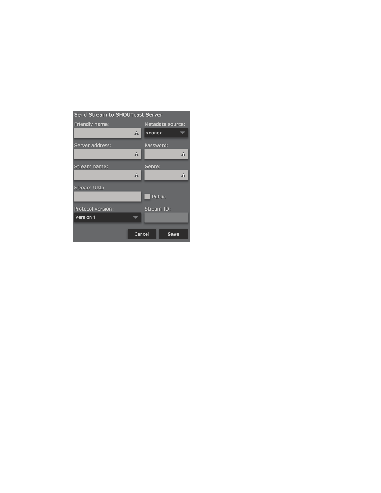
PROCESSING AND ENCODING
When finished, click “Save” to save and return to the “MP3 Encoder” screen or click “Cancel” to cancel any
changes.
Send to SHOUTcast Server
SECTION 8
| 51
SHOUTcast DNAS (Distributed Network Audio Software) is a media server developed by Nullsoft, now distributed by Radionomy. SHOUTcast is available in multiple levels from from a basic (free) version through paid options
that allow monetization. Currently it is available for Windows, Linux and Mac OSX. Cloud-hosted options are also
available.
R/2 replaces the DSP encoding plugin for Winamp normally used for broadcasting to a SHOUTcast server.
Friendly name
Specify an easy to remember “Friendly” name to identify this stream output in the list of streams that have been
defined (i.e. Kxxx – SHOUTcast Stream).
Metadata source
Select a metadata input source to be used with this encoding instance (if desired). See Chapter 10 for more details.
Server address
Enter the IP address and port of the SHOUTcast server.
Password
Enter the password configured on your SHOUTcast server for encoding sources.
Stream name
Enter a name for your stream. This will be used for stream directory listings (if enabled) and displayed in the
stream metadata.
Genre
Enter the format of your stream or station here, for example rock, country or urban. SHOUTcast will display this
information in the metadata field.
Stream URL
Enter a URL to be displayed with the stream metadata. This can be a station’s website, or other URL associated with
the stream.
Page 63
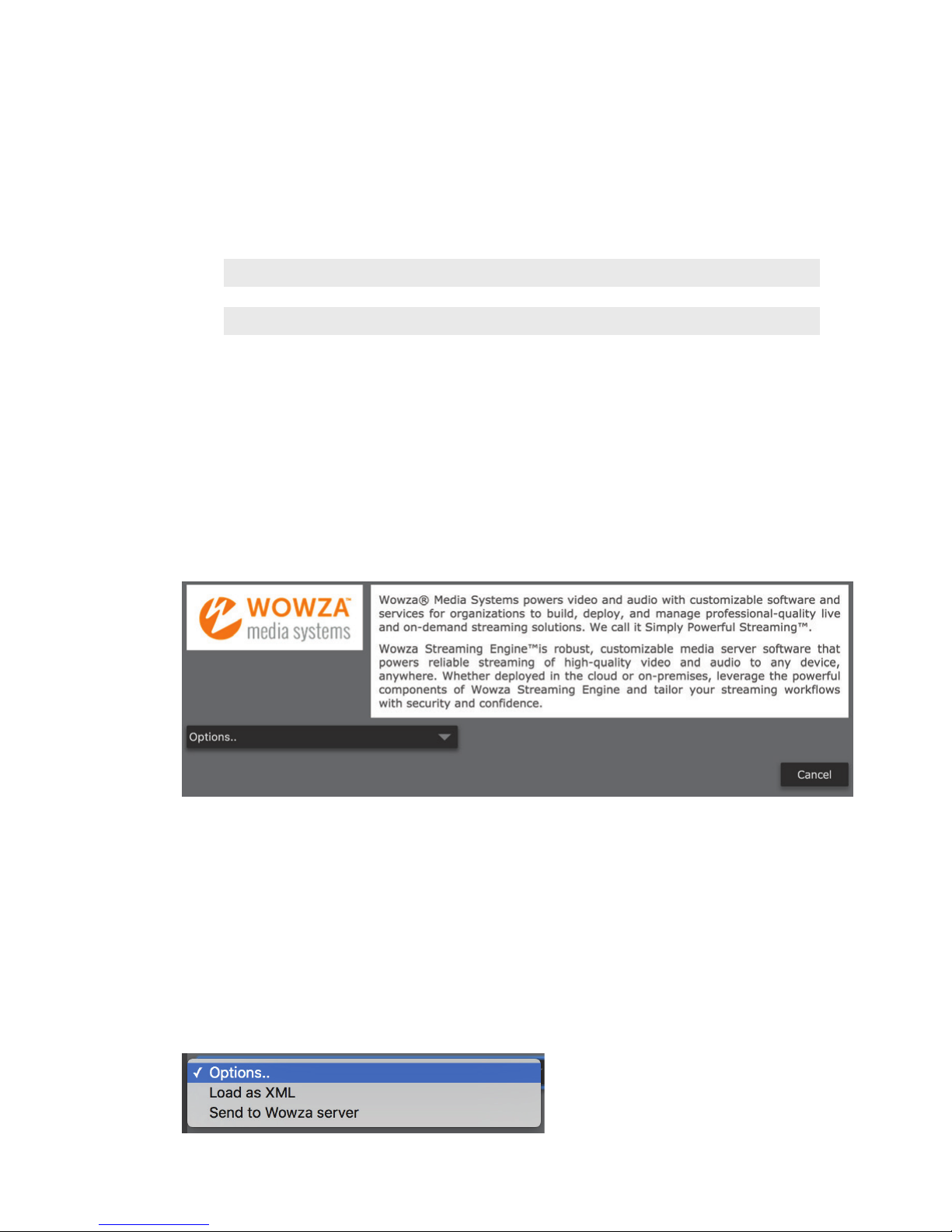
PROCESSING AND ENCODING
Check the Public checkbox to list this stream in public directories, or leave it un-checked if you do not want the
stream listed.
Note:
Even with the “Public” checkbox un-checked, it may still be possible for stream “aggregators” to nd
and list your stream as they crawl the Internet searching for publicly available audio streams. There
are very few practical ways to avoid this, unfortunately.
Protocol Version
Choose between SHOUTcast Version 1 or Version 2, depending on the requirements of your SHOUTcast server
platform.
Stream ID
Specify the numerical identifier of the stream for control or referencing the stream configuration. This can only be
a numeric value from 1 to 2147483647.
When finished, click “Save” to save and return to the “MP3 Encoder” screen or click “Cancel” to cancel any
changes.
Send to Wowza server
SECTION 8
| 52
R/2 offers direct integration with Wowza servers for easy configuration of encoding parameters. Configuration
files can be loaded into R/2 as an XML file downloaded from the Wowza server, XML configuration copy/paste, or
manually configuration.
Although it can be disabled, Wowza is set by default to use authentication for RTMP encoding sources such as R/2, and it is
highly recommended. You will need to define at least one valid “Publisher” account in the “Server” setup for Wowza.
In the Wowza Streaming Engine Manager console, Navigate to “Server”, then to “Source Authentication”. Click on
“Add Source” and specify a username and password. This is necessary for both XML-based and manual configuration of a Wowza stream in R/2.
Configuring R/2 for a Wowza stream
Click on the “Options” dropdown to choose a method for configuring a Wowza connection.
Page 64
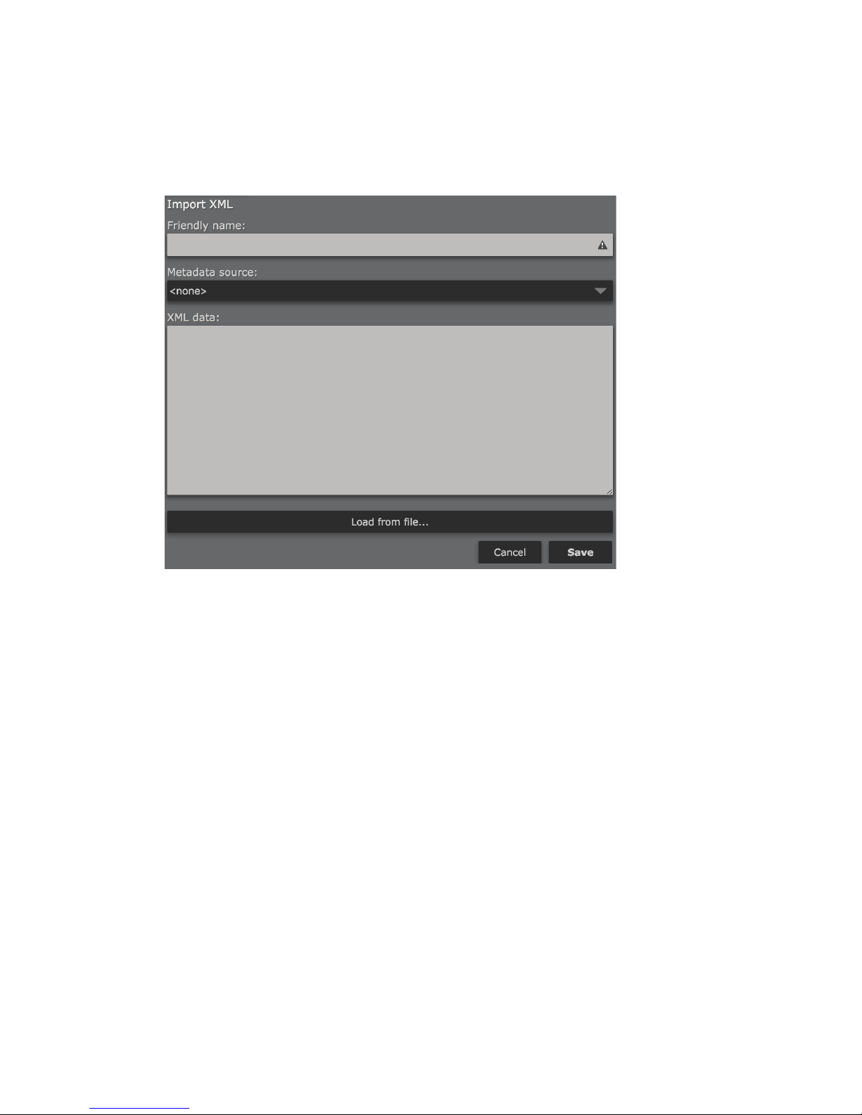
PROCESSING AND ENCODING
Load as XML
SECTION 8
| 53
Allows loading an XML configuration for a Wowza connection either from a file, or by copy/paste.
This file can be downloaded from the Wowza server by clicking on the desired streaming application in Wowza
(live, for example) then clicking on “Incoming Publishers”. Select “The Telos Alliance” from the list of available
encoder manufacturers. The appropriate configuration parameters will appear, along with a button to download an
XML file containing the configuration for R/2. You will also need to define an account for the incoming source.
Friendly name
Specify an easy to remember “Friendly” name to identify this stream output in the list of streams that have been
defined (i.e. Kxxx – Wowza Stream).
Metadata source
Select a metadata input source to be used with this encoding instance (if desired). See Chapter 10 for more details.
XML data
Copy and paste the XML configuration data for this connection from the Wowza server here.
Load from file
Click here to load Wowza XML configuration data from a file.
When finished, click “Save” to save and return to the “MP3 Encoder” screen or click “Cancel” to cancel any
changes.
Page 65
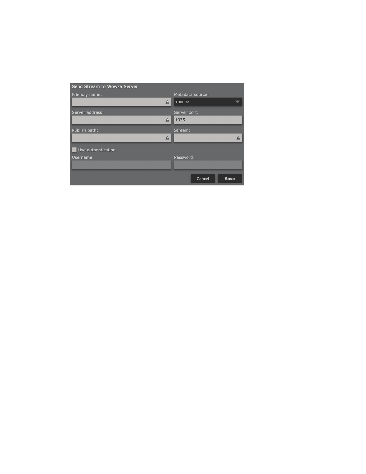
PROCESSING AND ENCODING
Send to Wowza Server
Allows manual configuration of a stream pushed to a Wowza server.
Friendly name
Specify an easy to remember “Friendly” name to identify this stream output in the list of streams that have been
defined (i.e. Kxxx – Wowza Stream).
SECTION 8
| 54
Metadata source
Select a metadata input source to be used with this encoding instance (if desired). See Chapter 10 for more details.
Server address
Enter the IP address of the Wowza server.
Server port
Enter the port of the Wowza server. The default is 1935.
Publish path
Enter the path to the desired streaming application on your Wowza server (live, for example).
Stream
Enter the name of the stream you wish to create on your Wowza server. This stream will be created under the
specified path (application).
Use Authentication
Check this box to use authentication when sending a stream to the Wowza server. Authentication for RTMP
publisher sources such as R/2 is enabled by default in Wowza and will likely need to be enabled here as well.
Username
Enter the username specified as a publisher in the Wowza server.
Password
Enter the password associated with the publisher username in the Wowza server.
When finished, click “Save” to save and return to the “MP3 Encoder” screen or click “Cancel” to cancel any
changes.
Page 66
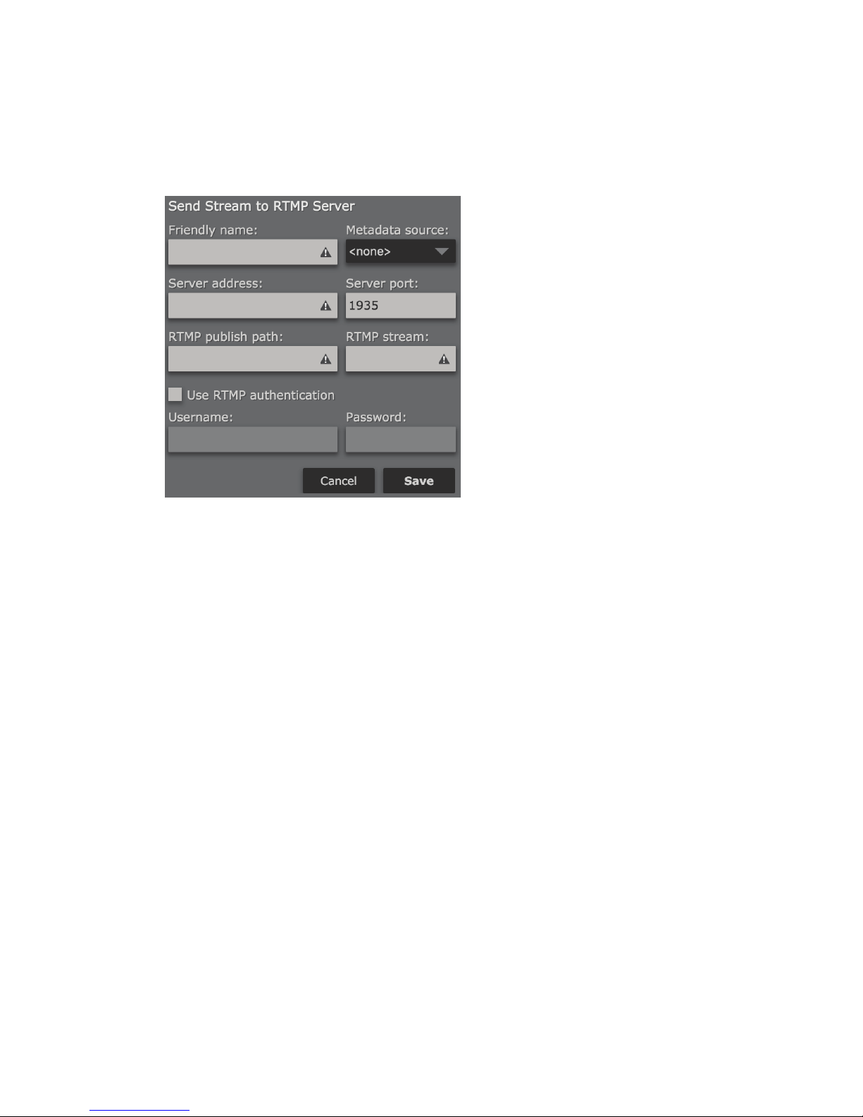
PROCESSING AND ENCODING
Send to RTMP Server
SECTION 8
| 55
RTMP (Real Time Messaging Protocol) is a TCP-based protocol initially developed by Macromedia to deliver
streams to the Flash player. The specification is now available (albeit in incomplete form) for public use. A number
of servers support the RTMP protocol, including Adobe Flash Media Server, Wowza and others.
Friendly name
Specify an easy to remember “Friendly” name to identify this stream output in the list of streams that have been
defined (i.e. Kxxx – RTMP Stream).
Metadata source
Select a metadata input source to be used with this encoding instance (if desired). See Chapter 10 for more details.
Server address
Enter the IP address of the RTMP server.
Server port
Enter the port of the RTMP server. The default is 1935.
RTMP Publish path
Enter the publishing path for the RTMP server—generally provided by your CDN, and may also be referred to as an
“entry point”.
RTMP Stream
Enter the name of the RTMP stream name. The stream name may be fixed or chosen, it depends on your CDN.
Some providers, such as Akamai, require the stream name to be very specific, and they provide the format that
must be used.
Use RTMP Authentication
Check this box to use authentication when sending a stream to the RTMP server.
Username
Enter the username for encoding to your RTMP server.
Page 67
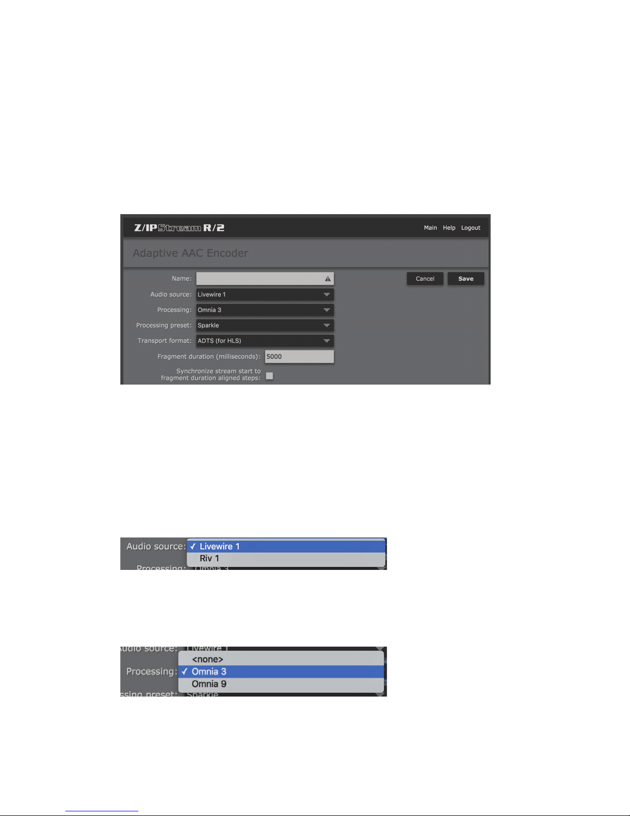
PROCESSING AND ENCODING
Password
Enter the password for encoding to your RTMP server.
When finished, click “Save” to save and return to the “MP3 Encoder” screen or click “Cancel” to cancel any
changes.
Adaptive AAC Encoder
SECTION 8
| 56
As more audio content is being streamed to mobile devices, adaptive encoders take on increased importance. An
adaptive encoder sends an audio stream in multiple bitrates to the server. The client device then automatically
chooses the best one based on available bandwidth. As more or less bandwidth becomes available, the mobile
device may request higher or lower bitrate audio, so it is able to adapt to network conditions dynamically.
Name
Enter a “friendly name” for this encoder instance to easily identify it for status and control from the main “control
panel” screen (i.e. Kxxx-Adaptive Stream 1).
Audio Source
Select one of the previously defined audio sources as the input to this processing instance (see Chapter 7). Note
that these sources can be used in multiple processing or encoding instances simultaneously.
Processing
Selects between Omnia 3 and optional Omnia.9 processing (or no processing at all, should you simply want to
route audio through this instance without processing). Up to 8 channels of Omnia.9 processing can be licensed per
R/2. When you have reached the maximum number of Omnia.9 licenses available (or if Omnia.9 processing is not
licensed) this option will not be displayed. See Chapter 16 for more information on Omnia.9 processing.
Page 68
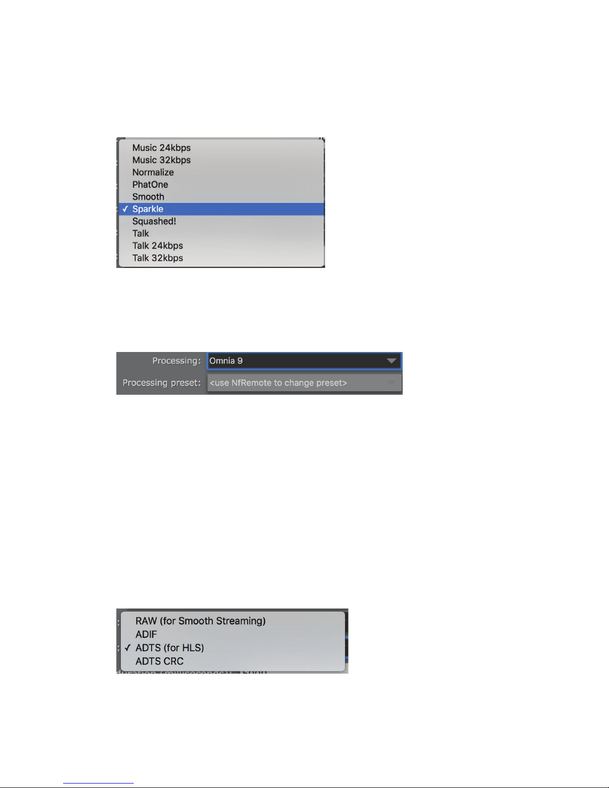
PROCESSING AND ENCODING
Processing preset
Selects the processing preset to be used for this instance. When Omnia 3 processing is selected, the list of available
presets will appear. These presets are not format specific, though there are bitrate specific presets for “Music” and
“Talk”. Experiment with various presets to find one that works best for your programming format and application.
Presets can be copied and modified to create a sound customized exactly to your needs. See Chapter 9 to learn how
to “fine tune” the Omnia 3 processing, and Chapter 13 for more information on Omnia 3 preset management.
SECTION 8
| 57
If optional Omnia.9 processing is enabled, the preset must be selected via NfRemote software due to the powerful
processing tools and test instrumentation available through Omnia.9. See Chapter 16 for more details.
Fragment duration (milliseconds)
Configures the fragment length. Adaptive streaming splits audio into fragments which are then (usually by HTTP)
downloaded by the client device. The longer the fragments, the more latency in the stream as the player will need to
keep at least one fragment buffered before downloading the next one
Synchronize stream start to fragment duration aligned steps
This setting will synchronize fragment start between primary and backup servers. This option should be used
together with an RTP source using absolute PTP time so adaptive streams will be started only on fragment length
boundaries and fragments from primary and backup servers will be synchronized. If only one encoder server is
being used, then this option should be left unchecked.
Transport Format
Select the desired transport format for this Adaptive AAC Encoding Instance. This will depend on the server platform and application. Multiple streams and bitrates can be defined in a single Adaptive AAC instance as necessary.
Page 69
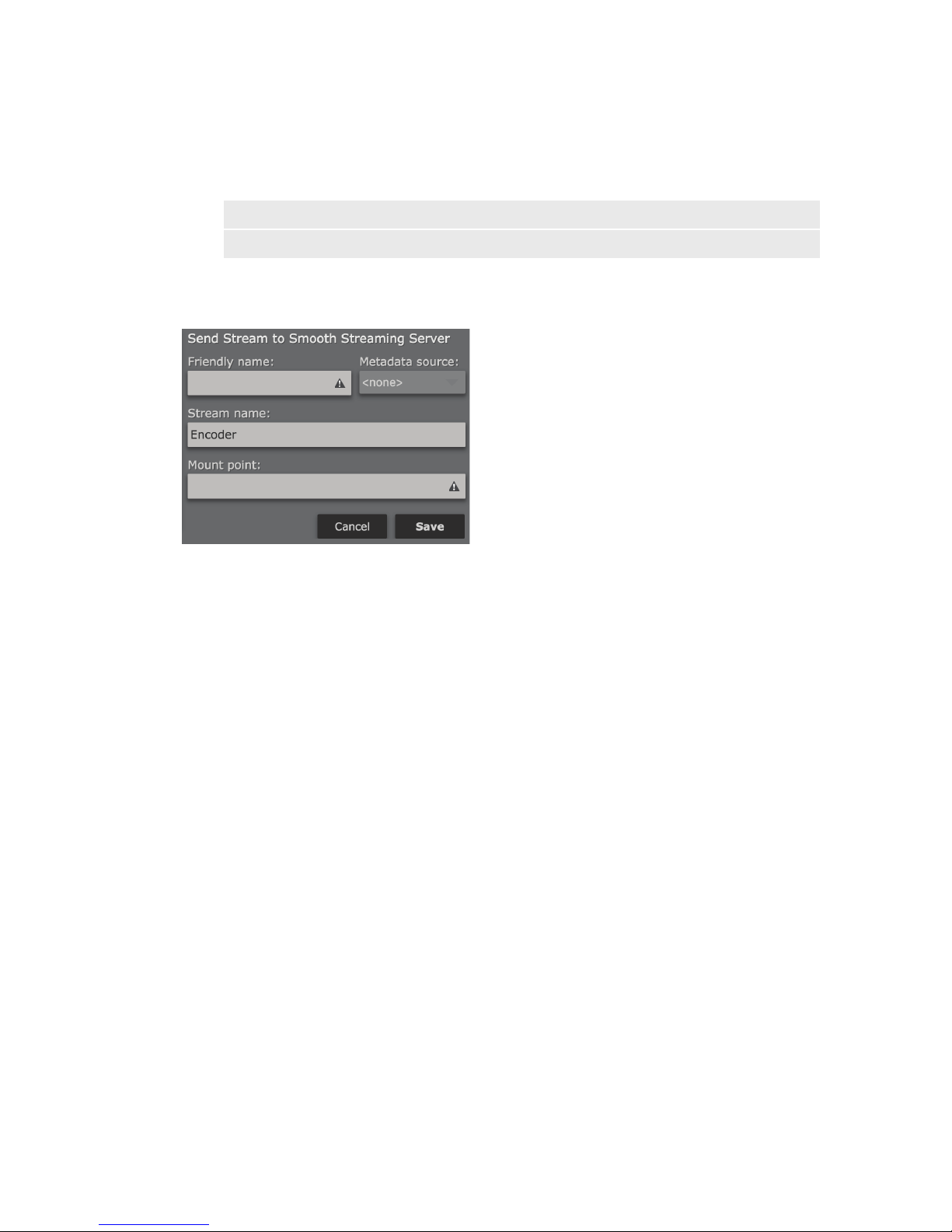
PROCESSING AND ENCODING
Note:
ADIF and ADTS CRC should NOT be used with Smooth Streaming or HLS unless there are very
specic server requirements.
RAW (for Smooth Streaming)
Smooth Streaming is an IIS Media Services extension that facilitates adaptive streaming to clients via HTTP. SDKs
are available from Microsoft to enable Smooth Streaming over Silverlight and Windows Phone 7. It may also be
ported to Apple iOS, Android and Linux
SECTION 8
| 58
Friendly name
Specify an easy to remember “Friendly” name to identify this stream output in the list of streams that have been
defined (i.e. Kxxx – Adaptive Stream).
Metadata source
Metadata is not yet available for Smooth Streaming but should be available for custom CDN servers in the future.
Stream Name
If multiple streams use the same mount point, then Stream Name can be used to separate them. The default Stream
Name is “Encoder”.
Mount point
Each Smooth Streaming server may contain multiple broadcasts (or mount points) each containing a separate
stream of content. Thus, ‘mount point’ is just a unique name that identifies a particular stream. The mount point
needs to be configured properly in order for the stream to work. Mount point names should not contain any spaces
or odd characters.
When finished, click “Save” to save and return to the “Adaptive AAC Encoder” screen or click “Cancel” to cancel
any changes.
Page 70
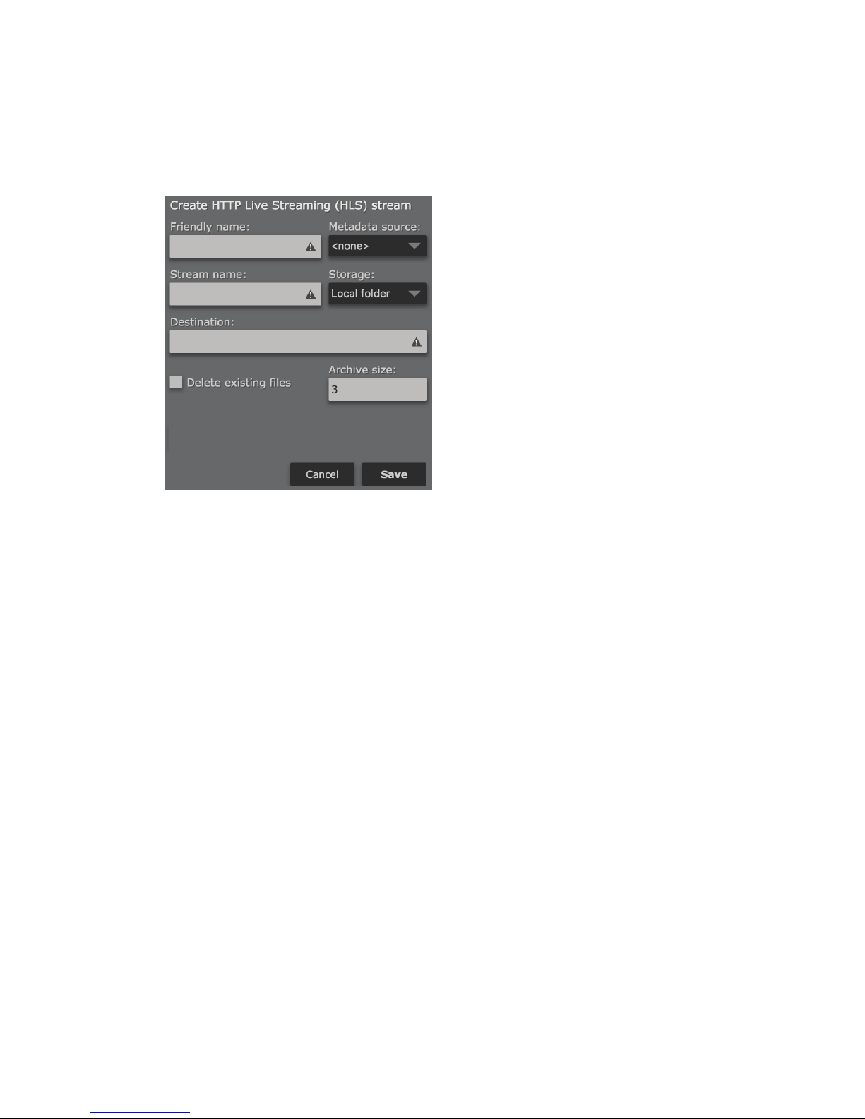
PROCESSING AND ENCODING
ADTS (for HLS)
Apple’s HTTP Live Streaming protocol allows you to create multiple bitrate adaptive streams, which allow the
client’s device to request the needed bitrate stream depending on the available network bandwidth.
SECTION 8
| 59
Friendly name
Specify an easy to remember “Friendly” name to identify this stream output in the list of streams that have been
defined (i.e. Kxxx – HLS Stream).
Metadata source
Select a metadata input source to be used with this encoding instance (if desired). See Chapter 10 for more details.
Stream name
This name will be used in HLS filenames and folders. Please use only letters, numbers, dashes and underscores.
Storage
Select “Local Folder” or “FTP Server”. The “Local Folder” setting will make files available via an HTTP share on R/2
in the format: http://r2address/streams/HLS/streamname/streamname.m3u8
Destination
When set to “FTP Server”, this field specifies the FTP server where HLS file chunks should be uploaded. This field
requires a full FTP path i.e. “ftp://user:password@hostname:21/folder/” to specify a username, password, and
port, or “ftp://hostname/folder/” if no authentication or port number is needed. If the HLS stream is transferred
to an FTP server, the server must have its own web service to serve the files to the listeners.
Delete existing files
Removes all files from the folder or FTP server when the stream is started. Use this option with caution as the files
will be permanently deleted!
Archive size
Set number of fragments that need to be stored. The old fragments will be deleted. If this variable is set to 0, all the
fragments will be stored.
When finished, click “Save” to save and return to the “Adaptive AAC Encoder” screen or click “Cancel” to cancel
any changes.
Page 71
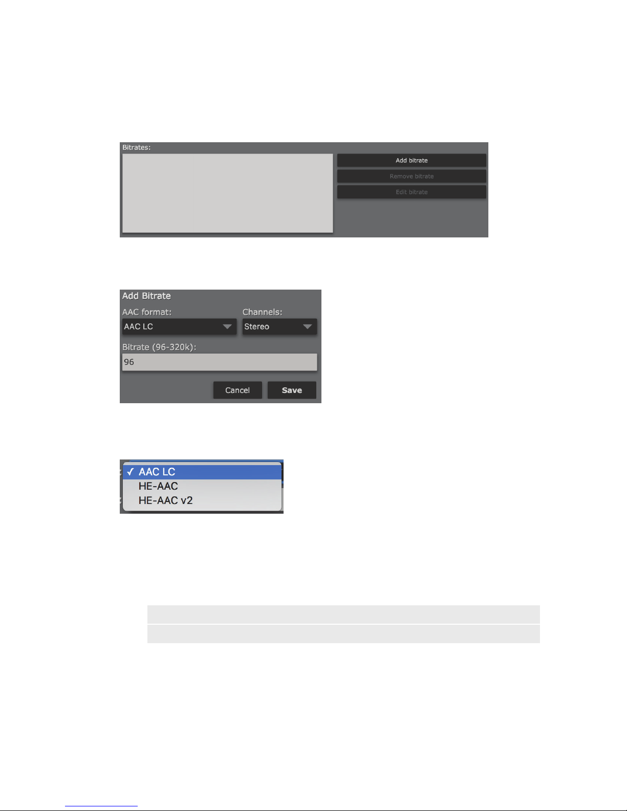
PROCESSING AND ENCODING
Configuring Available Bitrates
In addition to defining the other adaptive streaming parameters, you will need to configure the bitrates and AAC
encoding formats contained in those streams.
SECTION 8
| 60
Click “Add bitrate” to add an entry to the list.
AAC Format
There are several different “flavors” of AAC. The most common form (and the default for this instance) is AAC-LC
(Advanced Audio Coding-Low Complexity). HE-AAC is “High Efficiency” AAC. It is designed for bitrates between
24 and 96 kbps. An “improved” version of HE-AAC (HE-AAC v2) was developed for lower bitrates between 14 and
56 kbps. HE-AAC v2 also offers improved stereo performance at lower bitrates. It is worth noting while HE-AAC v2
is widely supported, it may not be compatible with some players.
Note:
If in doubt, choose AAC-LC. This is the most common form of AAC encoding, though the HE (High
Eciency) variants are becoming more common for lower bitrate applications.
Page 72
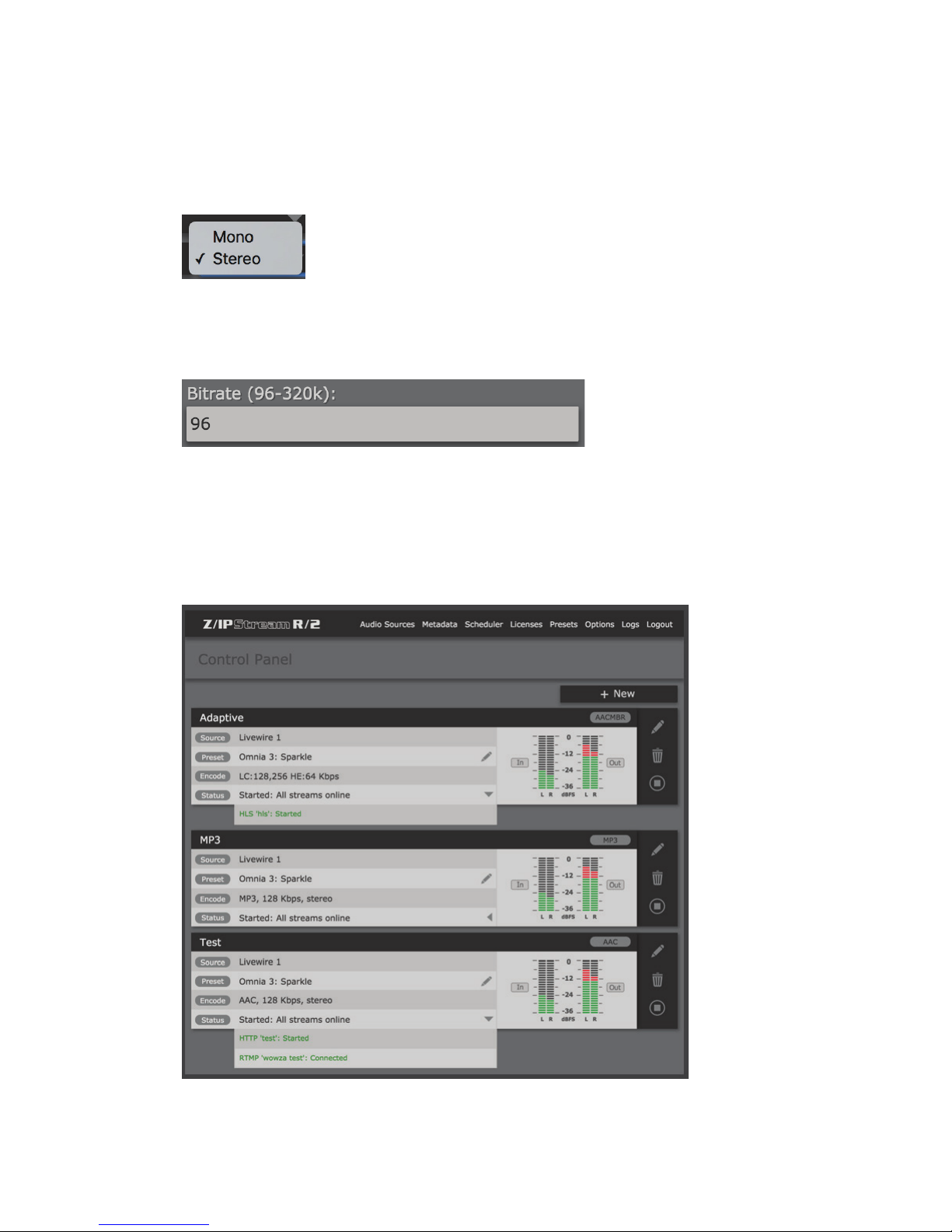
PROCESSING AND ENCODING
Channels
Select whether this stream will be encoded in Mono or Stereo. Mono should provide a mono sum of the incoming
audio. This setting will be locked to stereo for HE-AAC v2.
Bitrate
Enter the bitrate for this stream. The valid bitrate range will change depending on which AAC format is selected.
When finished, click “Save” to save and return to the “Adaptive AAC Encoder” screen or click “Cancel” to cancel
any changes.
SECTION 8
| 61
Managing Processing and Encoding Instances
Page 73
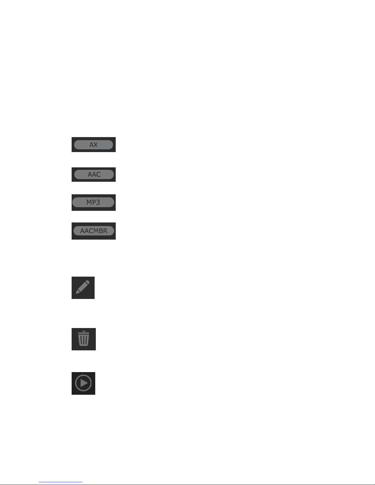
PROCESSING AND ENCODING
Click “Main” or the Z/IPStream R/2 logo to return to the main “Control Panel” screen. All processing and encoding
instances that have been defined will be displayed, along with their configured parameters and status. Click the
“triangle” on the “Status” line to display additional details about the individual streams contained within each
instance.
Instance Type
The oval at the top right of each instance will display the type of instance that has been defined.
Indicates an audio processing instance
Indicates a standard AAC encoding instance
Indicates an MP3 encoding instance
SECTION 8
| 62
Indicates a multiple bitrate (adaptive) AAC encoding instance
Instance Controls
Edit the parameters of an instance. Some parameters may not be changed once an instance has been defined, or
while an instance is running.
Delete an instance. This is a permanent action. Deleted instances cannot be recovered and will need to be re-created.
Starts an instance that is currently stopped. Instances that are not currently running will be “greyed out”.
Page 74

PROCESSING AND ENCODING
Stops an instance that is currently started.
Metering and Processing Control
I/O Metering is provided for each instance. Audio processing presets for each instance can be modified by clicking
the “pencil” icon next to the preset name (see Chapter 9 for more details on Omnia 3 processing). Instances using
Omnia.9 processing can be accessed via NfRemote for more detailed monitoring and control of the audio processing
(see Chapter 16).
SECTION 8
| 63
Page 75
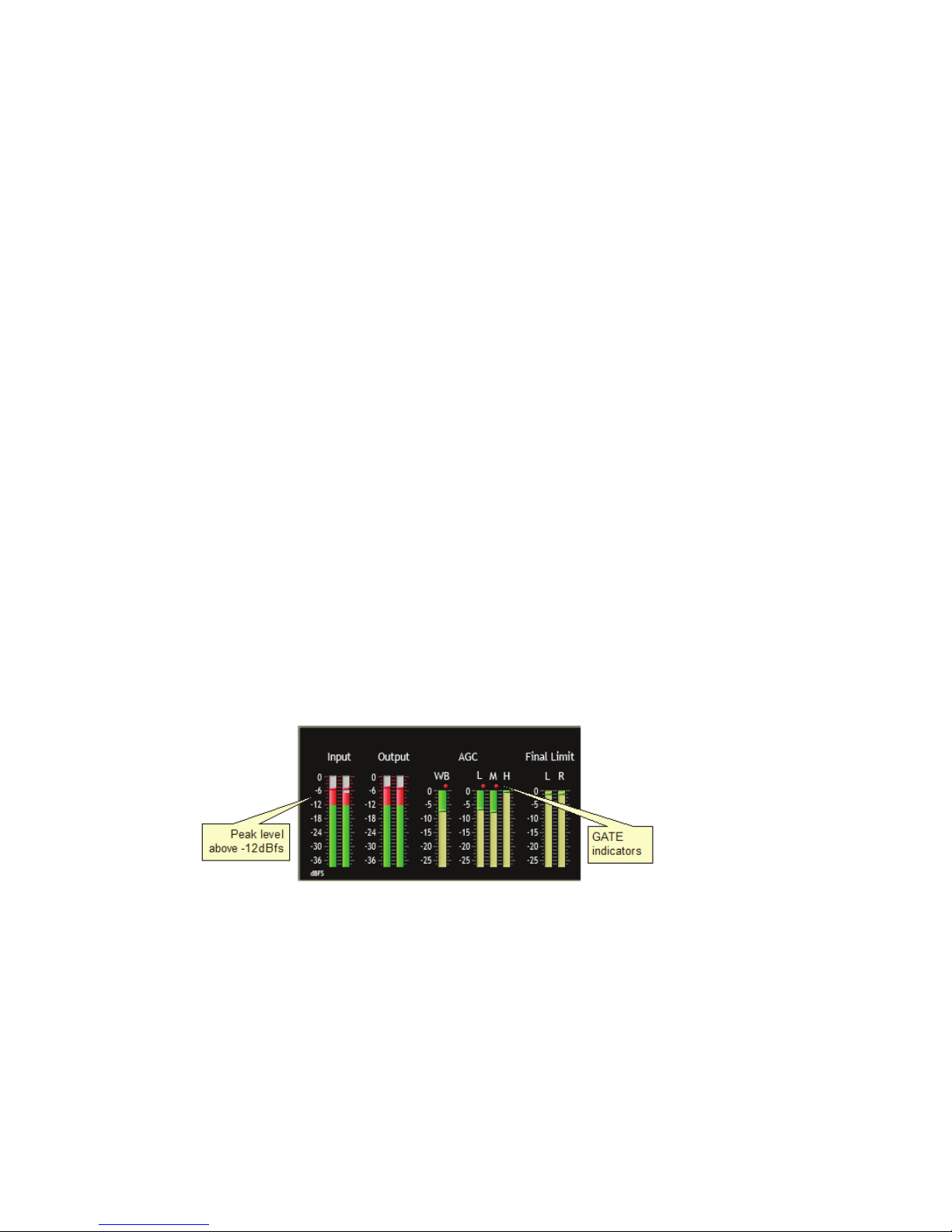
9 Omnia 3 Processing Setup
Overview
Standard audio processing for Z/IPStream R/2 is the Omnia 3-band processor. Omnia 3 is intuitive and easy to use.
Applying audio will activate movement on the bar graphs, and this is confirmation that processing is occurring.
All audio processing adjustments are performed in the Preset Editor. A “preset” is simply a large table of values
representing all of the control values for every control listed in the menu tree. When you choose a preset, the
control values are loaded into the processing structure, reconfiguring Omnia 3.
We recommend exploring the provided factory presets. Then, once you find the preset that most closely matches
the sound you’re after, you can customize it to your liking. More information about Omnia 3 preset management
can be found in Chapter 13 of this manual.
Understanding the Omnia 3 Bar Graphs and Indicators
The bar graphs are capable of indicating more than just level information. The texture and density of the audio
signal can be observed, based upon the dynamic action of the bar graphs, and peak-responding “pills”. Of interest
are the “pills” at the end of the input and output meters, as they indicate peak level. The bar section represents the
RMS average of the signal. Wide dynamic range will display a separation between the pills and the bar, whereas
signal with little peak information will cause the pills to ride on the crest of the bar graph. The bar graphs can
indicate up to 25 dB of gain reduction.
SECTION 9
| 64
The bar graphs provide a wealth of information about the processing control in Omnia 3. The algorithms automatically adapt the style of compression/limiting control being employed on a moment-by-moment basis. This
can be deduced if the metering is studied over time. During normal operation, the indicators will have a dynamic
“bounce” that you will be able to get a feel for. Every now and then, you will see the processor react quickly and
show a larger amount of gain reduction. Notice that the response is very fast. This action will recover very slowly,
and return to “rest” with the main bar graph. This action will be easily noticed on material that is very dynamic in
texture. More on this below.
Another feature unique to Omnia 3 is processor “Hold”. During brief pauses in audio, the bar graphs will “freeze”
and the GATE indicators will show the processor has entered the Hold mode of the algorithm. This is most easily
noticed when there is a “dry” voice being processed.
The Input/Output level meters will change from green to red whenever the level exceeds –12dBfs. The pills also
change color on the Input/Output displays. In the dynamic processing section, the pills maintain the same color.
Page 76
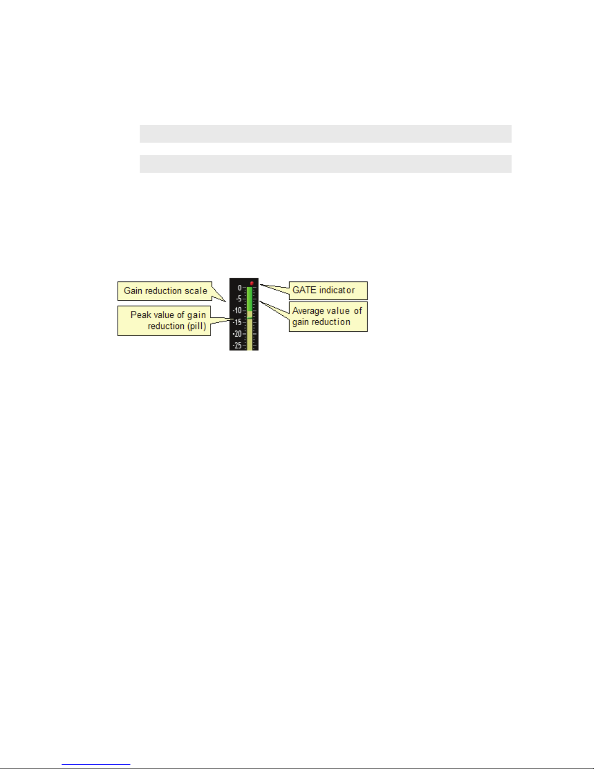
OMNIA 3 PROCESSING SETUP
Note:
The input and output levels are displayed relative to 0dB full scale (0dBfs). The 0 indicator on the input/output bar graphs means that every available bit of signal level is being used at that time! There
is nothing more in the level department, except to create distortion… nasty sounding distortion!
Interpreting the Gain Reduction Meter Displays
Through careful observation of the processing bar graphs, significant information can be acquired and analyzed
about the audio signal on a moment-by-moment basis. The bar shows the average value of the gain reduction, while
the floating pill indicates the peak value of gain reduction.
SECTION 9
| 65
Since the processing algorithms in Omnia 3 ‘adapt’ to the audio, it is capable of performing many different
processing functions at different times. The processing display bar graphs may appear to indicate different kinds
of operation with different program material. This behavior is primarily based on dynamic range differences in the
applied program material. For program material that is already processed or lacking dynamic range, the bar graphs
will indicate differently than with material that possesses a high degree of dynamic range. This is because audio
signals that lack dynamic range, naturally or by previous processing, will possess a lower peak to average ratio.
Conversely, audio signals with a wide dynamic range possess a higher peak to average ratio. The Omnia 3 adapts
differently to each case.
For program material that has low dynamic range (or high RMS and low peak levels), there will be more activity in
the WB-AGC sections and less activity in the Multiband Processors. This behavior is due to the WB-AGC response
to high RMS energy, while the Multiband section is reacting to lower peak energy. Sometimes the Multiband
section may not indicate any action at all. For Omnia 3, this is completely normal! Examples of this behavior might
be seen with heavily processed commercials or music, or with music passages of sustained level. A good example
is the Aerosmith album “Pump.” This recording has very little dynamic range. Try any up-tempo selection from
this recording and you will see the Wideband-AGC section make initial adjustments along with small amounts of
limiting. Once adjusted, the Wideband-AGC section will stay deep in gain reduction, although with little movement, and action within the limiters will be minimal.
When the programming has wide dynamic range (low RMS and high peak levels), the opposite will occur. The
Multiband section becomes active, while the WB-AGC section will appear not to respond as much. During these
events, the Multiband sections could be working aggressively, while the WB-AGC section indicates little activity.
Good examples of programming able to cause this behavior: vocal passages, live voice, classical music, and passages
with high transient levels. Good test examples: almost anything classical, as well as almost anything by Steely Dan!
Also keep in mind that the WB-AGC section is designed to operate much more slowly than the Multiband sections,
primarily because of the nature of each function. Remember that the WB-AGC section operates on the program’s
RMS energy. During gain calculations, the incoming program’s “average” level is established, and gain adjustments, if needed, are made based on those calculations. This is why the WB-AGC sections will appear to move
slower as it makes changes over relatively long time periods.
Page 77
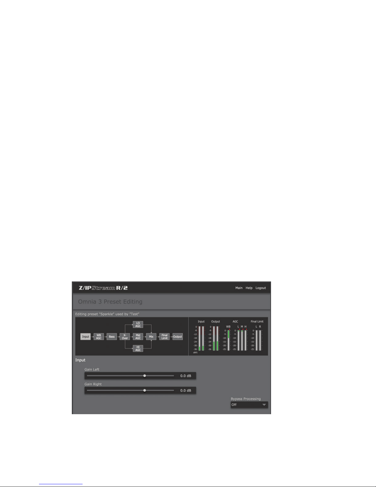
OMNIA 3 PROCESSING SETUP
The intent of the Multiband section is to normalize the spectral balance and provide control of the peak levels.
Peak energy must be detected and adjusted in a quick and accurate manner while, at the same time, not interfering
with the sonic integrity of the audio signal. For this reason, the Multiband sections operate faster, with special
background instructions to govern their behavior, and strictly on an as-needed basis.
Since the processing displays are capable of providing a wide range of information, we do not recommend setting
up the system based on any specified meter indications. Instead, we recommend setting up the processing by using
your ears to judge the sound. We’ve provided the meters only to analyze the signals and aid you in adjusting the
specific parameters needed to achieve your desired sonic results. Like a speedometer, the meters are a guide, not
the road!
The red ticks that appear above the WB (Wideband AGC), L (Low-Band AGC), M (Mid- Band AGC), and
H (High-Band AGC) bar graphs are the GATE indicators. They display GATE activity. The GATE function is
described above in the section titled “Understanding the Bar graphs and Indicators”
Editing Presets
Once a at least processing or processing/encoding instance has been defined, you are ready to begin the editing
process. From the main “Control Panel” screen, click on the pencil icon to the right of the preset name in the
desired instance, and you will be presented with a block diagram of the Omnia 3’s audio path. Clicking on any of
the blocks takes you to the controls available for that section. Once you’ve made your adjustments, click Save or
Cancel, depending on whether or not you like what you hear.
SECTION 9
| 66
Input
Clicking on the Input block displays the input section sub-menu. There are adjustments for the individual Left/
Right channels. Drag the slider-bar to adjust the respective level. There is a 30dB range of adjustment between
–20dB and +10dB.
Using normal program audio, a correct gain setting results in peak indications (the“bouncing balls”) hitting -12
dBFS (where the level meters turn red) or a little higher. This corresponds to system headroom of 12 dB. You may
adjust for more headroom if you wish (lower indications), but setting the input level for less headroom (higher
meter indications) is strongly frowned upon.
Page 78
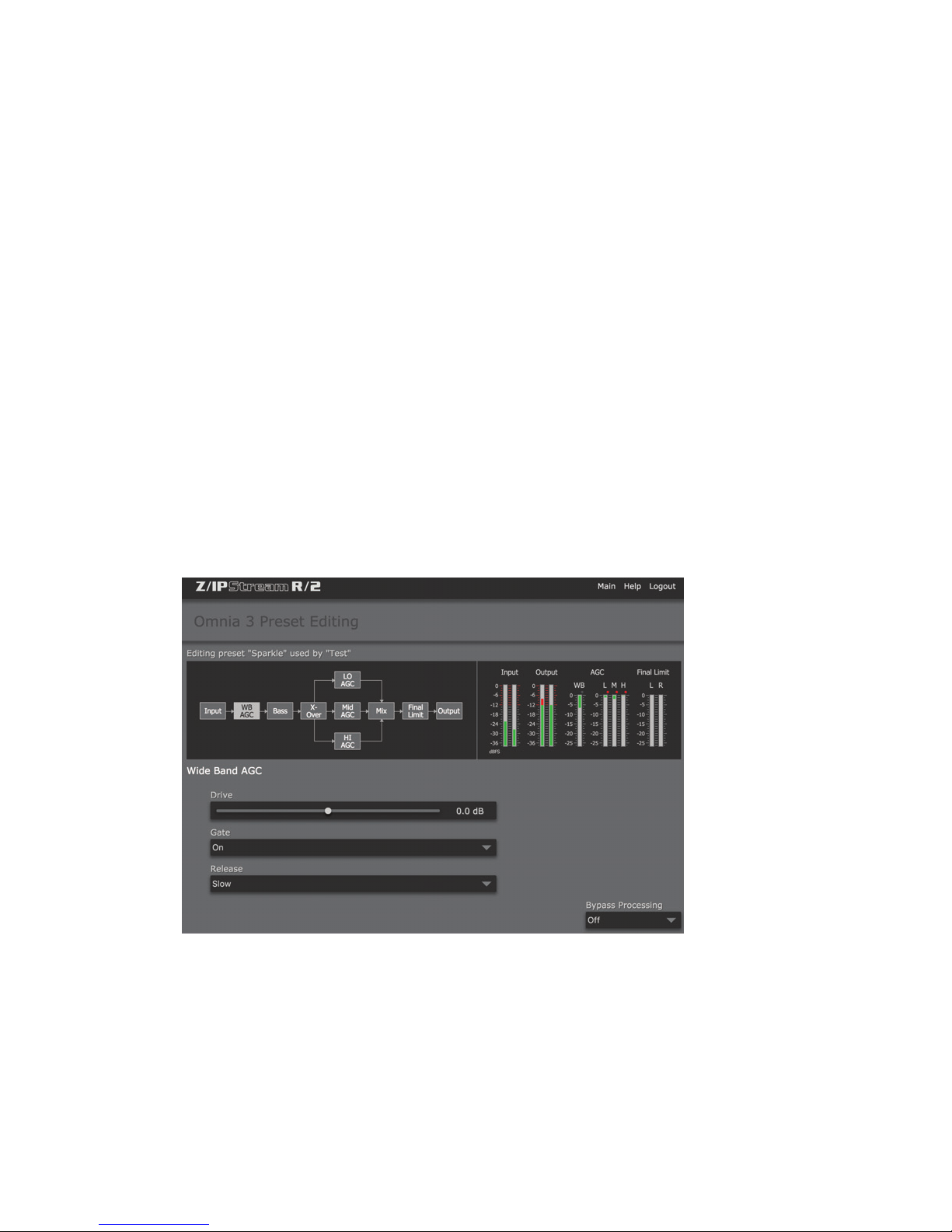
OMNIA 3 PROCESSING SETUP
Wide Band AGC
A very flexible wideband leveler section provides smooth, transparent control of the input program. This is
achieved through two significant Omnia innovations: a dual referenced release gate and a hidden, intelligent
“makeup” gain algorithm. The dual gate reference is a unique process that correlates the dynamics of the audio
input signal to a “rolling” reference level, and from that information makes conditional decisions affecting the
character of the release function.
A hidden, Make-Up Gain, control signal determines when the amplitude of the input program suddenly falls
to a reduced level. It then adjusts the side chain gain in order to “fill in” the softer program passages so that the
average level is increased. This allows the AGC function to operate with slower time constants, while significantly
increasing the average audio level. These slower overall time constants yield lower intermodulation distortion,
contributing to Omnia’s trademark sound.
Using Classical music for an example, the orchestra often plays forte, and then enters abruptly into a quiet passage.
Conventional AGC algorithms would hold the softer passage down until it was able to slowly recover at the static
release time setting, making such passages nearly inaudible at normal listening levels. Omnia 3’s makeup gain
function allows a hidden, faster time constant to provide quick recovery, but only during the softer passage. As
soon as the orchestra starts to play louder, the “makeup” time constant yields control back to the primary AGC
circuit, returning gain to the previous platform level. This sophistication preserves the dynamic integrity of the
signal while greatly enhancing the listenability of the program.
SECTION 9
| 67
This is the first processing section within the Omnia 3, so the controls in this section affect the overall signal, its
density, and hence affect every other processing section following it. The job of the Wideband AGC is to erase
long-term audio level fluctuations, while doing so in a very unobtrusive manner. This sub-menu provides a few
parameters that tailor the action of this section.
Page 79
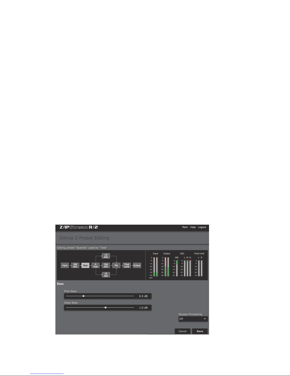
OMNIA 3 PROCESSING SETUP
Drive
The sets the audio level that enters the WB-AGC. Increasing the Drive will produce more compression. This control
is calibrated between –6dB and +6dB, and adjusts the signal level into the Wideband AGC. It should be adjusted
to net approximately 12dB of gain reduction with typical programming. Too little gain reduction can defeat the
“leveling” function of the Wideband AGC. Too much gain reduction has little additional benefit. Nominal gain
reduction values for the Wideband AGC are between 10 and 15dB.
Gate
When set to ON, it will freeze the gain at the last level of processing action that occurred before the audio signal fell
below the threshold of operation. This control helps to minimize “pumping”, and the increase of background noise
during pauses in programming.
Release
Controls the speed of recovery for any given amount of gain reduction. Faster action yields less dynamic range and
the presence of more density to the audio. The Release control sets the time constants in relative terms using Slow,
Medium, and Fast. Because the time constants are program-dependent, calibrating these controls in absolute time
values (ms/dB) would be useless—therefore we use simple terminology.
Clicking Save after adjusting any of the parameters in this section will save the change and close the sub-menu.
SECTION 9
| 68
Bass
This section contains the Bass EQ controls. In the the unique Omnia 3 signal processing architecture, these
controls are placed in their optimal position — just before the multiband processor sections. Each of the Deep Bass
and Phat Bass controls can boost the level up to 12 dB. Be careful here not to overdrive the following sections or
over emphasize these lower frequency ranges. When used properly this specialized low frequency enhancement
tools can deliver the thunderous bass and warmth that the Omnia is known for, and it can do so without making the
sound muddy.
Page 80
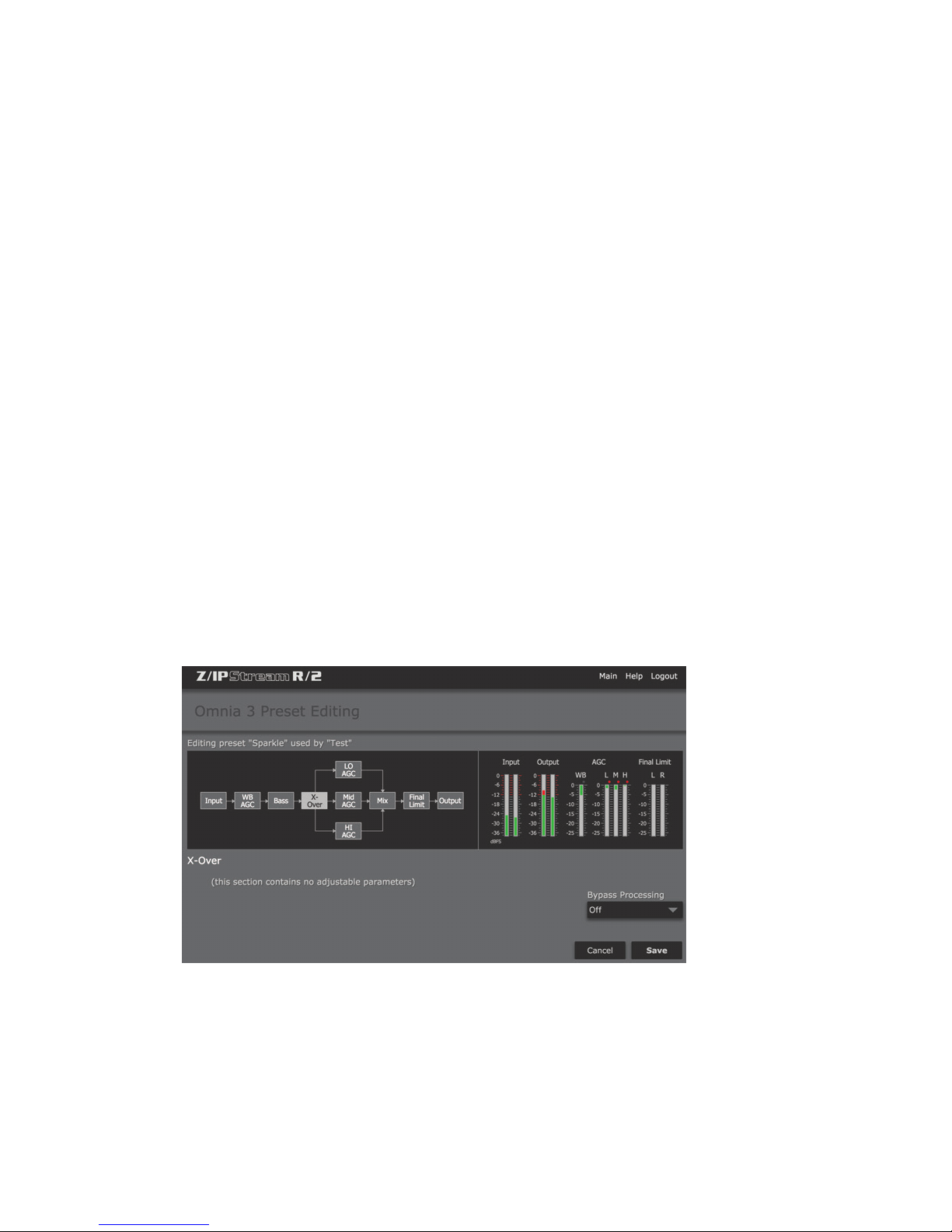
OMNIA 3 PROCESSING SETUP
Phat Bass
A unique enhancement that adds filtered harmonics of the lower registers to the upper bass frequencies. The
algorithm extracts information contained in the initial attack to do its work, and low frequency texture is therefore
emphasized. Older recordings sound fuller (or phatter) with the added illusion of loudness. Phat Bass EQ also
helps devices with small speakers sound like they have more bass than they actually do. A little of this effect goes
a long way so be careful not to apply too much boost. Be sure to listen on several different types of both fixed and
mobile media devices to arrive at a setting that works best for all of them.
Deep Bass
For those who demand thunderous bass, the Omnia 3 has it! Up to 6 dB of “thunder” can be dialed in. And we’re
not talking about a simple bass boost, but a rather sophisticated concept that takes into consideration the time
alignment of the low frequencies as they pass through the entire Omnia system. It allows a loud, clean low end,
with absolutely no sacrifice to the overall loudness of your signal. We won’t tell you where the control is in the
signal chain. But we will tell you that Deep Bass function is a shelf boost at 90 Hz, utilizing a phase compensated
12dB/octave slope to emulate the EQ function.
X-over
This section contains no adjustable parameters, but here’s a bit of information about why we did what we did. Most
multiband audio processors make a compromise in the crossover area in order to provide a flat dynamic frequency
response. This is done to avoid audible peaks or dips in the recombined frequency response as the individual band
gains change during processing. In an effort to minimize this problem, most processors use a fixed phase-offset in
the crossovers. While such treatment helps to minimize frequency response peaks and dips, it also results in a loss
of phase linearity, usually causing an increase in “smearing”, as well as reducing musical clarity.
SECTION 9
| 69
In Omnia 3’s implementation, the crossover network is carefully time-aligned so that the recombined spectrum
remains flat, regardless of the amount of gain control being applied within any band. This true phase linear
response assures that harmonic overtones are not displaced in time. The result: the truer, more natural, and more
musical Omnia sound.
Page 81
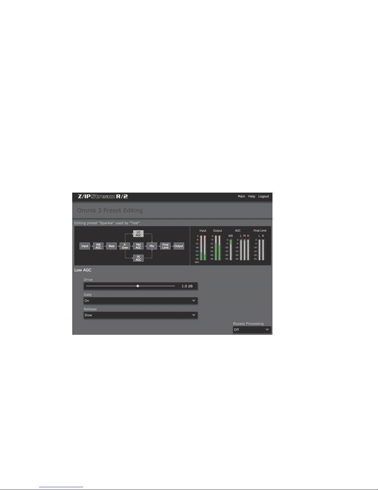
OMNIA 3 PROCESSING SETUP
Multiband AGC Sections
Similar in character to the wideband AGC described above, but expanded to three bands, this section has the ability
to significantly add power and loudness to the audio while tailoring and pre-processing it for delivery to the final
limiter section. The system uses different algorithms for each of the bands: The low and mid bands use a feedback
configuration, which produces a larger, warmer sound on lower frequencies. The high band utilizes a feedforward
design that maintains a more open, natural and musical texture on higher frequencies.
As with any multiband processor, improper adjustment can exaggerate noise at high frequencies, particularly with
older recordings that possess a good deal of tape hiss. This can especially occur if the highest AGC band is driven
so that significant gain reduction occurs, and the band’s gating control is set to the lower end of the scale. During
audio segments that have little or no HF content, the AGC will try to increase its gain in an effort to restore treble
balance. Even during periods when the gate function is in the default Freeze mode, the problem might still exist
with some programming.
Since the user parameters are the same for all three bands, only the LF Band will be detailed here.
SECTION 9
| 70
Drive
Sets the audio level that enters the AGC. Increasing the Drive will produce more compression. This control
is calibrated between –6dB and +6dB, and adjusts the signal level into the AGC. It should be adjusted to net
approximately 12dB of gain reduction with typical programming. Too little gain reduction can defeat the “leveling”
function of the Wideband AGC. Too much gain reduction has little additional benefit. Nominal gain reduction
values for the AGCs are between 10 and 15dB.
Release
Controls the speed of recovery for any given amount of gain reduction. Faster action yields less dynamic range and
the presence of more density to the audio. The Release control sets the time constants in relative terms using Slow,
Medium, and Fast. Because the time constants are program-dependent, calibrating these controls in absolute time
values (ms/dB) would be useless—therefore we use simple terminology.
Page 82
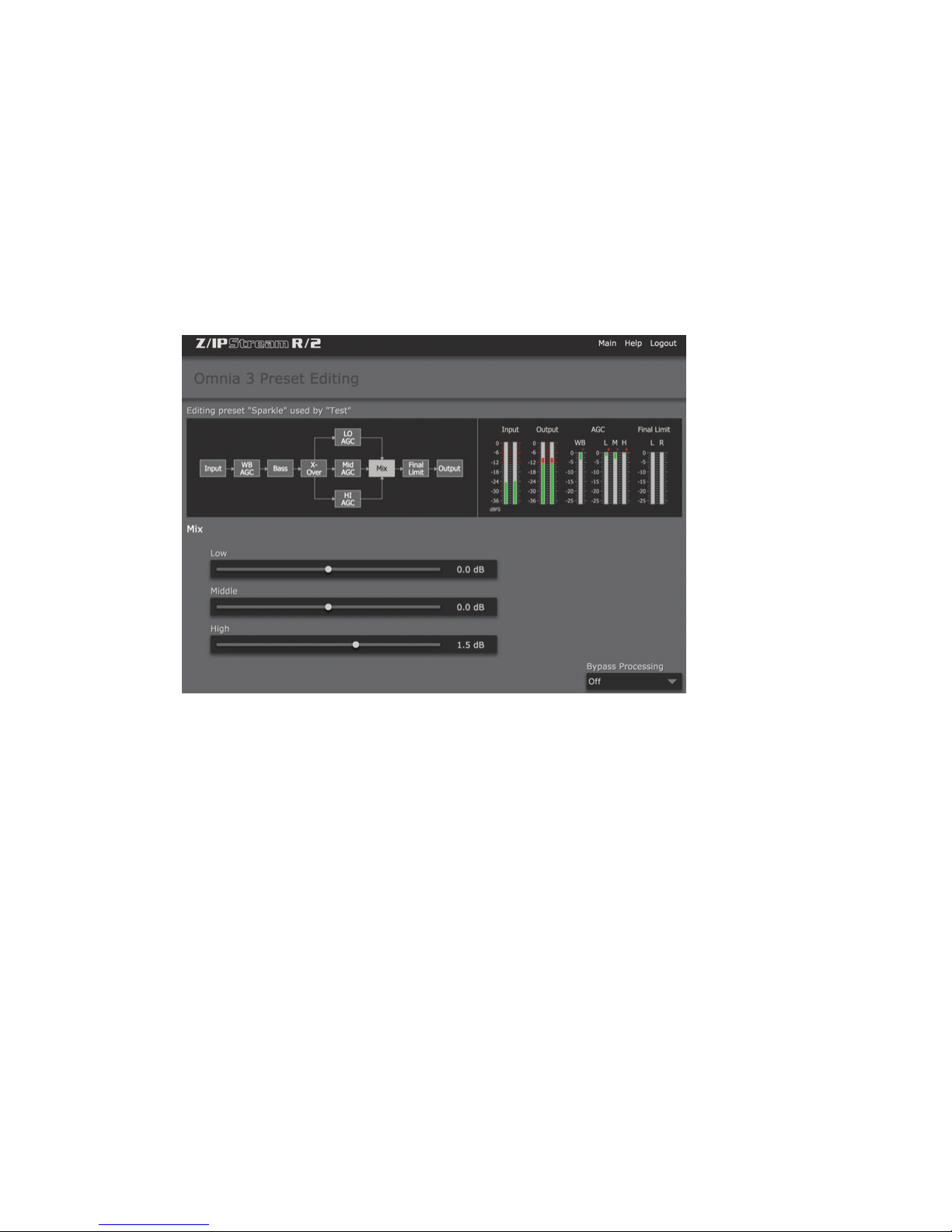
OMNIA 3 PROCESSING SETUP
Gate
When set to ON, it will freeze the gain at the last level of processing action that occurred before the audio signal fell
below the threshold of operation. This control helps to minimize “pumping”, and the increase of background noise
during pauses in programming.
Mix
SECTION 9
| 71
This is where the three multiband processors are mixed together. Use care in adjusting this section, as too much
level from one particular band may cause an excessive amount of emphasis to that range of frequencies. Such adjustment may also drive the final limiter bands in that range of frequencies too hard, causing the sound to become
unnatural, dense, and squashed. As explained earlier, if your desire is to “EQ” the sound, you should perform that
function using the drive levels in the multiband section. The mixer is primarily intended for minor “EQ” changes to
the overall sound. There is a +/-6dB range of adjustment for each band.
Page 83
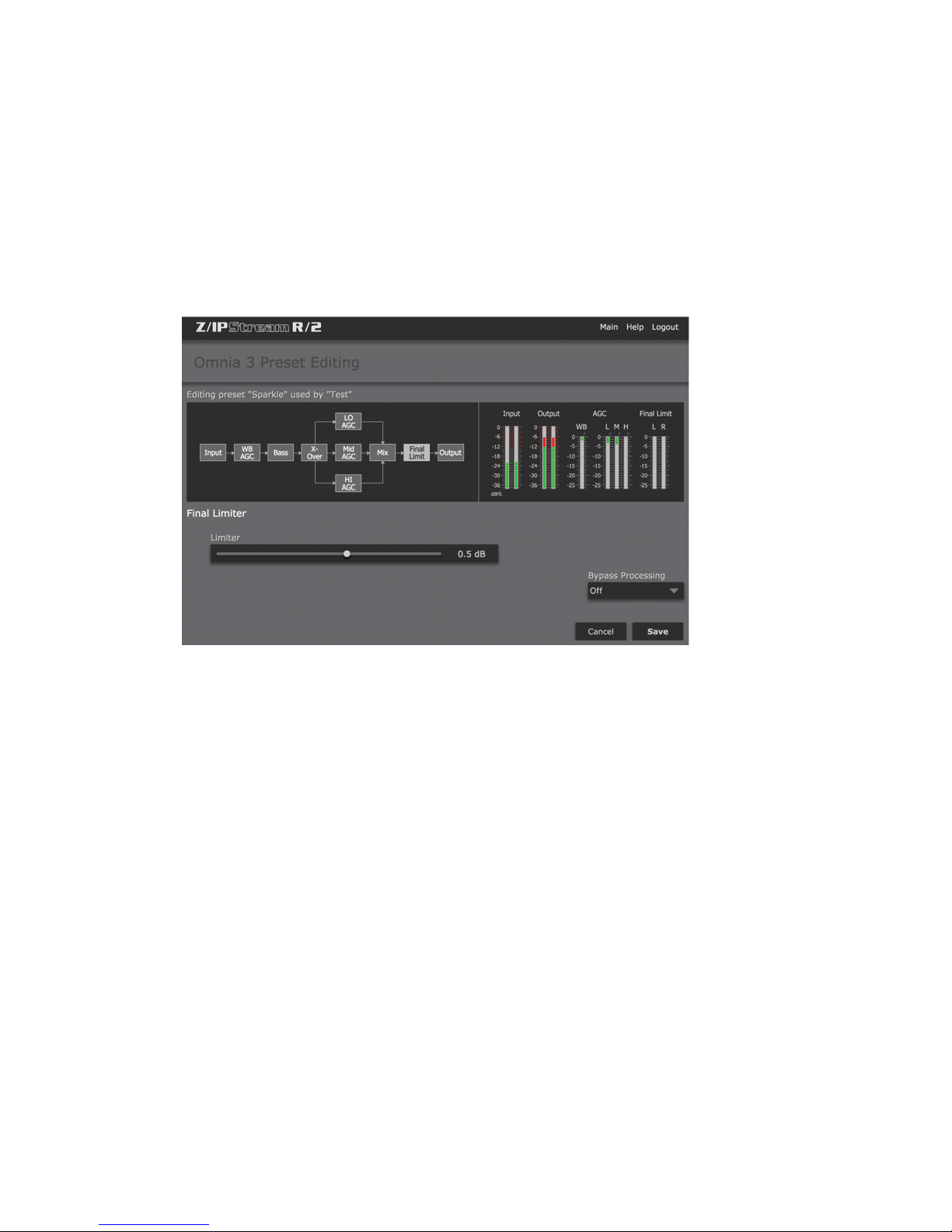
OMNIA 3 PROCESSING SETUP
Final Limiter
Omnia 3 employs a lookahead limiter to provide absolute and precision peak control. This limiter has been
designed to minimize processing side-affects like IMD, which are usually associated with limiters of this type.
Using an innovative design that cancels intermodulation products before they develop, allows this limiter to sound
extremely transparent. The limiting function is derived using numerous control signals that monitor one another.
SECTION 9
| 72
This type of peak controller is used instead of a clipper because it does not generate the same high levels of THD as a
Clipper does. THD causes added difficulties in a coded audio system, as the harmonics generated from the clipping
action, create added artifacts in the encoder. These are especially annoying at high frequencies.
On the other hand, a lookahead limiter, yields extremely low levels of THD, although it will create some IMD
component, and this allows the audio coder to operate with minimal sonic artifacts. There are tradeoffs in how
each of these peak controllers sound when they are set to produce added loudness. When a clipper is pushed, the
audio may appear edgier. This is from the added harmonic content. In contrast, the lookahead limiter will appear
busier, or dense as the action of the control signal may be heard, when more limiting is applied.
Limiter Drive
This is where the loudness versus quality is most evident! This limiter’s adjustment range is +/-3 dB, in 0.1dB steps.
It is advisable to make minor changes, primarily as the “loudness fine tuner”. Be careful, there is a lot of power here!
A little bit goes a long way!
Page 84
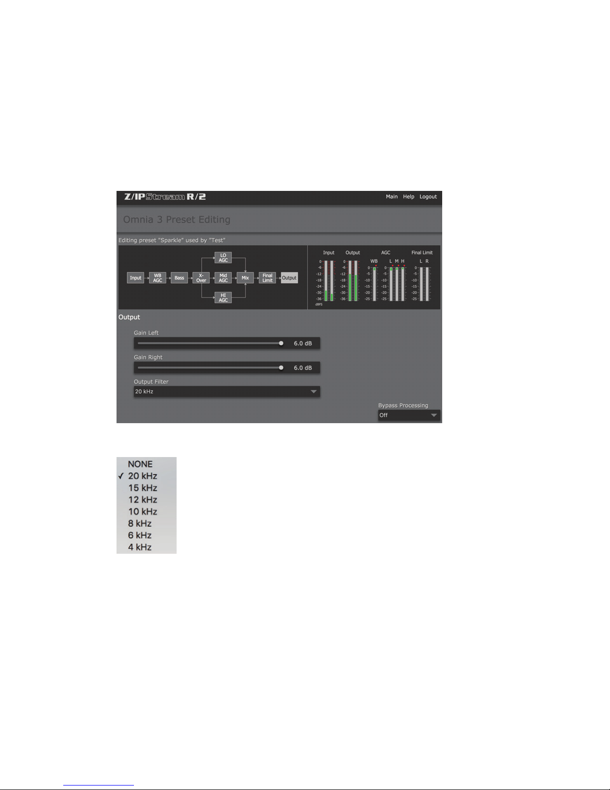
OMNIA 3 PROCESSING SETUP
Output
The peak output level adjustment is done using the individual Left/Right output controls. The control range is from
–26dB to +6dB of gain. This level is normally set to the maximum input level, or just below it, of the device that the
Omnia 3 is connected to.
SECTION 9
| 73
Output Filter
For webcasting applications, especially at lower bitrates, it is sometimes desirable to reduce the audio bandwidth.
This is particularly useful if you are using a low cost sound card to feed and external encoder as the filtering in many
sound cards in inadequate.
A pull-down menu provides eight different filter response curves that can reduce the spectrum down to 4kHz.
Page 85
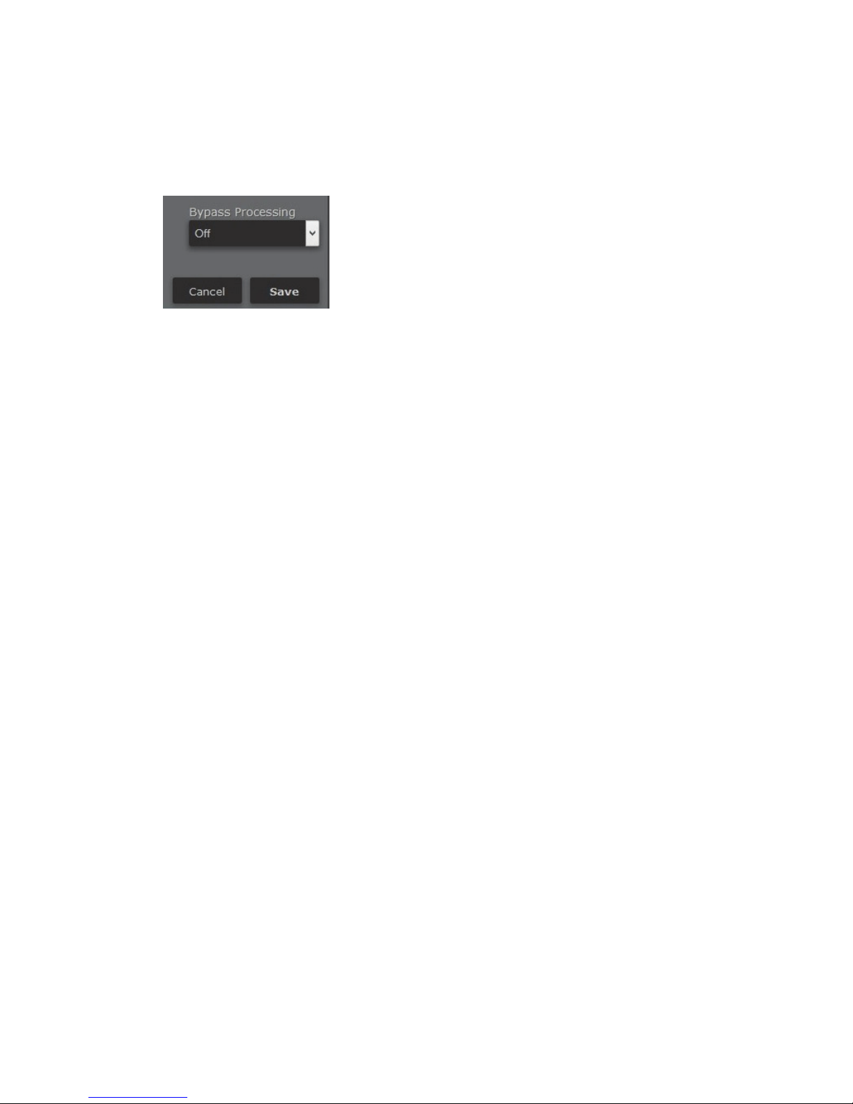
OMNIA 3 PROCESSING SETUP
Bypass
The processing can be bypassed simply by clicking on the BYPASS button located in the lower right hand corner of
the processing panels. This is a simple and fast method to compare the before and after affects of the processing.
To save changes to the current processing preset and return to the main “Control Panel” screen, click “Save”. Click
“Cancel” to return without saving changes.
SECTION 9
| 74
Page 86
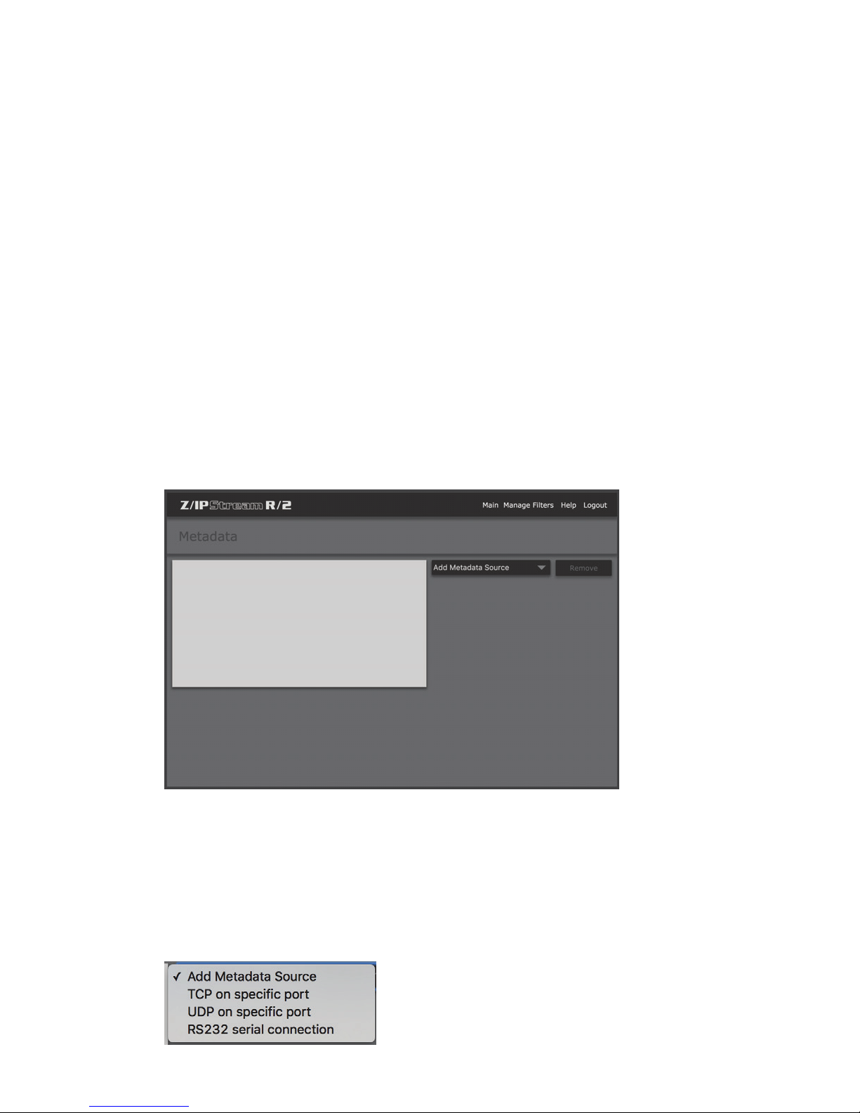
10 Metadata Sources and Filters
Overview
The metadata subsystem gives you the option to tag your audio stream with “now playing” text, album covers and
other graphic information.
The metadata is received from an external system over TCP/IP or UDP, then passed to a metadata filter for parsing.
RS-232 serial metadata will be supported in a future version. Once the filter detects a complete record, it sends the
tagging information to the Stream Sender which includes it in the outgoing stream data.
Metadata Sources
SECTION 10
| 75
From the main “Control Panel” window, click on “Metadata”. The Metadata window allows you to view currently
defined metadata sources, define new ones, and manage metadata “filters”.
After you define metadata sources, they will appear in the metadata dropdown list in the encoder configuration
dialog. Make sure to create the metadata source first, or go back and edit any of your encoders to add metadata
support to the streams.
To add a new metadata source, click on “Add Metadata Source”. Metadata via TCP, or UDP is supported. RS-232
serial is not currently implemented.
Page 87
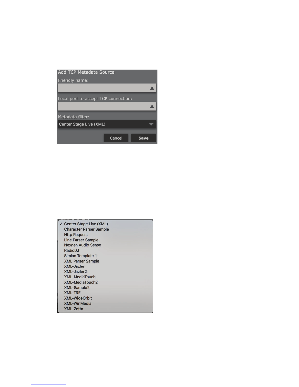
METADATA SOURCES AND FILTERS
TCP on specic port
This selection accepts metadata via a specified TCP port and processes it according to the selected Metadata filter.
Friendly name
Enter an easily identifiable “friendly” name for this metadata source (i.e. Kxxx Automation Metadata).
SECTION 10
| 76
Local port to accept TCP connection
Enter the TCP port number where your automation or metadata management system will connect to send metadata to R/2.
Metadata filter
Select from the list of available “metadata filters”. The factory supplied metadata filters should cover a number of
common applications. Contact technical support for additional information on creating or modifying metadata
filters.
Click Save to save this entry, or Cancel to return to the Metadata screen.
Page 88
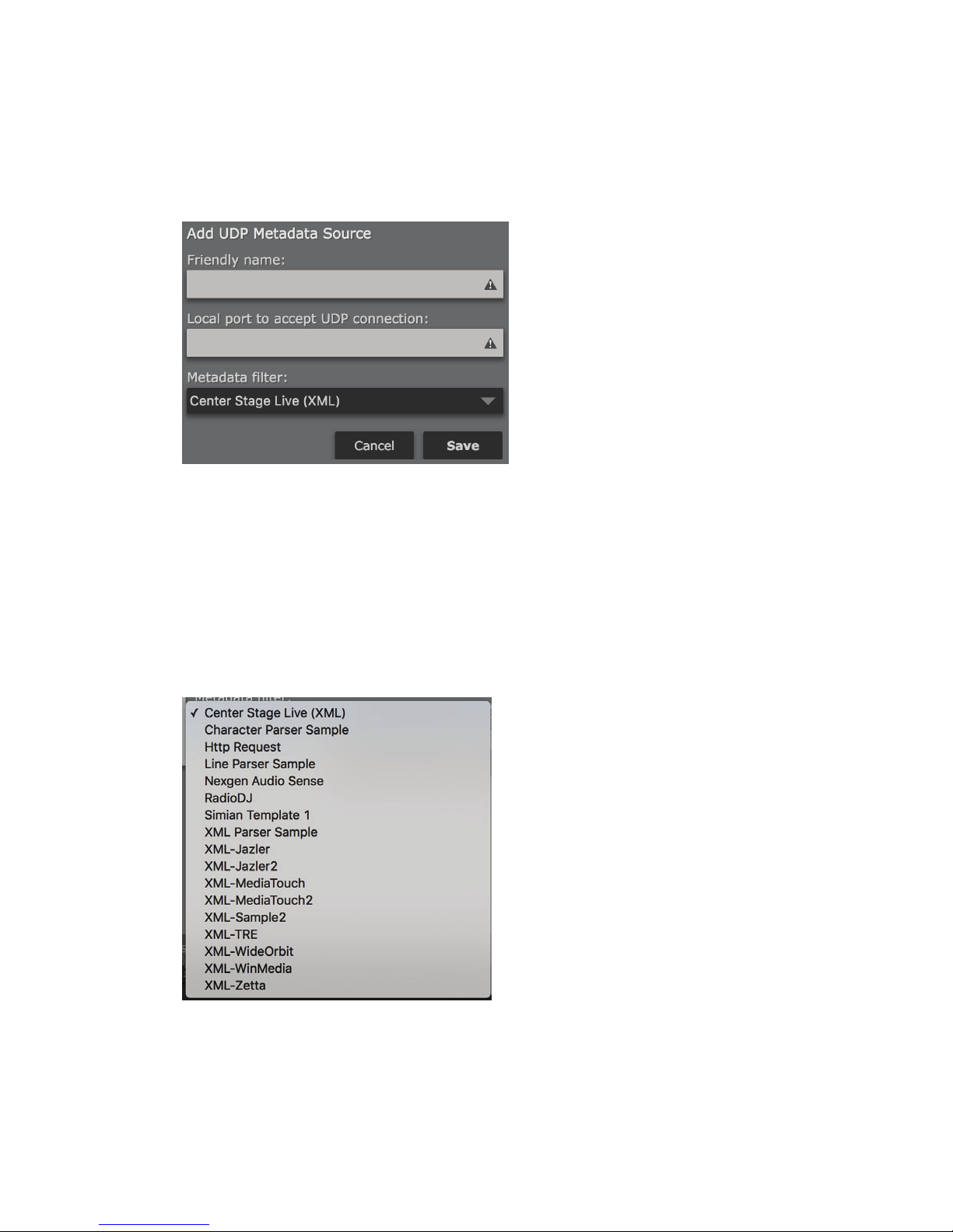
METADATA SOURCES AND FILTERS
UDP on specic port
This selection accepts metadata via a specified UDP port and processes it according to the selected Metadata filter.
Friendly name
Enter an easily identifiable “friendly” name for this metadata source (i.e. Kxxx Automation Metadata).
SECTION 10
| 77
Local port to accept UDP connection
Enter the UDP port number where your automation or metadata management system will connect to send
metadata to R/2.
Metadata filter
Select from the list of available “metadata filters”. The factory supplied metadata filters should cover a number of
common applications. Contact technical support for additional information on creating or modifying metadata
filters.
Click Save to save this entry, or Cancel to return to the Metadata screen.
Page 89
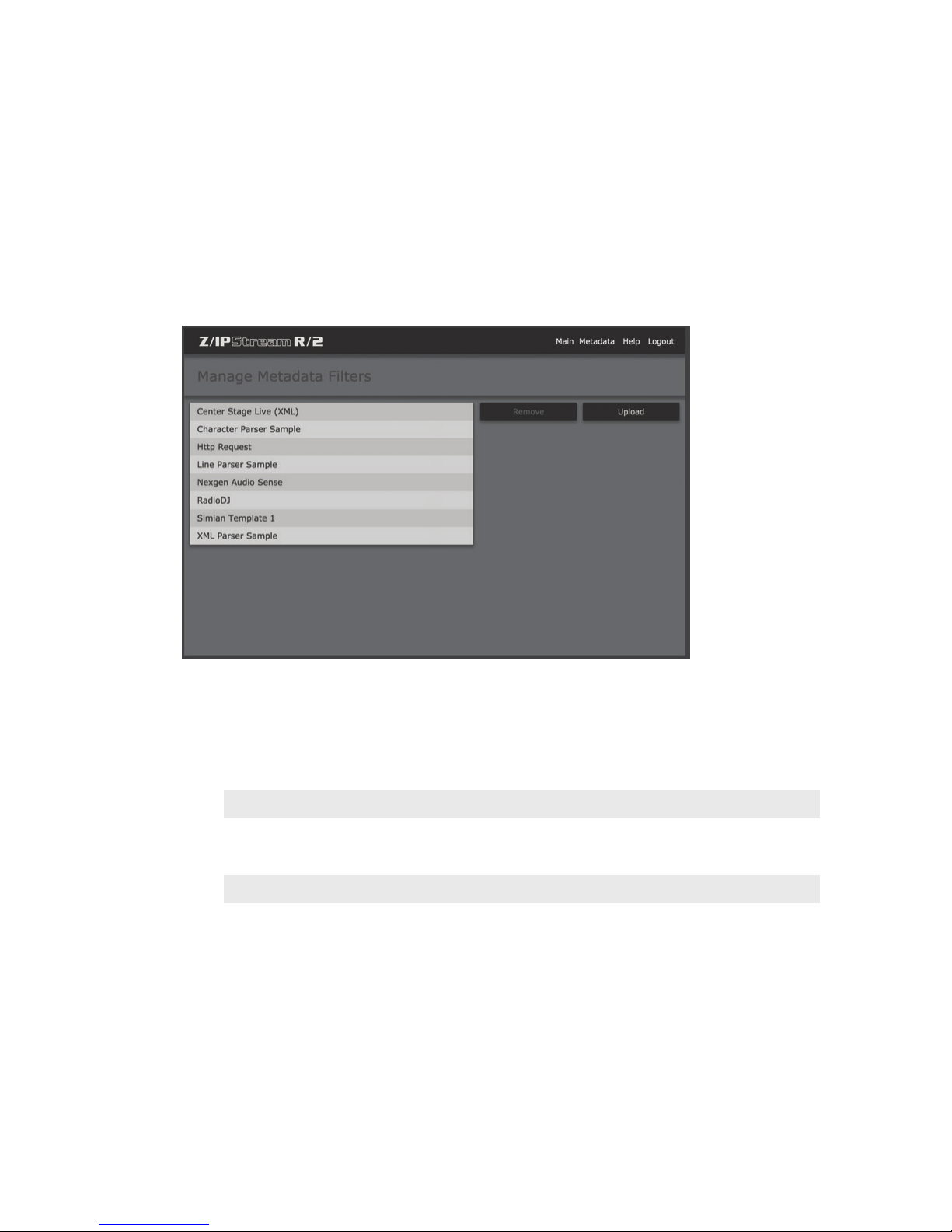
METADATA SOURCES AND FILTERS
Add Serial Metadata source
RS-232 serial metadata is not currently implemented in R/2.
Click Save to save this entry, or Cancel to return to the Metadata screen.
Manage Filters
SECTION 10
| 78
R/2 is extremely flexible and can accept stream metadata from a number of different sources using metadata
“filters”. These filters define the format of the incoming data and reformat it accordingly for stream now playing
information. The “Manage Filters” screen allows you to delete existing filters, or upload new metadata filters to
R/2.
TECH NOTE:
Metadata “lters” are small mini-programs that translate the data received from an external source
to tags that the stream sender can understand. Each lter is a separate le stored on R/2. These
mini-programs are written using the Lua programming language. Technical Support can assist with
developing custom metadata lters. You can nd out more about the Lua programming language at
http://www.lua.org.
Page 90
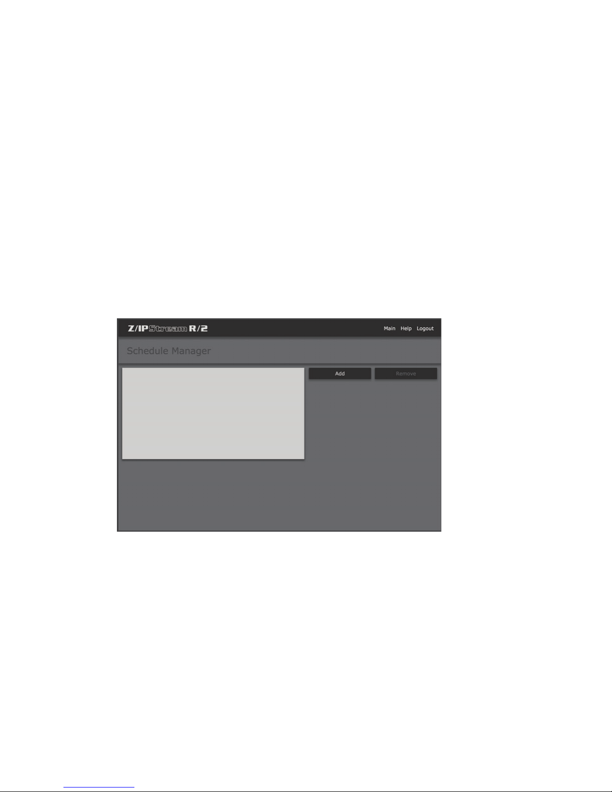
11 Event Scheduler
Overview
The scheduler is able to start, stop audio processor instances or encoders and change an instance’s processing
preset at specified times. This is useful if you want to encode and stream only certain shows. If you need to process
one show differently than another, you can use the scheduler to change audio processing presets.
Schedule Manager
SECTION 11
| 79
Click “Scheduler” from the main “Control Panel” screen to access the Schedule Manager.
The Schedule Events list displays all the events you have created so far. When you select an event from the list, the
event commands are displayed in the Commands area. Click the “Add...” button to create a new event.
Page 91
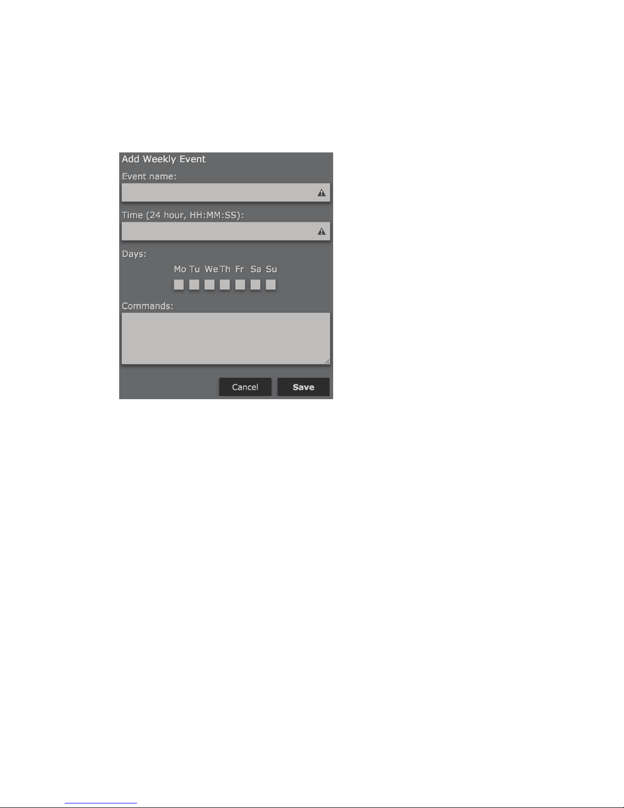
EVENT SCHEDULER
Add Weekly Event
SECTION 11
| 80
Event Name
Enter a name for the event. Keep the names descriptive but use only letters, digits, underscore and space characters.
Do not use other special characters.
Time (24 hour, HH:MM:SS)
Enter the time for the event (in 24-hour, HH:MM:SS format)
Days
Click the check boxes for the days of the week when the event should be active.
Commands
The scheduler works by executing commands you enter in the Commands text box. As of program version 1.01.29,
R/2 recognizes the following commands:
InstanceStart(“ instance_name”)
Use this command to start the instance named instance_name.
InstanceStop(“instance_name”)
This command will stop the instance named instance_name.
Page 92

EVENT SCHEDULER
InstanceLoadPreset(“instance_name”,”preset_name”)
Use this command to load the preset named preset_name into the instance named instance_name.
You may add multiple commands by entering each command on a separate line. For example, you could start an
instance then load a certain preset for it. Or you could start or stop multiple instances at the same time.
Click “Cancel” to cancel and return to the scheduler window, or click “Save” to save changes and return. The newly
added event should appear in the list.
SECTION 11
| 81
Page 93
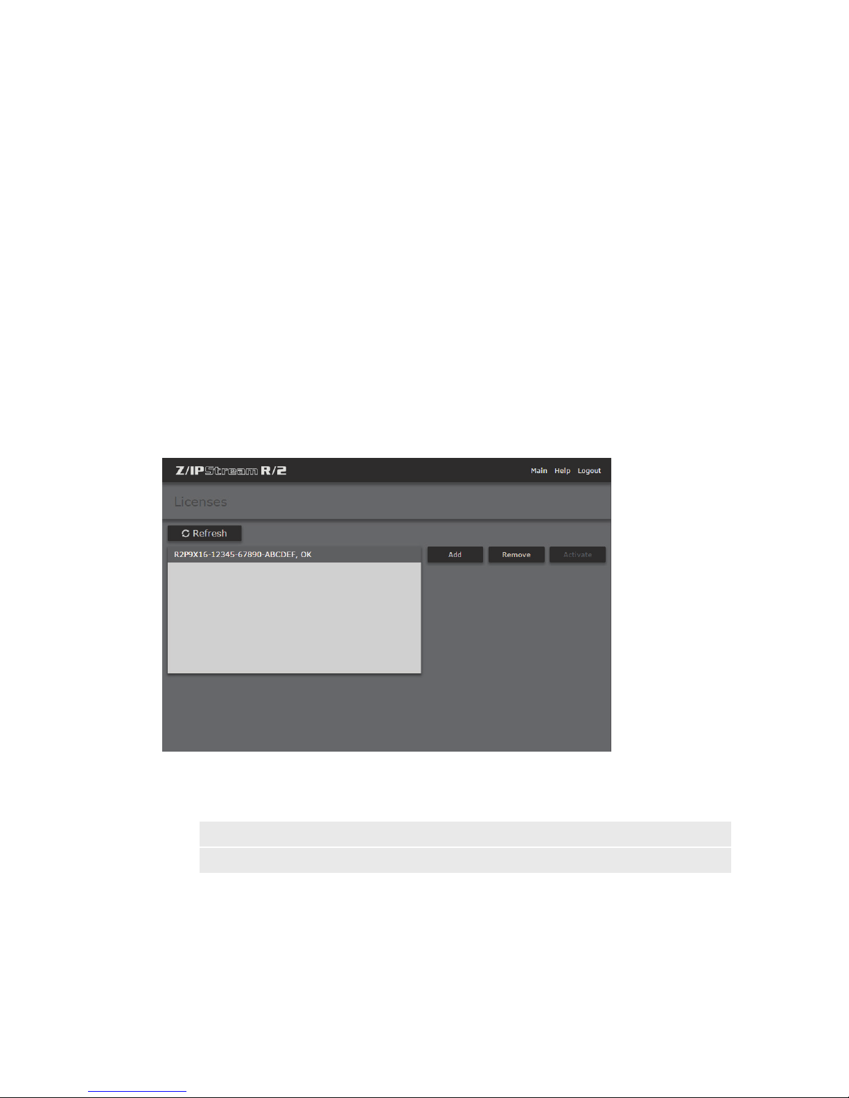
12 License Management
Overview
The licenses determine the number of audio inputs that can be created in R/2, and the type of audio processing
available. R/2 should come licensed from the factory for the configuration that was ordered, but in some cases
it may be necessary to enter additional license keys. Examples would be adding additional audio channels, or
enabling Omnia.9 processing.
Licenses
SECTION 12
| 82
Displays the current license key(s) on the system. Click “Add” to add a new license key.
NOTE:
Licenses are veried with a Telos licensing server. Make sure R/2 is connected to the Internet when
you enter the license codes.
Page 94
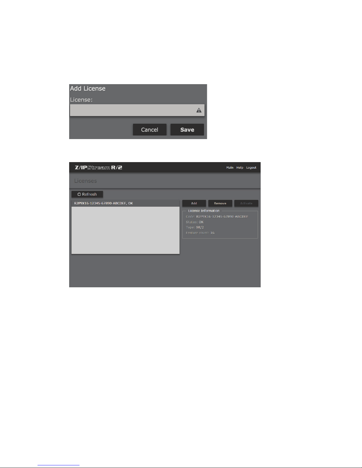
LICENSE MANAGEMENT
Add…
Enter the license key. Click “Save” to save or “Cancel” to return to the Licenses screen without adding the license key.
SECTION 12
| 83
The code you entered will appear in the Licenses list on the left. Next to the license code, you will see additional
text describing the state of the license. The text will initially say “Pending activation”. After 10-15 seconds it should
change to “OK”. To reload the license status, use the “Refresh” button. Add each license code you have received
individually. If all license codes have an “OK” status, then they are active and the additional features (audio
channels or Omnia.9 processing) may be used. See Chapter 7 for configuring additional audio sources, Chapter
8 for configuring processing/encoding instances (including Omnia.9 if licensed) and Chapter 16 for configuring
Omnia.9 processing.
If you see an error message next to the license code, please check the license string to make sure it matches the one
you received. If the error is “Activation failed”, or similar, then contact customer support at+1 (216) 6220247or[email protected]to learn how to activate your license manually.
Page 95
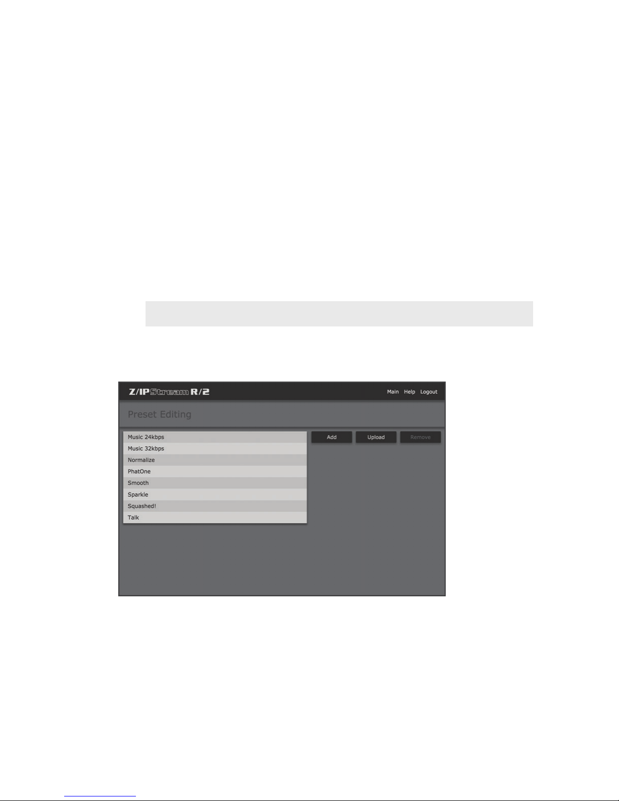
13 Omnia 3 Preset Management
Overview
R/2 is equipped with Omnia 3 processing on all audio channels. The “Presets” screen allows creating new presets
and managing existing Omnia 3 presets on the system. More information on editing Omnia 3 processing and
presets can be found in Chapter 9.
Note:
Omnia.9 presets are managed through NfRemote software (see Chapter 16).
Preset Editing
SECTION 13
| 84
Click “Add” to create a new preset based on an existing factory preset, or click “Upload” to upload a compatible
preset file. See Chapter 9 for more details on modifying Omnia 3 processing.
Page 96
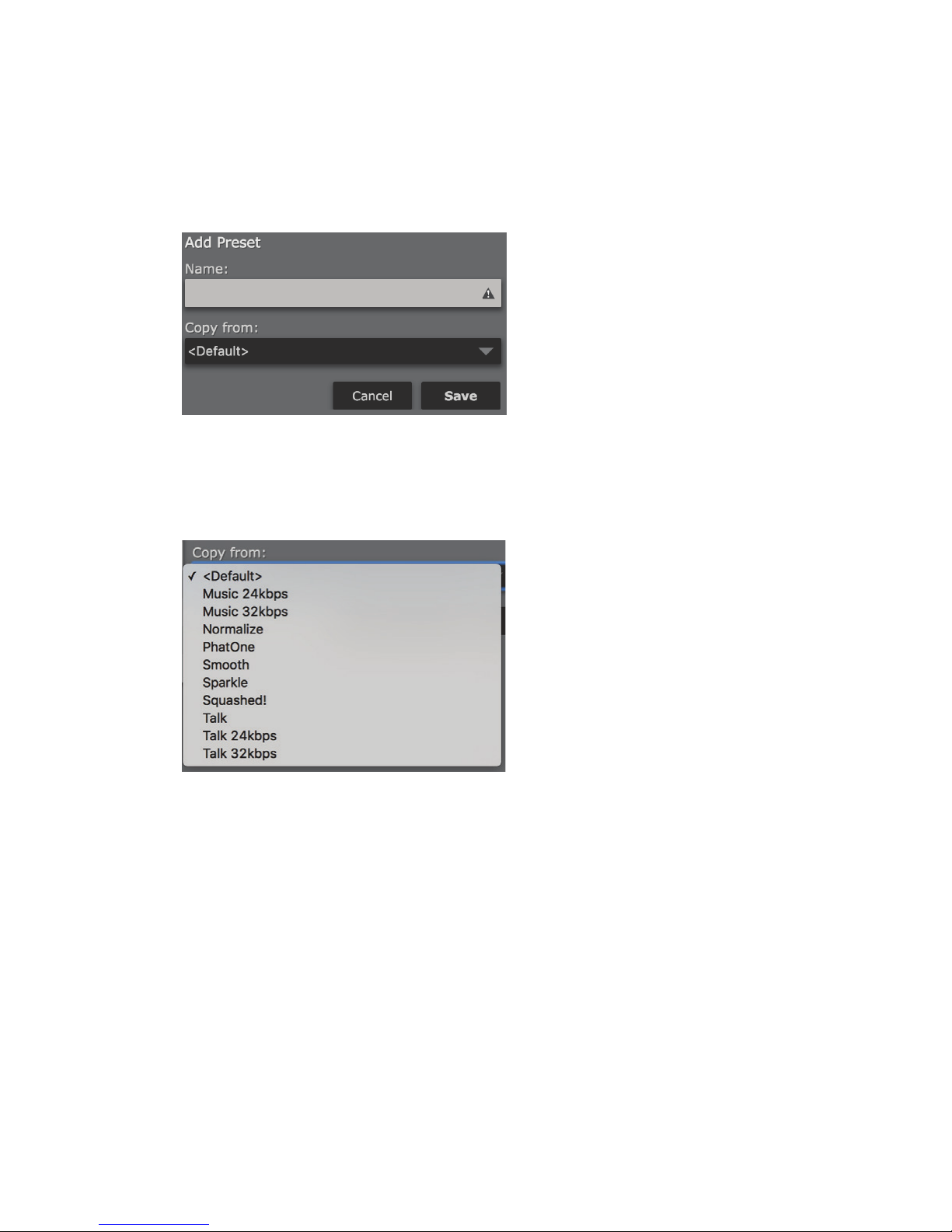
LICENSE MANAGEMENT
Add Preset
Name
Enter a “Friendly Name” for this preset (i.e. Kxxx – HOT HOT HOT) so it can be easily located in the list of
presets.
Copy from
SECTION 13
| 85
Select a factory preset as a starting point for this new preset.
Click “Cancel” to return to the presets screen without saving changes, or “Save” to create the new preset and return
to the presets screen.
Page 97
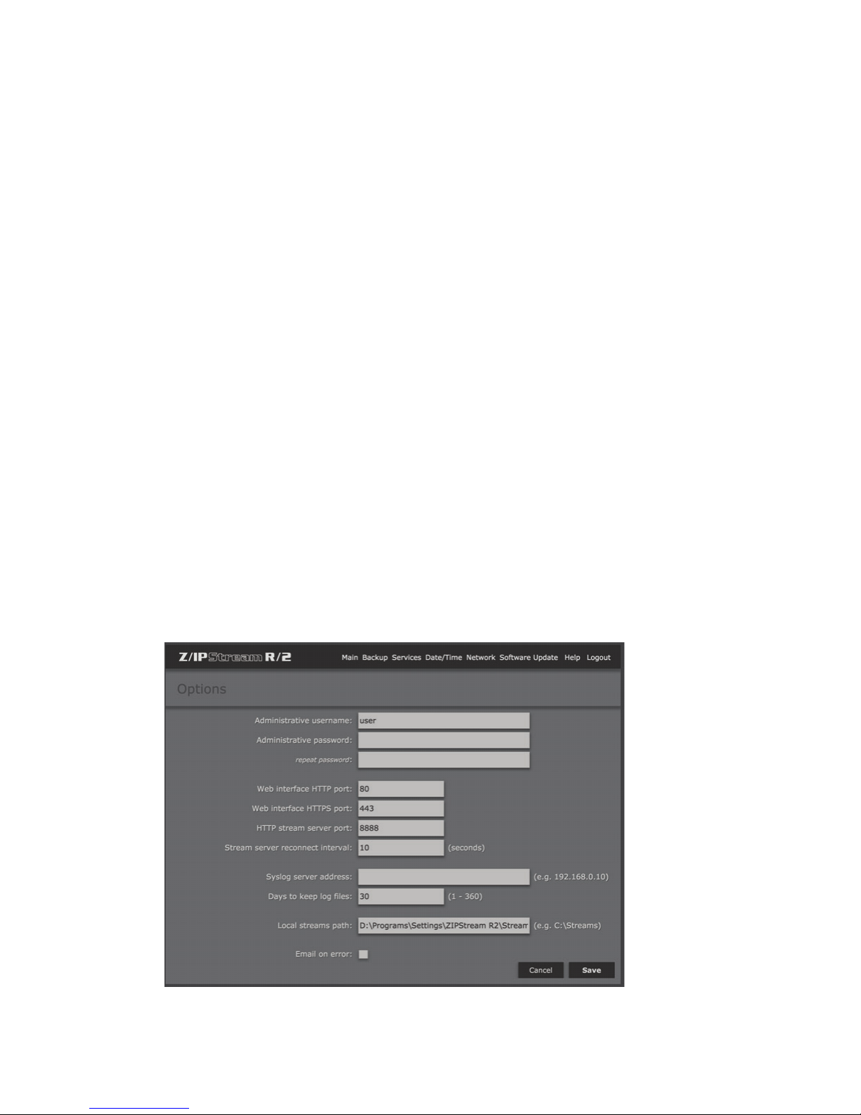
14 System Options
Overview
This chapter will cover global configuration options including:
♦ Setting administrative username and password
♦ Modifying web interface and stream server ports
♦ Configuring logging
♦ E-Mail alerts for error conditions
♦ Backup and restore of system configuration
♦ Management of services
♦ Date and Time/NTP
♦ Network interface configuration
♦ Software update
SECTION 14
| 86
Options
Page 98

SYSTEM OPTIONS
Administrative username
The default administrative login is “user”. Although only one administrative login username is supported, this
username can be changed if desired.
Administrative password
By default, this password is blank. It is highly recommended that this password be changed, particularly if the R/2 web
interface will be accessible from the public Internet. Enter the password again in the “repeat password” field.
Web interface HTTP port
Modifies the port for the internal web server for security, port conflicts, or other reasons. Port 80 is the default, as
with any other standard HTTP server.
Web interface HTTPS port
Modifies the port for the internal HTTPS (secure) web server for security, port conflicts, or other reasons. Port 443
is the default, as with any other standard HTTPS server.
HTTP stream server port
Modifies the port for the internal “test” HTTP stream server. The default is port 8888.
SECTION 14
| 87
Note:
Normally the default values for these ports are sucient. Only change them if you have a specic
reason to do so. Changes to port values will take eect after restarting R/2 or the R/2 service.
Stream server reconnect interval
Sets the interval for reconnect attempts to the stream server. The default value of 10 seconds should be sufficient in
most cases.
Syslog server address
Syslog is a protocol designed for central logging of various events occurring on equipment within a network. If you
wish to log R/2 events to a syslog server, enter the IP address for that server here.
Days to keep log les
Specify the length of time that logs should be kept on R/2, up to 360 days. The default is 30 days.
Local streams path
Specifies where HLS and other streaming files should be generated when stored locally. There is no local access
to the R/2 file system, and generally this value should not be changed from the default. See the HLS streaming
configuration examples from Chapter 8 for more details.
Page 99
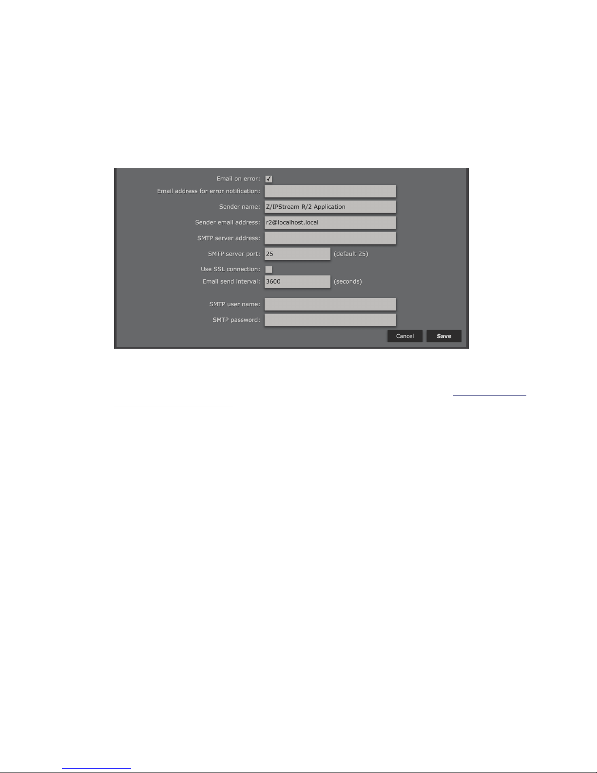
SYSTEM OPTIONS
Email on error
When this box is checked, it enables additional settings for configuring e-mail alerts in the event of an error
condition.
SECTION 14
| 88
Email address for error notication
Enter an email address in this field. While emails may be sent directly to e-mail recipients, they can also be sent as
text messages to mobile phones. If you are not familiar with how to do this, see the tutorial at http://sms411.net/
how-to-send-email-to-a-phone/.
Sender name
The default is ‘Z/IPStream R/2 application’. It will be useful to change this, if you have more than one R/2 running
in your facility).
Sender email address
Enter the account username.
SMTP server address
You may enter either an IP address in the ###.###.###.### numeric format, or a name address (e.g. smtp.gmail.
com). In order to resolve the name address, a working DNS server must be already configured on R/2 (see network
configuration details later in this chapter).
SMTP server port
The default is 25, but you may change it if necessary. Many providers are now blocking SMTP on port 25. An
alternative is port 587, which is also supported by most SMTP servers for non-secure SMTP traffic. Ideally, you will
want to point to an SMTP server on your own network (or your ISP’s network) to prevent issues with relaying.
Use SSL connection
Checking this box will ensure that your SMTP communications are encrypted and secure from hackers but it will
work only if your email service provider can accept SSL connections. A number of providers have switched from
open SMTP servers (port 25) to SSL and authentication in order to cut down on SPAM.
Page 100
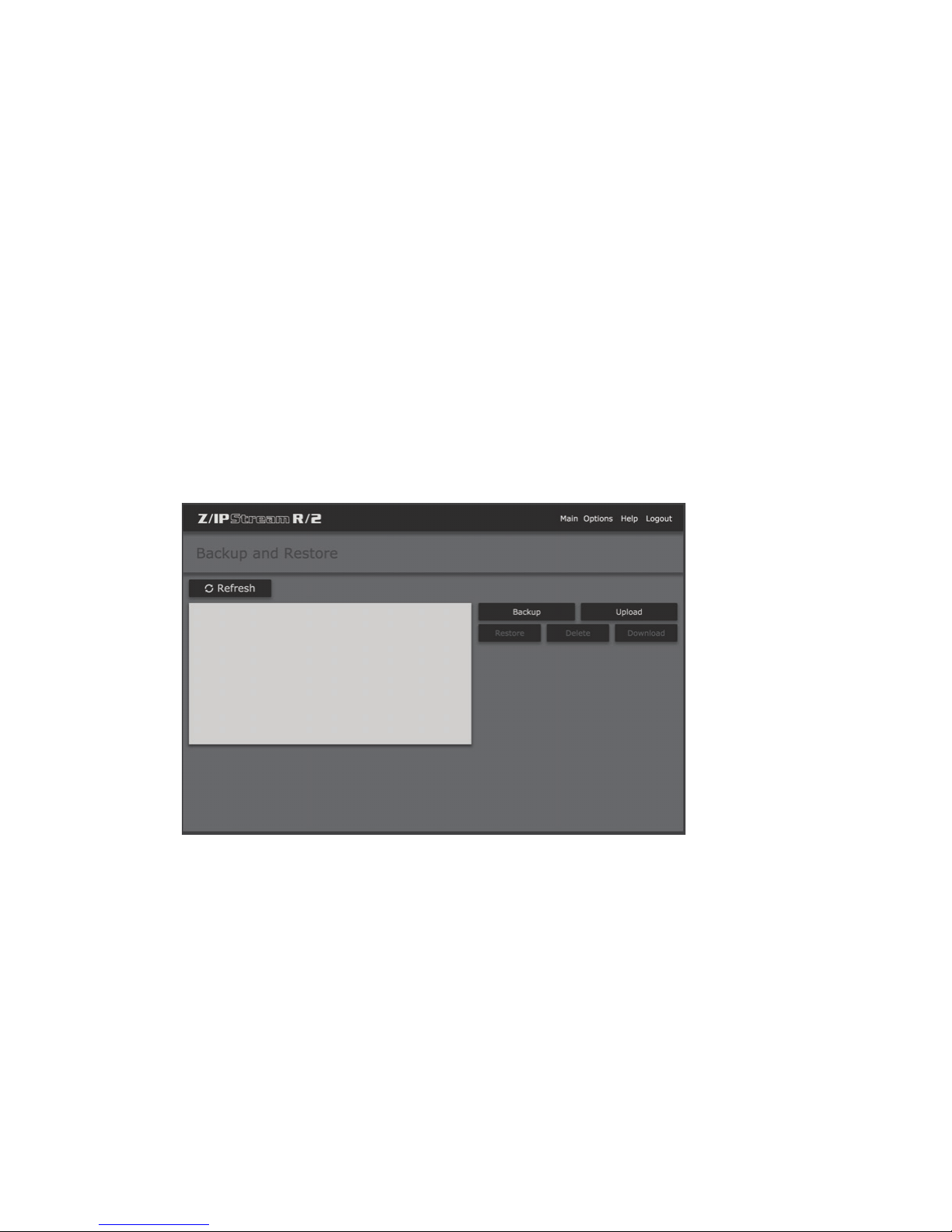
SYSTEM OPTIONS
Email send interval
Determines how frequently Z/IPStream sends you email alerts about a problem. The default is 3600 seconds (one
hour). We suggest not setting it lower. You want to have a value large enough to give you enough time to resolve the
situation before the problem repeats. Otherwise, in case of a persistent problem, you may end up having your email
flooded with too many messages.
SMTP username
Enter the user name for your SMTP server here (if applicable).
SMTP password
Enter the password for your SMTP server here (if applicable).
Click the Save button to make the changes permanent. You will then be returned to the Control Panel page.
Backup and Restore
SECTION 14
| 89
From the “Options” screen, click on “Backup” to access the Backup and Restore screen. This allows you to perform
and restore complete backups of the R/2 configuration (including presets).
Refresh
Refreshes the displayed list of backups currently on the system.
Backup
Performs a backup of the R/2 configuration.
Upload
Uploads a previously downloaded backup.
 Loading...