

Page 1
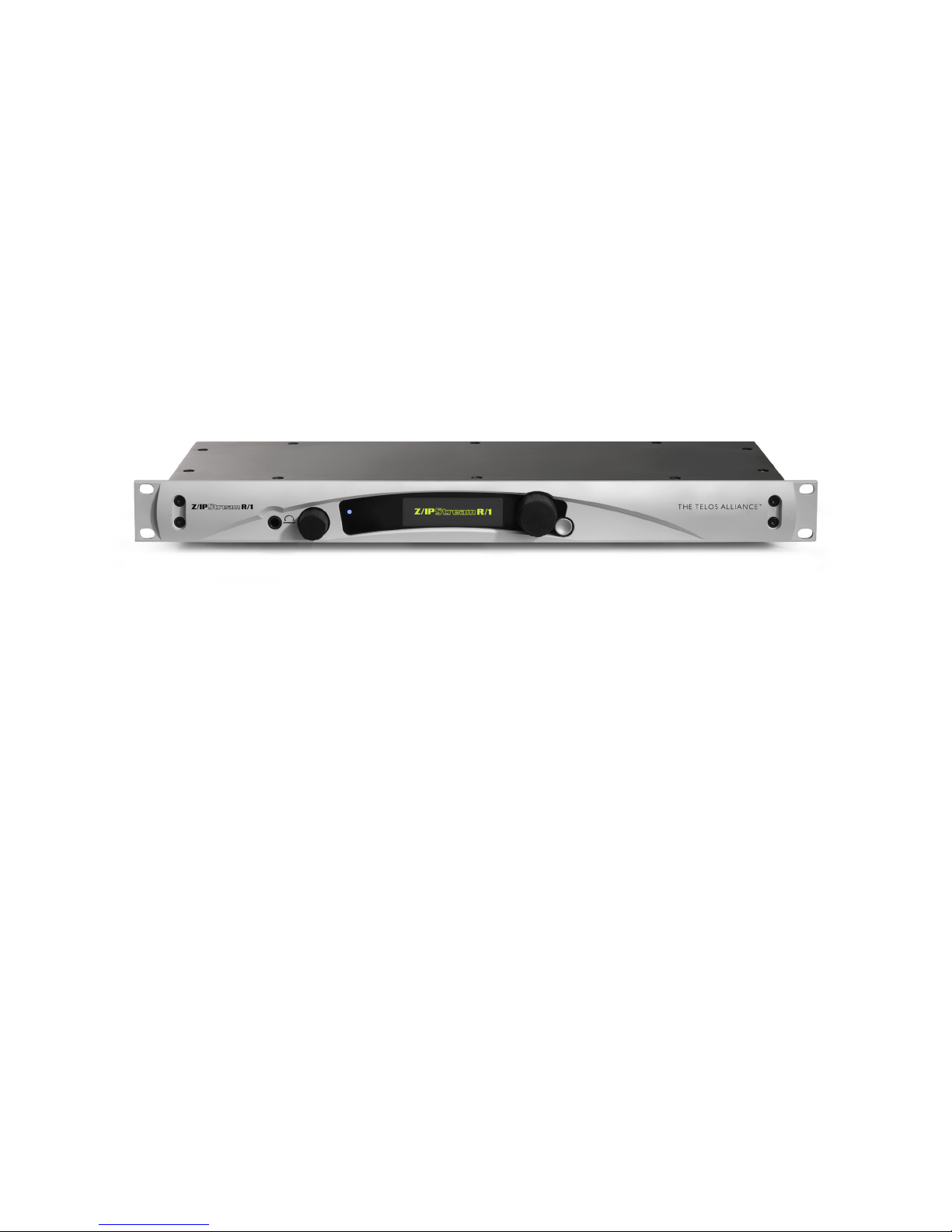
Z/IPSTREAM R/1
Encoder for Streaming Audio
USER’S MANUAL
Z/IPStream R/1 manual v3.0, for Z/IPStream R/1 software v3.0 and later
Applies to: 2001-00254
Page 2

II | Table of Contents
User Warnings and Contact Info
The installation and service instructions in this manual are for use by qualified personnel only. To avoid electric shock, do
not perform any servicing other than that contained in the operating instructions unless you are qualified to do so. Refer all
servicing to qualified personnel.
This instrument has an autoranging line voltage input. Ensure the power voltage is within the specified range of 100-240VAC.
The ~ symbol, if used, indicates an alternating current supply.
This symbol, wherever it appears, alerts you to the presence of uninsulated, dangerous voltage inside the
enclosure – voltage which may be sufficient to constitute a risk of shock.
This symbol, wherever it appears, alerts you to important operating and maintenance instructions.
Read the manual.
CAUTION: HAZARDOUS VOLTAGES
The instrument power supply incorporates an internal fuse. Hazardous voltages may still be present on some of the primary
parts even when the fuse has blown. If fuse replacement is required, replace fuse only with same type and value for continued
protection against fire.
WARNING:
The product’s power cord is the primary disconnect device. The socket outlet should be located near the device and easily
accessible. The unit should not be located such that access to the power cord is impaired. If the unit is incorporated into an
equipment rack, an easily accessible safety disconnect device should be included in the rack design.
To reduce the risk of electrical shock, do not expose this product to rain or moisture. This unit is for indoor use only.
This equipment requires the free flow of air for adequate cooling. Do not block the ventilation openings on the rear and sides
of the unit. Failure to allow proper ventilation could damage the unit or create a fire hazard. Do not place the units on a carpet,
bedding, or other materials that could interfere with any panel ventilation openings.
If the equipment is used in a manner not specified by the manufacturer, the protection provided by the equipment may be
impaired.
USA CLASS A COMPUTING DEVICE INFORMATION TO USER.
WARNING:
This equipment generates, uses, and can radiate radio-frequency energy. If it is not installed and used as directed by this
manual, it may cause interference to radio communication. This equipment complies with the limits for a Class A computing
device, as specified by FCC rules, part 15, subpart j, which are designed to provide reasonable protection against such
interference when this type of equipment is operated in a commercial environment. Operation of this equipment in a
residential area is likely to cause interference. If it does, the user will be required to eliminate the interference at the user’s
expense. Note: objectionable interference to TV or radio reception can occur if other devices are connected to this device
without the use of shielded interconnect cables. FCC rules require the use of shielded cables.
Page 3

Z/IPSTREAM R/1 | III
CANADA WARNING:
“This digital apparatus does not exceed the Class A limits for radio noise emissions set out in the radio interference regulations
of the Canadian department of communications.”
“Le présent appareil numérique n’émet pas de bruits radioélectriques dépassant les limites applicables aux appareils
numériques (de Class A) prescrites dans le règlement sur le brouillage radioélectrique édicté par le ministère des
communications du Canada.”
CE CONFORMANCE INFORMATION:
This device complies with the requirements of the EEC council directives:
♦ 93/68/EEC (CE MARKING)
♦ 73/23/EEC (SAFETY – LOW VOLTAGE DIRECTIVE)
♦ 89/336/EEC (ELECTROMAGNETIC COMPATIBILITY)
Conformity is declared to those standards: EN50081-1, EN50082-1.
Trademarks and Licenses
The Telos Alliance is a trademark of TLS Corp. All other trademarks are the property of their respective holders.
All versions, claims of compatibility, trademarks, etc. of hardware and software products not made by The Telos Alliance
which are mentioned in this manual or accompanying material are informational only. The Telos Alliance makes no
endorsement of any particular product for any purpose, nor claims any responsibility for operation or accuracy. We reserve the
right to make improvements or changes in the products described in this manual which may affect the product specifications,
or to revise the manual without notice.
This document and its content are copyrighted by TLS Corporation and may not be copied, reproduced, or distributed in any
form without expressed written permission.
Certain libraries are licensed to You under the terms of the GNU General Public License, Version 2 (“GNU GPL”). Telos is not
allowed to sub-license these libraries to You as You are deemed to have Your own direct license from the original licensee. Telos
does not modify these libraries in any way. Telos hereby offers to You, upon Your request and for the actual costs of materials
and shipping, all source code and object code files for all such GNU libraries contained in the Software. Copyright (C) 1989,
1991 Free Software Foundation, Inc., 59 Temple Place, Suite 330, Boston, MA 02111-1307 USA. Everyone is permitted to copy
and distribute verbatim copies of this license document, but changing it is not allowed.
Links to the GNU GPL and other modules used under license can be found in the About screen of the VOLT Remote Control
web interface.
Updates
Z/IPStream R/1 features and operations are determined largely by software. The Telos Alliance strives to provide the most
stable and feature-rich software available. We encourage you to check for software updates from time to time by visiting our
website or by contacting us directly.
Feedback
We welcome feedback on any aspect of our products or this manual. In the past, many good ideas from users have made their
way into software revisions or new products. Please contact us with your comments or suggestions.
Page 4

IV | Table of Contents
We support you…
By Phone/Fax
You may reach our Telos Alliance Support Team in emergencies by calling +1 (216)622-0247. For billing questions or other nonemergency technical questions, call +1 (216)241-7225 between 9:00 AM to 5:00 PM USA Eastern Time, Monday through Friday.
By Email
Non-emergency technical support is available at [email protected].
By Web
The Telos Alliance web site has a variety of information that may be useful for product selection and support.
The URL is http://www.telosalliance.com.
SERVICE
You must contact Telos Alliance before returning any equipment for factory service. We will need your unit’s serial number,
located on the back of the unit. We will issue a return authorization number, which must be written on the exterior of your
shipping container. Please do not include cables or accessories unless specifically requested by the Technical Support Engineer.
Be sure to adequately insure your shipment for its replacement value. Packages without proper authorization may be refused.
US customers, please contact Telos Alliance Technical Support at +1(216)622-0247. All other customers should contact local
representative to make arrangements for service.
WARRANTY
Telos Alliance Radio Division has an industry-leading five-year warranty.
As a company, we are commited to our products and the pursuit of providing better quality to our customers.
Find the Warranty online at www.telosalliance.com/warranty.
REGISTER YOUR PRODUCT
Take a moment to activate your coverage online at
http://telosalliance.com/product-registration/
The Telos Alliance
1241 Superior Ave. Cleveland, OH 44114 USA
+1 (216) 241-7225
For Support:
24/7 Telephone: +1(216) 622-0247
Email: [email protected]
Web: https://www.telosalliance.com/support-request
Page 5

Z/IPSTREAM R/1 | V
Table of Contents
User Warnings and Contact Info II
We Support You . . . . . . . . . . . . . . . . . . . . . . . . . . . . . IV
Register Your Product . . . . . . . . . . . . . . . . . . . . . . . . . . IV
0 A Letter from our CEO, Frank Foti VIII
1 Quickstart 1
Settings . . . . . . . . . . . . . . . . . . . . . . . . . . . . . . . . . . 1
Audio . . . . . . . . . . . . . . . . . . . . . . . . . . . . . . . . . 1
Network . . . . . . . . . . . . . . . . . . . . . . . . . . . . . . . . 2
Omnia Processing . . . . . . . . . . . . . . . . . . . . . . . . . . . . 2
Codec 1 & 2 . . . . . . . . . . . . . . . . . . . . . . . . . . . . . . . 3
MP3 . . . . . . . . . . . . . . . . . . . . . . . . . . . . . . . 3
AAC . . . . . . . . . . . . . . . . . . . . . . . . . . . . . . . . 3
Stream Conguration . . . . . . . . . . . . . . . . . . . . . . . . . . 4
SHOUTcast DNAS v2.0 Example . . . . . . . . . . . . . . . . . . . 4
ICEcast Example . . . . . . . . . . . . . . . . . . . . . . . . . . 7
2 Introducing Z/IPStream R/1 11
3 Controls and Connections 13
Overview . . . . . . . . . . . . . . . . . . . . . . . . . . . . . . . . . . 13
Front Panel. . . . . . . . . . . . . . . . . . . . . . . . . . . . . . . . . 13
Analog Audio Hardware Back Panel . . . . . . . . . . . . . . . . . . . . . . 14
Digital Audio Hardware Back Panel . . . . . . . . . . . . . . . . . . . . . . 14
Status Display . . . . . . . . . . . . . . . . . . . . . . . . . . . . . . .15
IN/OUT . . . . . . . . . . . . . . . . . . . . . . . . . . . . . . . . . 15
Automatic Gain Control (AGC). . . . . . . . . . . . . . . . . . . . . . . 16
Limit . . . . . . . . . . . . . . . . . . . . . . . . . . . . . . . . . . 16
Entering and Editing Text in the Front Panel UI . . . . . . . . . . . . . . . . . 17
text entry mode (solid cursor) . . . . . . . . . . . . . . . . . . . . . .17
erase mode (hollow rectangle cursor) . . . . . . . . . . . . . . . . . . . 17
Web Conguration . . . . . . . . . . . . . . . . . . . . . . . . . . . . .18
Default Credentials . . . . . . . . . . . . . . . . . . . . . . . . . . .18
Page 6

VI | Table of Contents
4 Z/IPStream R/1 Conguration 19
Audio Menu . . . . . . . . . . . . . . . . . . . . . . . . . . . . . . . .19
Audio I/O interface . . . . . . . . . . . . . . . . . . . . . . . . . . .19
XLR (analog). . . . . . . . . . . . . . . . . . . . . . . . . . . . 19
Livewire . . . . . . . . . . . . . . . . . . . . . . . . . . . . . . 20
AES (digital) . . . . . . . . . . . . . . . . . . . . . . . . . . . . 21
Network Menu . . . . . . . . . . . . . . . . . . . . . . . . . . . . . . . 22
LAN Interface . . . . . . . . . . . . . . . . . . . . . . . . . . . . . . 23
Mode . . . . . . . . . . . . . . . . . . . . . . . . . . . . . . . 23
IP Address. . . . . . . . . . . . . . . . . . . . . . . . . . . . . 23
Netmask . . . . . . . . . . . . . . . . . . . . . . . . . . . . .23
Gateway . . . . . . . . . . . . . . . . . . . . . . . . . . . . .23
WAN Interface . . . . . . . . . . . . . . . . . . . . . . . . . . . . .24
Mode . . . . . . . . . . . . . . . . . . . . . . . . . . . . . . . 24
IP Address. . . . . . . . . . . . . . . . . . . . . . . . . . . . . 24
Netmask . . . . . . . . . . . . . . . . . . . . . . . . . . . . .24
Gateway . . . . . . . . . . . . . . . . . . . . . . . . . . . . .24
DNS Servers. . . . . . . . . . . . . . . . . . . . . . . . . . . . . . . 24
Codec [1 & 2] . . . . . . . . . . . . . . . . . . . . . . . . . . . . . . . . 25
Compression Codec . . . . . . . . . . . . . . . . . . . . . . . . . . .26
MP3 “The standard for digital audio” . . . . . . . . . . . . . . . . . 26
AAC-LC “Low Complexity” . . . . . . . . . . . . . . . . . . . . . . 26
HE-AAC “High Eciency” . . . . . . . . . . . . . . . . . . . . . . 26
Channels . . . . . . . . . . . . . . . . . . . . . . . . . . . . . . . . 26
Bitrate . . . . . . . . . . . . . . . . . . . . . . . . . . . . . . . . . 27
Transport (AAC only) . . . . . . . . . . . . . . . . . . . . . . . . . . . 27
ADTS . . . . . . . . . . . . . . . . . . . . . . . . . . . . . . . 27
ADTS-CRC . . . . . . . . . . . . . . . . . . . . . . . . . . . . . 27
ADIF . . . . . . . . . . . . . . . . . . . . . . . . . . . . . . .27
RAW . . . . . . . . . . . . . . . . . . . . . . . . . . . . . . . 27
Page 7

Z/IPSTREAM R/1 | VII
Metadata . . . . . . . . . . . . . . . . . . . . . . . . . . . . . . . . .28
Input . . . . . . . . . . . . . . . . . . . . . . . . . . . . . . . . . . 29
Process . . . . . . . . . . . . . . . . . . . . . . . . . . . . . . . . . 30
Custom Metadata Filter Scripts . . . . . . . . . . . . . . . . . . . . . . 32
Lua Script Example . . . . . . . . . . . . . . . . . . . . . . . . . 32
Metadata Tools . . . . . . . . . . . . . . . . . . . . . . . . . .33
Streams . . . . . . . . . . . . . . . . . . . . . . . . . . . . . . . . . . 38
HTTP Streaming . . . . . . . . . . . . . . . . . . . . . . . . . . . . . 38
Streaming Services . . . . . . . . . . . . . . . . . . . . . . . . . . . 39
SHOUTcast . . . . . . . . . . . . . . . . . . . . . . . . . . . . . . .39
ICEcast . . . . . . . . . . . . . . . . . . . . . . . . . . . . . . . . . 40
RTP . . . . . . . . . . . . . . . . . . . . . . . . . . . . . . . . . .41
RTMP . . . . . . . . . . . . . . . . . . . . . . . . . . . . . . . . .42
System. . . . . . . . . . . . . . . . . . . . . . . . . . . . . . . . . . . 43
Advanced Options . . . . . . . . . . . . . . . . . . . . . . . . . . . . . . 44
Change web interface username/password . . . . . . . . . . . . . . . .44
Logs/Date Time . . . . . . . . . . . . . . . . . . . . . . . . . . . . . 45
Date/Time. . . . . . . . . . . . . . . . . . . . . . . . . . . . . 45
Logs . . . . . . . . . . . . . . . . . . . . . . . . . . . . . . .45
Ping Service . . . . . . . . . . . . . . . . . . . . . . . . . . . . . .46
Host IP . . . . . . . . . . . . . . . . . . . . . . . . . . . . . . 46
Ping Interval. . . . . . . . . . . . . . . . . . . . . . . . . . . . 46
Alarm after . . . . . . . . . . . . . . . . . . . . . . . . . . . . 46
Congure Static Routes . . . . . . . . . . . . . . . . . . . . . . . . .47
Destination Address . . . . . . . . . . . . . . . . . . . . . . . .47
Gateway Address . . . . . . . . . . . . . . . . . . . . . . . . . . 47
Interface . . . . . . . . . . . . . . . . . . . . . . . . . . . . .47
View network diagnostics . . . . . . . . . . . . . . . . . . . . . . . .48
Interface conguration . . . . . . . . . . . . . . . . . . . . . . . 48
Link information . . . . . . . . . . . . . . . . . . . . . . . . . . 48
IP rules . . . . . . . . . . . . . . . . . . . . . . . . . . . . . . 48
IP routing . . . . . . . . . . . . . . . . . . . . . . . . . . . . . 49
Page 8

VIII | Table of Contents
5 Omnia Processing 51
A1 Telos Alliance Warranty 61
A2 Specications 63
View memory usage diagnostics . . . . . . . . . . . . . . . . . . . . .50
View system diagnostics . . . . . . . . . . . . . . . . . . . . . . . . . 51
View front panel image . . . . . . . . . . . . . . . . . . . . . . . . .52
Display public IP (works only if DNS is congured) . . . . . . . . . . . . .52
Preset Editor . . . . . . . . . . . . . . . . . . . . . . . . . . . . . .52
Processor Adjustment Overview . . . . . . . . . . . . . . . . . . . 52
Processor Adjustment . . . . . . . . . . . . . . . . . . . . . . .52
Managing Presets . . . . . . . . . . . . . . . . . . . . . . . . . 59
Z/IPStream R/1 Self Test . . . . . . . . . . . . . . . . . . . . . . . . . . . 65
Page 9

War of the Waves
Dear Valued Customer,
It’s with great pride and a tip of the hat to an incredible team that I congratulate you on your new Telos
Alliance product. Everything we do here at the radio division of the Telos Alliance is with one end goal in
mind: To help broadcasters declare victory in extremely competitive environments. By purchasing this
product from us, in essence, you have declared war on your competition.
After all, the majority of Telos Alliance employees were broadcasters themselves once, and the products we’ve
developed over the years have been designed as solutions to specific issues faced on the front lines of our
industry. We’re right there in the trenches with you and have the weapons you need in your arsenal.
Telos Systems is a catalyst to out-of-this-world sound, with the most powerful and popular broadcast
telephone systems in the industry; IP/ISDN codecs and transceivers; plus processing/encoding for streaming
audio. We built an industry on the back of these amazing telephony systems, and they are still going strong.
While we at the Telos Alliance never forget our roots, we are also blazing trails in terms of new technologies
like stream-encoding and AoIP, so that all types of broadcasters can excel in this ever-evolving digital world.
Omnia Audio not only lets you stand out on the dial with your unique signature sound via legendary audio
processors, audio codecs, and microphone processing, it lets you give your listeners a better streaming
experience across devices with innovative stream encoding / processing software and hardware.
Axia Audio is a driving force behind the AES67 AoIP standard, and its networked AoIP radio consoles,
audio interfaces, networked intercom, and software products continue to move AoIP adoption forward
and help broadcasters streamline operations with cohesive, smart, and feature-rich AoIP ecosystems.
Last, but certainly not least, 25-Seven has traditionally been known for its audio delays, but its Voltair
watermark monitor/processor has made a name for itself more recently as the disruptive product that helped
broadcasters take back their ratings and harness the true power of their listening audiences.
You work so hard on your programming day-in and day-out, it deserves technology that will optimize sound
and performance at every point in the airchain and online. Armed with Telos products, you have what you
need to set your competition squarely in your crosshairs.
With that, I’ll leave you to prep your armaments. I hope that you will enjoy your Telos Alliance products for
many years to come!
Sincerely,
Frank Foti
CEO, The Telos Alliance
Page 10
QUICK START | 1
1 Quickstart
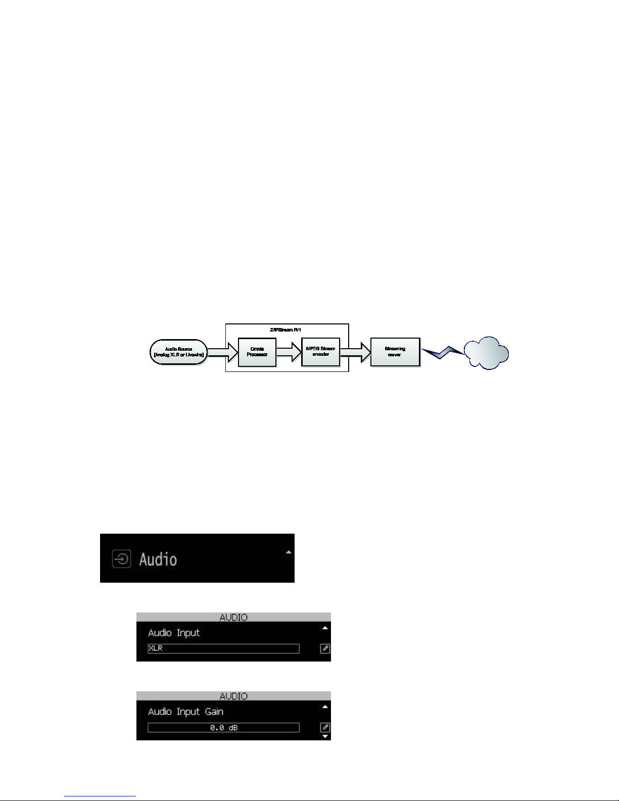
Streaming with Z/IPStream R/1 involves the following primary tasks:
1. select the audio input,
2. configure the network settings,
3. select an audio processing preset,
4. select the codec used to encode the stream, and
5. select a destination server to distribute the stream to the end-listeners.
This section walks you through a simple setup where the Z/IPStream R/1 is fed analog audio, the network settings are
configured via DHCP, and the stream is sent to a ShoutCAST v2 server. If your setup is different, you may safely skip this
section. If this is the first time you have used a Z/IPStream R/1, you may to have a look at the [Front Panel] and [Entering
Text] sections before you proceed.
Settings
From the front panel of the Z/IPStream R/1, set the following menu options.
Audio
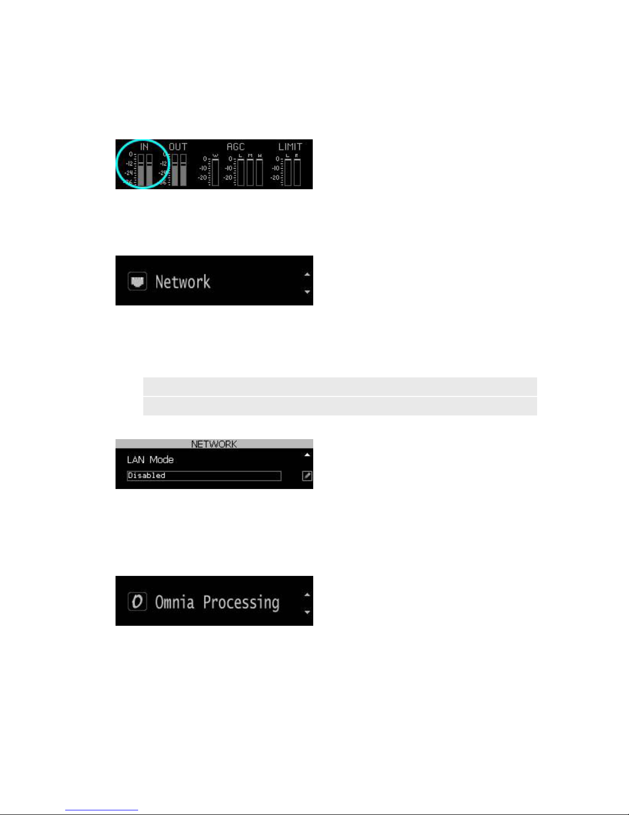
♦ Connect an audio source to the XLR inputs and select Audio Input: XLR.
♦ Verify Input Gain Setting is 0.0 db.
Page 11
2 | Section 1
Audio signal should now be visible on the input metering.
Increase INPUT gain by pressing the encoder knob, turning, and then pressing again to set the value.
Network
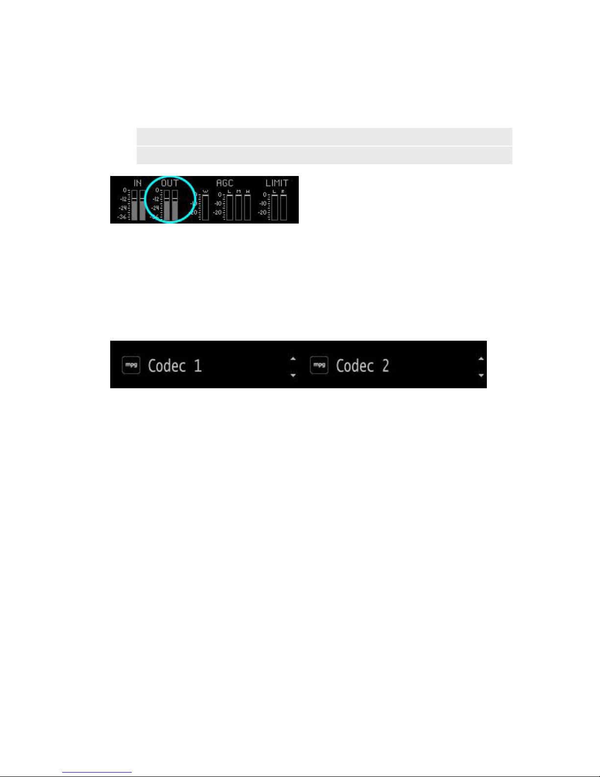
The Z/IPStream R/1 offers WAN and LAN/Livewire network ports. In most configurations you only need to
connect the WAN port to the network and the LAN port is set as “disabled”. When using Livewire, the LAN port is
connected to the Livewire network and the WAN port is connected to the public/outside network.
NOTE:
Do not connect both ports to the same network!
Unless you are using the LAN port with Livewire Audio over IP, congure it as “disabled”.
Connect the WAN Ethernet port to the network. Under Network -> WAN Mode, set the WAN port to Auto (DHCP).
After a reboot, the Network -> WAN IP Address should now show a valid IP address for the connected network.
Omnia Processing
In the Omnia Processing dialog, select a processing preset best suited to the audio source material. If unsure, use
Normalize. If no audio processing is desired, select the processing preset as [none].
Only processing preset selection is available on the front panel interface. Preset adjustment can be done via Z/
IPStream R/1’s internal web configuration by means of a web browser.
Page 12
QUICK START | 3
Note:
All Z/IPStream R/1 local outputs (XLR, Livewire, and headphone output) are post-process and
pre-encode. The post-process audio can be monitored via the output metering of the Status display.
Processing adjustments will be heard real-time on local outputs, but will be heard with a certain amount of delay
in the encoded stream. A small portion of this delay is introduced by the encoder while a much larger portion is
introduced by buffering in the server and the client used to listen to the stream.
Note: Switch headphone monitoring between pre-processed audio and post-processed audio by pressing the
headphone volume knob and selecting “Listen to [input|output] audio.”
Codec 1 & 2
Choices are MP3, AAC, or None. Common output settings are as follows:
MP3
♦ Sample Rate: 44100 Hz
♦ MP3 Channels: Stereo
♦ MP3 Bitrate (16-320 kbps): 128
AAC
Low Complexity
(Good for 3G networks)
♦ AAC Format: AAC-LC
♦ AAC Channels: Stereo
♦ AAC Bitrate(24-320 kbps): 96
♦ AAC Transport: ADTS
High Efficiency V2
(Good for Edge/2G networks and lower bit-rates)
Sample Rate: 44100 Hz
♦ AAC Format: HE-AAC v2
♦ AAC Channels: Stereo
♦ AAC Bitrate (14-56 kbps): 48
♦ AAC Transport: ADTS
Page 13

4 | Section 1
Once the Codec encoders are configured, it should be possible to monitor the encoded audio streams via a connected network audio player. Each codec can be monitored separately via the Z/IPStream R/1’s internal Stream Server.
In the table below, “ip.address” represents the IP address assigned to the Z/IPStream R/1.
Test Stream Connection URL’s
Codec 1 Codec 2
PLS: http://ip.address/play.pls PLS: http://ip.address/play2.pls
M3U: http://ip.address/play.m3u M3U: http://ip.address/play2.m3u
ASX: http://ip.address/play.asx ASX: http://ip.address/play2.asx
RAW: http://ip.address:8000 RAW: http://ip.address:8010
Note:
The Z/IPStream R/1’s playlist links are for testing only and should NEVER be deployed as public
connection points. Always use a streaming server.
Stream Conguration
Stream configurations are provided by the stream relay provider or set in the stream server configuration files. Z/
IPStream R/1 has four (4) configurable stream uplinks which can be set to push audio from either of the two (2)
available encoded codecs.
SHOUTcast DNAS v2.0 Example
The free SHOUTcast DNAS software is a good example of a streaming server. SHOUTcast DNAS is avalable at
http://www.shoutcast.com/broadcast-tools. A single SHOUTcast instance is capable of relaying both Z/IPStream
R/1 codecs, and will require the configuration of 2 of the available 4 stream configurations.
SHOUTcast configuration file
SHOUTcast operates by means of specifying a configuration file at launch, typically, sc_serv.conf. The following
parameters are needed from the SHOUTcast configuration file.
portbase=8010
password=streampwd
adminpassword=adminpwd
At least two stream ID’s should be specified.
streamid_1=1
streamid_2=2
Page 14
QUICK START | 5
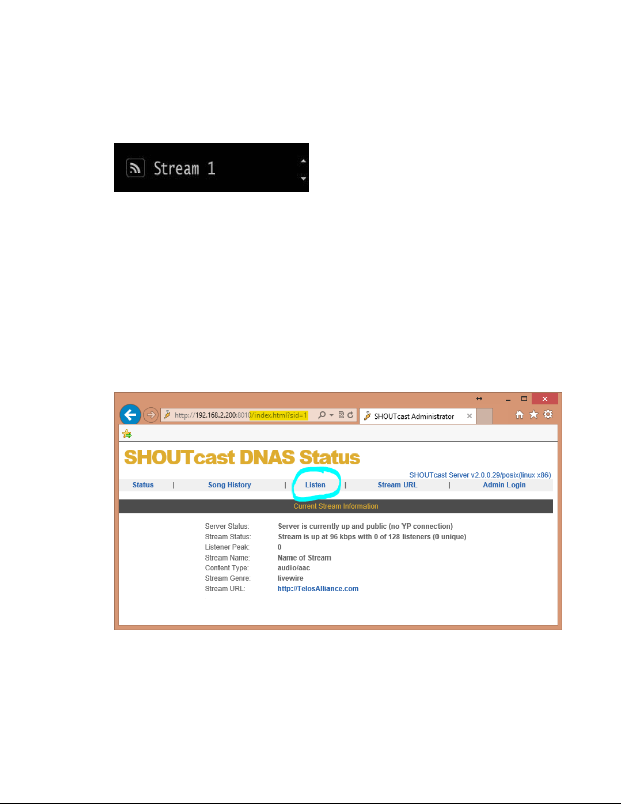
Stream 1
♦ Stream Type: SHOUTcast
♦ Codec: Codec 1
♦ Server Address: SHOUTcast.ip:{portbase} [example: 192.168.2.200:8010]
♦ Server Password: {password} [example: streampwd]
♦ Stream Name: Name of Stream [sent to clients]
♦ Stream Genre: Genre of Stream [SHOUTcast guidelines]
♦ Stream URL: URL of Station Website [sent to clients, example: http://TelosAlliance.com]
♦ Server version: version 2
♦ Stream ID: 1
♦ Stream Availability: public
The Listen link now provides a stream listen URL for client deployment.
Page 15
6 | Section 1
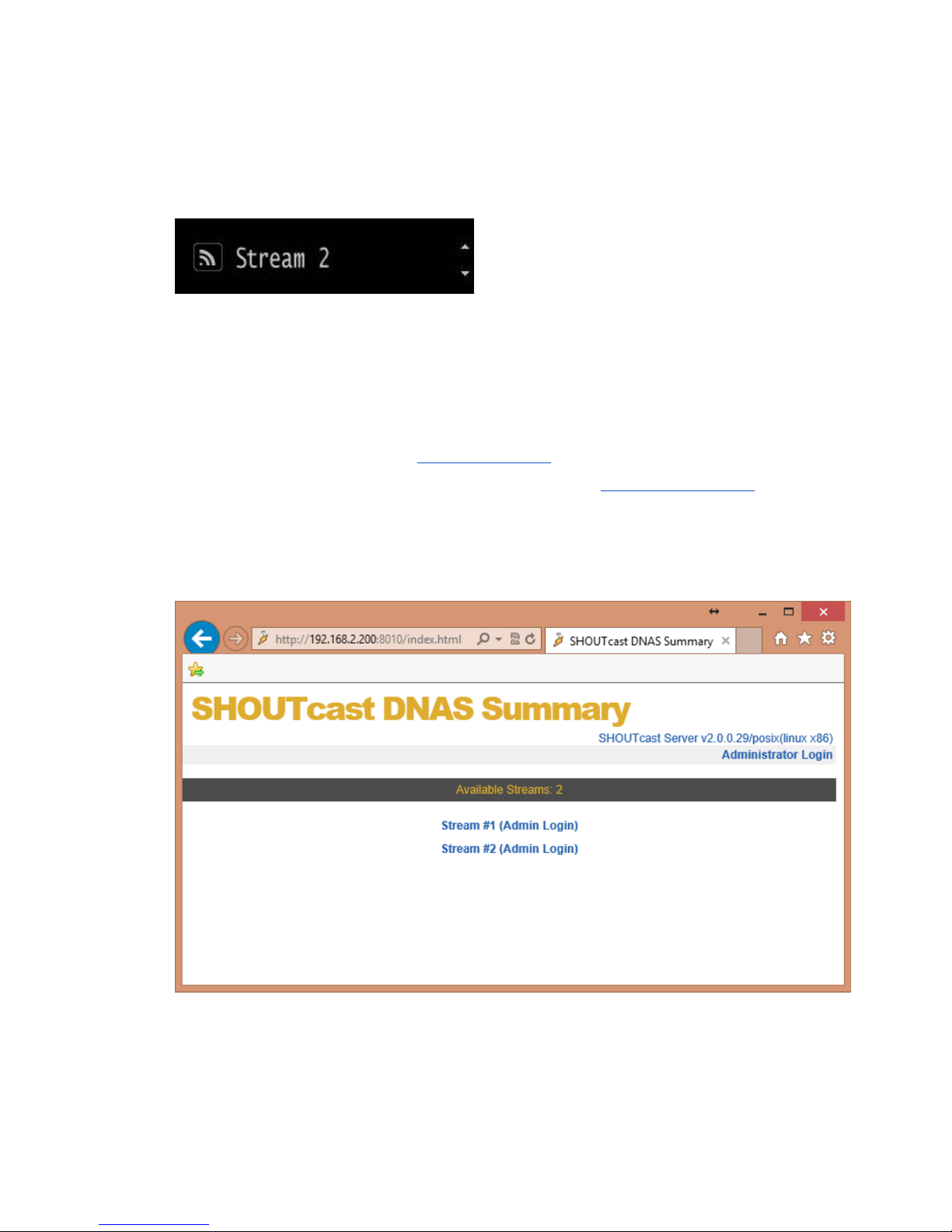
Stream 2
♦ Stream Type: SHOUTcast
♦ Codec: Codec 2
♦ Server Address: SHOUTcast.ip:{portbase} [example: 192.168.2.200:8010]
♦ Server Password: {password} [example: streampwd]
♦ Stream Name: Name of Stream [sent to clients]
♦ Stream Genre: Genre of Stream [SHOUTcast guidelines]
♦ Stream URL: URL of Station Website [sent to clients, example: http://TelosAlliance.com]
♦ Server version: version 2
♦ Stream ID: 2
♦ Stream Availability: public
Two streams are now avalable from the SHOUTcast DNAS server.
Page 16

QUICK START | 7
ICEcast Example
Icecast is a free stream relay software available from http://www.icecast.org/.
ICEcast Config file
ICEcast must be launched with a configuration file specification, typically, icecast.xml. The following parameters
are required from the ICEcast configuration file.
<authentication>
<source-password>streampwd</source-password>
<relay-password>relaypwd</relay-password>
<admin-user>admin</admin-user>
<admin-password>adminpwd</admin-password>
</authentication>
<listen-socket>
<port>8000</port>
</listen-socket>
ICEcast per-stream configuration is un-needed. Streams are distinguished by the mount point configuration which
is specified in the source device [Z/IPStream R/1].
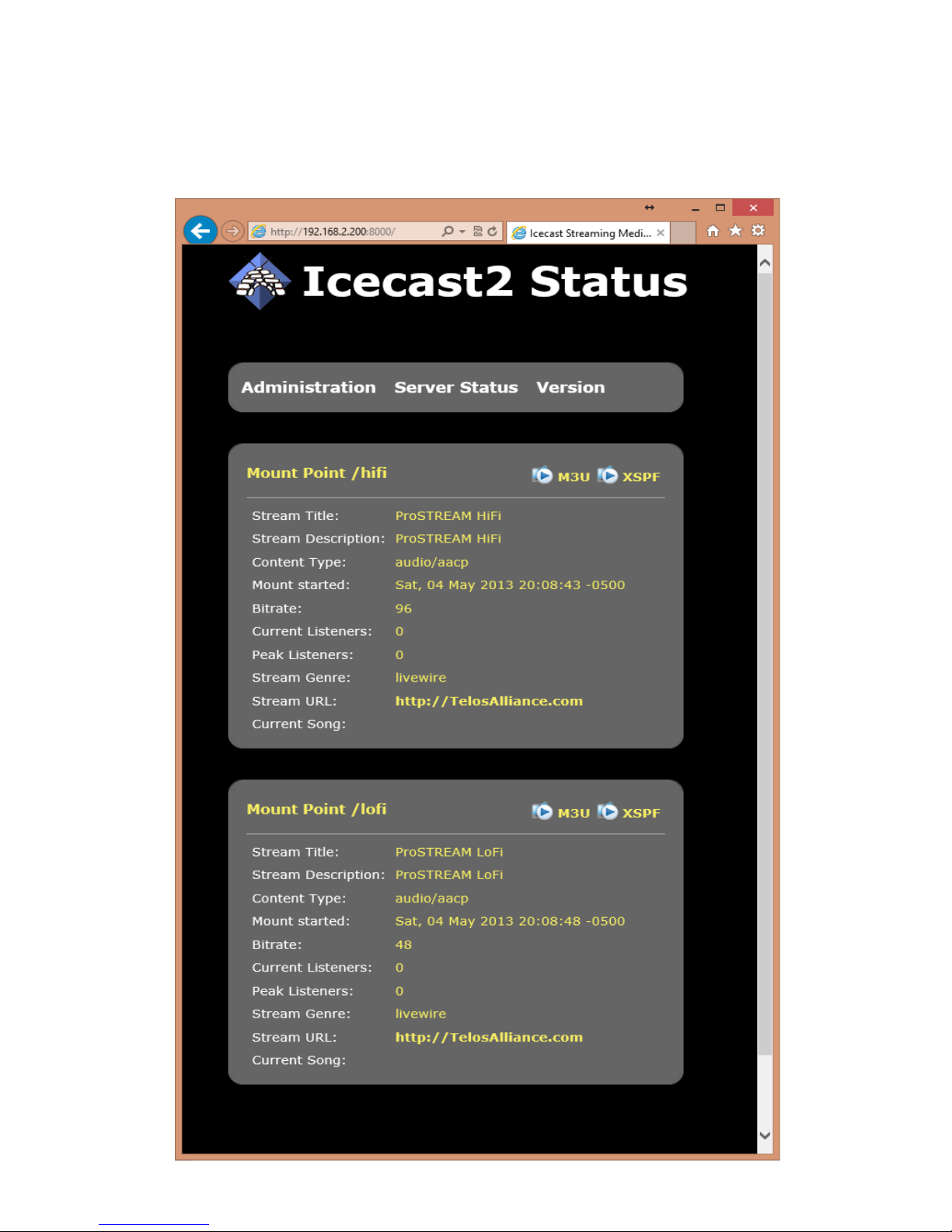
Stream 3
♦ Stream Type: ICEcast
♦ Codec: Codec 1
♦ Server Address: ICEcast.ip:{port} [example: 192.168.2.200:8000]
♦ Mount Point: hifi [can be any URL compatible string]
♦ Server Username: source [can be overridden in icecast.xml config]
♦ Server Password: <source-password> [example: streampwd]
♦ Metadata Username: <admin-user> [example: admin]
♦ Metadata Password: <admin-password> [example: adminpwd]
♦ Stream Name: Z/IPStream R/1 HiFi [sent to clients]
♦ Stream Genre: livewire
♦ Stream URL: URL of Station Website [sent to clients, example: http://TelosAlliance.com]
♦ Server version: version 2
♦ Stream Availability: public
Page 17

8 | Section 1
Stream 4
♦ Stream Type: ICEcast
♦ Codec: Codec 2
♦ Server Address: ICEcast.ip:{port} [example: 192.168.2.200:8000]
♦ Mount Point: lofi [can be any URL compatible string]
♦ Server Username: source [can be overridden in icecast.xml config]
♦ Server Password: <source-password> [example: streampwd]
♦ Metadata Username: <admin-user> [example: admin]
♦ Metadata Password: <admin-password> [example: adminpwd]
♦ Stream Name: Z/IPStream R/1 LoFi [sent to clients]
♦ Stream Genre: livewire
♦ Stream URL: URL of Station Website [sent to clients, example: http://TelosAlliance.com]
♦ Server version: version 2
♦ Stream Availability: public
Page 18
QUICK START | 9
Page 19

Page 20

INTRODUCING Z/IPSTREAM R/1 | 11
2 Introducing Z/IPStream R/1
The Telos Alliance Z/IPStream R/1 is a hardware-based audio processor and web stream encoder device in a compact 1U
rack-mount chassis. The Z/IPStream R/1 will process and encode audio sourced from either rear-mounted analog audio
inputs or via Livewire audio over IP technology1.
Z/IPStream R/1 uses Omnia Audio’s proven audio processing algorithms2 to balance the input audio according to the
program’s format. The processed audio is then encoded by two distinct encoders. Z/IPStream R/1 can send the encoded
streams to up to four streaming servers or streaming service providers. The processed audio is also sent to XLR and
Livewire outputs for monitoring.
The Z/IPStream R/1 can also accept and parse incoming metadata. The metadata is then sent along with the stream to the
streaming server, which will then distribute it to end listeners. It is important to note that listeners always connect to the
streaming server, never directly to Z/IPStream R/1.
FYI: MPEG License & Music Copyright
Musical compositions and sound recordings are creative works that are protected by the copyright laws of the United
States (title 17, U.S. Code) and other countries. Under U.S. law, the owner of a copyright has the exclusive right(and may
authorize others)to reproduce the work, use parts of the work in a new creation, distribute the work in whole or in part,
and to publicly display or perform the work (including on web pages and through webcasting). With few exceptions, it
is illegal to reproduce, distribute or broadcast a sound recording without the permission of the copyright owner. It is your
responsibility to comply with the copyright laws of the United States and other countries in which you broadcast and to
pay all applicable royalties to the copyright owners when you become a webcaster.
There have been recent amendments to the copyright law regarding webcasting of sound recordings. These new provisions allow webcasting under the terms of a statutory license, as a way to help webcasters get permission without having
to go to each sound recording’s owner. The statutory license, however, has strict requirements that you must follow. Some
of these requirements include the payment of license fees, limitations on the number of songs from the same album or
artist that may be played in a three hour period (called the sound recording performance complement); a prohibition
on publishing advance playlists; and a requirement to identify the song, artist and album on the website. There are other
requirements as well. The Recording Industry Association of America provides quite a bit of information on copyright
law as it applies to webcasting, and both ASCAP and BMI have created license agreements that they are willing to grant to
webcasters that they believe conform to the provisions of the new copyright rules for webcasting.
For additional information on the statutory license and other aspects of webcasting, please visit the following sites:
The U.S. Copyright Office http://www.copyright.gov
The Recording Industry Association of America http://www.riaa.com/issues/music/webcasting
ASCAP http://www.ascap.com/weblicense/webintro.html
BMI http://www.bmi.com/iama/webcaster/index.asp Streaming Server software
1 For more information on Livewire, please visit www.TelosAlliance.com/livewire.
2 For more information regarding Omnia processors, please visit www.TelosAlliance.com/Omnia.
Page 21

Page 22
CONTROLS AND CONNECTIONS | 13
3
Overview
The Z/IPStream R/1 is very simple to set up and use, having a minimal amount of controls and an easy, intuitive interface.
Here, we’ll take a look at the front and rear panels of your Z/IPStream R/1.
The packing box contains:
Front Panel
Controls and Connections
♦ Z/IPStream R/1 unit
♦ AC power cords (Euro 220v, US 110v, unterminated)
♦ RJ45 network cable
♦ #10 rack screws
♦ warranty registration form
♦ warranty information sheet
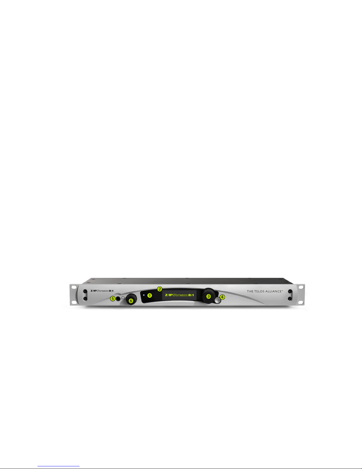
1. Power LED: The blue power LED is located to the upper left of the display. When the unit is first powered, the
power LED will flash until the unit is fully booted. When booted, the power LED will light solid.
2. Display Screen: The OLED display screen displays audio meters and configuration information. Use the display,
control knob, and return button to navigate the Z/IPStream R/1’s options and settings.
3. Control Knob: The main control knob, next to the display, works as a selector. Rotate the knob until the desired
option is displayed, then press the control knob to select the option. The control knob is also used in similar fashion
for character selection in text entry fields.
4. Back Button: The back (or escape) button is adjacent to the control knob. Pressing it steps back, or exits, from a
selected option or dialog. Pressing it repeatedly, will return you to the main screen (and will also toggle between
the main and status screens).
5. Headphone Jack: 1/4” Stereo TRS Jack for monitoring the input and post-process output audio.
6. Headphone Volume Knob: The headphone volume knob controls the output level of the audio being sent to the
headphone jack. Pressing the headphone volume knob will toggle the headphone output between monitoring the
input audio and the post-process output audio.
Page 23
14 | Section 3
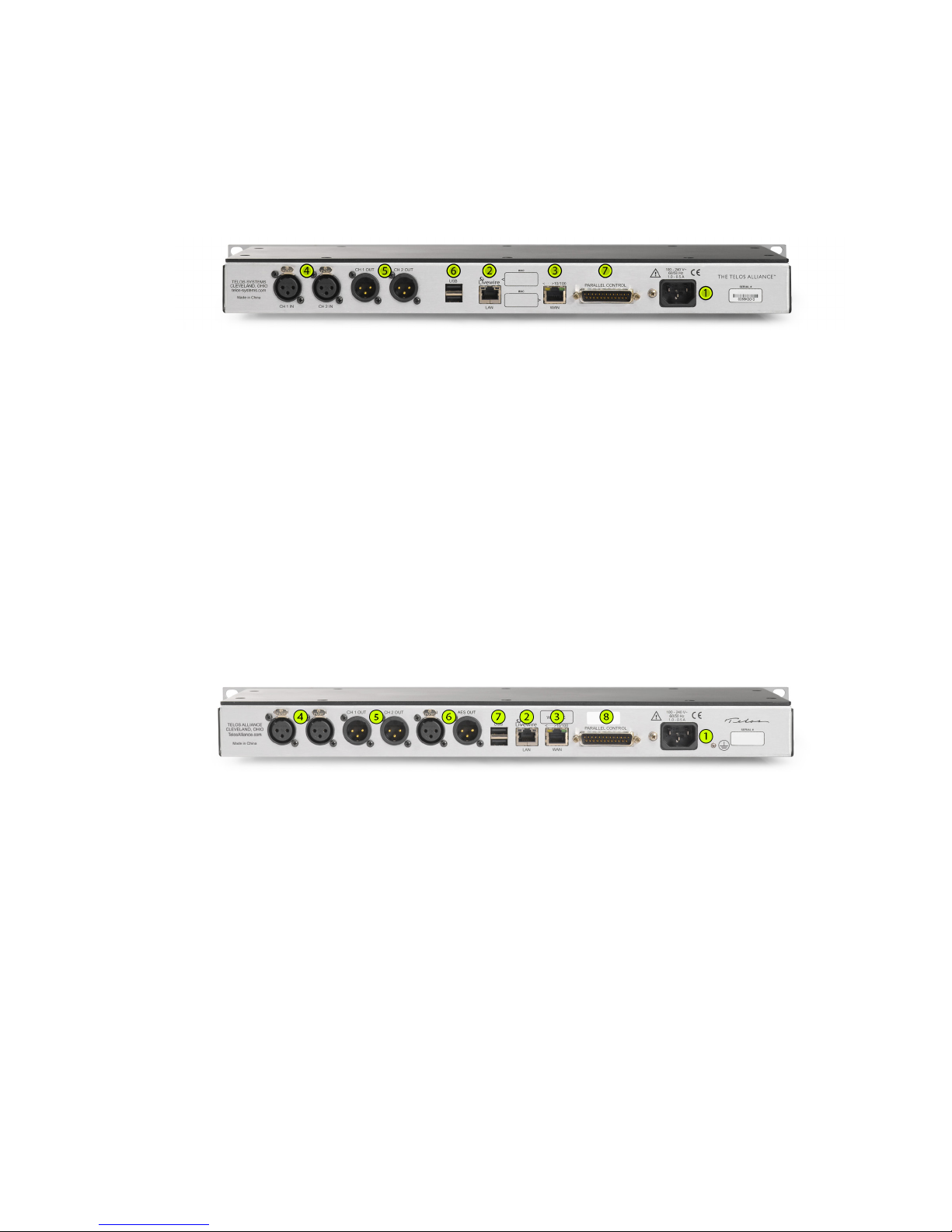
Analog Audio Hardware Back Panel
1. AC Mains connection: 110 - 220v auto-switching power connection. Use supplied power cord appropriate
for your area.
2. LAN Network: The LAN network jack is a 10/100 RJ45 jack and can be used with a Livewire network for
source audio and post-process audio monitoring.
3. WAN Network: The WAN network jack is a 10/100 RJ45 jack typically used to send the encoded streams to
streaming servers. NOTE: Z/IPStream R/1 provides two network interfaces for configuration flexibility.
If you are not using Livewire, then you only need to configure one interface. Make sure to leave the other
interface as “disabled.” Do not connect both interfaces to the same network!
4. Analog Audio Inputs: (female 3-pin XLR, left & right)
5. Analog Audio Outputs: (male 3-pin XLR, left & right)
6. USB: RS232 metadata input (with optional USB-to-Serial Adapter P/N 2091-00140)
7. Parallel Interface: no current functions
Digital Audio Hardware Back Panel
1. AC Mains connection: 110 - 220v auto-switching power connection. Use supplied power cord appropriate
for your area.
2. LAN Network: The LAN network jack is a 10/100 RJ45 jack and can be used with a Livewire network for
source audio and post-process audio monitoring.
3. WAN Network: The WAN network jack is a 10/100 RJ45 jack typically used to send the encoded streams to
streaming servers. NOTE: Z/IPStream R/1 provides two network interfaces for configuration flexibility.
If you are not using Livewire, then you only need to configure one interface. Make sure to leave the other
interface as “disabled.” Do not connect both interfaces to the same network!
4. Analog Audio Inputs: (female 3-pin XLR, left & right)
5. Analog Audio Outputs: (male 3-pin XLR, left & right)
6. Digital Audio: Input (female 3-pin XLR) / Output(male 3-pin XLR)
7. USB: RS232 metadata input (with optional USB-to-Serial Adapter P/N 2091-00140)
8. Parallel Interface: no current functions
Page 24
CONTROLS AND CONNECTIONS | 15
Status Display
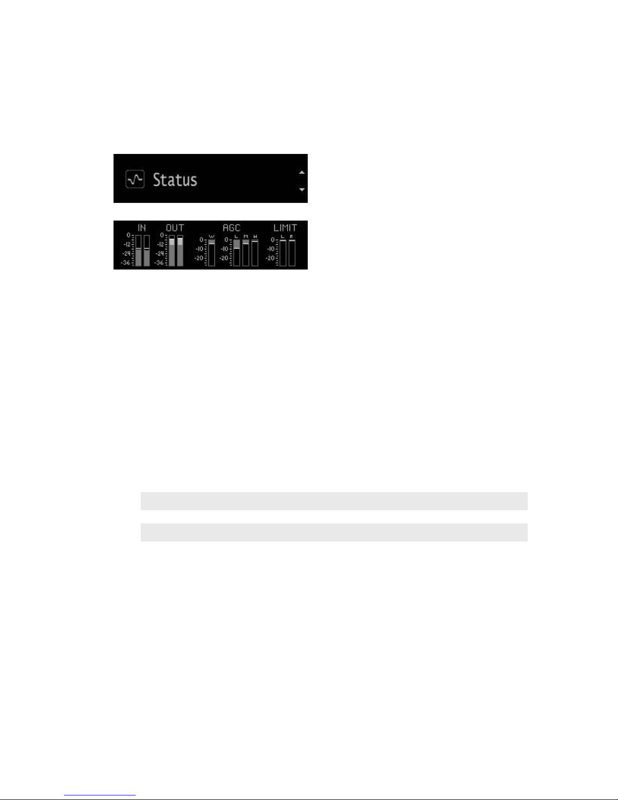
The Status screen shows the audio processing meters and indicators. Z/IPStream R/1’s audio processor is capable
of performing many different processing functions at different times, primarily based on dynamic range differences in the source audio.
The meters analyze the signals and aid in adjusting the specific parameters needed to achieve desired aural results.
Although the processing displays are capable of providing a wide range of information, we recommended setting
the audio processing based on how it sounds best to you, not relying entirely on meter indications.
IN/OUT
The Status bar graphs are capable of indicating more than just level information. The texture and density of the
audio signal can be observed, based upon the dynamic action of the bar graphs, and peak-responding pills.
Of interest are the pills at the end of the input and output meters which indicate peak level. The bar section
represents the RMS average of the signal. Wide dynamic range will display a separation between the pills and the
bar, whereas signal with little peak information will cause the pills to ride on the crest of the bar graph. The bar
graphs can indicate up to 25 dB of gain reduction.
Note:
The input and output levels are displayed relative to 0dB full scale (0dBfs). The 0 indicator on the
input/output bar graphs means that every available bit of signal level is being used at that time and
that there is nothing more in the level department, except to create distortion.
Page 25

16 | Section 3
Automatic Gain Control (AGC)
There are two sections to the AGC bar graphs display: wide-band automatic gain control (WB-AGC) and multiband automatic gain controls. The multiband AGC bands are low frequency, mid frequency, and high frequency.
The bar shows the average value of the gain reduction, while the floating pill indicates the peak value of gain
reduction.
The Omnia processor algorithms automatically adapt the style of compression/limiting control being employed
on a moment-by-moment basis. This can be deduced if the metering is studied over time. During normal operation,
the bar graphs will have a dynamic “bounce.” Every now and then, the processor will react quickly and show a
larger amount of gain reduction. This action will recover very slowly, and return to rest with the main bar graph.
This action is more apparent on dynamically textured audio.
Another feature unique to Omnia processing is processor hold. During brief pauses in audio, the bar graphs will
“freeze” indicating the processor is in the hold mode of the algorithm. This can occur when there is dry vocal audio
in the signal.
Bar graphs will indicate differently for pre-processed audio than with widely-varying audio level content. Audio
signals which lack dynamic range, whether naturally or by prior processing, will possess a lower peak to average
ratio. Conversely, audio with wide dynamic range possesses a higher peak to average ratio. Z/IPStream R/1 adapts
to each case.
Low dynamic range audio (audio with high RMS and low peak levels) will show more activity in the WB-AGC bar
graph and less activity in the multiband bar graphs. The WB-AGC responds to high RMS energy while the multiband section reacts to lower peak energy. Multiband bar graphs may not indicate any action at all with some low
dynamic range audio which is normal for Omnia processing. This may occur with heavily processed commercials
or music, or with music passages of sustained level.
Wide dynamic range audio (audio with low RMS and high peak levels) causes the opposite to occur. The multiband bar graphs become active, while the WB-AGC section appears to not respond as much. The multiband AGC’s
can work aggressively with wide dynamic range audio while the WB-AGC section indicates little activity.
The WB-AGC section is designed to operate much slower than the multiband gain controls, primarily because
of the nature of each function. The WB-AGC operates on the audio’s RMS energy. During gain calculations, the
incoming audio’s “average” level is established, and gain adjustments, if needed, are made based on those calculations. The WB-AGC bar graph will appear to move slower as it makes changes over relatively long time periods.
The intent of the multiband gain control is to normalize the spectral balance and provide control of the peak levels.
Peak energy must be detected and adjusted in a quick and accurate manner but not interfere with the sonic integrity
of the audio signal. For this reason, the multiband gain controls operate faster, with special background instructions to govern their behavior, and strictly on an as-needed basis.
Limit
The limit bar graphs monitor the level to which the processor is engaging gain reduction in the post-process audio
for each the left and right channels.
Page 26

CONTROLS AND CONNECTIONS | 17
Entering and Editing Text in the Front Panel UI
Since the Z/IPStream R/1’s user interface consists of a selector knob and back button, the method for entering
text or numeric information may not be immediately obvious. This section describes how text entry and editing is
accomplished. The task seems complex at first, especially when described in words, but it is very simple once you
have a chance to practice it a bit; similar to learning to tie one’s shoe laces.
When a text field is displayed, the pencil icon indicates that the field is changeable. Press the main knob to enter
one of the edit modes. The edit mode is indicated by the cursor shape: a solid cursor indicates text entry mode,
while a rectangle outline cursor indicates erase mode.
text entry mode (solid cursor)
In text entry mode, turning the knob cycles through all available characters. Press the main knob to select the
current character; the cursor will move to the next character position. While in text entry mode, pressing the Back
button once switches the cursor to erase mode.
erase mode (hollow rectangle cursor)
In erase mode, turning the knob erases (or restores) characters. While in erase mode, press the main knob to
return to text entry mode or press the Back button to exit field editing altogether.
Page 27
18 | Section 3
Web Conguration
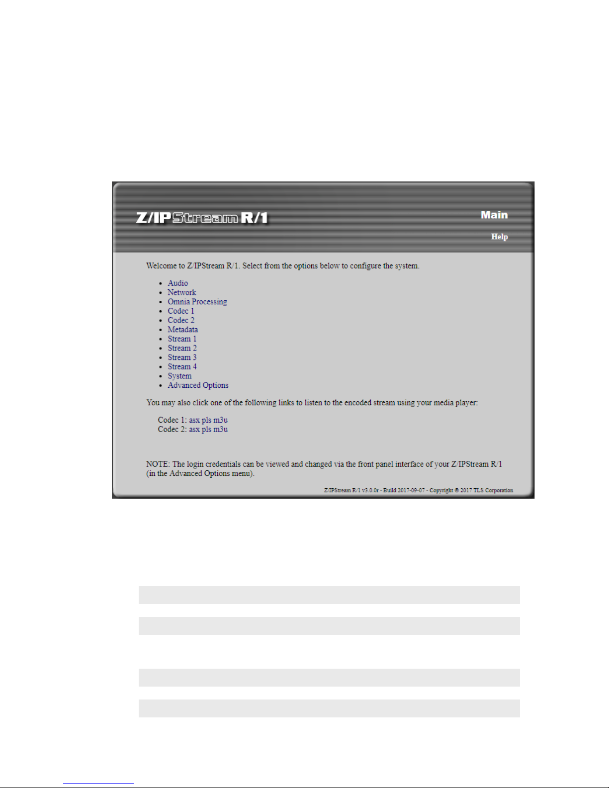
The Z/IPStream R/1 has an internal web server accessible via a web browser. The web interface can be reached by
pointing a web browser to the IP address of either LAN or WAN network, for example http://192.168.1.15/.
Default Credentials
The default username/password to access the web interface is user without password and admin/Telos.
NOTE:
For security reasons, it is very important to change the default login credentials. Failure to do so
may give others access to your Z/IPStream R/1. The login credentials can be changed on the front
panel, under the System dialog.
NOTE:
The Z/IPStream R/1 web conguration requires Javascript and HTML5 capable web browser (for
real-time Omnia processor adjustment). Some settings and values may be locked or unavailable if
they depend on other congured options.
Page 28
Z/IPSTREAM R/1 CONFIGURATION | 19
4
Audio Menu
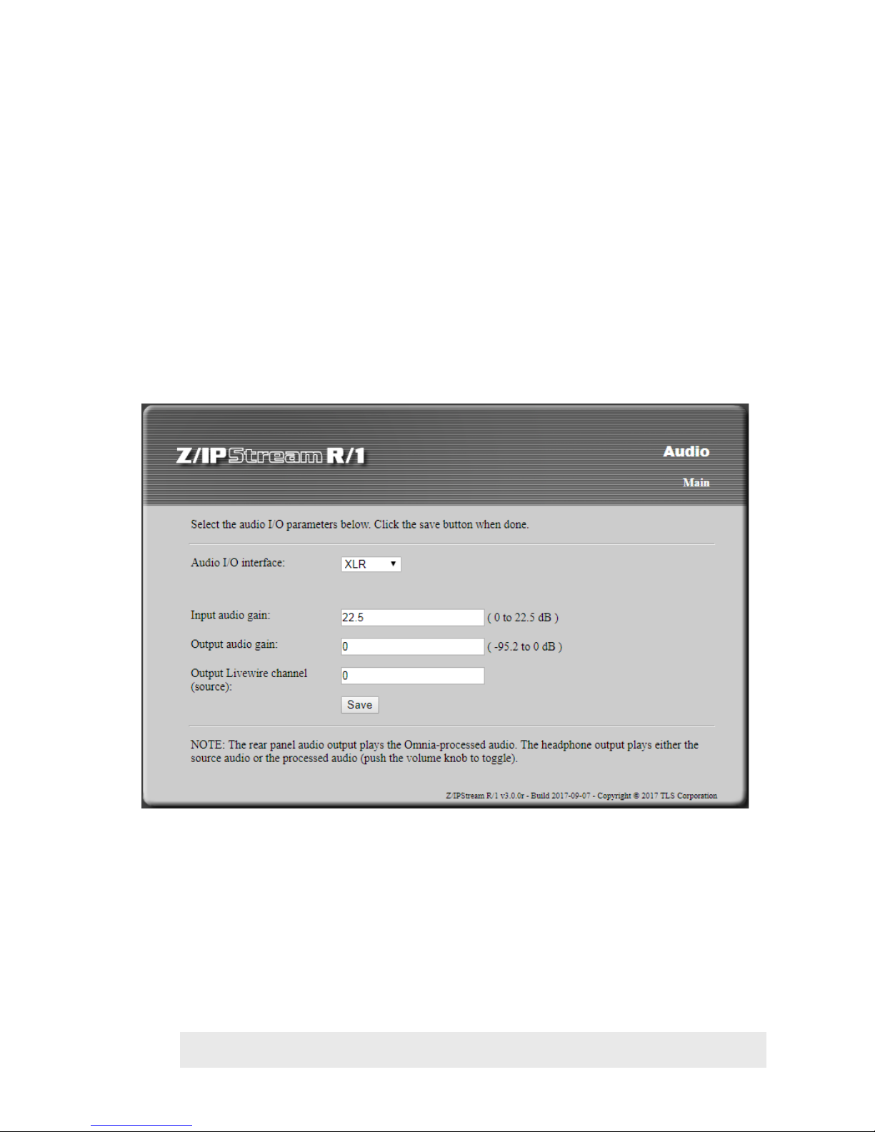
Audio I/O interface
XLR (analog)
Z/IPStream R/1 Conguration
Input audio gain
[0.0 dB - 22.5 dB] The Audio Input Level is adjustable from a 0dB level of gain to 22.5 dB level of gain. Gain level is not
necessary as +4v balanced audio will show input status at a setting of 0db.
Output audio gain
[-95.2 dB - 0.0 dB] The Audio Output Level affects the signal level for the Z/IPStream R/1’s rear outputs and Livewire
returns. The default setting of 0.0 dB will direct the full level of the processed audio to the Z/IPStream R/1 outputs.
Output Livewire channel (source):
Enter a unique channel number to appear on the Livewire audio network (connected to the Z/IPStream R/1 LAN/
Livewire network jack). Enter 0 to disable Livewire output.
Note:
The post-process audio to the encoder is unaected by the Audio output Level setting internally.
Page 29
20 | Section 4
Livewire
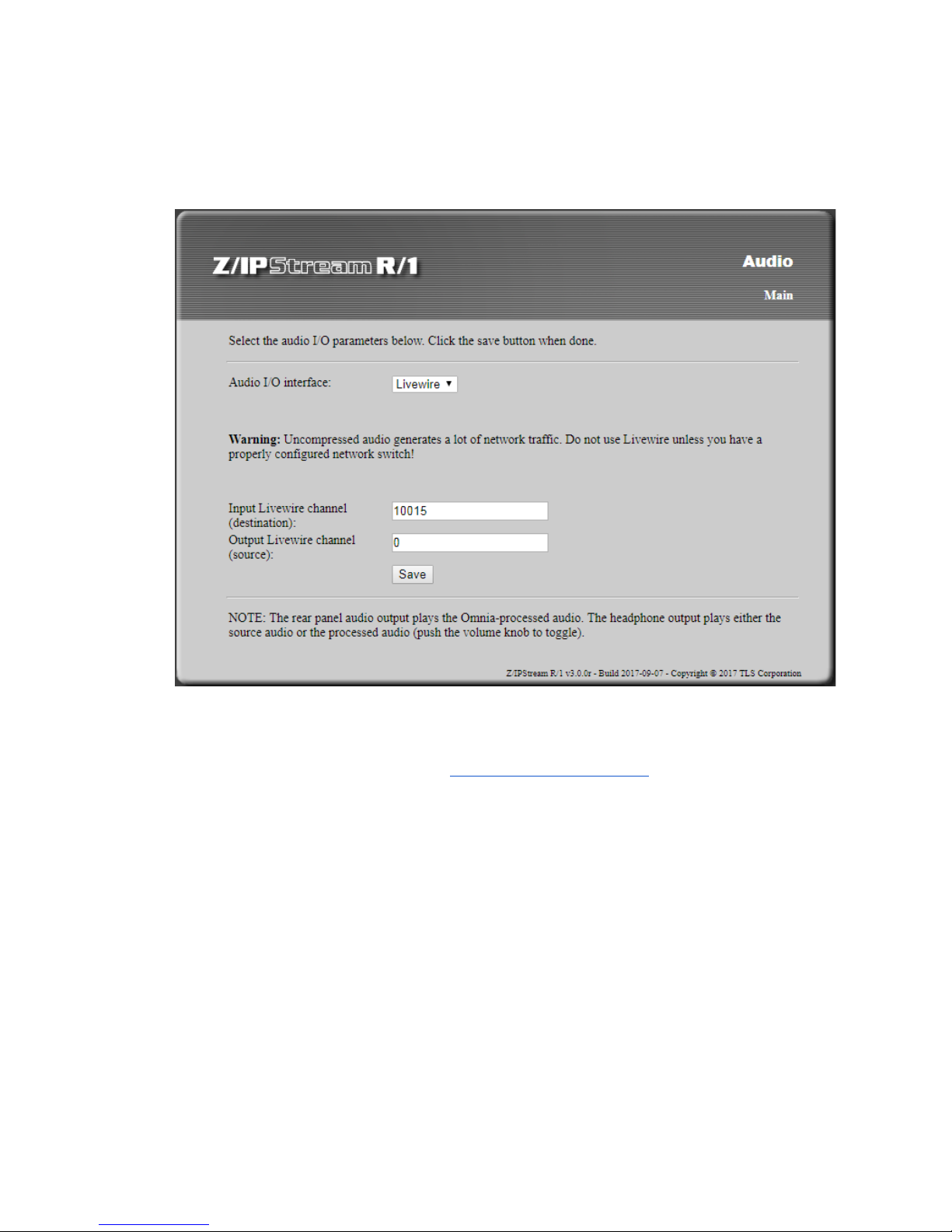
Livewire is an audio over IP technology from Axia Audio. Livewire audio requires that specific conditions be met
in the network switching environment to use Livewire functionality. As a multicast IP protocol requiring both
IGMP routing and QoS parameters, common consumer network routers and switches are unable to use Livewire IP
technology. For more information, please visit www.TelosAlliance.com/livewire.
Livewire connections should utilize the LAN port and typically imply a manual IP configuration.
Input Livewire channel (destination):
Enter the channel number of an active Livewire IP audio source channel generated by another Livewire device.
Output Livewire channel (source):
Enter a unique channel number to appear on the Livewire audio network (connected to the Z/IPStream R/1 LAN/
Livewire network jack). Enter 0 to disable Livewire output.
Page 30
Z/IPSTREAM R/1 CONFIGURATION | 21
AES (digital)
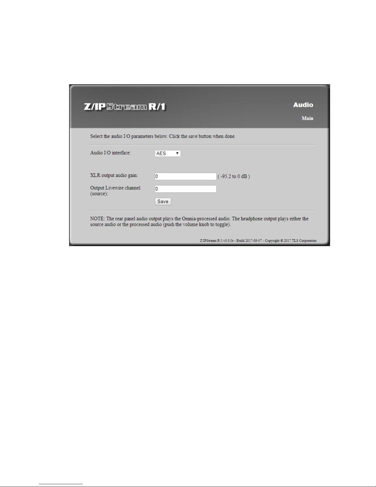
Output audio gain
[-95.2 dB - 0.0 dB] The Audio Output Level affects the signal level for the Z/IPStream R/1’s rear outputs and
Livewire returns. The default setting of 0.0 dB will direct the full level of the processed audio to the Z/IPStream R/1
outputs.
Output Livewire channel (source):
Enter a unique channel number to appear on the Livewire audio network (connected to the Z/IPStream R/1 LAN/
Livewire network jack). Enter 0 to disable Livewire output.
Page 31
22 | Section 4
Network Menu
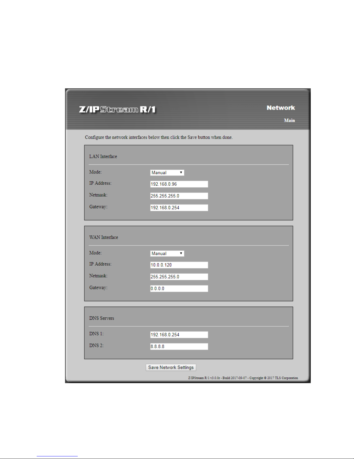
The Z/IPStream R/1 is equipped with two RJ45 gigabit network ports marked LAN [Local Area Network] and
WAN [Wide Area Network]. The networking settings of the Z/IPStream R/1 are of IPv4 conventions and must be
assigned an IP address before the Z/IPStream R/1 will communicate with any other devices.
Page 32

Z/IPSTREAM R/1 CONFIGURATION | 23
LAN Interface
Mode
(Auto) DHCP
IP address is provided by a DHCP server on the network.
Note: Livewire network devices are typically configured with a Manual IP address, not DHCP.
MANUAL
A standard IPV4 IP address must be specified.
DISABLED
Disable the LAN port.
IP Address
(Auto) DHCP
The IP Address field will show current IP address, or 0.0.0.0 if no address is assigned.
MANUAL
A valid IPV4 IP address must be specified.
Netmask
(Auto) DHCP
The Nemask field will show the value assigned by the DHCP server.
MANUAL
A valid IPV4 netmask must be specified.
Gateway
(Auto) DHCP
The Gateway field will show the value assigned by the DHCP server.
MANUAL
Specifying a gateway is optional. If the WAN port is in use for connection to the Internet, set the LAN gateway to
0.0.0.0. If the WAN port is disabled, specify the IP address of the network gateway router.
Note:
Never ll both LAN and WAN gateways. That way the network won’t be able to operate properly
unless static routes are added in Advanced Options / Congure static routes page.
Page 33

24 | Section 4
WAN Interface
Mode
(Auto) DHCP
IP address is provided by a DHCP elsewhere on the network. This is the default configuration when connecting to a
network routed by a typical consumer-brand gateway router device for Internet access.
MANUAL
A standard IPV4 IP address must be specified.
DISABLED
Disable the WAN port.
IP Address
(Auto) DHCP
The IP Address field will show current IP address, or 0.0.0.0 if no address is assigned.
MANUAL
A valid IPV4 IP address must be specified.
Netmask
(Auto) DHCP
The Nemask field will show the value assigned by the DHCP server.
MANUAL
A valid IPV4 netmask must be specified.
Gateway
(Auto) DHCP
The Gateway field will show the value assigned by the DHCP server.
MANUAL
Specifying a gateway is optional. If the WAN port is in use for connection to the Internet, specify the IP address of
the network gateway router.
Note:
Never ll both LAN and WAN gateways. That way the network won’t be able to operate properly
unless static routes are added in Advanced Options / Congure static routes page.
DNS Servers
DNS server entry is not required, but recommended. DNS is what allows a named address (google.com) to refer
to a numerical address (74.125.255.134). If local DNS servers are unknown or unavailable, Google’s public DNS
server can be used with the IP addresses 8.8.8.8 & 8.8.4.4.
Page 34
Z/IPSTREAM R/1 CONFIGURATION | 25
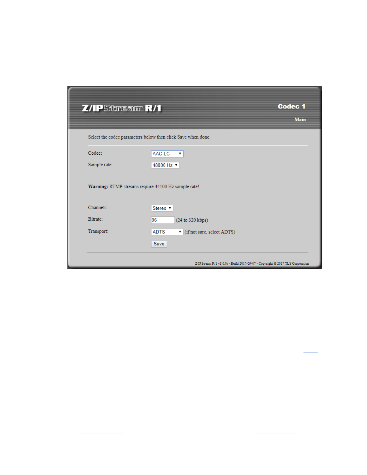
Codec [1 & 2]
The codec represents the manner in which the 1.4Mbps stream of un-compressed audio data will be converted into
a smaller data stream by means of digital compression. Z/IPStream R/1 applies lossy compression algorithms1
to the processed audio in order to create a live data stream for end users via the Internet. A lossy compression
technique produces a data stream small enough to be delivered to the client via DSL, EDGE wireless, or any
common Internet network infrastructure.
MPEG has released different standards as technology has required, and each successive standard has built upon
the previous yielding modern codecs which can deliver extremely clear audio at incomprehensibly high ratios of
compression.
1 The Telos Alliance licenses Motion Picture Experts Group [MPEG] compression codecs from Fraunhofer IIS [http://
www.iis.fraunhofer.de/en/bf/amm/produkte/audiocodec/] and includes the codecs as a source component of Z/
IPStream R/1. Lossless encoding, like a ZIP or DMG le on a computer allow an end user to un-compress the data and
restore all of the original information. In order to gain much greater compression ratios, audio compression employs
lossy compression or encoding by making certain assumptions about human hearing. For instance, a C# note played
by a guitar at 85 db of power overpowers a C harmonic of a keyboard at 30 db of power, so the 30db signal is mini-
mized or tossed.
Lossy compression relies upon subjective process, thus there are many techniques to digitally compress audio and
there are many more opinions as to which are best. In anticipation of the need for compression algorithms, the Motion
Picture Experts Group (MPEG) [http://mpeg.chiariglione.org/] was formed by the International Standards Organization
(ISO) [http://www.iso.org/] and the International Electromechanical Commission (IEC) [http://www.iec.ch/] to address
the needs of digital compression. Their research has yielded the codecs licensed and used by Z/IPStream R/1.
Page 35

26 | Section 4
When selecting a codec, there is a trade-off between more modern compression standards which sound much
better than older standards, but may risk incompatibility with older client software and devices. The core of this
choice will likely be between .MP3 (MPEG Audio Layer III) and the newer and aptly named Advanced Audio
Coding (AAC) (MPEG-4 with MPEG-2 components).
Many factors may be considered when choosing a codec to employ for the output stream.
♦ Is content mostly vocal or musical?
♦ How is the processor tuned?
♦ What types of clients are connecting to the audio stream?
Compression Codec
It is generally accepted that AAC performs better and is the codec of choice. It is rare to find clients which are MP3
only a decade after the AAC codecs became standard, but they do still exist. MP3 was released in 1993 and as the
first digital compression technique to find widespread acceptance is in most all digital stream clients that exist.
AAC benefited greatly from being the second go at audio compression as it was able to be designed with all that was
learned with MP3. AAC also boasts multiple “profiles” to fit the need of the transmission.
MP3 “The standard for digital audio”
MP3 is an all encompassing audio compression codec. MP3 is the safest choice for decoding compatibility, but
creates the least clear audio of all codecs available.
AAC-LC “Low Complexity ”
Formerly known as aacPlus or AAC+, Advanced Audio Coding’s Low Complexity codec is a high performance
codec for excellent audio quality at standard bitrates. AAC-LC can be found in widespread use, most notably
in Apple’s iTunes. When compared side by side with MP3, the superior quality of audio encoded with AAC-LC
becomes much more apparent at lower bitrates.
HE-AAC “High Ecienc y”
High Efficiency Advanced Audio Coding is a newer AAC codec and incorporates Spectral Band Replication (SBR)
bandwidth expansion to improve audio at very low bitrates.
HE-AAC v2 applies a Parametric Stereo feature to HE-AAC codec allowing for even further reduction in bandwidth.
Channels
Choose from mono or stereo encoding.
Page 36

Z/IPSTREAM R/1 CONFIGURATION | 27
Bitrate
The full spectrum of Z/IPStream R/1 encoding can be anywhere from 14-320 kbps for the output data stream
bitrate. The output bitrate constraints will differ depending on which codec is selected and whether the encode is
set to mono or stereo. The range of each codec is shown in the table below:
Codec Bitrate Range
MP3 16 to 320 kbps
AAC-LC 24 to 320 kbps
HE-AAC 24-96 kbps
HE-AAC v2 14-56 kbps
Transport (AAC only)
AAC audio encoding does not specify a container form for packaging the data stream. The Transport option allows
you to select one of four available formats: ADTS, ADTS-CRC, ADIF, or RAW. If you’re not sure about this setting,
just keep the default value (ADTS) or select a transport format that is understood by the audio player you are
targeting (some testing may be required).
ADTS
The default transport container to use for all AAC codecs is Audio Data Transport Stream (ADTS). ADTS encapsulates the packetized elementary streams of encoded AAC audio and metadata for transport over IP networks.
ADTS-CRC
ADTS-CRC includes CRC error correction and stream synchronization features to the ADTS transport and can be
used for maintaining transmission integrity when the signal is degraded.
ADIF
Audio Data Interchange Format (ADIF) is a transport container more suited to files then streaming as the data
stream is preceded with a header packet and then raw AAC data follows. ADIF may be used in applications where
the audio will be muxed with other audio channels for multi-channel transport, but is not likely to be used in
traditional streaming.
RAW
Raw mode will release the AAC data stream without any transport container at all and consists of nothing more
than the encoded audio data.
Page 37
28 | Section 4
Metadata
Metadata, or “data about the data ,” can be combined with the audio stream for delivery to end clients. The
metadata includes textual information about the current content of the audio stream, such as track title and artist,
current program titles, or branding and can also include a URL to associate with the stream.
Most end clients which are used to play the streaming audio contain displays which can be used to present the
text information in real-time. In the event that no metadata is provided to Z/IPStream R/1, the stream’s “Stream
Name” configuration will be included as the stream’s text content.
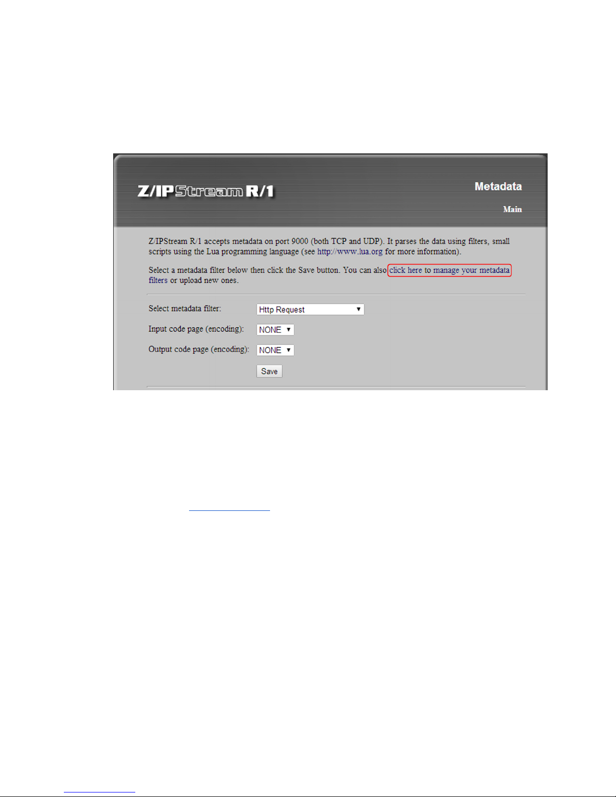
Data sent to the Z/IPStream R/1 is parsed internally by “filters”, which are short scripts using the Lua programming language (see http://www.lua.org/). Lua scripts can be modified and uploaded to Z/IPStream R/1, to
ingest incoming data and pass along the desired pieces (IE, “Track - Artist”) for real-time presentation within the
playback client. Z/IPStream R/1 ships with a set of metadata filters and you may be able to feed it with data that
matches one of the formats it understands. If your metadata source is not able to send data in one of the supported
formats, let us know and we’ll be able to help.
Page 38
Z/IPSTREAM R/1 CONFIGURATION | 29
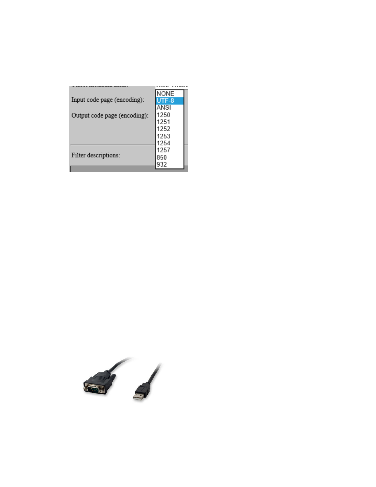
Z/IPStream R/1 is currently able to support incoming data formatted with the following code pages:
(http://en.wikipedia.org/wiki/Code_page):
♦ UTF-8 character encoding [default]
♦ ANSI - Windows
♦ 1250 – Central and East European Latin
♦ 1251 – Cyrillic
♦ 1252 – West European Latin
♦ 1253 – Greek
♦ 1254 – Turkish
♦ 1257 – Baltic
♦ 850 – “Multilingual (Latin-1)” (Western European languages)
♦ 932 - Japanese (DBCS)
Input
Automated playback systems typically provide for submitting metadata to a streaming server. Metadata connections are made to Z/IPStream R/1 via TCP, UDP connections to port 9000 or RS232 serial connections with an
RS232 to USB adapter2.
If no automated data stream is available, a manual entry form is included in Z/IPStream R/1 to allow manual entry
of playlist information.
2 Connecting RS-232 serial data requires the use of a USB to RS-232 adapter manufactured by SYBA Multimedia. Fully
tested and supported for use with the Z/IPStream R/1 (Order Telos part number 2091-00140).
Page 39
30 | Section 4
Process
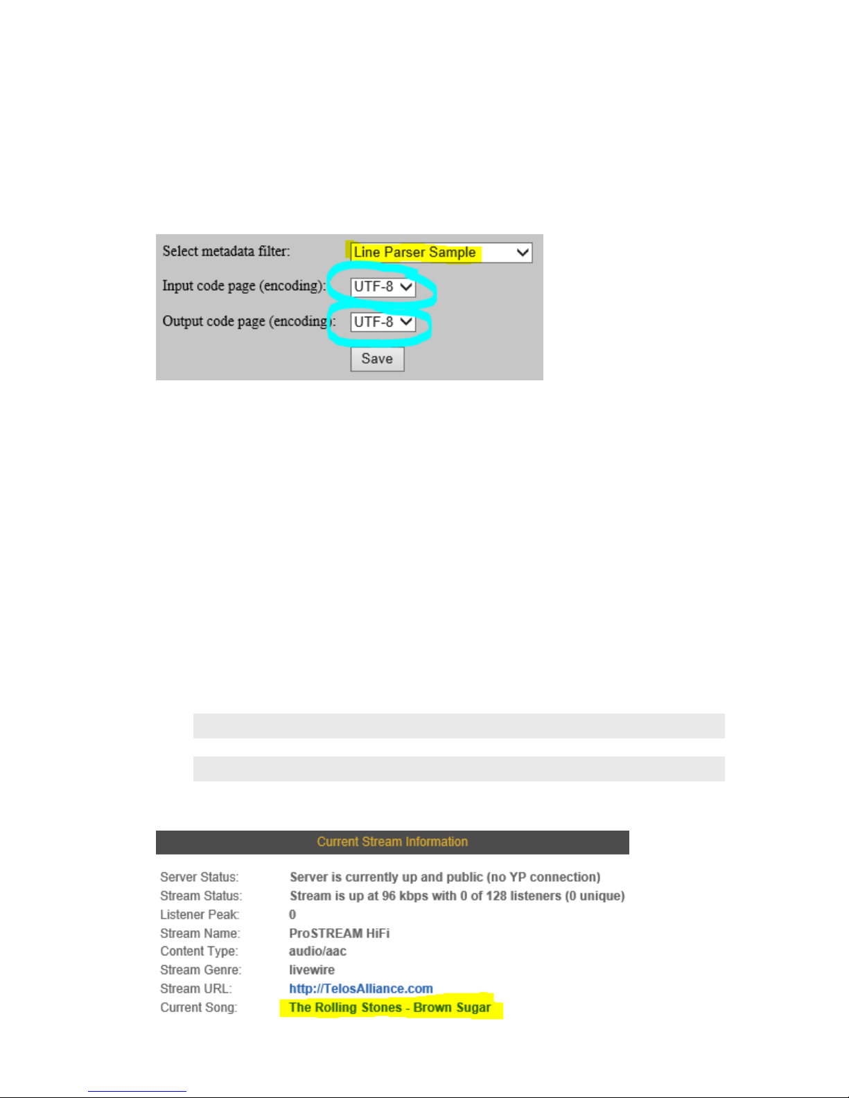
The most generic method of metadata parse is provided via the Line Parser Sample metadata filter.
As stated in the metadata table in the metadata webpage:
Line Parser Sample
This file implements a metadata filter that will parse strings that look like this: “t=title...|u=url...\n” where \n stands
for a newline character.
If the playback system has mutable output to TCP, the output string may be able to be constructed for the Z/
IPStream R/1. If so, the key parameters would resemble the following:
Playlist Data Output
♦ IP address: 192.168.2.109 [IP of Z/IPStream R/1]
♦ metadata port: 9000
♦ string output: t={title} - {artist} | u=http://mystation.org \n
The automation system would then submit that string of characters via TCP to 192.168.2.109:9000 where the Line
Parser Sample.Lua filter extrapolates the two variables from the input string and passes them to the encoder. The
Line Parser Sample filter will also log both successes and failures in the Z/IPStream R/1 system log.
Note:
The Lua Line Parser requires that TCP strings be terminated with a line feed [\n] character. This is the
indication the line lter uses to start processing the data. Character string parsers (often used with
UDP data sources) do not share this requirement.
SHOUTcast Stream Information
Page 40
Z/IPSTREAM R/1 CONFIGURATION | 31
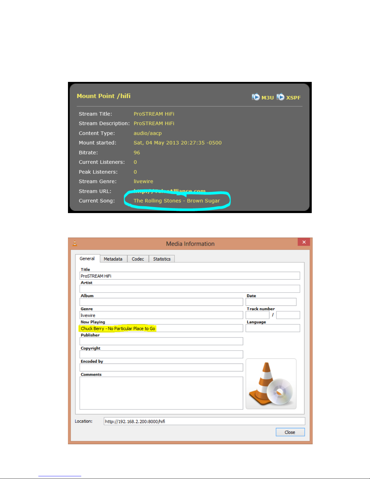
Icecast Stream Information
Connected VLC Media Player
Page 41

32 | Section 4
Custom Metadata Filter Scripts
The scripting engine inside the Z/IPStream R/1 uses the Lua Programming Language. All data arriving via port
9000 (UDP & TCP), and RS232 will pass to the Lua script. Scripts are managed via the Metadata Filters page.
Lua Script Example
The following Lua script will engage the Lua Line Parser when written to a file and saved as a Z/IPStream R/1
metadata filter.
UseLineParser()
function OnLineReceived(text,endOfLine)
local title=””
local url=”http://TelosAlliance.com”
title=text
LogInfo(“LineParser Script: title=’”,title,”’, url=’”,url,”’\n”)
SendMetaDataSong(title,url) -- Send metadata to application
end
Save this script with a name, like LineParserRaw.Lua and use the filters page of the Z/IPStream R/1 to load the file
to the Z/IPStream R/1.
This script is an example of a basic script that takes any line of text submitted, and pass it directly though the
metadata processor and reports the submitted characters to both the stream and the Z/IPStream R/1 system log
when selected as the Z/IPStream R/1’s metadata filter.
Code Breakdown
UseLineParser()
This line configures the filter to process the incoming data one line at a time. Another available option is UseXmlParser(), which will configure the filter to process the incoming data as XML. If neither of these functions are
called, the filter will default to processing the incoming data one character at a time.
function OnLineReceived(text,endOfLine)
This function is called to deal with the incoming data when the line parser is used. The line parser accumulates the
incoming data until a new line, or line feed character is detected. If the incoming line is very long, the function may
be called before an end of line character is detected. The text variable will contain the line data. The endOfLine
variable will be true if the the function was called in response to an end of line character, or false otherwise.
local title=””
local url=”http://TelosAlliance.com”
The local keyword introduces variables used by the script. The variable title is set to empty initially. The URL
is set to the home URL for the stream. You may configure a different URL string here, if required by your player.
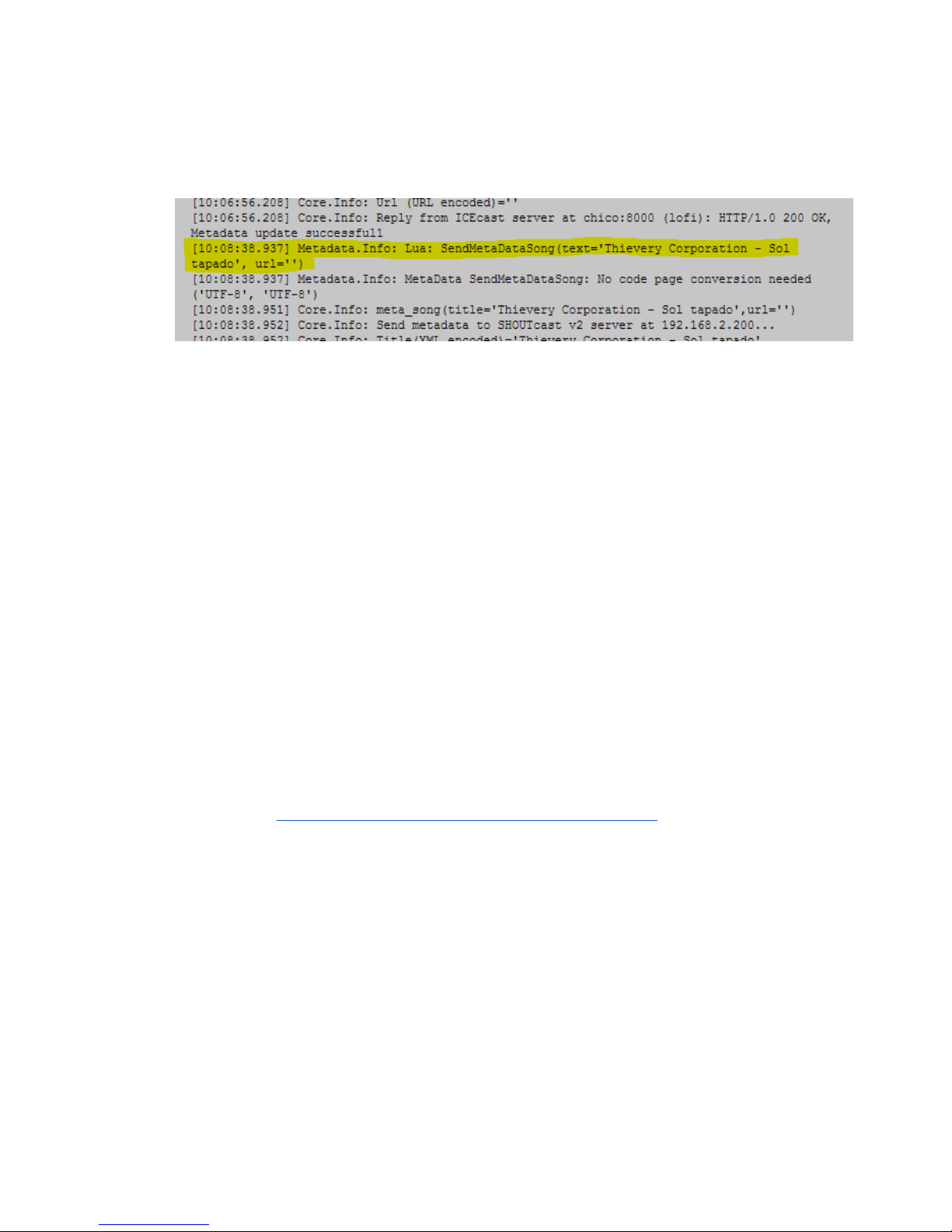
LogInfo(“LineParser Script: title=’”,title,”’, url=’”,url,”’\n”)
The LogInfo function is used to write data to the Z/IPStream R/1 logs. This function, when used in combination
with a syslog server application will allow real-time analysis of the script during the customization, or “debug”
phase of the script creation.
Page 42
Z/IPSTREAM R/1 CONFIGURATION | 33
All data inside the double quotes of the LogInfo container, (“LineParser Script: title=’”,title,”’,
url=’”,url,”’\n”) appears in the system log output. The variables from earlier in the script are specified
by name to deliver their contents to the output. The \n specifies a newline character to represent the end of our
submission to the log.
SendMetaDataSong(title,url)
The SendMetaDataSong function sends the title and url information to the stream server which will then pass it
along to the clients. Although the word “Song” appears in the function name for historical reasons, you may send
any information here; it does not have to be song related.
-- Send metadata to application
The Lua language uses two hyphens as a comment marker. The Lua interpreter will ignore any lines that begin with
two hyphens. This provides a means to “mark up”, or document, the source file with notes for future reference, but
has no effect on the function of the script. In this case, the comment is a reminder of what the role is served by this
line of code.
end
The end statement signifies the end to the commands which comprise the OnLineReceived function.
Metadata Tools
Metadata filter creation and tuning can be as nuanced as tuning an audio processor. In order to provide real-time
control of the filter process, some helpful tools are available which may assist with the process.
Metadata Pack
Download from: ftp://ftp.zephyr.com/pub/Tools/MetaData/Metadata_Pack.zip
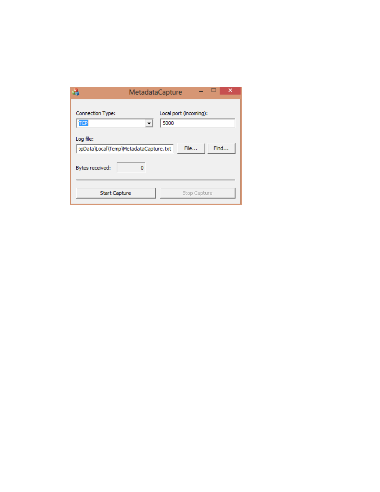
Metadata Pack contains two Windows EXE programs, MetadataCapture.exe and MetadataSend.exe.
The download also contains a PDF file explaining application use.
Page 43
34 | Section 4
MetadataCapture.exe
Metadata Capture application allows the TCP or UDP data from a remote automation system to be routed to this
application to capture a precise example of what data is being sent by the automation system to the Z/IPStream
R/1. When active, all data will be dumped to a file with timestamped delimiters.
Sample Output from Wide Orbit Automation for Radio
:::2012/10/27 23:25:08.641: Waiting for TCP connections on socket 9000:::
:::2012/10/27 23:25:14.581: Accept TCP connection on socket 9000 from
192.168.2.148:49296:::
<nowplaying><sched_time>7749700</sched_time><air_time>84336000</air_time><stack_
pos></stack_pos><title>Wah Wah Man</title><artist>Young-Holt Unlimited</
artist><trivia>What It Is! Funky Soul and Rare Gr</trivia><category>MUS</category><cart>001U</cart><intro>0</intro><end></end><station>RockLAB</station><duration>227100</duration><media_type>SONG</media_type><milliseconds_left></
milliseconds_left></nowplaying>
:::2012/10/27 23:25:23.292: Closed TCP connection on socket 9000 from
192.168.2.148:49296:::
:::2012/10/27 23:25:23.292: Exiting TCP thread on port 9000:::
Page 44
Z/IPSTREAM R/1 CONFIGURATION | 35
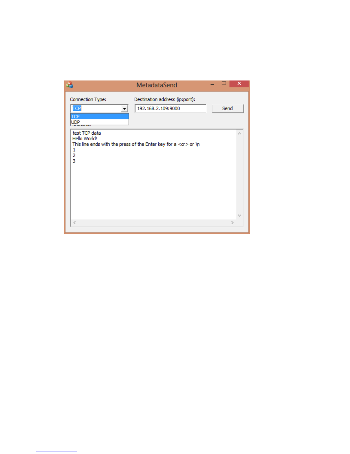
MetadataSend.exe
The Metadata Send program allows for direct push of data to the Z/IPStream R/1 on command. Copying data
from the Metadata Capture program and pasting into Metadata Send is a common way of testing the script.
Note: To emulate TCP data, a linefeed is required. Data should be entered with at least one RETURN key press at
the end of the line.
The download will also contain a PDF file explaining application use.
Page 45
36 | Section 4
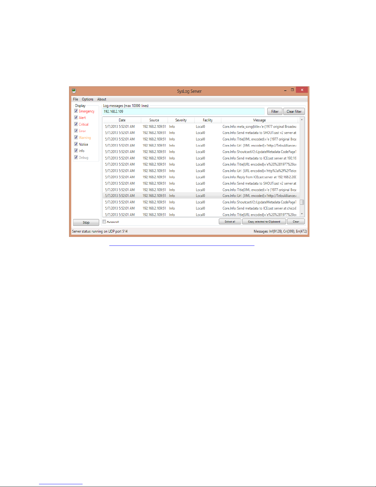
Syslog Server
Download from: ftp://ftp.zephyr.com/pub/Tools/MetaData/SyslogServer.zip
Syslog Server is a free syslog server application to display incoming system logs in real-time. If desired, logs can
also be saved to file. Seeing the log at the exact moment of submitting a test batch of data can be extremely helpful
and is recommended process for script creation.
The download will also contain a brief PDF file explaining application use.
Page 46
Z/IPSTREAM R/1 CONFIGURATION | 37
File to TCP
Download from: ftp://ftp.zephyr.com/pub/Tools/MetaData/Metadata_Pack.zip
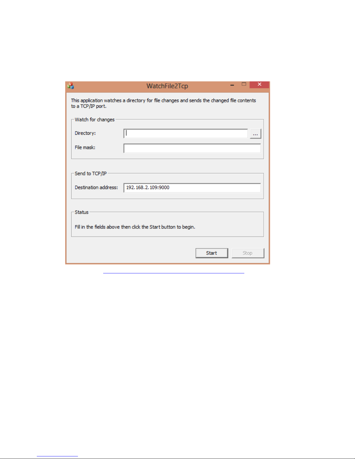
Some automation playback systems are only capable of writing metadata output to a file. The File to TCP application, when running, will watch for a file or folder to change, and when the change occurs, it copies the contents of
the file to the TCP port of the Z/IPStream R/1.
The download will also contain a PDF file explaining application use.
Command Line usage
Syntax
WatchFile2TCP.exe /run [configuration file]
Key
/run Start the instance when loaded (same as pressing the Start button manually)
Example
WatchFile2TCP.exe /run conguration_1.cfg
Page 47
38 | Section 4
Streams
Z/IPStream R/1 can be configured to push connect to up to four separate streaming servers.
Set the target server to match the required streaming server protocol.
HTTP Streaming
Z/IPStream R/1 contains a built-in mini server on TCP port 8000. This server can accept only a few connections
and should not be used as the main streaming server or be deployed to the public.
The HTTP server is intended to be used for stream monitoring with a player or to have another media server pull
the stream from Z/IPStream R/1 allowing monitoring of the encoded stream. This is helpful in troubleshooting
server connections or just as a quick way to test everything is working as expected. The HTTP server is also useful
when adjusting audio processing parameters as the audio can be monitored with compression. The audio delay
should also be shorter than listening to the stream delivered through an external server.
Page 48

Z/IPSTREAM R/1 CONFIGURATION | 39
Test Stream Connection URL’s
Codec 1 Codec 2
PLS: http://ip.address/play.pls PLS: http://ip.address/play2.pls
M3U: http://ip.address/play.m3u M3U: http://ip.address/play2.m3u
ASX: http://ip.address/play.asx ASX: http://ip.address/play2.asx
RAW: http://ip.address:8000 RAW: http://ip.address:8010
Streaming Services
A streaming service can provide all that is needed for distribution of Z/IPStream R/1’s encoded audio stream.
Typically pricing via a monthly base rate and bandwidth costs. The streaming service provider will provide the
stream configurations for Z/IPStream R/1 and return to the client any number of services including stream link
URL’s to provide to listeners. A streaming service can also provide failover and optional configurations should a
connection be lost.
Stream Server Service Providers
♦ TritonDigital: http://www.tritondigital.com/
♦ Akamai: http://www.akamai.com/
♦ LimeLight: http://www.limelight.com/
♦ Stream Guys: http://www.streamguys.com/
Additional streaming services can be found at http://www.radiotoolbox.com/hosts/
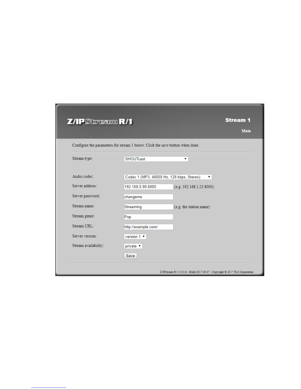
SHOUTcast
Target Server
Set the target server to SHOUTcast.
SHOUTcast Server Address
IP.address:port of the SHOUTcast server, I.E. 192.168.2.200:8010
SHOUTcast Server Password
Value of password= from the SHOUTcast configuration file.
Stream Name
When an Internet user or device connects to the stream, the Stream Name will be sent in the initial meta data burst.
This title is typically displayed on the end-user’s player or device. Capitalization and punctuation of Stream Name
is fine and will be displayed as such in the end client.
Stream Genre
SHOUTcast DNAS server requires a genre field for all incoming connections. While the genre may not be displayed
on the end user’s device or client application, some streaming servers and services may publish the existence of the
encoded audio stream in a directory. SHOUTcast recommends the genres listed in their forums: http://forums.
winamp.com/showthread.php?t=303241
Stream URL
When an Internet user or device connects to the stream, the Stream URL will be sent in the initial meta data burst.
This value can be set to an URL that is common to all the songs streamed to the SHOUTcast server (e.g. the website
of the radio station).
Page 49

40 | Section 4
Server version
Z/IPStream R/1 can connect to SHOUTcast servers using SHOUTcast protocol version 1 or a newer enhanced
SHOUTcast protocol version 2. If the server version is not known it will probably be the older protocol version 1.
Stream ID
If the SHOUTcast protocol version 2 is selected, a stream ID must be entered. Typically this will be 1 if only one
stream is sent to the server.
Stream availability
Allows defining if the stream is meant to be public and can be included in a server specific directory listings or
private and should not be listed to the end-users. A good example of this is SHOUTcast DNAS which will publish
any streams configured as public to http://www.SHOUTcast.com/.
ICEcast
Target Server
Set the target server to ICEcast.
Audio Codec
Select which of the encoded streams will be delivered by this configuration.
ICEcast Server Address
IP.address:port of the ICEcast server, I.E. 192.168.2.200:8010
Mount Point
Specify a unique URL compatible string for the connection URL for the stream, I.E. hifi to have the connect string
for this stream be http://192.168.2.200:8000/hifi. It is acceptable to specify an extension if desired, such as .mp3
or .aac.
Stream User Name
The default stream username for ICEcast is source unless it is overridden in the icecast.xml configuration file.
Stream Password
The stream password from the icecast.xml configuration file.
Metadata User Name
The ICEcast administrator username. Note that the configuration will work without a metadata username, but
metadata will not pass to ICEcast or clients.
Metadata Password
The administrator password from the icecast.xml configuration file. Note that the configuration will work without
a metadata username, but metadata will not pass to ICEcast.
Stream Name
The name of the stream as displayed to clients.
Stream Genre
Genre of the audio stream.
Stream URL
Web address of the station’s website.
Stream availability
Allows defining if the stream is meant to be public and can be included in a server specific directory listings or
private and should not be listed to the end-users.
Page 50
Z/IPSTREAM R/1 CONFIGURATION | 41
RTP
Target Server
Set the target server to RTP
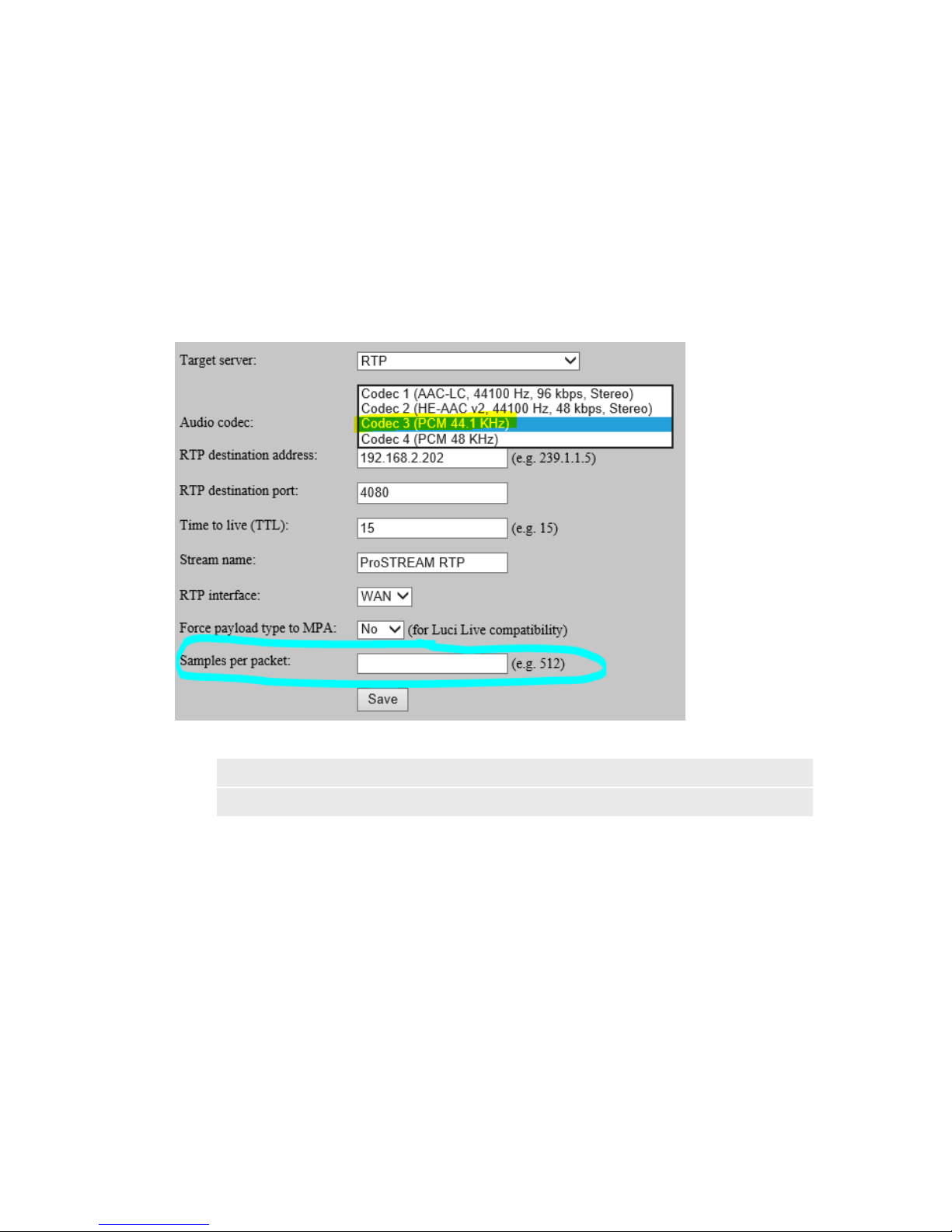
Audio Codec
Specify which of the two codec encodes to use for the RTP stream.
Note:
RTP allows uncompressed delivery as well. Select a PCM codec to be able to specify the Samples
per RTP packet.
RTP destination address
Enter the destination UDP address to which RTP packets will be sent. Address can be unicast or multicast.
RTP destination port
Enter the UDP port to which RTP packets will be sent.
Time to live (TTL)
Defines how “far” from a sending host a given UDP packet should be forwarded. For example, use value 1 to limit
UDP streams to local network subnet only.
Stream name
The name entered here will be sent in the SDP discovery broadcast messages. This title is typically displayed on the
end-user’s player or device when stream is discovered and played.
RTP interface
If more than one network interface for Z/IPStream R/1 is configured, RTP interface selection allows to define to
which network interface RTP stream will be sent. Usually interface needs to be set to LAN to broadcast stream to
Local Area Network.
Page 51
42 | Section 4
RTMP
Target server
Set the target server to RTMP for RTMP streaming services. Service providers like TritonDigital, Akamai, and
LimeLight often use RTMP services for live audio streaming.
Server address
Enter the server address and port number where the address and port are separated by a colon character. For
example, if the address is 192.168.1.23 and the port is 1935, you would enter 192.168.1.23:1935 in the address
field.
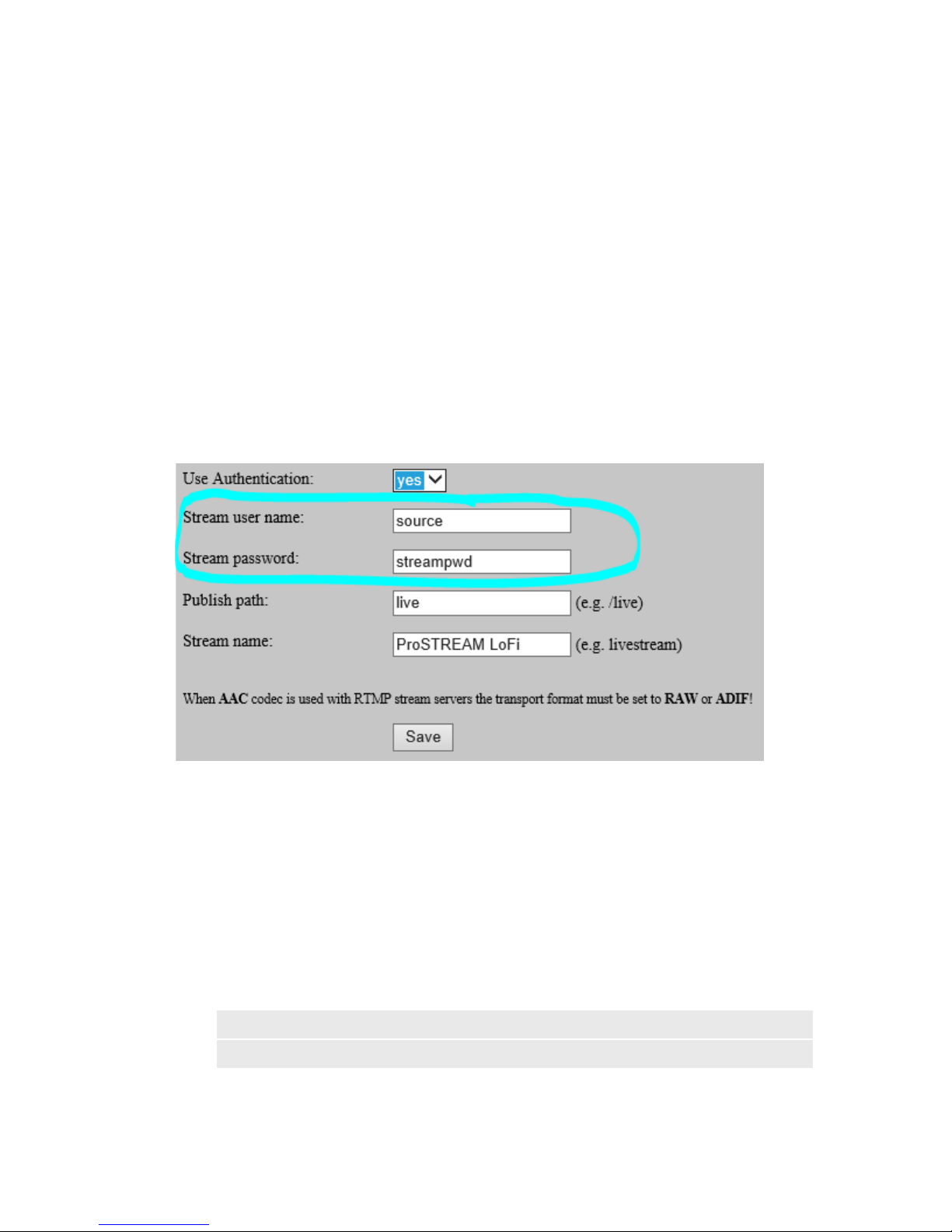
Use Authentication
If RTMP server needs authentication, set this field to “yes.” The fields for stream username and stream password
will appear automatically.
Stream user name
If RTMP authentication is selected, enter the server username.
Stream password
If RTMP authentication is selected, enter the server password.
Publish path
Enter the stream publish path. Usually this will be the RTMP application name used to receive the stream(e.g.
“live” is the default RTMP application for Adobe Flash Media Server).
Stream name
Enter the RTMP stream name. RTMP stream can also be written with multiple paths (e.g. path1/path2/livestream).
Note:
RTMP streams require 44100 Hz sample rate to be used in the Z/IPStream R/1 MP3/AAC codec
settings and RAW or ADIF transport format when AAC codec is selected.
Page 52
Z/IPSTREAM R/1 CONFIGURATION | 43
System
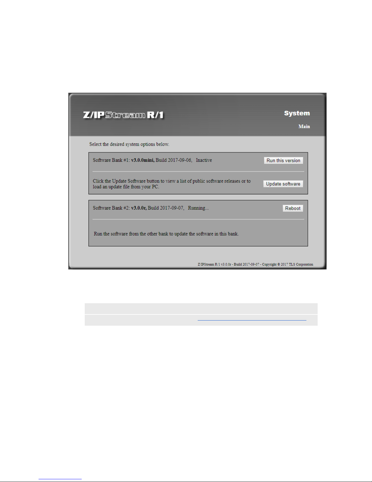
The system page can be accessed to either switch the firmware bank of the Z/IPStream R/1, or to reboot the unit.
The System Web interface will also allow the upload of new software images.
Note:
It is good practice to schedule periodic maintenance of the Z/IPStream R/1 encoder and check for
updated software. New software can be found at http://www.TelosAlliance.com/Telos/ZIPStream-R1.
Firmware is delivered via a single compressed .tgz file (it may be delivered within a .zip file from the website; if so,
unzip to access the .tgz file). From the system page of the web interface, the “Update Software” button will bring up
a file browser where the new firmware image file can be updated to the software bank. Once uploaded, Z/IPStream
R/1 can be rebooted to the new software bank. All existing configuration options will remain intact.
Page 53
44 | Section 4
Advanced Options
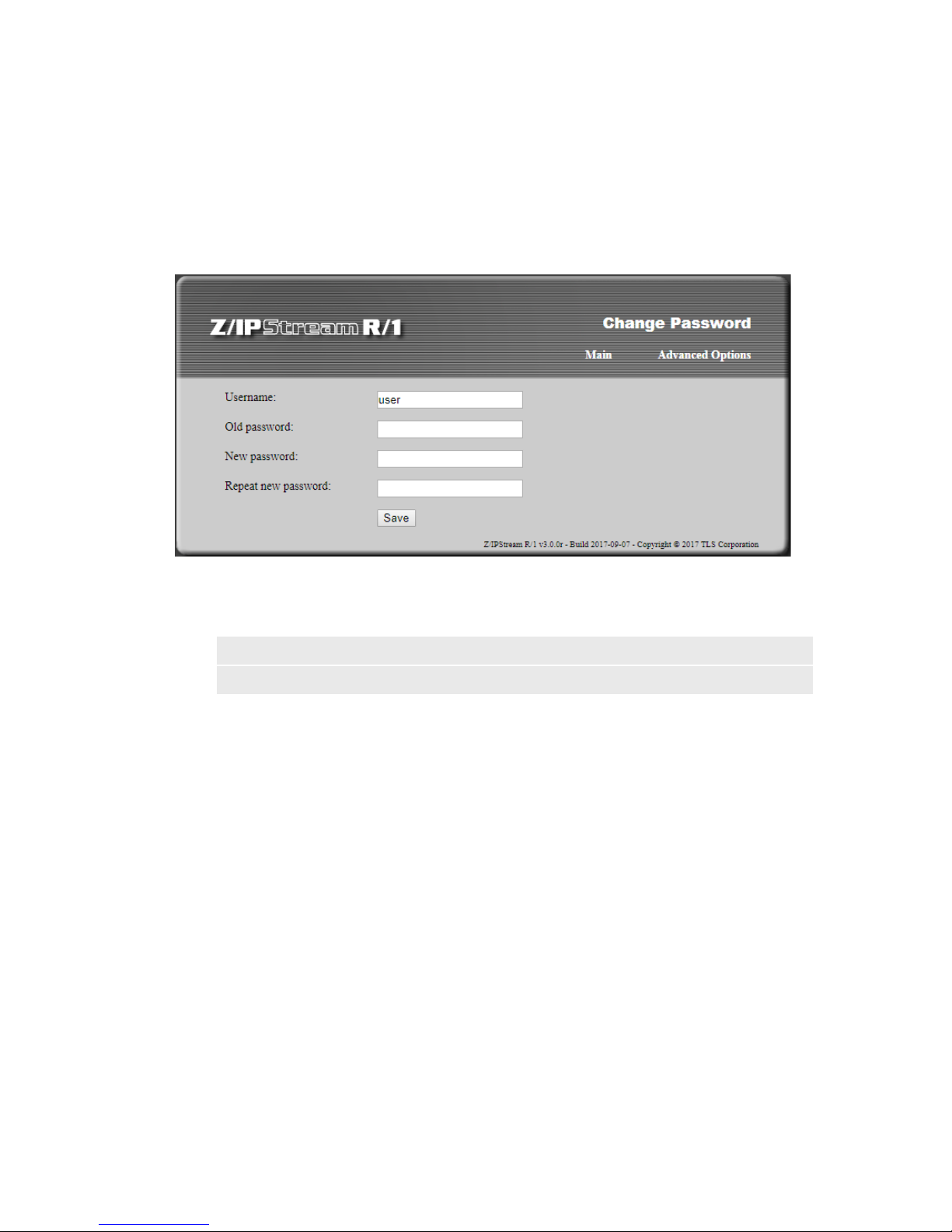
Change web interface username/password
The default username/password is user without password and admin/Telos.
NOTE:
For security reasons, it is very important to change the default login credentials. Failure to do so
may give others access to your Z/IPStream R/1.
Page 54
Z/IPSTREAM R/1 CONFIGURATION | 45
Logs/Date Time
Date/Time
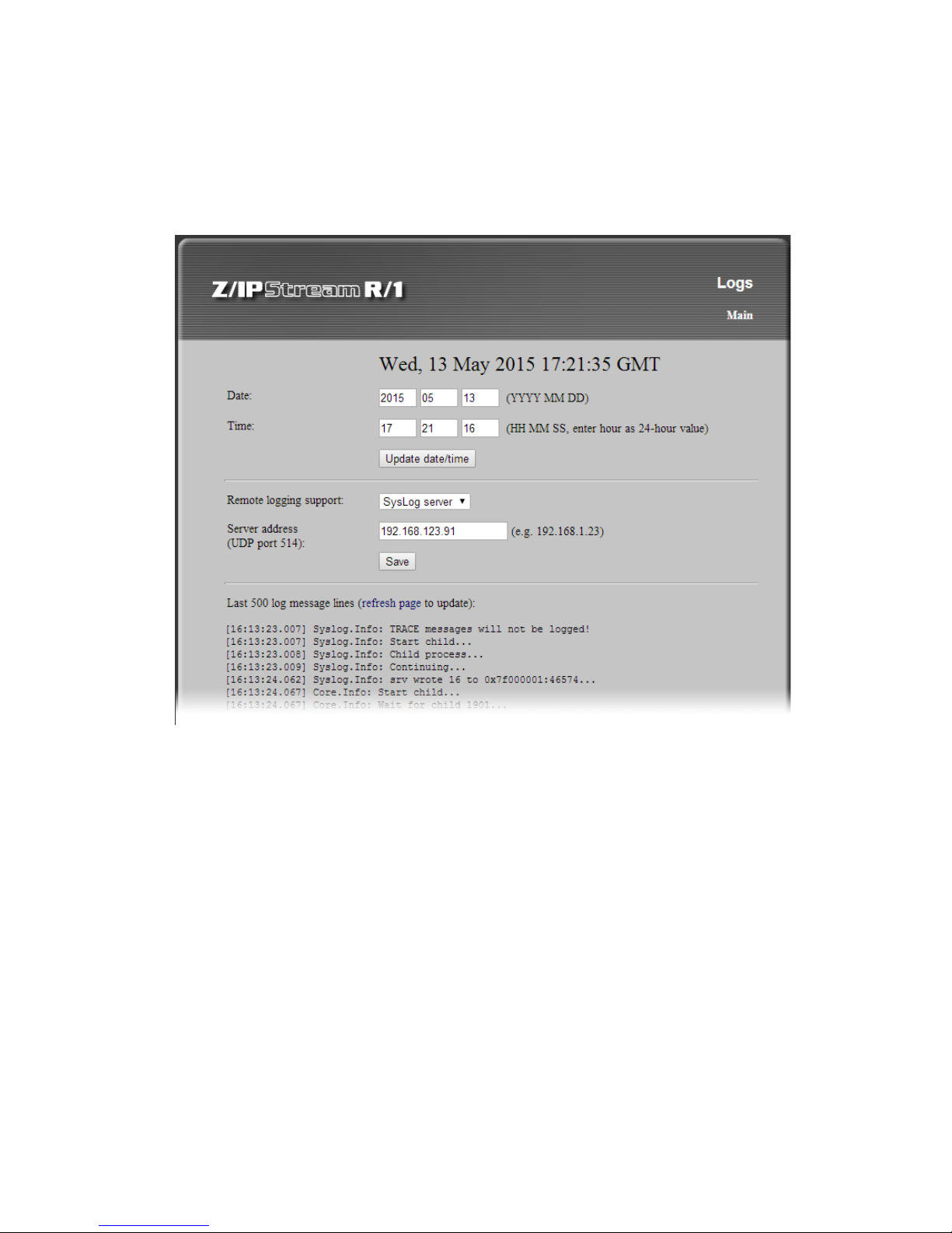
If required, it is possible to reset the Z/IPStream R/1 system time from the Logs menu.
Logs
To help troubleshooting problems, Z/IPStream R/1 allows to view last 500 system log messages when the web
interface control panel is used. If a problem occurs (cannot connect to the streaming server, etc.), log messages
should be reviewed before any Z/IPStream R/1 reboots because the log messages are deleted when the unit reboots.
If more than 500 log message lines must be reviewed it is possible to set up a SysLog compatible server on another
computer and forward log messages to this server by entering its IP address in the Z/IPStream R/1 logs section.
This allows all new log messages to be sent to the remote SysLog server to assist with system setup and diagnosis.
Syslog Server
Assign the IP address of a computer running a syslog server. All logs written to the Z/IPStream R/1 syslogs will also
be written at the same time to the syslog server assigned.
A syslog server will present logs as they are generated which can assist with setup and diagnosis. Metadata setup
especially benefits from use of the real-time syslog server.
Page 55
46 | Section 4
Ping Service
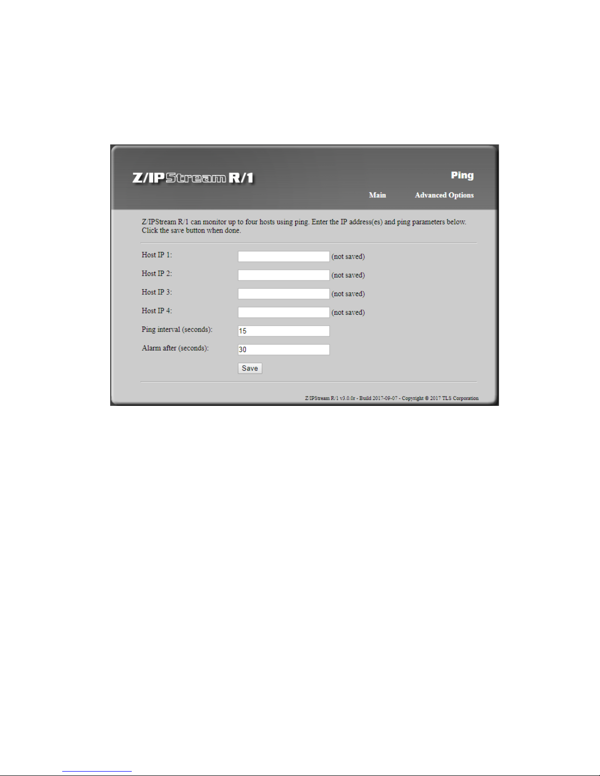
The ping service provides a means to test connectivity to certain IP addresses from the Z/IPStream R/1. This can
be useful in diagnosing connection issues from the Z/IPStream R/1 to remote servers. Ping results will display
both in the Web interface and in syslog as pinger events.
pinger.Warning: Host 192.168.1.200 failed to respond to pings after 15 sec!
Host IP
Specify up to four (4) separate IP addresses to test for ping response.
Ping Interval
Specify the interval in seconds to wait between ping attempts.
Alarm after
Trigger an alarm after a specified number of seconds of failed attempts. Must be equal to or larger than the Ping
interval.
The ping service is not configurable via the front panel.
Page 56
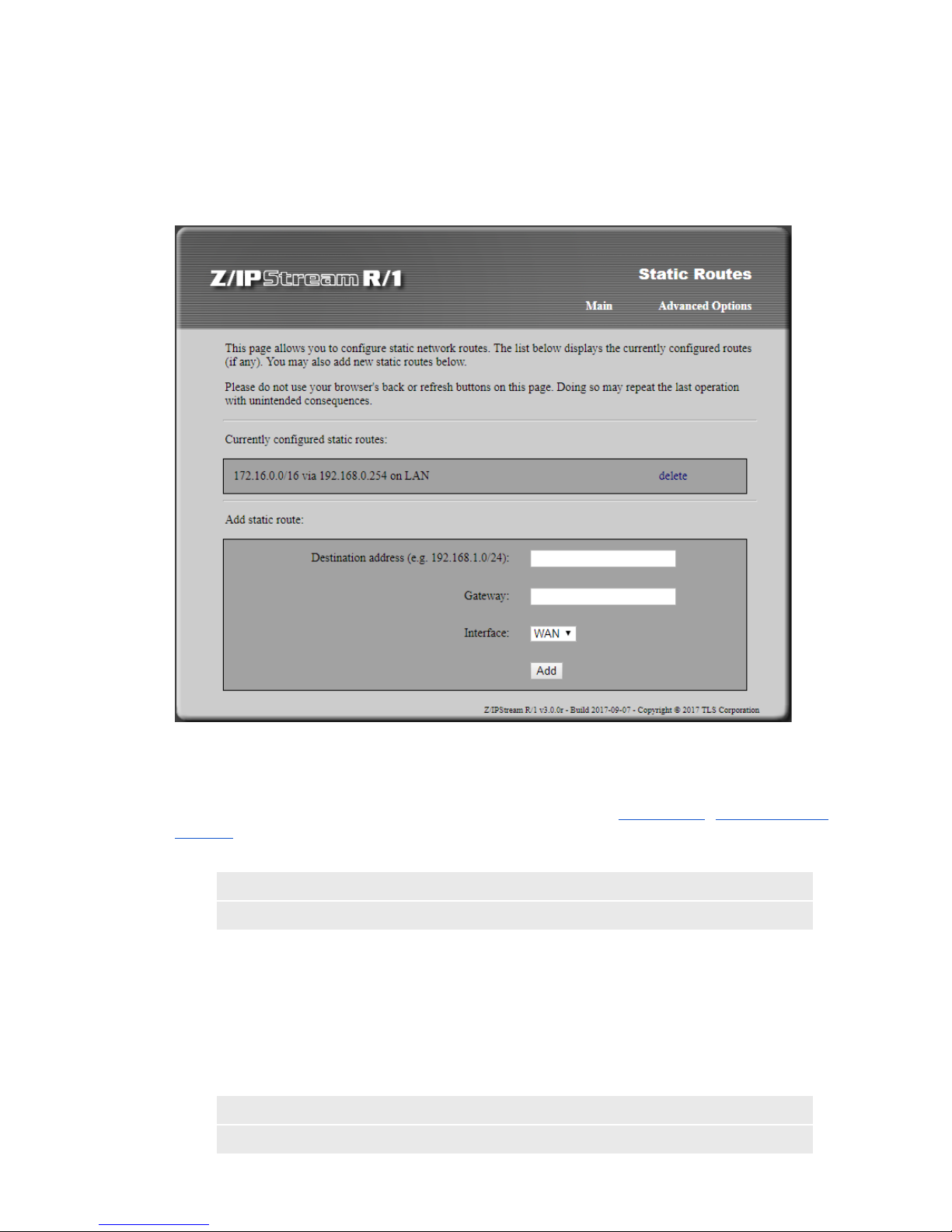
Z/IPSTREAM R/1 CONFIGURATION | 47
Congure Static Routes
Static Routing allows path selection for specific connections. A static route allows explicit specification of the
gateway and the network port (WAN or LAN).
Destination Address
Destination address can be expressed as an IP address or a network range in CIDR notation [cidr/flsm supernet
calculator]. IE 192.168.0.0/24 expresses the same information as 192.168.2.0 : 255.255.255.0 in network speak.
Note:
If a single IP address is entered, Z/IPStream R/1 will append the IP address with /32 to indicate a
single IP address in the range.
Gateway Address
A gateway is an IP address of a router, or a device which can speak to multiple networks.
Interface
Interface specifies which physical network connection the Z/IPStream R/1 should use for this communication.
LAN and WAN refer to the two back-panel network ports.
Note:
The Gateway Address must be within the range specied for the selected port (as per the Z/
IPStream R/1’s Network conguration) or the route will not be accepted.
Page 57
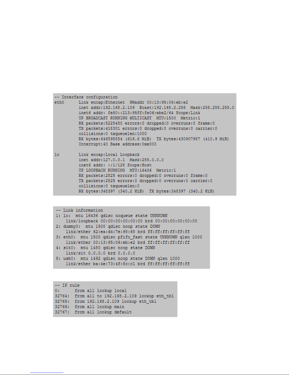
48 | Section 4
View network diagnostics
Network diagnostics will present the standard Linux output of network configurations. No user functions are
included.
Interface conguration
Link information
IP rules
Page 58
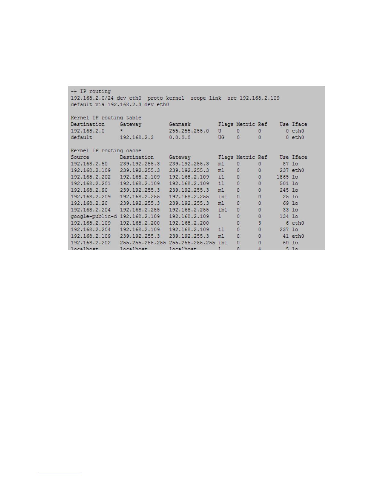
Z/IPSTREAM R/1 CONFIGURATION | 49
IP routing
Page 59
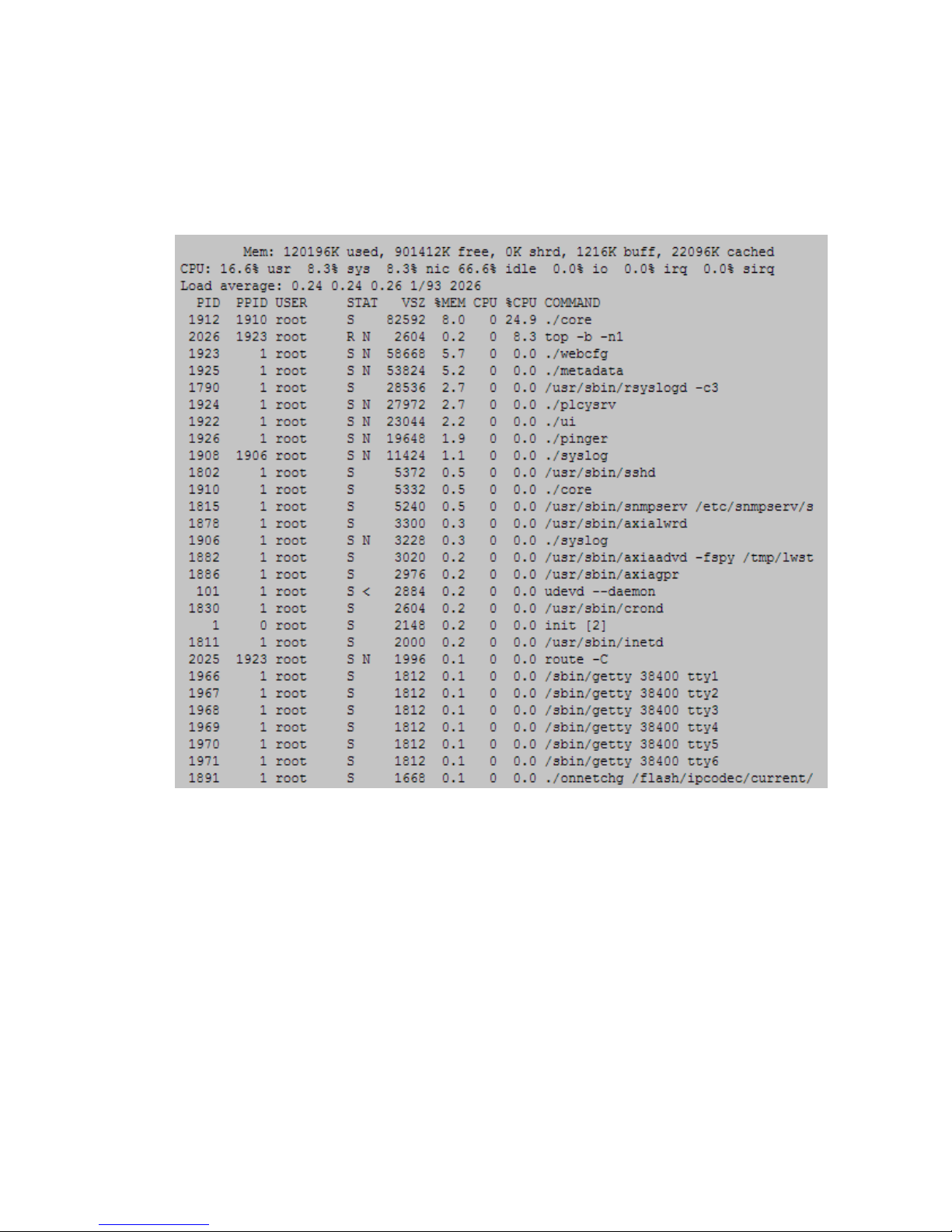
50 | Section 4
View memory usage diagnostics
The memory usage page is based on the standard Linux tool top. This presents a list of all processes in the CPU and
can be very helpful in debugging rogue processes. No user functions are included.
Page 60
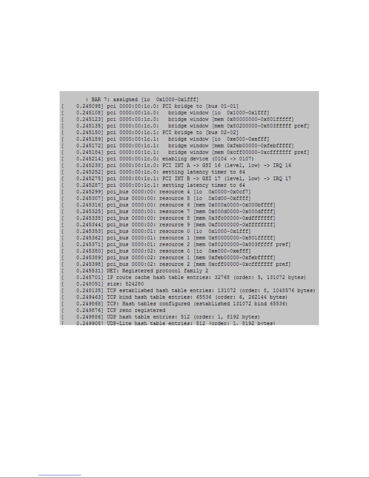
Z/IPSTREAM R/1 CONFIGURATION | 51
View system diagnostics
System diagnostics presents the output of the Linux dmesg. This can be helpful in diagnosing startup or other
system-level issues. No user functions are included.
Page 61
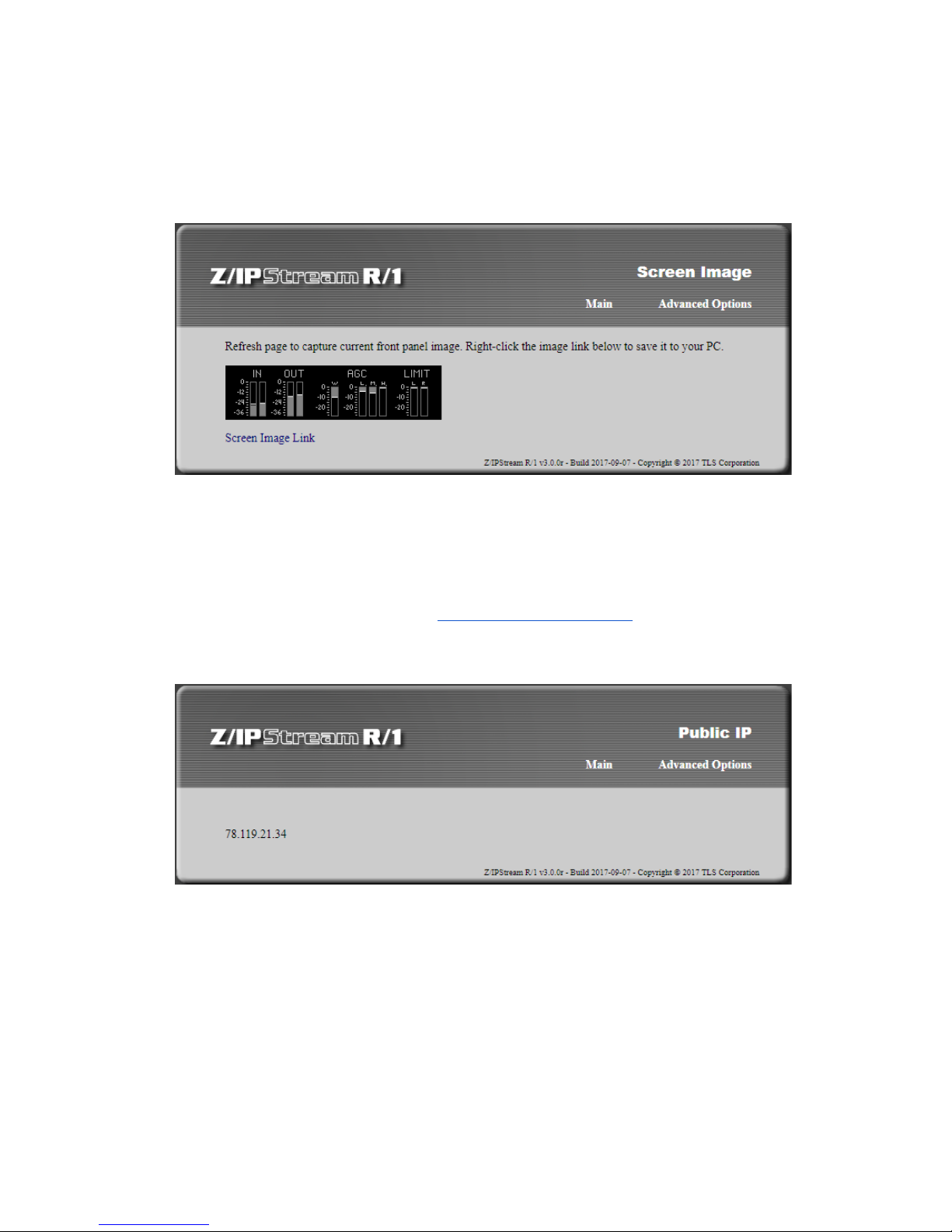
52 | Section 4
View front panel image
View front panel image will present the same image as what is currently displayed on the unit front panel. A direct
link is included on this page. No user functions are included.
Display public IP (works only if DNS is congured)
Display public IP will return a simple HTML page with nothing more than the public IP address of the routed IP
network. Since this tools refrerences against http://whatismyip.akamai.com/, failure of this command can be an
indicator of an improperly or un-configured DNS entry under the Z/IPStream R/1’s Network Settings. If in doubt,
Google’s public DNS servers can be used @ 8.8.8.8 and 8.8.4.4.
Page 62
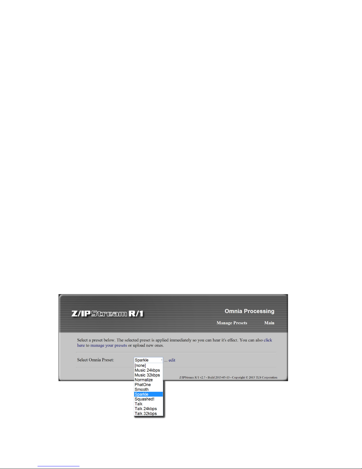
OMNIA PROCESSING | 51
5
Omnia Processing
The dynamics processing algorithms in use in the Z/IPStream R/1 are based upon Omnia Audio’s highly successful
Omnia.3net, a hardware-based DSP audio processor.
Z/IPStream R/1 employs the following Omnia processing architecture:
♦ Input
♦ Wideband AGC
♦ 3 Band Combined Compressor/Limiter
♦ Adjustable Bandwidth Low-pass Filter
♦ Final Look-Ahead Limiter
♦ Output
♦ Processing Preset Editor/Preset Management
All audio processing adjustments are performed in the Preset Editor, which is only available via the web interface. A “preset” represents all of the control values for each control in the Omnia processor. When a preset is chosen for the processor,
control values for the processor’s settings are loaded into the processing structure and applied to the input audio.
Presets allow different processing setups to be loaded into the processor. Factory presets have been provided as starting
points for customizing your sound.
It is possible to gain dramatic sonic improvement from Z/IPStream R/1’s Omnia processing right away using one of the
factory presets. Start by selecting one from the “Omnia Processing” menu and then click “...edit” to bring up the Preset
Editor.
Page 63

52 | Section 5
Preset Editor
Using the Preset Editor, it is possible to customize the chosen preset to suit your own aural requirements.
Note: Be sure to click “Save” in the upper-right hand corner of the editor window when you are finished to save
your changes. If you do not, they will be lost when the unit is rebooted. To revert to the preset’s original values,
press cancel or change preset in Omnia Processing page.
Processor Adjustment Overview
1. Start with a factory preset and adjust processor values in small increments.
2. Listen to the post-processed audio, ideally through the codec to be used, then adjust, and listen again. Aural
evaluation should occur over time, not in short moments.
3. While making changes to the system, adjust in small increments. Do not make too many different adjustments all at once. Multiple adjustments at once can make for more difficult determination of what affected
an aural change. Make changes in increments of no more than +0.5 dB or -1 dB, or in 1 or 2 step increments.
Turn functions on and off to better determine their effect on the audio.
4. Sleep on it. Spend time adjusting and then listening, and when the system gets to a point where it sounds
good, stop. When making changes to processing, ears become less sensitive to the adjustments. Spreading
the adjustment period over a number of days is recommended.
The following section will detail each control if you’d like to customize one of the factory presets to get your own
custom sound.
If you are using a factory preset as-is, please read the “Input” and “Output” adjustment sections as these are very
important for proper operation and sound quality.
Processor Adjustment
Bypass
The Bypass control (which appears in each menu), when turned ON, will completely bypass all processing,
effectively connecting the input directly to the output. Bypass control state will not be saved. To bypass processing,
please select “[none]” processing preset.
Page 64
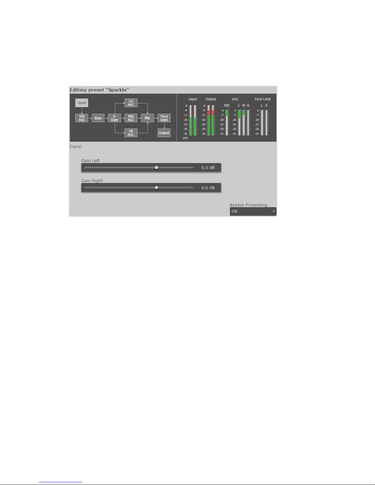
OMNIA PROCESSING | 53
Input
Proper input gain is essential for optimum processing.
Gain
Set the “Gain Left” and “Gain Right” controls so that the peak-reading Input meters are peaking “just into the red”
at -12 dBFS with normal “0VU” program audio playing.
Page 65
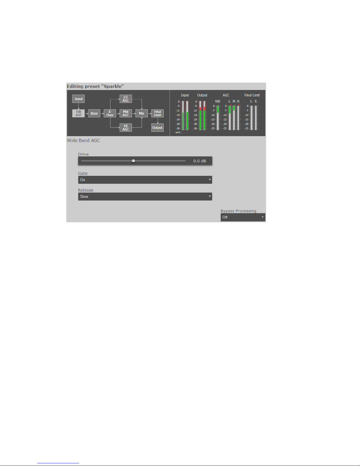
54 | Section 5
WB AGC
The Wide-Band AGC performs overall gain-riding to the input signal over a 30dB range. It acts like an automated
“hand on the pot”, keeping the overall level to the 3-Band compressor/limiter nice and consistent.
Drive
Once the Input Gain is set, you can adjust the Wide-Band AGC Drive if desired. This is measured using the “WB”
gain-reduction meter. This meter reads from the top down where “0” is no gain-reduction at all. Normally, this
should read down to between about 10-15dB with normal “0VU” program audio playing. this will allow room both
above and below for automatic gain adjustment.
Gate
This is a silence gate that freezes the gain when silence is detected to help keep noise from being brought up during
program pauses. The normal setting is “On” but the silence gate can be defeated by setting this control to “Off” if
desired.
Release
This controls the overall speed of operation of the WB AGC. “Slow” will preserve more of the natural dynamic
range in the program material.. “Fast” will bring up lower level passages faster and react faster to program level
changes. “Medium” is a nice compromise between the two.
Page 66
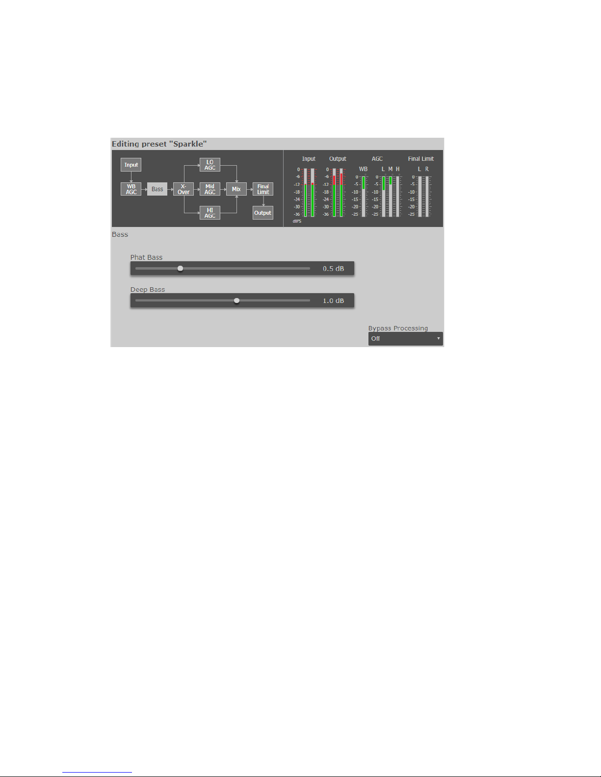
OMNIA PROCESSING | 55
Bass
Some bass boost is normally used when processing to balance out the spectrum and add some “punch.” These two
controls adjust the amount of the Z/IPStream R/1’s bass enhancement section. They are more than just simple
EQ’s. If your source material has it, Z/IPStream R/1 will put it in the mix, and with muscle!
Making changes to the bass is done using the following parameters, and for maximum effectiveness, in the order
listed: (NOTE: Settings of “0.0” apply no bass boost.)
1. In the Bass menu, increase the amount of Deep Bass boost to taste. This is the lowest “kick drum” bass. so be
sure to monitor with speakers or headphones that can reproduce bass below 80Hz.
2. In the Bass menu, increase the amount of Phat Bass boost to taste. This special bass effect can help smaller
speakers sound like they have more bass than they really do.
3. Increase the drive to the LF AGC in the LO AGC screen.
4. Speed up the release times of the LO AGC section.
5. Slightly increase the low control in the mixer section.
When processing, moderation is the key. If all of the above steps are utilized in the pursuit of more bass, severe
low frequency over-enhancement can occur. Excessive bass boost can produce the illusion that the presence and
high frequencies have been lost. They are still there, but are being acoustically masked by the lower frequencies.
Generally, an increase in the Bass menu’s bass boost functions alone will provide more than sufficient enhancement
to the low end.
Phat Bass
Phat bass widens the higher low-end frequencies in an effort to expand bass sound on smaller playback speakers.
Deep Bass
Deep bass focuses on frequencies of 80hz and below.
Page 67
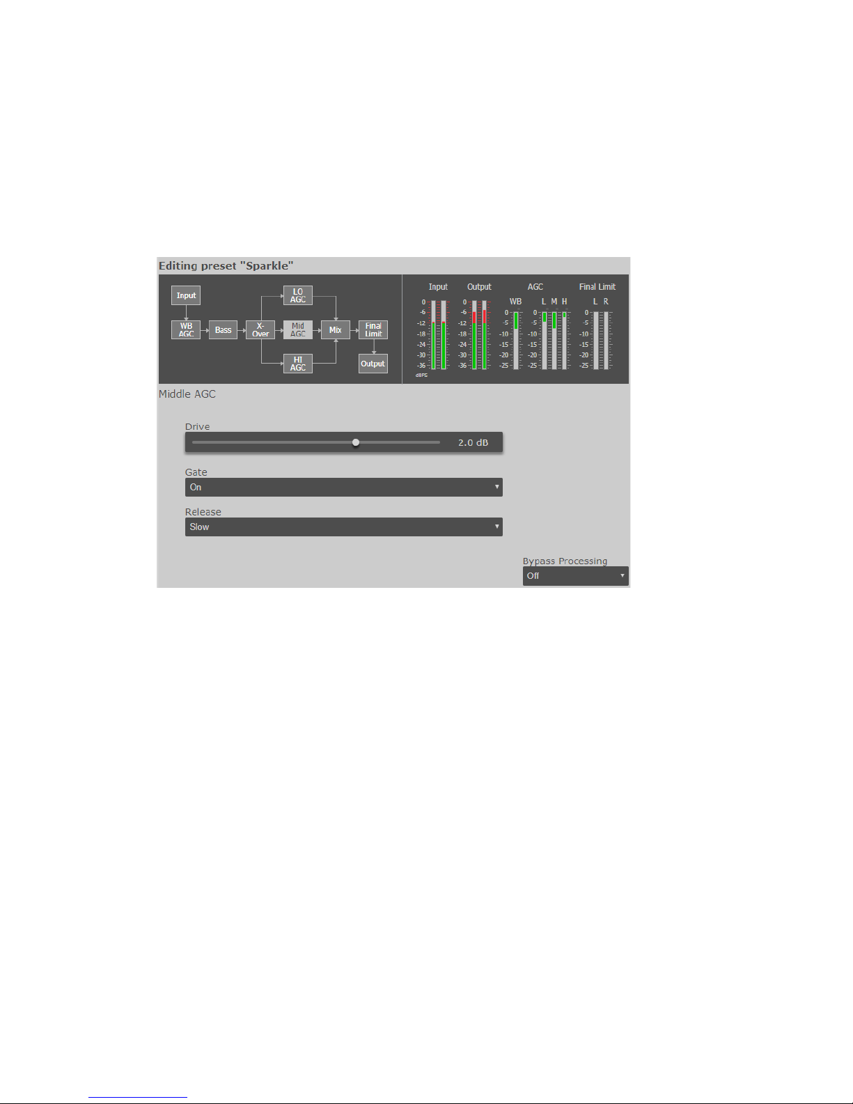
56 | Section 5
X-Over
The X-Over (crossover) splits the audio from the WB AGC into 3 frequency bands so each band can be optimally
processed. The three bands are: Lo (bass) Mid (midrange - voice and solo instruments) and Hi (treble). There
are no adjustable controls in the crossover section.
Low,Mid,Hi AGC
Each band has a Drive, Gate and Release control, similar the the WB AGC.
Drive
The Drive control adjusts the volume of the audio from the crossover into the compressor/limiter for the selected
band. Higher settings will drive the selected band into more gain-reduction. Some EQ can also be done with the
Drive controls if one band is adjusted differently than the others. Start by setting them equally though.
More drive will provide a denser, more compressed (but louder) sound. Less drive will provide a more natural and
“open” sound.
Generally, you will see these meters move faster than the WB AGC. Generally, between 5 and 10 dB of gain-reduction is a good nominal amount. Note that the Hi band may show less gain-reduction than the others. This is normal.
Gate
This is a silence gate that freezes the gain when silence is detected to help keep noise from being brought up during
program pauses. The normal setting is “On” but the silence gate can be defeated by setting this control to “Off” if
desired.
Release
This controls the overall speed of operation of the compressor/limiters. “Slow” will preserve more of the natural
dynamic range in the program material.. “Fast” will react faster to program level changes. “Medium” is a nice
compromise between the two.
Page 68
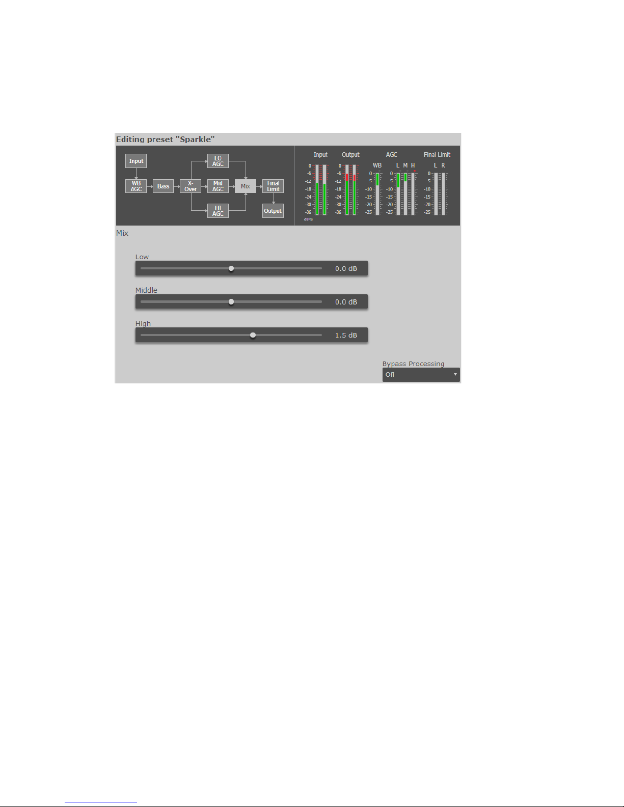
OMNIA PROCESSING | 57
Mix
The final mixer level controls set the output level of each of the 3 compressor/limiter bands into the final lookahead limiter. Note that it is possible to reduce the level below “0” as well as increase it.
Level [Low, Middle, High]
While some EQ adjustment can be done at this stage, be careful not to turn one band’s mix level up too much higher
than the others. This will cause too much of that band’s signal to hit the final limiter, causing possible undesired
effects such as overload (excessive limiting of one band’s audio) or pumping.
It is generally better to leave these set at their default settings and use the Bass and Drive controls to EQ the sound
to your liking.
Then, if further correction is required, you can reduce the level of a particular band here if needed, such as reducing
the High mixer if the audio sounds too bright.
Try to use the mixer only to reduce rather than boost as a rule-of-thumb.
Page 69
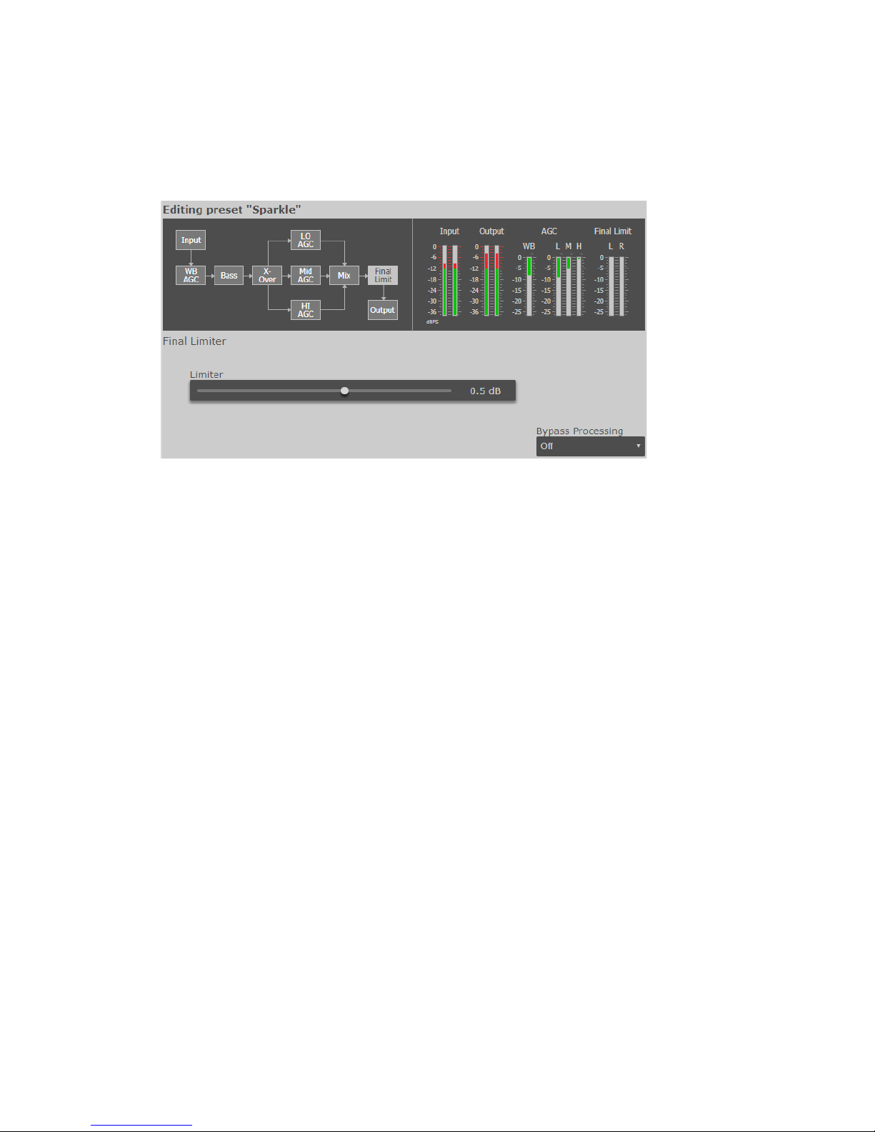
58 | Section 5
Final Limiter
The final limiter is a fast, look-ahead peak limiter that provides final peak control to the processed audio.
Limiter
Generally, set the Limiter level control until you see about 2 to 4dB of gain-reduction on the Final Limit meters with
normal program audio playing.
Too low a setting will decrease loudness while too high a setting can sound too dense and over-processed.
Page 70
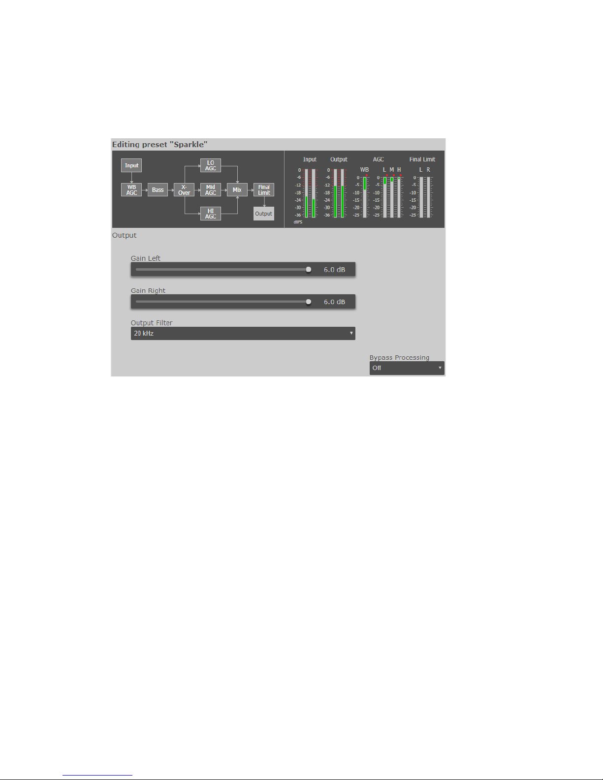
OMNIA PROCESSING | 59
Output
Gain [Left & Right]
The Gain Left and Gain Right controls set the final peak output level that feeds the codec. Normally, this can be set
to just under the maximum setting of 6.0dB. This setting corresponds to about 0dBFS. Normally, a setting of 5.8dB
should be fine, but be sure to listen for clipping distortion through the codec and adjust as needed.
Output Filter
Dynamics processing is an extremely useful tool for reducing audible artifacts from lossy-compression codecs.
High frequencies tend to be the first perceptible annoyances, followed by that swishy-swirly water like sound
common at lower bitrates. These artifacts can be reduced, and in some cases eliminated, when audio processing is
applied as a tool.
Generally, as codec bitrates are reduced, so is the audio bandwidth. Z/IPStream R/1 contains a selectable low pass
filter in the output section. Reducing the audio bandwidth by using a lower frequency setting can help reduce the
audible side-effects of low bitrate coding. Additionally, reducing the High band MIX setting can help.
Also, operating the HF Band in the slow release time will reduce HF density which improves intelligibility as the
encoder masking algorithm is not loaded as heavily with HF content.
Page 71
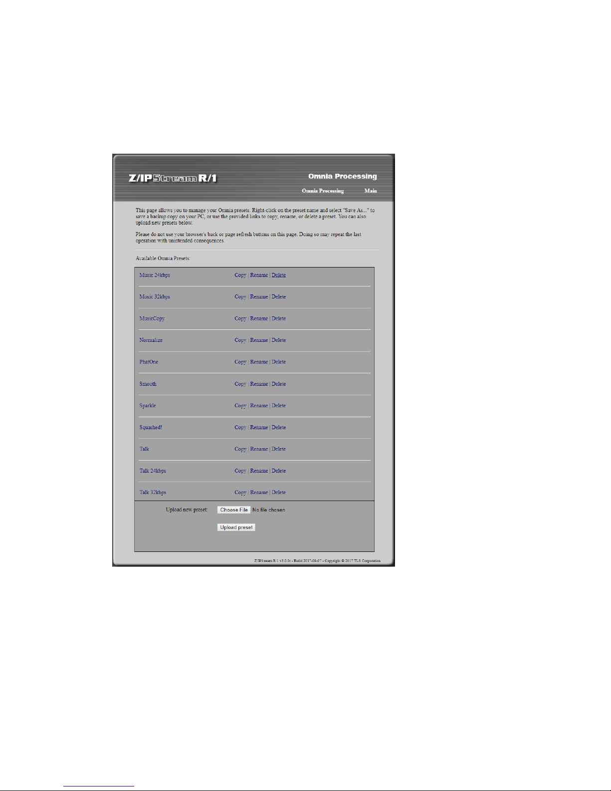
60 | Section 5
Managing Presets
From the Omnia Processing menu, click Manage Presets to open the preset management window.
In the example shown here, we made some changes to the PhatOne preset and then clicked “Save”.
Now, here in the Manage Presets window you will see that the PhatOne preset line has an additional choice:
“Restore”. If we were to click on “Restore” now, before saving a copy, the original factory PhatOne preset will be
restored and the changes we made would be lost.
So if you do make some changes to a preset and save them, it would be a good idea to click “Copy” to save the preset
with your changes to a new name. This will create a user preset with that name.
Once that is done, you can Restore the factory preset and can compare it to the new user preset that contains the
changes you made from the original.
Note that the Restore option will only appear when you save custom changes to a factory preset or delete a factory
preset. This means that factory presets can always be restored, even if you delete them to remove them from the
preset list. This IS NOT the case for user presets. Deleting a user preset is final.
Page 72

WARRANTY | 61
A1 Telos Alliance Warranty
Telos Alliance Limited Warranty
Telos Alliance Radio Division has an industry-leading five-year warranty.
As a company, we are commited to our products and the pursuit of providing
better quality to our customers.
Find the Warranty online at www.telosalliance.com/warranty.
Page 73

SPECIFICATIONS | 63
A2 Specications
Audio Coding
Codecs:
♦ MP3: 16 to 320 kbps
♦ AAC-LC: 24 to 320 kbps
♦ HE-AAC: 24-96 kbps
♦ HE-AAC v2 (aacPlus): 24-96 kbps
AAC Transport Modes:
♦ ADTS
♦ ADTS-CRC
♦ ADIF
♦ RAW METADATA FORMATS:
♦ Character Parser Sample
♦ Line Parser Sample
♦ Nexgen Audio Sense
♦ Simian Template 1
♦ XML Parser Sample
♦ XML-Jazler
♦ XML-Jazler2
♦ XML-MediaTouch
♦ XML-MediaTouch2
♦ XML-Sample2
♦ XML-Zetta
♦ User-definable
Page 74

64 | Section 7
Analog Audio Input
♦ Analog: Balanced XLR, +4 dBu
♦ Input Impedance: 6K Ohm differential
♦ Analog to Digital Converter: 24bits
Analog Audio Output
♦ Analog: Balanced XLR
♦ Output Clipping: + 22dBu
♦ Output Impedance: 50 Ohm differential
♦ Digital to Analog Converter: 24bits
Digital Audio Inputs and Outputs
♦ Reference Level: +4 dBu (-20 dB FSD)
♦ Impedance: 110 Ohm, balanced
♦ Signal Format: AES3 (AES/EBU)
♦ AES3 Input Compliance: 24-bit with sample rate conversion
♦ AES3 Output Compliance: 24-bit
♦ Internal Sampling Rate: 48 kHz
♦ Input Sample Rate: 32 kHz to 192 kHz
♦ Output Sample Rate: 48 kHz
♦ A/D Conversions: 24-bit, Delta-Sigma, 256x oversampling
♦ D/A Conversions: 24-bit, Delta-Sigma, 256x oversampling
♦ Digital: Livewire AoIP, via LAN port
Audio Performance
♦ THD+N: < 0.03% @ +12dBu, 1 kHz Sine
♦ Freq Response: +/- 1dB 25– 20 kHz
♦ Head Room: 18dB
♦ Dynamic Range: > 87dB Unweighted > 90 dB “A” Weighted
♦ Crosstalk: > 80 db
Remote Control
♦ LAN via built-in Webserver
Page 75

Power
♦ Internal supply, 85–250 VAC auto-switching, 50–60 Hz.
♦ Power consumption: 14.2 Watts
Dimensions
♦ 19” (48.3 cm) standard rack mounting front panel
♦ 1.75” (4.5 cm) height, 6.5” (16.51 cm) depth
♦ Shipping Weight: 8 lbs. (3.62 kg)
Z/IPStream R/1 Self Test
1. Press and hold the Headphone Volume Knob in during power up until the screen activates.
2. Release Headphone Volume Knob and then press the Control Knob.
3. Activate all front panel controls to test function.
4. Once complete, the “Frontpanel” status will confirm OK to indicate controls are good.
Page 76

1241 Superior Ave. • Cleveland, Ohio, 44114, USA • +1.216.241.7225 • TelosAlliance.com
© 2017 TLS Corp. The Telos Alliance.® All Rights Reserved. C17/1/19014
 Loading...