

Page 1
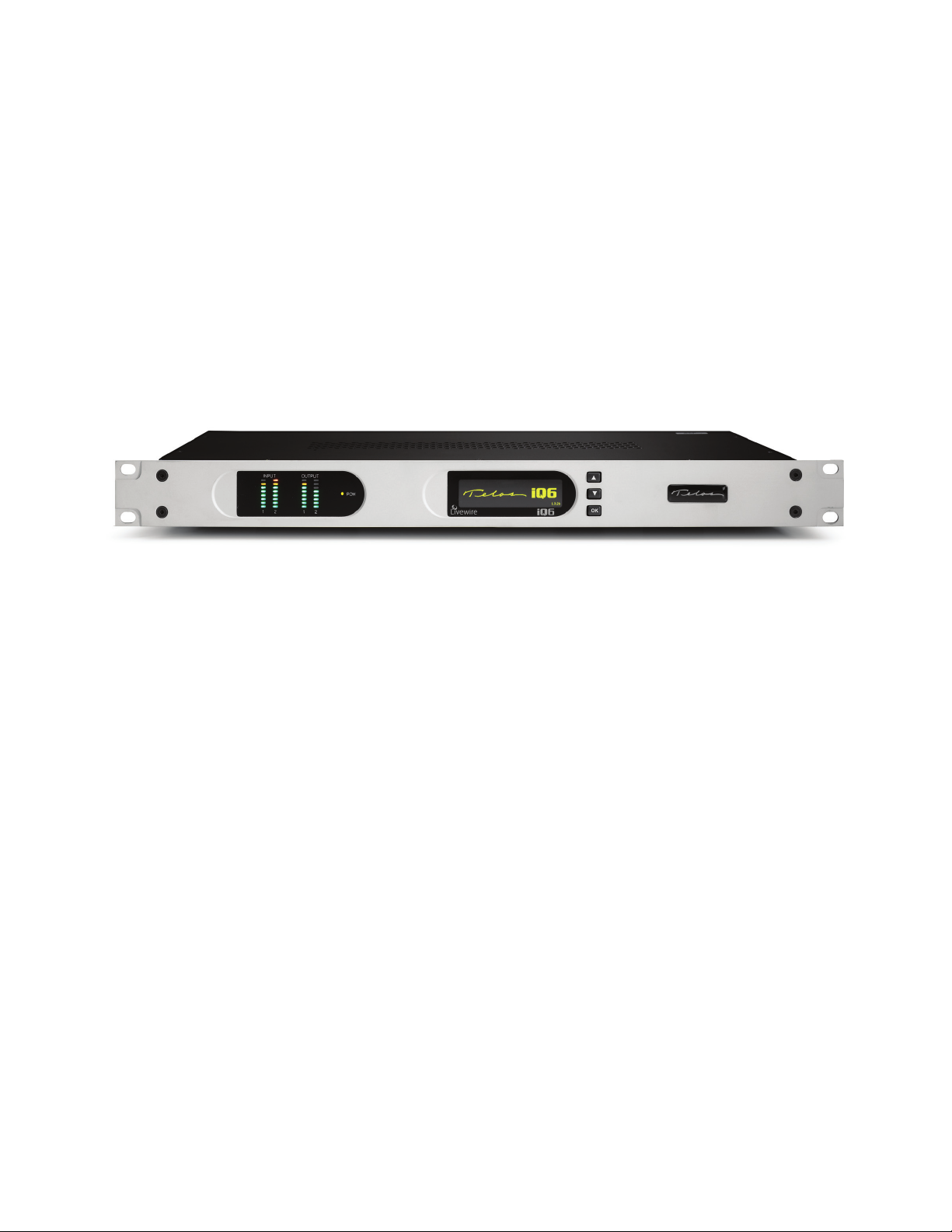
TELOS iQ6
Multi-Studio IP Phone Interface System
USER’S MANUAL
Manual Version SC 1.01 20 October, 2011
part#: 1490-00072-001
Page 2

iQ6 Manual
© 2011 TLS Corporation. Published by Telos Systems/TLS Corporation. All rights reserved.
Trademarks
Telos Systems, the Telos logo and iQ6 are trademarks of TLS Corporation. All other
trademarks are the property of their respective holders.
Notice
All versions, claims of compatibility, trademarks, etc. of hardware and software products not made by Telos
mentioned in this manual or accompanying material are informational only. Telos Systems makes no endorsement
of any particular product for any purpose, nor claims any responsibility for operation or accuracy. We reserve the
right to make improvements or changes in the products described in this manual which may affect the product
specifications, or to revise the manual without notice.
Warranty
This product is covered by a two year limited warranty, the full text of which is included in this manual.
Updates
The operation of the iQ6 is determined largely by software. We routinely release new versions to add features and
fix bugs. Check the Telos web site for the latest. We encourage you to sign-up for the email notification service
offered on the site.
Feedback
We welcome feedback on any aspect of the iQ6, or this manual. In the past, many good ideas from users have made
their way into software revisions or new products. Please contact us with your comments.
Service
You must contact Telos before returning any equipment for factory service. We will need the serial number, located
on the back of the unit. Telos Systems will issue a Return Authorization number which must be written on the
exterior of your shipping container. Please do not include cables or accessories unless specifically requested by the
technical support engineer at Telos. Be sure to adequately insure your shipment for its replacement value. Packages
without proper authorization may be refused. US customers please contact Telos technical support at +1-216-622-
0247. All other customers should contact your local representative to make arrangements for service.
We support you...
By Phone / Fax:
You may reach our 24/7 Support Team anytime around the clock by calling +1-216-622-0247.
For billing questions or other non-emergency technical questions, call +1-216-241-7225 between 9:30 AM to 6:00
PM USA Eastern Time, Monday through Friday.
Our fax is +1-216-241-4103.
By E-Mail:
Technical support is available at [email protected].
All other inquiries at [email protected].
Via World Wide Web:
The Telos Web site has a variety of information which may be useful for product selection and support.
The URL is www.Telos-Systems.com
10 9 8 7 6 5 4 3 2 1
Page 3

Telos Systems USA
This symbol, wherever it appears, alerts you to the presence
of uninsulated, dangerous voltage inside the enclosure –
voltage which may be sufficient to constitute a risk of shock.
This symbol, wherever it appears, alerts you to important
operating and maintenance instructions. Read the manual.
Telos Systems
1241 Superior Avenue E
Cleveland, OH 44114 USA
+1-216-241-7225 (phone)
+1-216-241-4103 (fax)
+1-216-622-0247 (24/7 Technical Support)
Notices and Cautions
CAUTION:
THE INSTALLATION AND SERVICE INSTRUCTIONS IN THIS MANUAL ARE FOR USE BY QUALIFIED
PERSONNEL ONLY. TO AVOID ELECTRIC SHOCK, DO NOT PERFORM ANY SERVICING OTHER THAN
THAT CONTAINED IN THE OPERATING INSTRUCTIONS UNLESS YOU ARE QUALIFIED TO DO SO. REFER
ALL SERVICING TO QUALIFIED PERSONNEL.
WARNING:
TO REDUCE THE RISK OF ELECTRICAL SHOCK, DO NOT EXPOSE THIS PRODUCT TO RAIN OR MOISTURE.
USA CLASS A COMPUTING DEVICE INFORMATION TO USER. WARNING:
This equipment generates, uses, and can radiate radio-frequency energy. If it is not installed and used as directed by
this manual, it may cause interference to radio communication. This equipment complies with the limits for a Class
A computing device, as specified by FCC Rules, Part 15, Subpart J, which are designed to provide reasonable protection against such interference when this type of equipment is operated in a commercial environment. Operation
of this equipment in a residential area is likely to cause interference. If it does, the user will be required to eliminate
the interference at the user’s expense. NOTE: Objectionable interference to TV or radio reception can occur if
other devices are connected to this device without the use of shielded interconnect cables. FCC rules require the use
of shielded cables.
CANADA WARNING:
“This digital apparatus does not exceed the Class A limits for radio noise emissions set out in the Radio Interference
Regulations of the Canadian Department of Communications.”“Le present appareil numerique n’emet pas de
bruits radioelectriques depassant les limites applicables aux appareils numeriques (de Class A) prescrites dans le
reglement sur le brouillage radioelectrique edicte par le ministere des Communications du Canada.”
Page 4

iv |
Table of Contents
We support you... . . . . . . . . . . . . . . . . . . . . . . . . . . . . .i
A letter from our CEO . . . . . . . . . . . . . . . . . . . . . . . . . . vii
1 Introduction 1
1.1 The iQ 6 . . . . . . . . . . . . . . . . . . . . . . . . . . . . . . . 1
1.2 Features. . . . . . . . . . . . . . . . . . . . . . . . . . . . . . . 1
1.3 Integrated Service Digital Networks . . . . . . . . . . . . . . . . . . 2
2 Installation 5
2.1 Getting started . . . . . . . . . . . . . . . . . . . . . . . . . . . 5
2.2 TELCO . . . . . . . . . . . . . . . . . . . . . . . . . . . . . . . . 5
2.2.1 Plain old telephone service – POTS . . . . . . . . . . . . . . . . 5
2.2.2 Integrated Service Digital Networks – ISDN . . . . . . . . . . . . 6
2.2.3 Integration with a PBX . . . . . . . . . . . . . . . . . . . . . 8
2.3 Basic Web Interface Conguration . . . . . . . . . . . . . . . . . . . 9
2.4 Client Conguration . . . . . . . . . . . . . . . . . . . . . . . . . 11
2.4.1 Axia iQ surface . . . . . . . . . . . . . . . . . . . . . . . . . 11
2.4.2 VSet . . . . . . . . . . . . . . . . . . . . . . . . . . . . . . 12
2.4.3 VX Producer . . . . . . . . . . . . . . . . . . . . . . . . . . 12
3 User Operation 13
4 Detailed Conguration & Reference 21
4.1 Front Panel . . . . . . . . . . . . . . . . . . . . . . . . . . . . . 21
4.1.1 Audio Menu . . . . . . . . . . . . . . . . . . . . . . . . . . 22
4.1.2 Telco Menu. . . . . . . . . . . . . . . . . . . . . . . . . . . 23
4.1.3 System Menu . . . . . . . . . . . . . . . . . . . . . . . . . 24
4.2 Web User Interface . . . . . . . . . . . . . . . . . . . . . . . . . . 24
4.2.1 Status . . . . . . . . . . . . . . . . . . . . . . . . . . . . . 25
4.2.2 Telco . . . . . . . . . . . . . . . . . . . . . . . . . . . . . 26
Page 5

IQ6 MANUAL | v
4.2.3 Audio . . . . . . . . . . . . . . . . . . . . . . . . . . . . . 30
4.2.4 Show Setup . . . . . . . . . . . . . . . . . . . . . . . . . . 33
4.2.5 Livewire Audio . . . . . . . . . . . . . . . . . . . . . . . . . 34
4.2.6 Livewire GPIO . . . . . . . . . . . . . . . . . . . . . . . . . 35
4.2.7 Livewire QoS . . . . . . . . . . . . . . . . . . . . . . . . . . 35
4.2.8 System . . . . . . . . . . . . . . . . . . . . . . . . . . . . 36
4.2.9 Backup . . . . . . . . . . . . . . . . . . . . . . . . . . . . 38
5 Technical Data & Troubleshooting 39
5.1 Overview . . . . . . . . . . . . . . . . . . . . . . . . . . . . . . 39
5.2 System Software & Firmware . . . . . . . . . . . . . . . . . . . . . 39
5.3 General Troubleshooting . . . . . . . . . . . . . . . . . . . . . . . 39
5.4 Troubleshooting ISDN Problems . . . . . . . . . . . . . . . . . . . . 41
5.5 Replaceable Modules and Hardware Servicing . . . . . . . . . . . . . 44
5.6 ISDN Cause Phrases/Values . . . . . . . . . . . . . . . . . . . . . . 45
5.7 Livewire Audio Troubleshooting . . . . . . . . . . . . . . . . . . . . 52
6 Specications 55
7 Warranty and Application Caution 57
Page 6

Page 7

A LETTER FROM OUR CEO | vii
A Letter from our CEO...
“What if?” A singularly great question, because it opens the
door to so many other questions and ideas. Those who ask
it are sometimes called dreamers, as if that were somehow
bad, but history has often proven dreamers to be the avatars
of new and exciting things.
eliminate the age-old problem of feedback in open-speaker
environments. And the prize of using the public Internet for
remote connections as reliable as those of switched circuits
is within broadcasters’ grasp, thanks to ever more sophisticated coding algorithms.
“What if?” was the query asked by Steve Church that led
to the start of Telos Systems. In 1984, Steve – then a young
broadcast engineer and part-time talk show host – wondered whether emerging Digital Signal Processing (DSP)
technology might be useful to clean up the terrible caller
audio then the norm at radio stations. The result of asking it
was the Telos 10, the world’s first digital telephone hybrid,
a product that changed the face of radio forever.
Looking back at Telos history, “What if?” is found at the
root of many more technologies broadcasters have since
made ubiquitous. “MP3 bit rates are perfectly matched
to the bandwidth of ISDN; what if we combined them?”
“What if we built a box that let radio stations stream audio
on the Internet?” “What if we could use Ethernet to treat
audio as data and move it around the radio station in real
time?” (By the way, if you recognized the answers to those
questions as the Zephyr ISDN codec, AudioActive MPEG
encoder and Livewire IP-Audio standard, give yourself a
cookie.)
Today, as technology roars ahead, we’re constantly seeking
new ways to apply it to the problems of everyday broadcasting. Voice over IP (VoIP) is particularly compelling for
its ability to packetize high-quality phone calls and direct
them anywhere in the broadcast plant using ubiquitous,
standard Ethernet as a backbone. A new digital tech called
AEC (Advanced Echo Cancellation) is helping to literally
Pioneering ideas aren’t limited just to technology, though.
We believe that investing in people pays off big, so we’ve
assembled the largest R&D team in the industry, a talented
staff of engineers, scientists and broadcast professionals.
We’re also the first and only broadcast equipment maker
with a 24/7 support team ready to offer assistance any
time of the day or night. As they say, radio never sleeps – so
neither do we.
As Telos navigates its third decade in broadcasting’s
choppy waters, the culture of innovation and creativity that
propelled Steve in the early days still guides us today. We’re
still in love with radio, still turned on by new technology,
still driven to ask “What if?” If you’re reading this, you
are too — for which we thank you, from the bottom of our
hearts.
Michael “Catfish” Dosch
CEO
Page 8

Page 9

| 1
1
Introduction
1.1 The iQ6
The Telos iQ6 is the Telco gateway for Axia’s iQ console. iQ6 combines a six line selector
and two third-generation Telos hybrids with Digital Dynamic EQ. The two hybrids are
designed to be used within a single studio for airing simultaneous callers and achieving
optimal audio quality.
Control the iQ6 from the Axia iQ console equipped with the Telco expansion frame via a producer’s PC running the VX Producer software. Take and screen calls directly via the producer’s
PC that uses the VX Producer software. All controllers function with a TCP connection and the
iQ6 provides support for twelve connections.
The iQ6 comes with a POTS or ISDN (Integrated Service Digital Network) interface. This
provides support for the connection of six lines for the two integrated hybrids.
Audio input and output is accomplished through Livewire for seamless integration to the Axia
iQ console. There are no dedicated connectors on the back panel for audio. All control and audio
passes through the Ethernet Adapter and the CAT-5e cable which connects to it.
1.2 Features
Telos introduced the first digital hybrid which increased the quality of caller audio. Over the
years, each new Telos product continues to raise the bar. The iQ6 is no exception.
♦ Third generation advanced hybrid algorithms.
♦ New symmetrical wide-range AGC and noise gate by Omnia, with adjustable gain
settings.
♦ Adjustable caller override improves performance and allows you to customize the degree
to which the announcer ducks the caller audio.
♦ DDEQ-Digital dynamic EQ™ keeps audio spectrally consistent from call to call.
♦ Separate Send level and Receive level meters for each hybrid.
♦ Worldwide disconnect signal detection (loop drop, dial tone, or reorder tone).
♦ Livewire Audio.
♦ Axia iQ console integration.
♦ Conference linking lets you set up high-quality conferencing between callers with no
external equipment needed.
Page 10

2 | Section 1
♦ Caller ID support on both ISDN and POTS lines.
♦ Support for up to twelve controllers.
♦ VX control protocol for compatibility with Telos VSet, VX Producer, and third-party call
control software applications.
1.3 Integrated Service Digital Networks (ISDN)
The iQ6 works with either traditional analog Telco lines or with ISDN (Integrated Services
Digital Network). We recommend ISDN service for telephone connections whenever possible.
There is no comparable technology for getting audio to and from the public telephone network.
We provide plenty of advice right here in this manual and live support by people with years of
ISDN experience. (Thousands of Telos ISDN interfaces and Zephyrs are deployed around the
world!) Currently, the dial-up telephone network is nearly entirely digital. Only the “last mile”
copper connections from the telephone Central Office exchange to the customer’s site remain
with the archaic analog scheme. ISDN offers us a way to link the studio directly into the Telco
digital infrastructure without the usual impairments of analog connections. iQ6 continues the
digital path with the use of the Livewire audio connection to the iQ console.
While the application of digital signal processing to the problem of separating announcer
and caller audio – pioneered by Telos and used in all of our telephone interfaces – has made
a dramatic improvement over analog-only hybrids, using digital phone lines for on-air calls
further improves performance for several reasons:
1. Exceptional send-to-receive isolation. Traditional analog phone lines multiplex both
speech directions in order to use a single pair of wires for a conversation. This causes
what’s referred to as ‘leakage’ – when the announcer’s audio is present on the hybrid
output, creating an annoying ‘hollow’ or ‘tinny’ sound. Telos digital adaptive hybrids
reduce this problem. But ISDN offers independent and separated signal paths, so our
hybrids only have to operate on the far-end analog line, if any. The result is much lower
leakage.
2. Higher send levels. We don’t have to be concerned about regulations designed to prevent
crosstalk on analog lines, so we can increase send-to-caller levels.
3. Lower distortion. The analog-digital conversion chips used in telephone central offices
are poor compared to the converters used in professional audio equipment. Fidelity
is not an important consideration when telephone equipment designers choose parts
for this function. In a professional interface for studio applications, we can afford to
design-in much better converters. Noise-shaping functions permit a larger word-length
converter to provide significantly better distortion and signal-to-noise performance.
4. Lower noise. Because they are digital, ISDN lines are not susceptible to induced noise.
Analog lines are exposed to a variety of noise and impulse trouble-causers as they snake
across town on poles and through your building. Hum is the main problem, given most
lines. Digital lines convey the bits precisely and accurately from the network to your
studio equipment without any perturbation – so the audio remains clean. Even when the
caller is using an analog phone line, the digital connection on the studio side makes for
noticeably lower noise and better overall quality.
5. Higher gain and reduced feedback during multi-line conferencing. When conferencing
is required on analog circuits, hybrids are needed to separate the two audio paths in
order to add gain in each direction. When the gain around the loop exceeds unity, the
unpleasant result is feedback. With digital telephone lines, the hybrid function is more
effective – and more reliably so across a variety of calls. That means more gain can be
Page 11

INTRODUCTION | 3
inserted between calls before feedback becomes a problem.
6. Digital call setup and supervision. Analog lines use a strange mix of signaling to convey
call status. Loop-current drop signals that a caller has disconnected, and blasts of 90
Volts at 20 Hz mean someone wants you to answer. ISDN uses a modern digital approach
to controlling calls and conveying status information about them. ISDN call set-up times
are often only a few tens of milliseconds, enhancing production of fast-paced shows.
Perhaps more importantly, when a caller disconnects while waiting on hold, the ISDN
channel communicates this status change instantly. This contrasts with the usual 11-second delay on most analog lines. One of the most common complaints of talk hosts is that
they go to a line where they expect a caller to be waiting, only to be met with a blaring,
annoying dial tone. The chance of this happening with an ISDN line is nearly zero.
ISDN lines come in two varieties: Basic Rate Interface (called BRI, SØ, or ISDN 2 in various
parts of the world) and Primary Rate Interface (PRI, S2 or ISDN 30). BRI lines are the kind we
normally see in broadcast stations, as these are what are used with MPEG codecs such as the
Telos Zephyr and Zephyr Xstream. BRIs have a capability of one or two active 64 kbps channels.
Since the Telos iQ6 is used with BRI lines, we will only consider that type here.
An ISDN line from the central office is a single copper pair identical to a normal (unloaded)
analog line. When it arrives at the subscriber, it is called the U-interface. It is a two-wire connection, usually via an RJ-11 style modular jack.
The S-interface is at the user side of the Network Termination Type 1 (NT1) device. The NT1
is sometimes generically called a NCTE (Network Channel Terminating Equipment) or, in
some countries an NTBA. It is a four-wire connection, via an 8-pin RJ-45 style modular jack.
(Sometimes the S-interface is called S/T. There is a subtle distinction between the two, but it is
not relevant for our purposes here, and the two may be considered to be the same.) In the USA
& Canada NT1 functionality is usually included in the terminal equipment, and indeed the iQ6
in these countries supports the U-interface. In other parts of the world, the telephone company
provides the NT1. Only one NT1 may be connected to a U-interface. However, as many as eight
terminals may be paralleled onto the S bus.
In the USA & Canada a direct connection to the “bare copper” 2-wire U interface is required.
Therefore, the USA & Canada interface module includes an integral NT1 and has RJ-11 style
jacks. In the rest of the world, the telephone company provides the NT1, and the 4-wire ISDN
S-interface will be used with an 8 pin RJ-45 style jack. Normally we ship to North America with
the U-interface module and to other areas with the S-interface module.
In either case each ISDN interface has three connectors. Since each ISDN connection has two
channels, this means each interface module handles 6 ‘dialtones’ or ‘lines’.
Data and Voice
ISDN lines may be used for voice signals encoded in standard fashion to allow inter-working
with analog telephones, or may be used to transmit digital data streams. The latter mode is used
for such applications as high-speed Internet access. It is also the mode used with MPEG codecs,
in which case the ISDN line may be carrying voice signals, but is doing so in a format that is
not compatible with the analog part of the telephone network. The distinction is made in the
automatically conveyed Setup message that begins each call.
Normally, the Telos iQ6 uses only the voice mode, so data capability is not necessary. Often
voice costs extra, whereas this is rarely true for data. Of course, you may use a line with both
capabilities. Just be sure the BRI circuit supports the Circuit Switched Voice (CSV) capability
as well as data.
Page 12

4 | Section 1
Hunt Groups
The most common configuration for on-air phone system is to have the different phone
numbers linked in a “Hunt Group,” also called “Rollover Lines,” or “Incoming Service Grouping
(ISG).” A hunt group allows you to give out a single number to the audience and each call will
“hunt” to an unused line. Sometimes one or two numbers will be reserved for a “hot line” or
“warm line” in which case those numbers would not be part of the hunt group.
In some cases ISDN lines configured to hunt may deliver all calls to a single DN (phone
number). In this case, you must enter this same DN for each of the DNs on each of the hunting
channels.
Page 13

| 5
2
Installation and Configuration
2.1 Getting Started
The iQ6 mounts in a 1RU high space in a standard 19” rack. There are ventilation holes to the side and top.
Do not restrict the ventilation holes. Find a suitable location that will provide air movement and access to
the front and rear of the iQ6.
Connect the Telco circuits (section 2.2)
Connect power, and once the Telos iQ6 flash screen appears, configure the IP address of the iQ6. Press any
of the three keys to access the configuration options.
Press the down arrow key
Press to highlight Networking, press (OK)
Press to highlight IP address, press (OK)
Use to delete and move the curser back. Once you press , you begin to enter a value at curser position,
starting with 0. Use
(OK) once more.
The remainder of the necessary configuration will occur with a PC’s web interface. Use a direct connection
between a PC and the iQ6 with the use of a cross over cable or a normal patch cable to your LAN (local area
network). Connect the required cable to the Livewire port. The PC should have an IP address that is within
the same subnet as the iQ6. (section 2.3)
to highlight System, press (OK)
and to select the desired value, then press (OK). Once the value is complete, press
Configure VSets, VX Producer software, and Axia iQ console to function with the iQ6. (section 2.4)
2.2 TELCO
The iQ6 has one slot for either a POTS or ISDN Telco interface module, supporting up to six lines. There are
three subsections to the Telco installation. They are:
2.2.1 Plain old telephone service – POTS (Analog lines)
The iQ6 uses a plug-in interface module to attach to POTS (regular, analog loop start, telephone lines). The
country setting is accessed from the front display. The default country is USA.
From the Status screen, press any of the three keys to access the configuration options.
Press the down arrow key
Press to highlight POTS, press (OK)
Press to highlight Country, press (OK)
♦ 2.2.1 Plain old telephone service – POTS
♦ 2.2.2 Integrated Service Digital Networks – ISDN
♦ 2.2.3 Integration with a PBX (private telephone system)
to highlight Telecom, press (OK)
Page 14

6 | Section 2
The module has six modular jacks. The type of jack will be a six position four pin RJ-11 style. The connection is to the center two pins of this jack. Note: Unlike our older products, the iQ6 does not have the loop
through provision for POTS lines. The POTS lines used with the iQ6 should be dedicated. The yellow and
black leads (pins 2 and 5) of the modular connectors should be disconnected and insulated.
Use and to select your country, press (OK). If you do not see your country listed
you should use CTR21 or USA.
IMPORTANT
When we say POTS lines, we mean just that – plain old analog loop start telephone lines. A rule
of thumb – if a line works with an analog modem or fax machine, it will work with the iQ6.
Analog Ground Start lines can be used for incoming calls only. However you will need to set
the “Loop Check” option in the Telco menu to “No” for these lines to be recognized properly.
Be careful not to connect the iQ6 to PBX ports intended for proprietary telephones. These
sometimes have voltages that could damage the iQ6.
2.2.2 Integrated Service Digital Networks - ISDN
The iQ6 uses a plug-in module to attach to ISDN. The ISDN module has three modular jacks. In the US
and Canada, the jack type will be a six-position RJ-11 style jack; in the rest of the world the jack type is an
eight-position RJ-45 style.
The correspondence between the interface slot to the system line number for is from left to right when viewing the iQ6 from the rear. Therefore, the leftmost jack would be lines one and two. All ISDN BRI circuits
must use the same ISDN protocol setting.
ISDN in USA & Canada: Using the U Interface
Connect the ISDN line from the telephone central office directly to the RJ-11 style U-interface modular jack
on the rear panel. Each module has three jacks and each jack has an associated LED.
IMPORTANT
Remember that the U interface connects to a long telephone line and can convey lightning
surges into the iQ6. Surge protectors intended for analog lines also work to protect
U-interfaces. We recommend that you install one for each line.
U-interface Status LEDs
The small green LED on the ISDN interface card near each U jack indicate the status of the corresponding ISDN circuit. Rapid flashing (about five times per second) indicates a loss of the ISDN at the lowest
(physical) level. If the iQ6 can contact the central office or an active U repeater, the LED will blink slowly
– about once per second. The LED will come on solid when handshaking is completed and all is OK. If these
LEDs do not light continuously once you have connected your ISDN circuits, you may wish to skip ahead to
Section 5.4 for help with troubleshooting the problem.
Page 15

INSTALLATION AND CONFIGURATION | 7
iQ6 U-interface (RJ-11)
PIN DESCRIPTION
1 N/C
2 N/C
3 LINE R
4 LINE T
5 N/C
6 N/C
Note that the polarity of the line connections doesn’t matter.
ISDN Worldwide (outside the USA & Canada): The S/T Interface
The S-interface version of the iQ6 connects to the NT1 at one of its terminal jacks. The NT1 is sometimes
generically called a NCTE (Network Channel Terminating Equipment) or, in some countries an NTBA.
iQ6 S-Interface (RJ-45)
PIN DESCRIPTION
1 N/C
2 N/C
3 TRANSMIT TO NETWORK +
4 RECEIVE FROM NETWORK +
5 RECEIVE FROM NETWORK -
6 TRANSMIT TO NETWORK -
7 N/C
8 N/C
ISDN S-interface cable
Use only an 8-conductor RJ-45 style cable. Unshielded twisted pair Category 3 or better cable should be used.
ISDN S-Interface Cable (RJ-45)
PIN COLOR DESCRIPTION
1 WHITE/GREEN PS3 POWER +/GROUND (OPTIONAL)
2 GREEN PS3 POWER – (OPTIONAL)
3 WHITE/ORANGE TRANSMIT TO NETWORK +
4 BLUE RECEIVE FROM NETWORK +
5 WHITE/BLUE RECEIVE FROM NETWORK -
6 ORANGE TRANSMIT TO NETWORK -
7 WHITE/BROWN PS2 POWER - (OPTIONAL) **
8 BROWN PS2 POWER +/GROUND (OPTIONAL) **
TIA 568A Category 5 cable colors shown. Both ends are wired identically - not crossover.
** The iQ6 does not use these power connections
When fully wired, this cable has four twisted pairs “straight through” just as with cables used for Ethernet.
Both ends are wired identically. The outside pairs are not required and may be omitted.
Page 16

8 | Section 2
2.2.3 Integration with a PBX
The iQ6 will usually be used independently of any other phone system in your facility. But it is possible to
have one or more of the lines come from another phone system. Depending upon the PBX and your preferences, this can be either ISDN BRI or POTS.
Consider having at least one line directly from the Telco to keep your iQ6 up and running even if the PBX or
its Telco connection goes down.
Using ISDN through PBX
Telos equipment has been used satisfactorily using BRI off the following PBX Switches:
USA and Canada
Nortel Meridian Option 11, 2 wire (U interface). Protocol ID = 6. [user report]
Lucent/Avaya Definity, 2 wire (U interface) [user report]
Avaya IP Office (must use Q.931 mu setting on Telos) [user report]
Outside of the USA
Siemens HiCom series, 4 wire (S interface) [user report]
ETS300 Euro-ISDN is available from many PBX systems outside the USA and compatibility is generally good.
Unless your PBX is listed above, its support of US/Canada National ISDN-1 is not certain. We recommend
you arrange a test for compatibility before committing to the purchase of the PBX ISDN module.
Contact Telos support for the latest information, or to report your experiences with other switches.
Using POTS through PBX
Most PBX or VoIP telephone systems can provide analog ports for analog equipment such as modems and
fax machines. You will need such ports to connect a POTS iQ6 to a PBX.
A few years ago, we advised that hybrid performance was best when equipment was connected directly
to the lines from the Telco. Today, this is not always true. If the PBX is connected to the Telco using digital
lines (such as T1, E1, PRI, S2M, etc), performance through a digital PBX will generally be better than direct
connections to copper analog circuits. This is particularly so if you are located a significant distance from
the Telco central office.
The biggest variable when connecting to a PBX analog port is the quality of the analog port. We have
found that many PBX manufacturers offer more than one analog port option. The better port can usually
be distinguished by its higher cost, and the fact that it may offer 48 volts rather than 24 volts. The iQ6 will
work with either voltage; however experience has shown that the 48-volt version usually has better quality
transformers and other components, resulting in better hybrid performance.
The other thing to investigate is whether the PBX offers ‘Loop Current Wink’ or ‘CPC’ (Calling Party
Control) on the analog ports. Without this supervision, the iQ6 will not detect that a caller on hold has
hung up, and your talent will get a recording “please hang up and dial again…” or dial tone when attempting
to air such calls.
Page 17
INSTALLATION AND CONFIGURATION | 9
2.3 Basic Web Interface Conguration
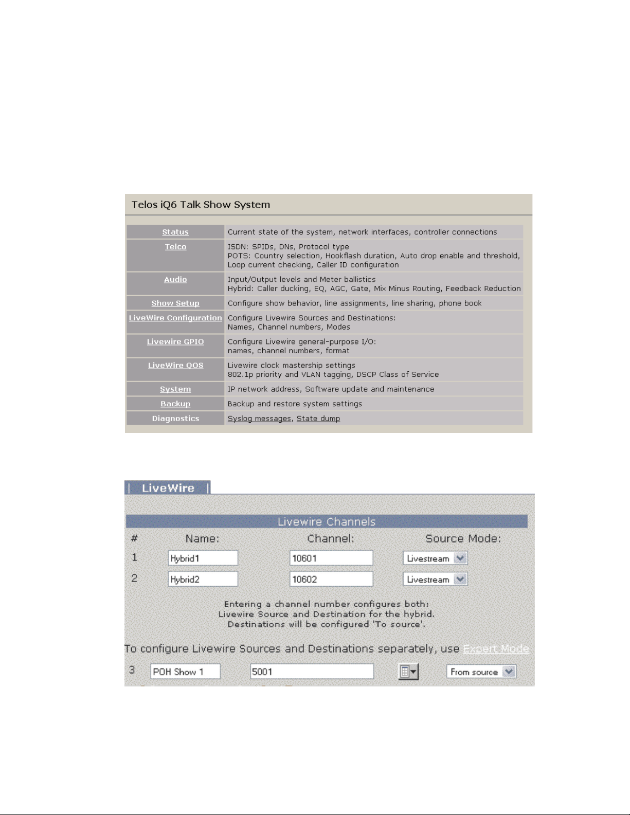
Some basic settings need to be entered into the web interface before you can really do anything with the
iQ6. With a PC that is connected directly to the iQ6 with a cross over cable, or connected through a LAN
and with the correct network settings, open a web browser application and in the address field, type the IP
address which you have assigned to the iQ6.
The Home screen is shown above. First select the Livewire Configuration link. Username is user and the
password should be left blank.
Assign the desired Livewire Channel number in the Channel field so that the iQ6 will produce audio and
send it to the appropriate unique channel. You can also assign the Livewire channel for the Program On
Hold (POH) source, if you have one. Once the correct values are in place, press the Apply button and
continue to the Telco configuration.
From the Telco page, you have the option to configure the POTS or ISDN interface.
Page 18
10 | Section 2
POTS Interface
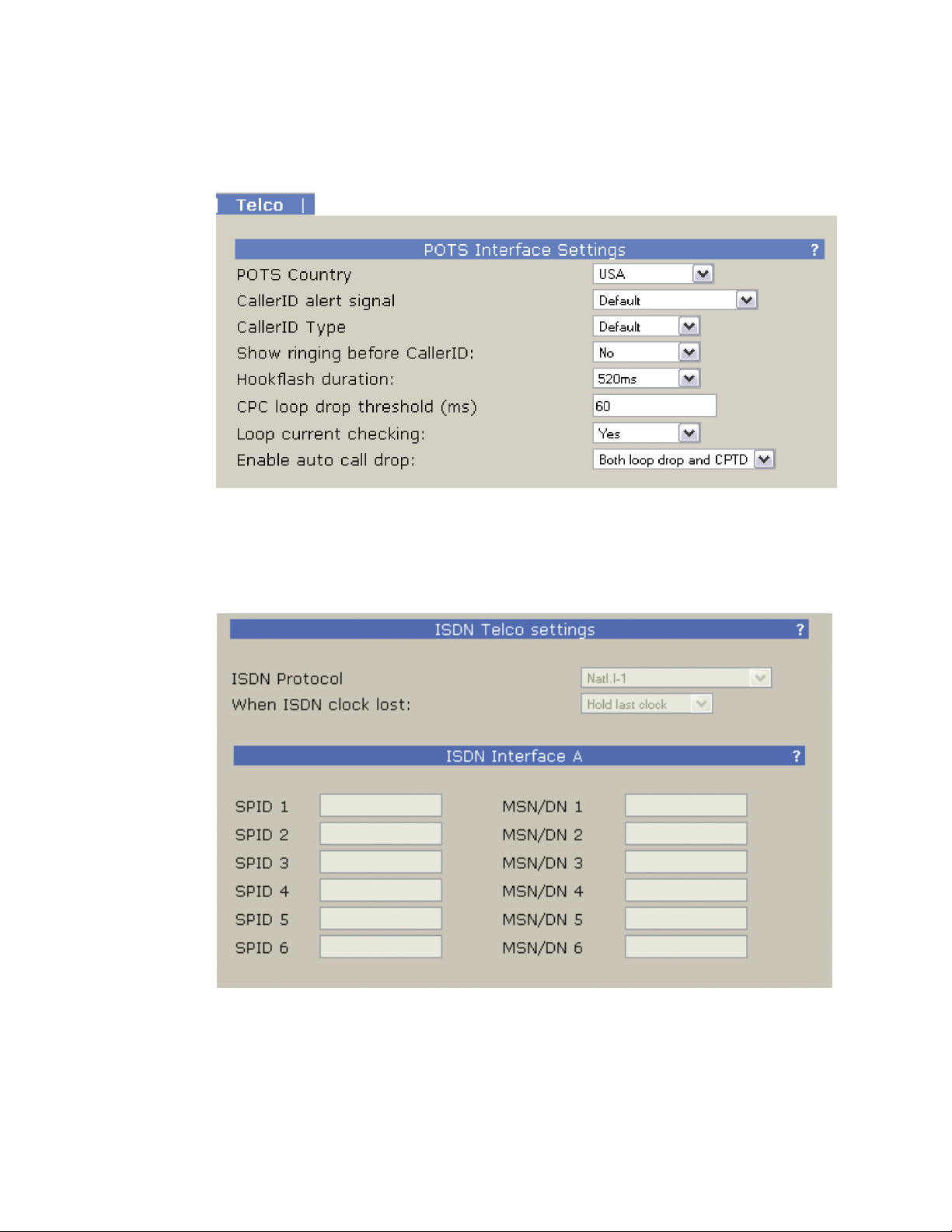
Verify the correct country setting is selected and any of the other desired settings. For reference on the other
settings, refer to the detailed configuration section.
ISDN Interface
Select the required ISDN protocol. For the USA and Canada, this will usually be Natl.I-1. For Europe and
much of the rest of the world, it will be ETS300.
For Natl.I-1, enter the SPIDs for each voice channel given to you by the telephone company. Leave this blank
for other protocols.
Enter the DN (Directory Number) or MSN for each voice channel. The DNs, sometimes called Listed
Directory Numbers or LDNs, are your (usually 7-digit) phone number as listed in the telephone directory.
Page 19

INSTALLATION AND CONFIGURATION | 11
They normally do not include the area code.
In some cases, you may need to enter 10 digits for your DNs.
Click “Apply”, then “Reboot Now” to activate the ISDN circuits.
Successful initialization of a line will be indicated by the idle line state on the front display of the iQ6. This
state is shown with a single dot for each active line in the center row of the front display.
The same indicator is also available on the Status page of the web interface.
4 active lines shown initialized
Tips
Incorrectly entered SPIDs are the most common problem users in the USA & Canada have
when placing ISDN calls. Compare the SPIDs you have entered with the SPIDs provided to
you by the phone company to be certain that you have entered them correctly. Do not add
anything to your SPIDs. Note that there are no hyphens, dashes (-), or spaces in SPIDs so the
system will not allow you to enter any non-numeric characters. If your installer has included
them in the SPID, ignore them.
If you have PTP (AT&T Point-to-Point) or ETS300 (Euro-ISDN) ISDN protocol, you should not
enter anything in the SPID elds.
If you experience problems only with incoming calls, check your DNs.
2.4 Client Conguration
There are three different clients which can connect to the iQ6. The client limit connection is twelve.
♦ Axia iQ surface (2.4.1)
♦ VSet (2.4.2)
♦ VX Producer (2.4.3)
2.4.1 Axia iQ Surface client
For details on the Axia iQ console, please refer to the appropriate documentation for the product. This
section is here to assist with interfacing iQ6 to your iQ console..
Connect to the iQ console’s web interface and select a Show Profile. The Show Profile page has Phone
Connection settings to be filled in.
♦ Phone Server IP: Enter in the user name, password, and IP address of the iQ6 in the following format:
♦ User: [email protected] ([email protected])
♦ Studio Name: Enter “Hybrid 1&2”
♦ Show Name: This is used for TelosVX systems and may be left blank
Page 20

12 | Section 2
Save your Show Profile and reload it using the Profile key on the console. When the show is loaded, the iQ
will log into the iQ6 as a client.
2.4.2 VSet client
For details on the VSet, please refer to the appropriate documentation for the product.
To set up your VSet for use with iQ6, follow these steps:
2.4.3 VX Producer client
For details on the VX Producer, please refer to the appropriate documentation for the product.
If VX Producer is not connected to a server, options will be available at the top page that need to be filled in.
♦ Press the Setup softkey
♦ Select the VX Engine IP soft key
♦ Enter in User, Password, and IP address
♦ The VSet will log into the iQ6 as a client
♦ VX Engine IP: enter the IP address of the iQ6.
♦ Port: defaults to 20518 and should be maintained.
♦ Username: can be left blank
♦ Password: can be left blank
VX Producer will log into the iQ6 as a client and show the active studio. There is only one studio associated
with the iQ6. Select the “Hybrid 1&2” Studio.
VX Producer is now connected to the iQ6
Page 21
| 13
3
User Operation
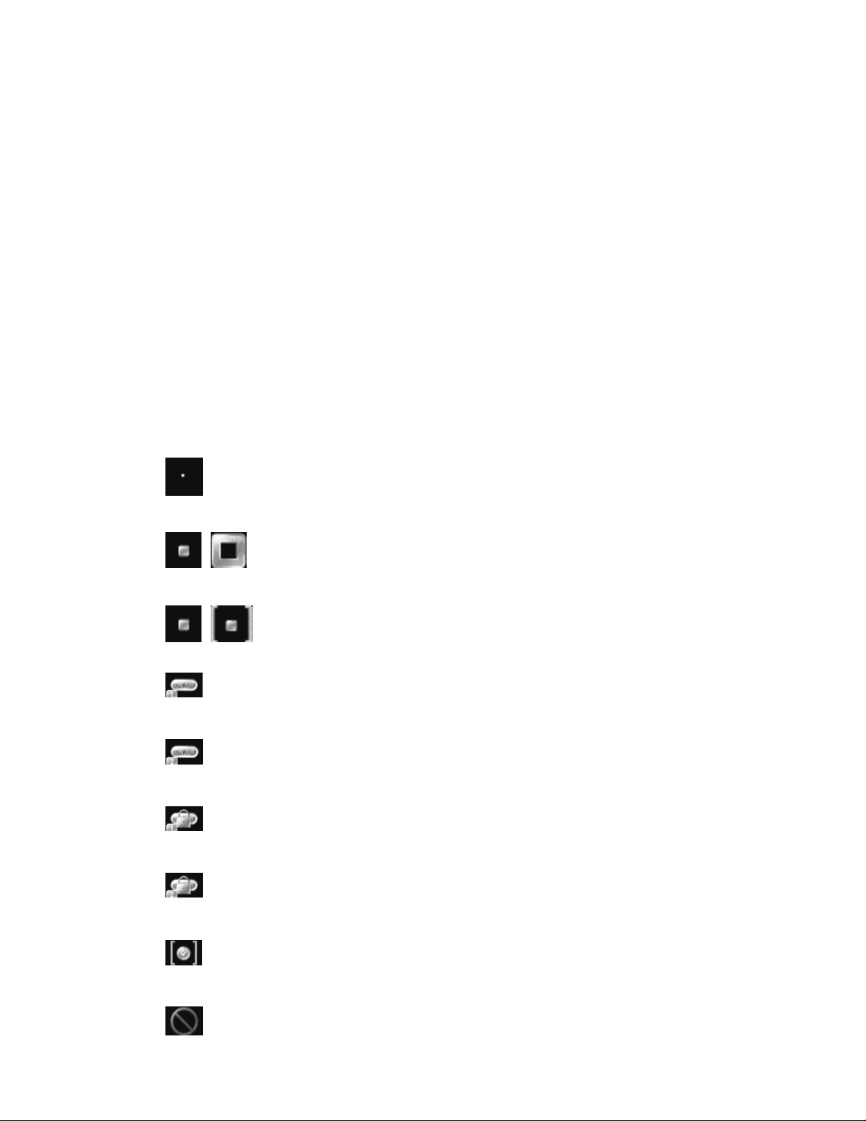
Telco lines used with your iQ6 can be in many different states, simultaneously. The iQ6 has a front panel
OLED display which will show the status of the lines. Also, the web interface on the Status page gives
remote access to these same states. The three different clients, Axia iQ console, VSet, and VX Producer, will
also show the states of these lines. The following symbols define the states.
Line is ready for incoming or outgoing calls
(you may be able to observe a small pulse occur with this symbol)
Line is ringing
Call is on hold
Call is ON AIR – Hybrid 1
Call is ON AIR – Hybrid 2
Call is ON AIR & Locked – Hybrid 1
Call is ON AIR & Locked – Hybrid 2
Screened Hold – Call is on hold and has been screened by Producer
Block All Mode (busy lines)
Page 22

14 | Section 3
Call is in progress (either with VX Producer or VSet)
iQ6 can be controlled by using either the VSet phone, VX Producer software, or the phone controls built
into your iQ console’s Telco frame. Let’s look at each of those controllers.
Axia iQ Console
The Axia iQ console Telco expansion module is designed to interface with the iQ6.
Its basic controls are as follows.
♦ Keypad: Used for placing outbound phone calls
♦ Transfer: Used to create a “hook flash” in POTS analog phone systems. Depending on the way you’ve
ordered your Telco service, this key may serve to activate features such as transfer or 3-Way Calling.
This button does not function with ISDN phone lines.
♦ Block All: Pressing this key once will “busy” all phone lines (except those that are on-air, on hold, or
on a handset), thus blocking incoming calls. Pressing the key a second time will release call blocking.
♦ Line Buttons: Each line has 2 buttons, the left column for Hybrid 1 and the right column for Hybrid
2. Pressing a line button places the caller on that line on-air using the corresponding hybrid. Pressing
a line button when a call is already on-air locks the call on-air, preventing accidental disconnection.
To unlock, press the line button a third time.
VSet
♦ Drop 1 and 2 Buttons: These buttons will drop calls (in their respective column) that are currently
on-air, if that call is not in the “locked” state described above.
♦ Next: Selects the line which has been ringing longest. If no line is ringing, it selects the line that has
been on (normal) hold the longest.
Set Talent or Producer Mode
The VSet should be set to Talent mode when it is located in the studio and is used to put calls on the air.
Producer mode is for a VSet that is being used by a producer to screen calls. In Producer mode, calls cannot
be put on-air and on-air calls cannot be dropped. The function of the right line button column is different in
the two modes to serve the needs of each type of operator, as described below.
Press the menu button to access the menu functions. The LCD will show the various items that can be
changed. Select Talent or Producer and then exit the menu functions by pressing the menu button.
The Line Info Field
Each line has a corresponding portion of the LCD display to the right of the line button that shows status
and info about that line.
Page 23

USER OPERATION | 15
Next indicator
The ‘>>’ symbol. Marks the line that will be taken when the next button is pressed.
Fader number
The yellow/orange rectangle near the status icon.
Line name
The first text line. This is the line name given during configuration.
Caller ID
This is either the incoming or outgoing caller ID, depending upon whether this line is incoming or dialedout. The green arrow to the left of the text points left for incoming or right for outgoing.
Time
The length of time the call has been ringing-in, on hold, on-air and on-handset.
Action ‘hint’
Shows what line will be affected by drop and hold. Choose the line you want to drop or hold after pressing
either of those buttons. This shown only when more than one is possible; this step is not needed when only
one line is possible, when the line would be dropped or held immediately.
Line Button Columns
Each line has 2 associated buttons to the left of the LCD.
Pressing a left column line button puts a held or ringing caller on the handset.
Press the right column button to put a held or ringing line on air, dropping any other unlocked calls. If a
call is already on the air, pressing the right button locks the line, or if already locked, unlocks it. That is, it
toggles between the two states. Not to worry; you cannot drop a call.
In Producer mode you use the Ready Hold button (the one with the checkmark) to put lines in ready hold
mode and assign priority for the Next function. See Next Button and Function. Ready hold works like
normal hold, except the line status icon has the checkmark to indicate to operators that a call has been
determined to be ready for air, normally by a producer/screener.
Hold Button
Holds a call that is ringing, on the handset, or on-air. If more than one line is in this category, there will be a
small hold icon near the status icon on the lines that could be held. Press the line that you want to hold.
Drop button
Drops a call that is ringing, active on the handset, or on-air. If more than one line is in this category, there
will be a small drop icon near the status icon on the lines that could be held. Press the line that you want to drop.
Page 24

16 | Section 3
Lock
Normally, taking a call to air causes any others on-air to be dropped. If you need to conference two or more
calls, you can use the lock function.
Press an already on-air line button to lock it. The line status icon will change to display the locked symbol.
Pressing the button again unlocks the line and the lock icon goes away.
Locked calls remain on air, and cannot be dropped until they are unlocked.
The Drop and Hold buttons have no effect on a locked line.
Next Button and Function
The Talent next priority is:
1. longest waiting ready hold
2. longest waiting hold
3. longest ringing-in
The producer can manually override these and assign priority as desired.
The producer mode next priority is:
1. longest ringing-in
In producer mode, Next does not take any held lines.
Busy All
Pressing this button will cause all inactive and ringing lines to be dropped and blocked from accepting any
calls. Calls on-air, on the handset, on hold and Priority lines will not be affected. The usual application
for this function is to let you prevent early callers from getting in on contests until after you’ve made the
announcement and released the lines to accept calls.
Pressing Block All again will release the lines and allow incoming calls.
Numeric Keypad
For dialing out, either on the handset or on-air. It works during an active call to generate tones for voice mail
and other services.
While a number is being composed, the digits will appear in the line info field. After a number is entered, the
GO button causes the connection to be made, in similar fashion to a mobile phone.
Re-dial Function
After selecting a line, press the GO button before any digits are dialed. The last dialed number appears in the
line info field. Pressing GO again causes dialing to start.
Fader Assign
Normally, when a call is taken, it goes to fader 1, but you can assign it to the second console fader. When a
call is on-air, or before it is taken, the round fader assign buttons to the right of the LCD can be used to move
the call to the desired fader. The number in the yellow rectangle in the line info field shows you which fader
is or will be used.
Page 25

USER OPERATION | 17
Take it Easy
In the simplest case, when you are a talent supported by a producer, you could just use the Next and Drop
buttons. You press the Next button to take calls in the sequence determined by your producer and you press
the Drop button when you are finished with your last call and you want to stop taking more.
One step up would have you pressing the right column line buttons to select the calls you want, one at a
time. Again, when you are finished taking calls, you would press Drop. You could use the left column line
buttons to talk with callers on the handset.
VX Producer
Introduction
The VX Producer application integrates:
♦ Call screening and production communication
♦ Recording, playing, and editing calls
♦ A ‘softphone’ for talking with callers off-air
Normally, it would be used by producers or call screeners to communicate with callers and the on-air talent.
Each would have a copy running on a PC near to them.
Managing Calls
The main window shows a list of the lines that are available.
Near the bottom of the screen is a tabbed list box, controls, and an audio level meter that are used for the
recording and play functions.
At the lower right is a window used for text chatting between the producer and talent.
Handset
Press the handset button to the left of any line to take the call to the ‘handset’ that is connected to the PC
running the VX Producer application. (Often this will actually be a headset/mic.)
If no call is ringing-in, the system assumes you want to dial out and opens a window to let you do that.
On-air
Pressing this button takes a call to the studio mixing console. Your operation of the console determines
whether the call is actually on-air or sent to preview or to somewhere else. Usually the studio mic (or
microphones) are used to talk with a caller, whether on-air or not.
The Line Info Field
♦ Fader number. Before a call is taken to air, this shows which fader it will be assigned to when it is put
on-air. After a call is on-air, this shows which fader is assigned to the call. The number changes when
you move a call using the fader assign buttons.
Page 26

18 | Section 3
Drop, Hold, and Hold Ready Buttons
Drop disconnects a call that is ringing, active on the handset, or on-air. If more than one line is in this
category, they will all be highlighted. Press the line that you want to drop. Or select the line you want to drop
to highlight it and then press Drop.
Hold puts a call that is ringing, active on the handset, or on-air into hold. If more than one line is in this
category, they will all be highlighted. Press the line that you want to hold. Or select the line you want to hold
to highlight it and then press Hold.
Hold Ready puts a call that is ringing, on-air, on the handset, or on hold to the hold ready (screened) state.
♦ Next indicator. Shows which call will be taken when you press the Next button.
♦ Line status icon.
♦ Line name. This is the name that was given to the line during show configuration.
♦ Caller info. Text you enter into this area will appear on any other VX Producer applications and
VSets that are assigned to the same studio. It automatically replaces the line name text.
♦ Telephone number. Shows incoming (caller ID) or outgoing (dialed) number. The small arrow
near the number points left for incoming and right for outgoing numbers.
♦ Time. Shows time that a call has been waiting on hold, on-air, on handset, or ringing.
Lock/Unlock Button and Function
Normally, taking a call to air causes any others on-air to be dropped. If you need to conference two or more
calls, you can use the lock function.
Press an already on-air line button to lock it. The line status icon will change to display the locked symbol.
Pressing the button again unlocks the line and the lock icon goes away.
Locked calls remain on-air until unlocked and then another call is taken to air or the call is explicitly
dropped or held.
The Drop and Hold buttons have no effect on a locked line.
Fader Assign Buttons
Normally, when a call is taken, it goes to “fader 1”, but you can assign it to the other console fader.
Next Button and Function
The Talent next priority is:
1. longest waiting ready hold
2. longest waiting hold
3. longest ringing-in
The producer can manually override these and assign priority as desired.
The producer priority is:
1. longest ringing-in
Page 27

USER OPERATION | 19
Block All
Pressing this button will cause all inactive and ringing lines to be dropped and blocked from accepting any
calls. Calls on-air, on the handset, on hold and the priority lines will not be affected. The usual application
for this function is to let you prevent early callers from getting in on contests until after you’ve made the
announcement.
Pressing Block All again will release the lines and allow incoming calls. The specific lines blocked are
determined by configuration. Normally, VIP and hotlines are configured as priority lines, and therefore
not busied.
Recording, Editing, and Playing Calls
Pressing the Record button starts a recording of the currently active phone call.
In talent mode, this will be the “on-air” call. Usually, the audio will have been routed via the studio mixing
console.
In producer mode, this will be the call on the handset.
You can choose if both the local mic audio and the phone are recorded or only the phone. In the former case,
a stereo file will be produced.
Enabling Auto Record causes the recorder to automatically make a new recording each time a call is taken.
File names are automatically created by the system, but can be changed by writing over the default text
after a right mouse click. The file will appear in the tabbed list box determined by Settings. Normally, a VX
Producer in producer mode will put recorded files under the Producer tab and in studio mode, under the
Studio tab (naturally). You can move files among the tabbed lists by either dragging them to the destination
tab or using the Send button and drop-down list.
The meter to left of the tabbed file list window shows the audio level as a recording is being made.
Playing
Select a file by clicking on it. Press the Play button. The audio will be sent to the PC’s output configured in
Settings. Depending on the Settings configuration, the playback will be available on PC-connected loudspeakers or headphones, or it may be routed to a studio mixing console fader.
Editing
Select a file by clicking on it. Press the Edit button. The audio editor configured in Settings will open and
the selected file will appear in the editing window (Audacity is the default). Audio input and output will be
according to the editor’s configuration. Depending on the configuration, the payback will be available on
PC-connected loudspeakers or headphones, or it may be routed to a studio mixing console fader.
A stereo file will be passed to the editor when both a mic and phone audio are recorded. A mono file will be
passed when phone-only record mode has been selected.
Host/Producer Text Chatting
The window at the lower right lets people within a Studio communicate with each other. Type text into the
lower field and it will appear on any other VX Producer applications connected to your studio.
The ‘Studio’ and ‘Producer’ identifiers are added automatically. The colors for them can be configured in settings.
Page 28

Page 29
| 21
4
Detailed Configuration & Reference
4.1 Front Panel
The iQ6 includes four LED bargraph meters. The ballistic (time) characteristic of these meters changes
depending on the Audio menu Input Level setting. In VU mode, they have the usual 300ms time-constant. In
PPM mode, they have a 10ms attack and 2.8sec release characteristic.
Two meters are labeled input for hybrid 1 and 2.
Two additional meters are labeled for output for hybrid 1 and 2.
There is a single LED labeled POH which shows the presence of Program on Hold audio.
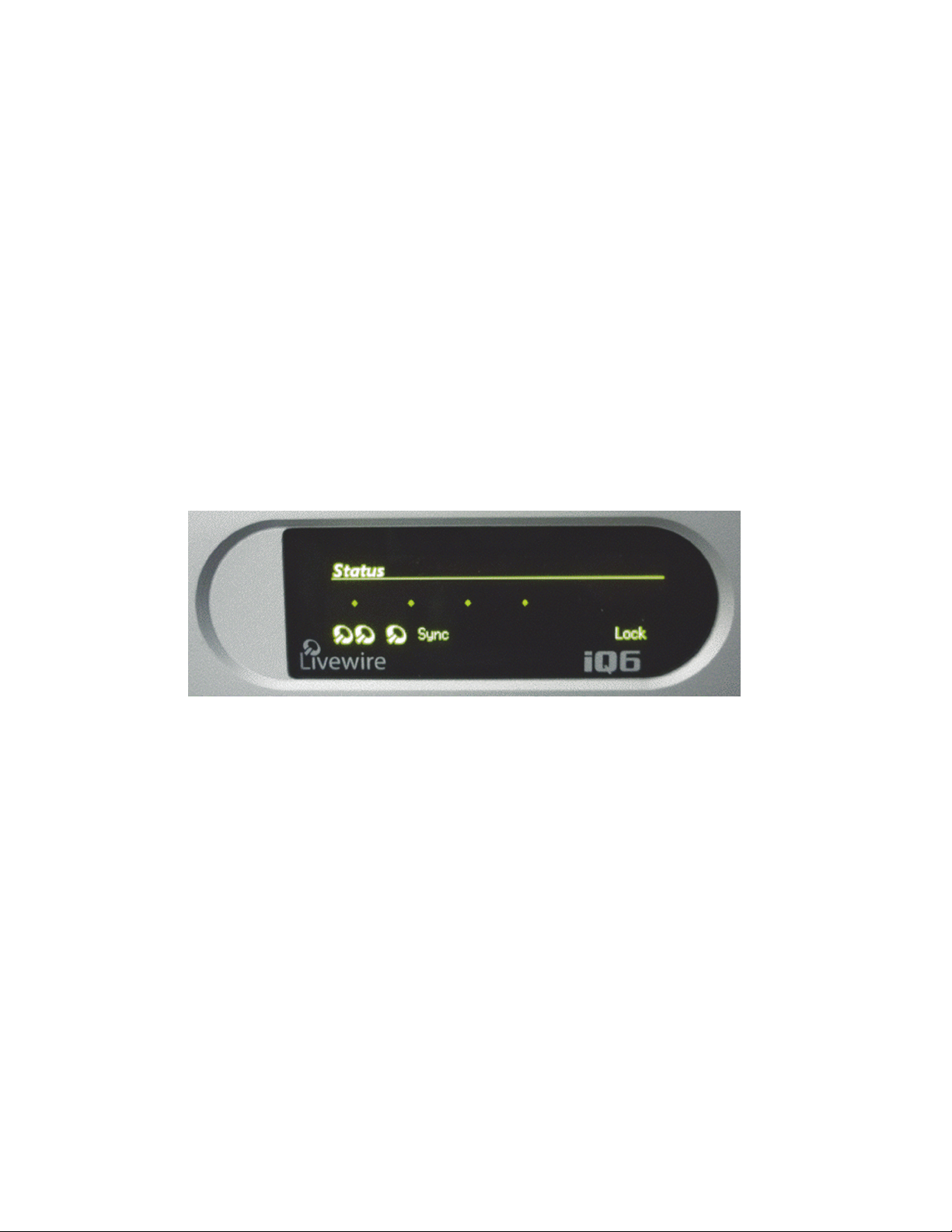
The OLED display of the iQ6 provides status information as well as some basic configuration.
The status screen provides the state of each of the six telco lines (states are indicated by icons described in
chapter 3), input state, digital sync, and lock.
Pressing any of the three buttons will enter into the main configuration screen where the options available are:
♦ Audio (audio settings and adjustments)
♦ Telecom (telco settings and adjustments)
♦ System (base system options)
♦ Status return to default status page
If no activity happens for 2 minutes while on this screen, the display times out back to the Status screen.
Page 30
22 | Section 4
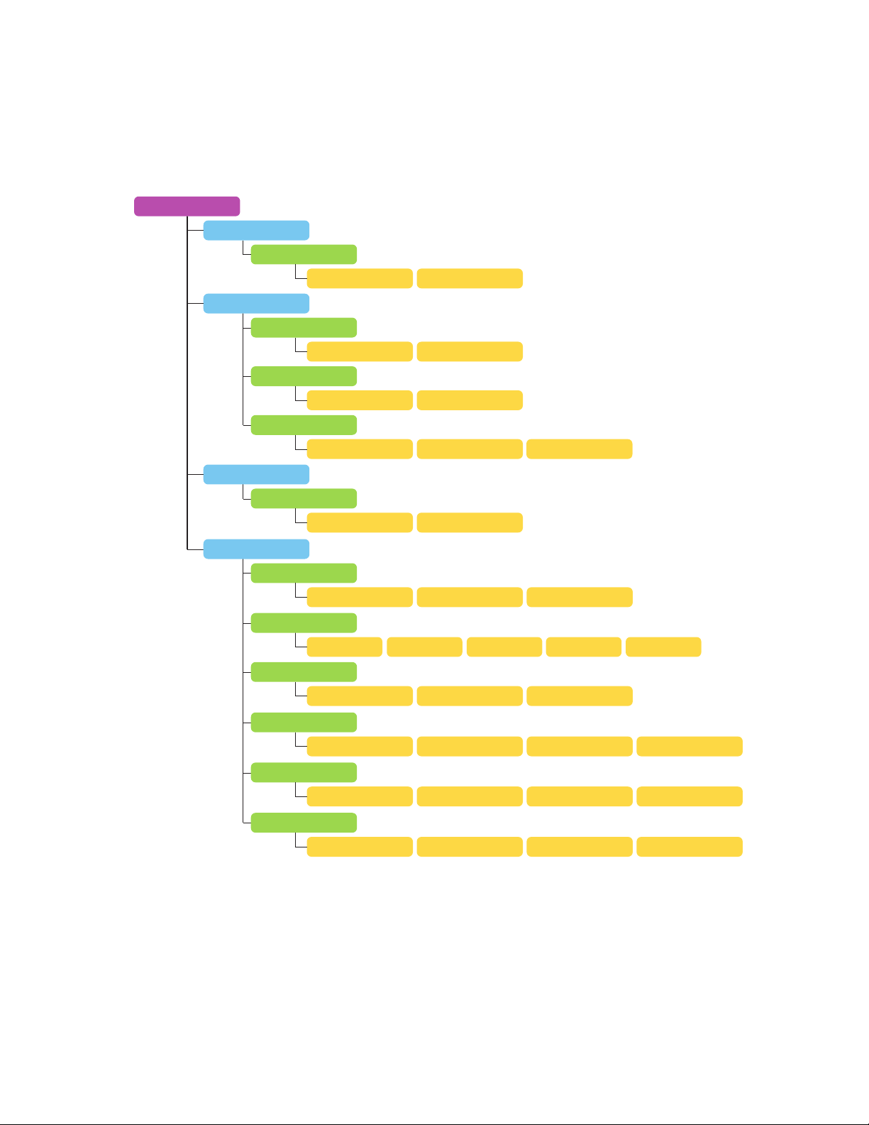
4.1.1 Audio Menu
Audio Menu
Disable Livewire
Studio Audio
Nominal Input
Nominal Output
Meter Mode
To Caller
Phone Send Gain
Confirm
Yes No
VU PPM
VU PPM
Studio 1 & 2 Phone 1 & 2
0dB +2dB
POH
From Caller
Caller Ducking
Receive AGC
Noise Gate
Receive EQ
EQ High
EQ Low
Full -1dB to -15dB
Full
Normal Off
Adaptive Fixed
0dB +2dB
0dB +2dB
3/4 1/2 1/4 Off
Half
Aggressive
Off Adaptive + Fixed
+4dB +6dB
+4dB +6dB
Page 31
DETAILED CONFIGURATION AND REFERENCE | 23
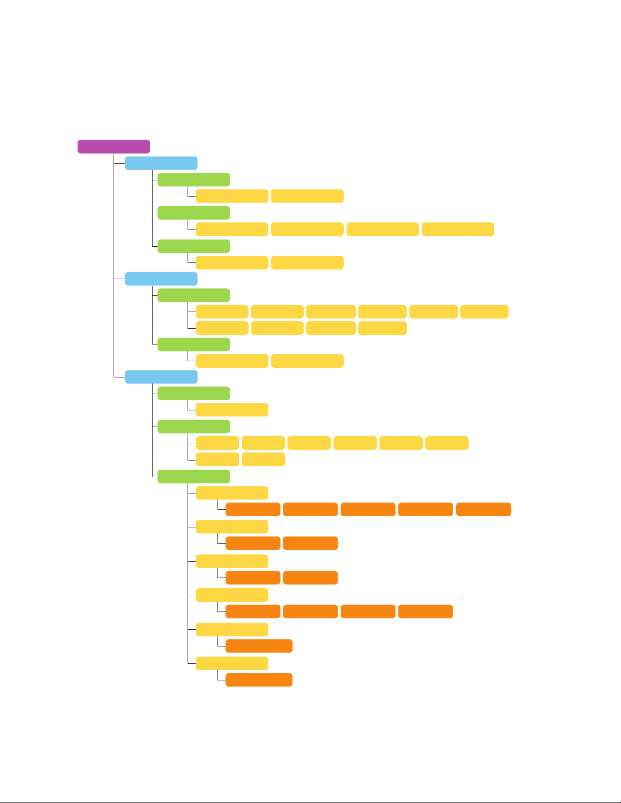
4.1.2 Telco Menu
Telco Menu
Studio Lines
Auto Hold
No Yes
Hold On Select
Producer Both
Lock to Hybrid
ISDN
ISDN Protocol
Clock Loss
POTS
Country
Hookflash
Advanced
None Talent
Off On
Natl. I-1 ETS300 Euro
Auto(US) Q9341/Mu ATT Cust. DMS Cust.
Hold Last Internal
(Too many to list)
720ms
120ms 70ms
CID alert
620ms
Default Ring Line Reversal DT-AS Rev + DT-AS
Ins64 Natl. I-2 VNX AUS
520ms 420ms 270ms 220ms
Ring pre-CID
No Yes
Loop Check
Yes No
Auto Drop
Disable CPTD Only Loop Only Loop+CPTD
CPC Delay
Numerical Value
POTS Sharing
Enter in IP Value
Page 32
24 | Section 4
4.1.3 System Menu
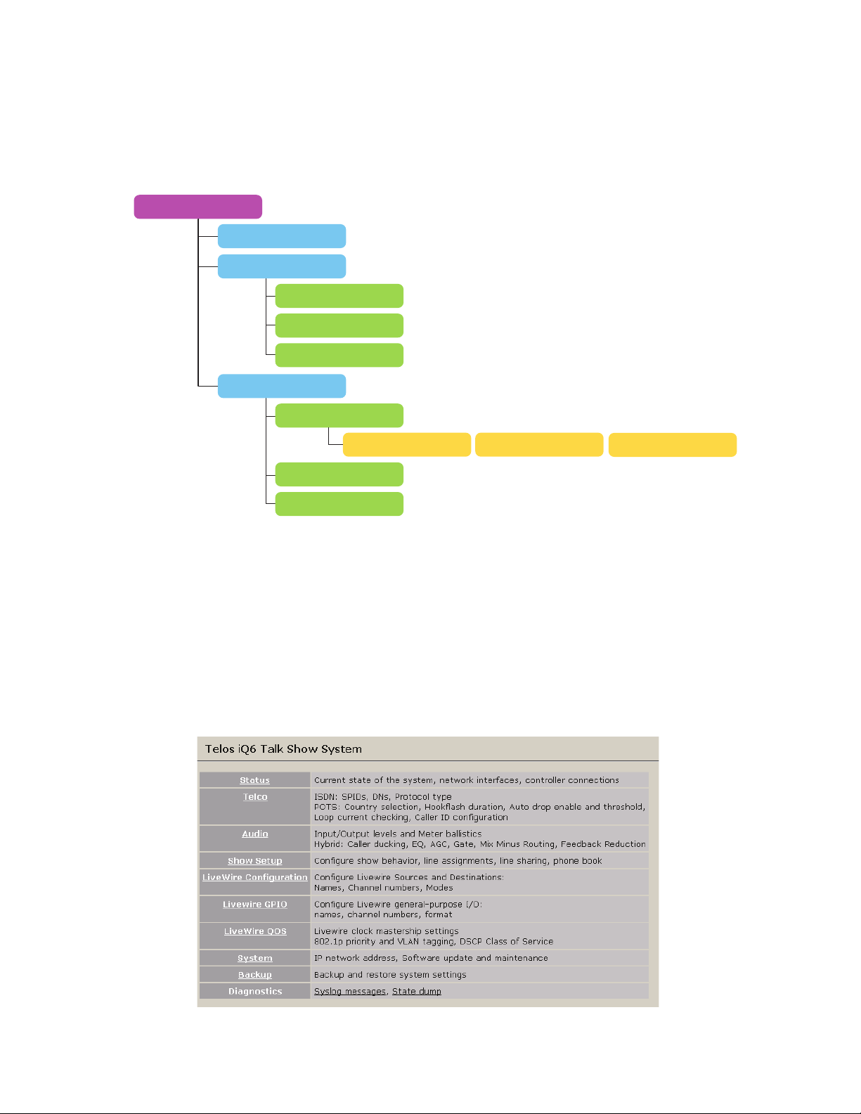
System
Contrast
Networking
IP Address
Subnet Mask
Gateway
Diagnostics
Audio Loop
Reboot
Restore Defaults
4.2 Web User Interface
A web browser can be used to remotely configure and administer the system. All front panel configuration
options are duplicated on the web pages. Certain advanced options such as entering ISDN DNs/SPIDs and
Livewire configuration require the web interface.
You can connect a PC directly to the iQ6 with an Ethernet cross-cable. Or you can connect both the PC and
the iQ6 to an Ethernet switch or the switch in the Axia iQ Core.
After you have a network connection between your PC and the iQ6, open a Web browser and enter the IP
number assigned to the iQ6 into the address entry field. You will then see the iQ6 main Web screen:
Off No EC
Studio
Page 33
DETAILED CONFIGURATION AND REFERENCE | 25
Upon clicking any of the menu links, you will be prompted to enter a user name and password.
The default user name is “user” and the password is <blank> (no password).
The Status, Administration, Telco, Audio, Show Setup, Backup, Miscellaneous, Livewire Configuration,
GPIO, and QoS menus provide access to the full set of configuration options, a superset of those available
on the front panel. The ISDN SPID and DN entries are only available on the web interface. (It’s not very
convenient to enter numeric data on the LCD/ button interface, so we thought you’d appreciate having a
PC’s keyboard for that.)
Some pages have a “?” in the title bars. These are links that open information pages. Some of the features
described in this manual are also described in these help pages. If a new feature is added to the product prior
to a manual update, the help page will provide the details to the new feature.
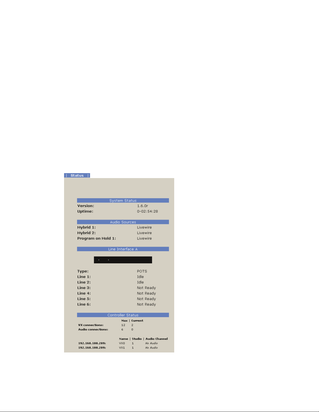
4.2.1 Status
The status page does not provide any configuration options, but it provides useful information as to the
status of your iQ6. Take note of the version of code running on the iQ6, VSet (connection counts), and the
Line Interface states (handy remote access information).
Page 34
26 | Section 4
4.2.2 Telco
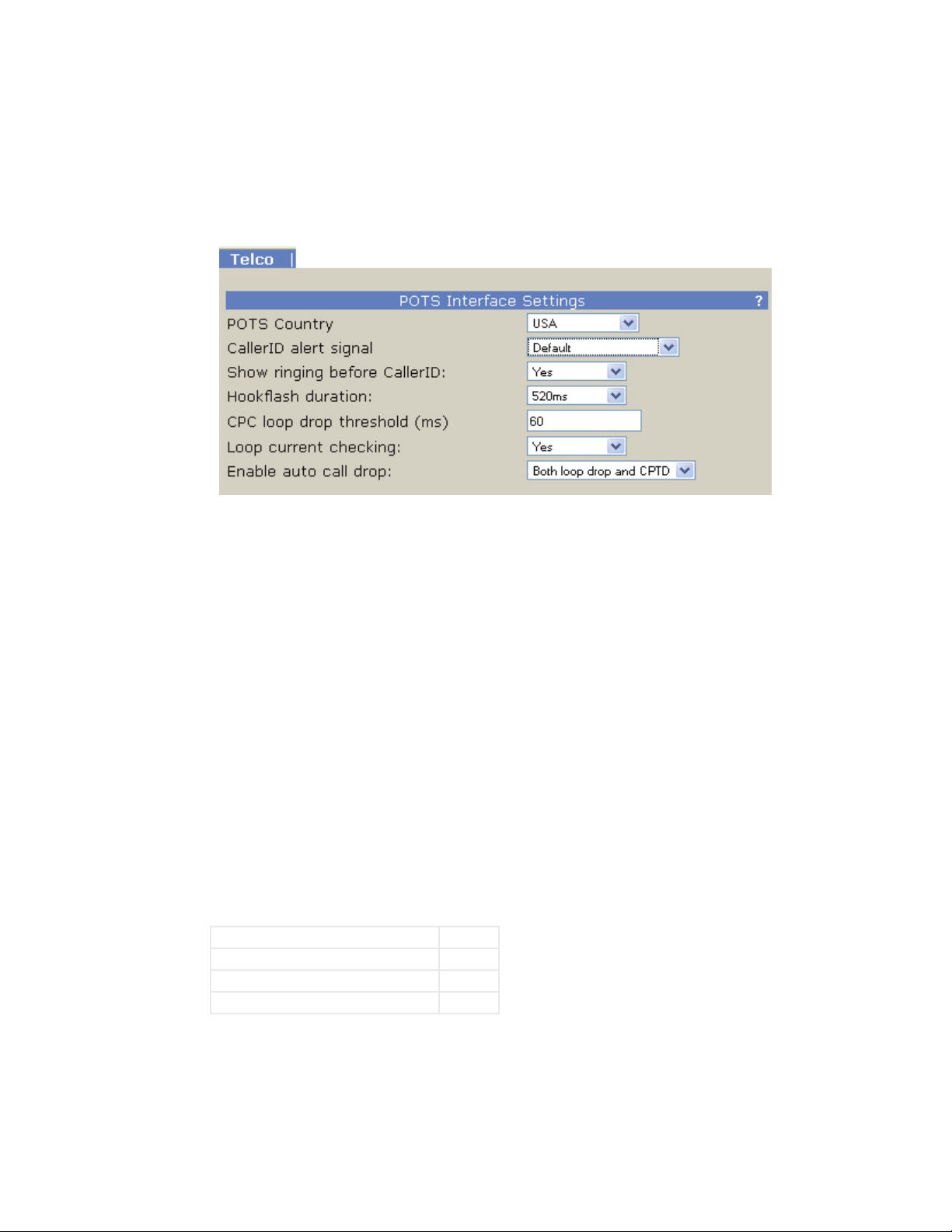
POTS Interface Settings
POTS Country
This setting configures the analog Telco line interface for proper impedance matching and other characteristics for different countries. If your country is not listed, try using: CTR21 (European standard) or USA.
Caller ID alert signal
The behavior of “Default” is determined by the POTS Country setting. If “Default” does not work, ask your
telco what Caller ID alert signal they send.
Show ringing before Caller ID
Normally the ringing indication is passed to the VSet and other devices after the Caller ID has been received.
This delays the ring indication until after the second ring. You may want to have a faster ring indication, and
choosing “Yes” here lets you have it. But you risk losing the CID if an operator answers the call quickly. Some
lines don’t have CID and in this case this should be set to Yes since there is no reason to wait for the second
ring.
Hookash duration
Adjusts the duration of the “hook flash” (loop current interruption) when the Transfer key is pressed. The
default value is 720 milliseconds. The following table indicates typical values for various countries:
USA 720 ms
Belgium, Netherlands, Switzerland 120 ms
France, Luxemburg, Portugal, Germany 270 ms
Rest of Europe 90 ms
The hook flash is sometimes used as a signal to initiate transfer or other features, with the specific effect
being dependent on the Telco or PBX capabilities and configuration.
CPC loop drop threshold (ms)
Sets the threshold time value for loop drop disconnect.
Page 35
DETAILED CONFIGURATION AND REFERENCE | 27
WARNING
If CPC time is set to less than 250 ms, disconnection can occur on polarity reversal/answer
supervision on outgoing calls in some countries.
Loop Current Checking
The iQ6 periodically checks each analog line port for loop current. When current is detected, the single dot
icon appears on status screens and the line is ready. This process is called Loop Check. Yes is the default.
When you are using “ground start” lines, this should be set to No. Note: The iQ6 does not support outbound
dialing on ground start lines. However, setting Loop Check to No will allow incoming calls to work normally.
Note
Ground Start analog lines are not fully supported. Only Incoming calls are allowed.
You can, however, take advantage of this to get a feature that might be useful:
preventing outgoing calls.
Enable Auto Call Drop
Calls can be automatically disconnected when the far end hangs-up. Most USA-style Telco lines provide
a momentary loop drop for this purpose, but non-USA lines and most PBXs provide a tone signal (Call
Progress Tone - Disconnect) instead. The iQ6 can respond to one, both, or neither of these signals. The type
of tone signal detected for CPTD is determined by the POTS Country setting.
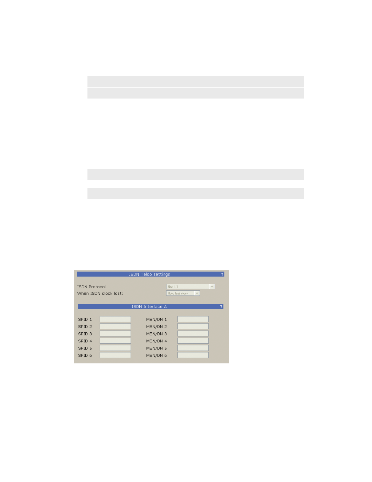
ISDN Interface Settings
ISDN Protocol
Selects the ISDN protocol, which must correspond to the ISDN circuits you are using. It will apply to all
ISDN lines.
There are a number of choices, but the most common are described below.
For Europe and many other parts of the world
- ETS 300. This is the very common Euro-ISDN, according to the ETS 300 standard.
For USA & Canada and a few other parts of the world
Page 36

28 | Section 4
If you are in Europe or most of South America, you should choose ETS 300.
If you have Net64 ISDN in Japan you should select INS64.
If you are in Hong Kong you should choose AT&T Cust.
If you are in the USA or Canada, use whichever protocol your phone company has provided. If you do not
know, you may be able to guess...
Guessing the ISDN Protocol setting in Canada & the USA
- Natl. I-1. National ISDN-1 is the most common protocol for the USA & Canada and some other
parts of the world. May also be used with lines conforming to National ISDN-2. See the notes about
SPIDs, below.
- DMS Cust. For ‘custom functional’ lines on the Nortel DMS-100 switch. See the notes about
SPIDs, below.
- AT&T Cust. This is the AT&T PTP protocol, sometimes called ‘AT&T custom Point-to-Point’. This
protocol generally does not allow two simultaneous voice calls. For this reason we recommend that
the National ISDN-1 protocol be used if you are on the AT&T/Lucent 5ESS Telco switch.
- If you were given only a single phone number and no SPIDs try AT&T Cust
- If you were given 2 SPIDs with the format: 01+7 digit phone #+0 try AT&T Cust
- If you were given 2 SPIDs with the format: 01+7 digit phone #+000 or 01+7 digits +011 try Natl.I-1
- If you were given 2 SPIDs with the format: area code+7 digit phone #+4 digits (for example 0101,
0100, 0111, or 1111) try Natl.I-1. If that fails Try DMS Cust
- If you were given 2 SPIDs with the format: area code+7 digit phone #+1 digit (for example 1, or 0)
try DMS Cust. If this fails try Natl.I-1
- If you were given 2 SPIDs with the format: area code+7digit phone #+2 digits (for example 01, 11,
02, or 00) try DMS Cust. If that fails try Natl.I-1
- If you were given 2 SPIDs with the format: area code+7digit phone #+3 digits (for example
000,001) try Natl.I-1. If that fails try DMS-Cust
- If you were given a single phone number and a single SPID with the format: of 01+7 digit phone#+0
try AT&T Cust (Do not enter this SPID)
- If you were given a single phone number and a single SPID with the format: of 01+7 digit
phone#+00 try Natl.I-1. If that fails try AT&T Cust
- If you were given a single phone number and a single SPID with the format: of area code+7digit
phone#+4digits (for example 0101, 0100, 0111, or 1111) Try Natl.I-1. If that fails try DMS
Note
After you enter (or change) your SPIDs or DNs, you must reboot. Therefore, once you have
entered SPID1, SPID2, DN1, and DN2 you should turn the power o and then back on. Then
go to the Status screen and verify Ready status for both channels.
Clock Loss
This setting is relevant only when there are ISDN lines that “go to sleep” or there is some other unusual
ISDN Telco condition. Most users should leave this set to the default setting of Hold Last.
Page 37

DETAILED CONFIGURATION AND REFERENCE | 29
SPIDs and MSN/DNs
There will be entry locations for SPIDs and MSN/DNs for all line positions, whether needed or not. After
entering the numbers, you must click ”Apply” and then ”Reboot Now” at the bottom of the page to activate
the ISDN lines.
When you are using Natl. I-1 or DMS-100 for your ISDN Protocol mode, you must enter the correct Service
Profile ID (SPID) numbers for each ISDN channel, normally two per physical line. The telephone company
should tell you this number when they confirm your order. Often it is found written on the line jack or
punch block.
Usually the SPID is the area code+phone number+0101. However, we have seen some that include a twodigit prefix and a two-digit suffix, and many other variations are possible. See Appendix 1 for a list of known
working SPIDs. If this works, consider yourself lucky; if it doesn’t work, there is no substitute for getting the
correct SPID from your Telco!
ETS 300 users should disregard all references to SPIDs. Euro ISDN does not have SPIDs.
Notes on SPIDs
1. Incorrectly entered SPIDs are the most common problem USA users have placing ISDN calls.
Compare the SPIDs you have entered with the SPIDs provided to you by the phone company to be
certain that you have entered them correctly. Do not add anything to your SPIDs.
2. Note that there are no hyphens, dashes (-), or spaces in SPIDs, so the system will not allow you to
enter any non-numeric characters. If your installer has included them in the SPID, ignore them.
3. If you have any questions about your SPIDs, call your phone company.
4. If you have AT&T Point-to-Point or ETS300 Euro-ISDN Protocol mode, you should not enter
anything in the SPID fields.
MSN – Multiple Subscriber Number
This item, if required, must be configured from the web interface. Used only when you are using the ETS
300 Euro-ISDN Telco mode and another ISDN device is sharing the line with the iQ6. MSN1 corresponds
to the first B channel. This is simply one of your assigned telephone numbers. Normally, for ETS 300 these
should be left blank.
DN – Directory Number
This item, if required, must be configured from the Web interface. When you are using an ISDN protocol
other than ETS 300 or AT&T Cust. PTP, you must enter the ‘Directory Number’ (DN) here. This is simply
the telephone number associated with the channel.
Tip
Each directory number will correspond to one SPID. You must enter them to reect this
relationship. The DN corresponding to SPID1 must be entered as DN1 while the DN corresponding to SPID2 must be entered as DN2.
If you experience problems only with incoming calls check your DNs. Normally 7 digits
should be entered, but you might need to enter 10 digits.
Page 38
30 | Section 4
4.2.3 Audio
In some cases, lines in a hunt group will require that the same (primary Listed Directory
Number) be entered for all lines that are part of the hunt group.
Some versions of the Telos Zephyr and Zephyr Express do not require that Directory
Numbers be entered. This is not true for the Telos iQ6 and other newer products. You must
correctly enter these numbers for the system to work.
IMPORTANT
After you enter (or change) your SPIDs or DN’s you must restart the system to use the new
information. Therefore, once you have entered SPIDs, DNs, or MSNs cycle power o and then
back on. Then go to the ISDN status screen and verify “Ready” status for all channels.
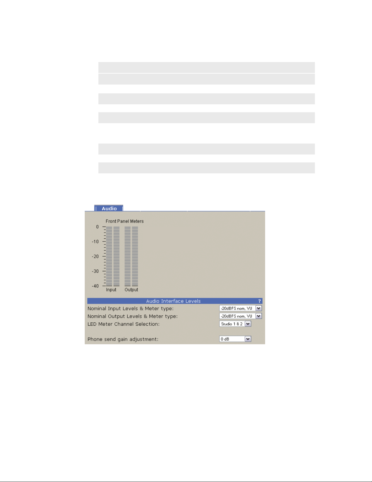
Nominal Input Level and Meter type
Adjusts to the level expected from the Axia iQ console. It is applied before the send AGC.
Increasing the input level past the correct value will not make the send louder due to the AGC/limiter.
The ballistic (time) characteristic of iQ6 meters changes depending on the Input Level setting. When
-20dBFS is selected, the meter has a VU-standard integration time. When +9dBu PPM is selected, the meter
has a PPM time characteristic.
The usual setting is -20dBFS. The +9dBu PPM setting is intended for Euro installations.
Nominal Output Level and meter type
This adjusts the level for the output.
Page 39

DETAILED CONFIGURATION AND REFERENCE | 31
LED Meter Channel Selection
Selects the audio that will be indicated on the LED meters.
♦ Studio 1&2 (default) – Livewire Input and output
♦ Phone 1&2 – Send and receive to/from hybrids 1 & 2
♦ POH in – The Program on Hold input
Phone Send Gain Adjustment
This setting adjusts the level of the hybrid into the telephone line, after the send limiter, and is calibrated
with 0dB representing the usual send level into the line.
The default is 0dB, which should be OK for most telephone lines. If callers consistently complain about low
audio level and you have verified that this is a problem, you can increase the send level. However, doing so
can reduce effective hybrid performance and increase leakage. Conversely, lowering this setting can reduce
leakage.
Call Ducking Level
This control adjusts the amount of ducking that occurs to the received telephone audio when send-to-caller
audio is present. A value of Full Duplex means that the telephone audio is never ducked or attenuated, while
Half Duplex applies maximum attenuation when send audio is present. Intermediate settings range from -1
to -15dB. Ducking is desirable for a variety of reasons:
♦ Allows the announcer to override the caller by causing the received caller audio to be attenuated
(ducked) when the announcer speaks. This is often desired for aesthetic effect and allows the
announcer to remain in control of the conversation.
♦ Dynamically improves effective trans-hybrid loss to reduce leakage, when necessary.
There is also a ducking of the announcer audio to the caller. This is only a few dB unless Feedback Reduction
is enabled, as described below. This send ducker has a fixed value.
Receive AGC
The receive Automatic Gain Control serves to improve level consistency of caller audio. Nominal levels of
the telephone network vary as much as 30dB from call to call. In the past decade our experience has been
that loud calls have become just as much a problem as low level callers.
Therefore we have changed the AGC to act as a platform leveler. The iQ6 uses a dB-linear approach to AGC
with a feed-forward topology, which provides a consistent sound regardless of the drive level. This “smart
compressor” normalizes levels while retaining the natural dynamics of the caller’s voice.
This selection controls the “aggressiveness” of the AGC process, taking values from OFF, 1/4, 1/2, 3/4 to
FULL. We suggest you start with the default value, FULL.
Aggressive AGC is more noticeable, but is also more effective at maintaining consistent levels. Adjustment
of this setting simultaneously changes a number of parameters within the AGC function, such as attack &
release times, thresholds, and compression ratio.
An important feature of the iQ6’s AGC is that it is cross-coupled to other sections of the hybrid so that it can
reliably distinguish between the real caller audio and residual hybrid leakage. This allows a lot of gain on
low level callers while preserving excellent hybrid performance.
Page 40

32 | Section 4
Noise Gate
Enables or disables a noise gate applied to the caller audio. This is a “downward expander” that has the
effect of reducing the noise on the caller audio when it falls below a threshold. On some very low-level calls,
this attenuation may be inappropriate because you may be able to hear the caller fade away when the level
falls below the threshold. It has three settings as follows:
Receive EQ (Caller Dynamic Digital EQ – DDEQ)
Telephone audio frequency response varies widely since many factors can affect it (we’ve measured the
response on a number of calls and the results were revealing). Consequently, some form of receive equalization is desirable. There are three choices for the type of equalization applied to the received telephone audio:
♦ Off – Disables the noise gate
♦ Normal – A slow setting, with moderate noise attenuation
♦ Aggressive – A faster setting with deeper attenuation, for lines where noise is noticeable during
normal conversation.
♦ Off – The caller audio is passed through without modification. The Rcv EQ values are
ignored in this mode.
♦ Fixed – This is a simple manual equalizer mode where a fixed EQ is applied.
♦ Adaptive – This is a three band dynamic equalizer. We’ve chosen frequency breakpoints, time
constants, and other characteristics to optimize the tonal quality of varied telephone callers. The
Digital Dynamic EQ system customizes the callers’ spectral characteristics, which are maintained
from call to call.
♦ Adaptive + Fixed – This mode separately adds a fixed amount of additional gain to the high and low
frequency bands of the three band Digital Dynamic Equalizer.
(Additional) Low EQ
Amount of low frequency boost or cut applied to the caller audio. Settings are in 2dB steps from 0dB to +6dB
are possible with 0dB representing flat response. The default value is +4dB, which sounds good across a
variety of callers, lines, and telephone sets.
(Additional) High EQ High
Amount of high frequency boost or cut applied to the caller audio. Settings from 0dB to +6dB are possible
with 0dB representing flat response. The default value is 0dB.
Diagnostic Test Mode
Should always remain at “Off” unless instructed to be changed by Telos support.
Page 41
DETAILED CONFIGURATION AND REFERENCE | 33
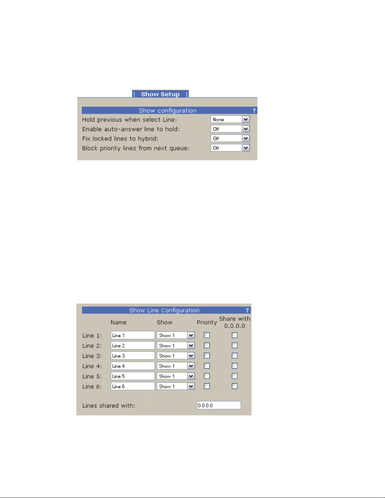
4.2.4 Show Setup
Hold previous when select Line
If a call is in progress (line selected) and another line begins to ring, selecting the second line can either end
the previous call or place the previous call on hold. The option allows you to configure the hold function for
clients that are set as Producer, Talent, or both.
Enable auto-answer line to hold
Enables the auto answer feature. Non-priority ringing lines are automatically answered and put on hold.
Fix locked lines to hybrid
When enabled, you will not be able to transfer a line that is locked on air to another hybrid. If not enabled,
even if a line is locked, the line can be switched to the other hybrid.
Block priority lines from next queue
When turned on, priority lines will not be selected when ‘next’ button is pressed. As a side effect, ringing
priority lines will not trigger the ‘RingOutNorm’ GPIO bit
Line Sharing
Line states can be shared with another iQ6 to enable studio “hot line” sharing between studios. This is
generally a special DID number that only “the engineer” or GM or other would use. If using POTS, you can
plug this line into two iQ6 units and configure this option so that both units know when the line is in use by
the other studio. Both iQ6 units require the opposing unit’s IP address to be assigned in the IP field.
Page 42
34 | Section 4
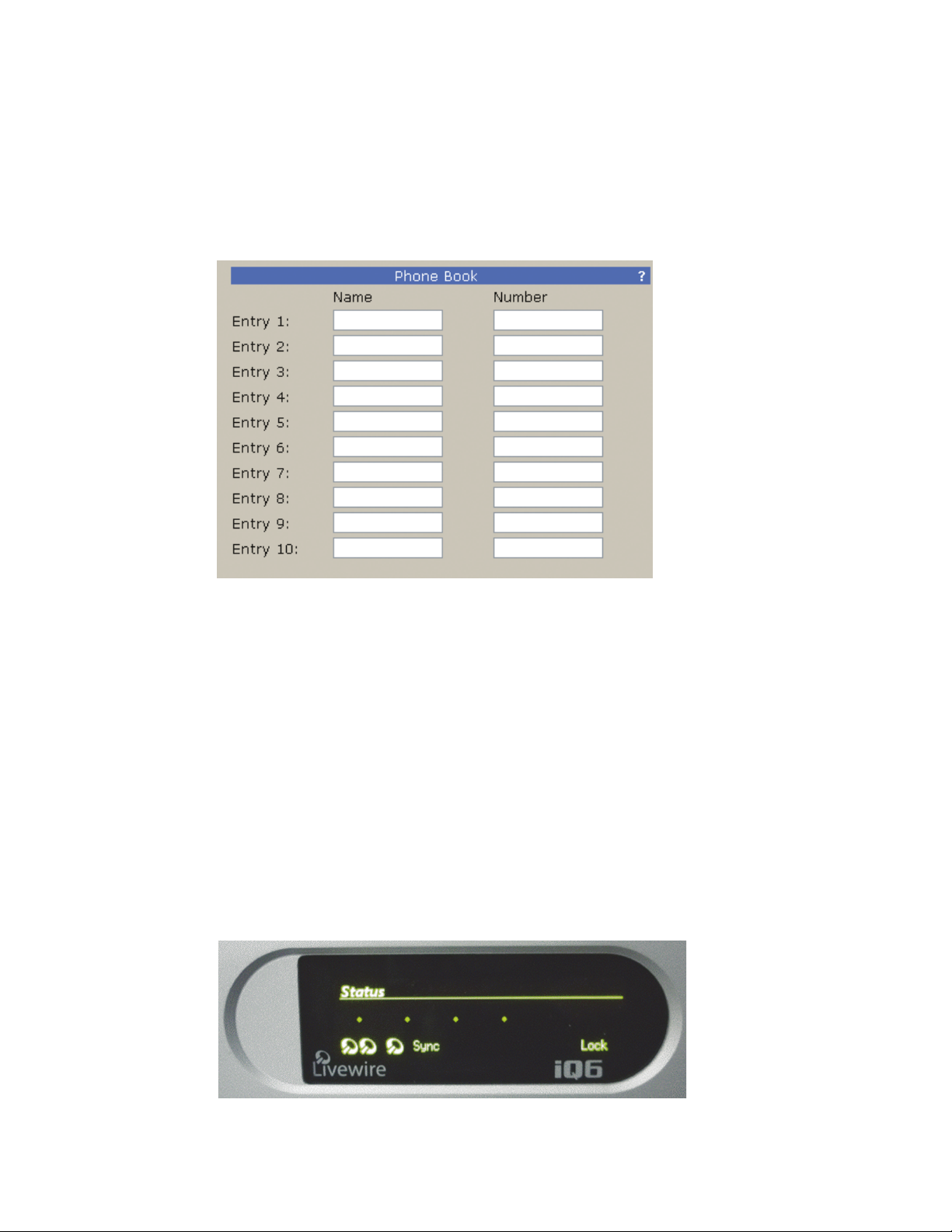
To enable this functionality, enter the IP address of the “other” iQ6 and select which line(s) are to be
shared.
You may also, select which lines are Priority lines. Priority lines are used for studio hotlines and will not be
blocked by the Busy All function.
The bottom of the Show Setup has a new feature set that is introduced with the VX series of products. A
phone book of ten numbers can be added and each entry can be given a name. These values are used
in the VSet phones.
4.2.5 Livewire Audio
The Livewire page has configuration options for the two hybrids and the single Program on Hold (POH)
input. The two Hybrids require unique channel numbers to be assigned. The number can be anything from 1
to 32767, and is unique to your Livewire network.
The Mode drop down box currently has only one choice - Livestream. No configuration is needed here.
The Livewire Destination is configured for you. If there is a need to configure the Destination portion of the
iQ6, select the “Expert Mode” link.
For the POH input, a typical input would be Program 1 from the Axia iQ console.
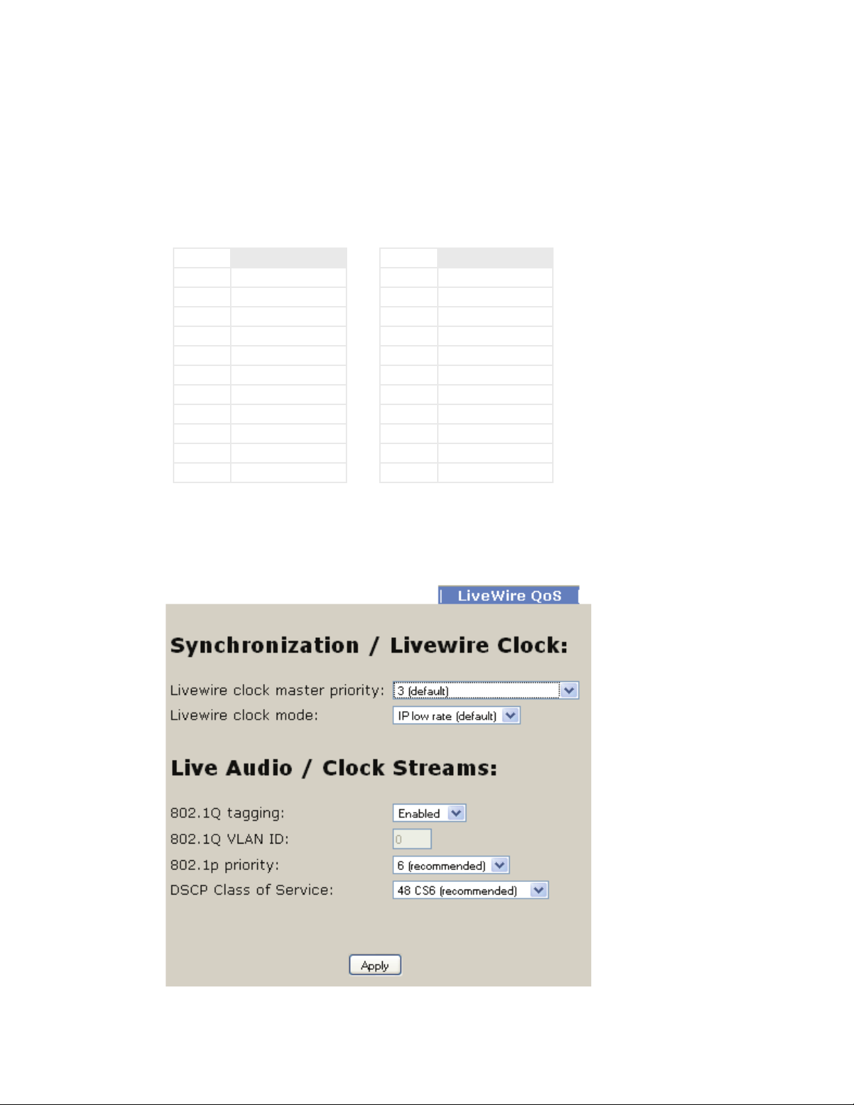
The front display of the iQ6 will indicate if each Livewire input is active. The bottom left of the display will
show the Livewire icon when a stream is valid or a circle if the requested stream is not valid. There are three
indicators. The first is Hybrid 1 input, followed by Hybrid 2 input, and last the POH input.
Page 43
DETAILED CONFIGURATION AND REFERENCE | 35
4.2.6 Livewire GPIO
The iQ6 has two virtual GPIO ports. The logic associated with Port 1 follows the logic defi ned in the fi rst
table, Port 2 is defi ned in the second table:
PORT 1
PIN DESCRIPTION
GPI-1
GPI-2
GPI-3
GPI-4
GPI-5
GPO-1 User Out (Dump)
GPO-2 Ringing Out
GPO-3 Priority Ringing Out
GPO-4 Record Start
GPO-5 Record Stop 1
The GPIO “channel” fi elds should not be assigned the same Livewire channel numbers that are used to
carry the audio streams.
PORT 2
PIN DESCRIPTION
GPI-1 Ring Mute trigger
GPI-2
GPI-3
GPI-4
GPI-5
GPO-1
GPO-2
GPO-3
GPO-4
GPO-5
4.2.7 Livewire QoS
The default settings in the Livewire QoS page should be acceptable for the majority of all installations. We recommend changing these settings only when specifi cally instructed to do so by an Axia Technical Support guru.
Page 44
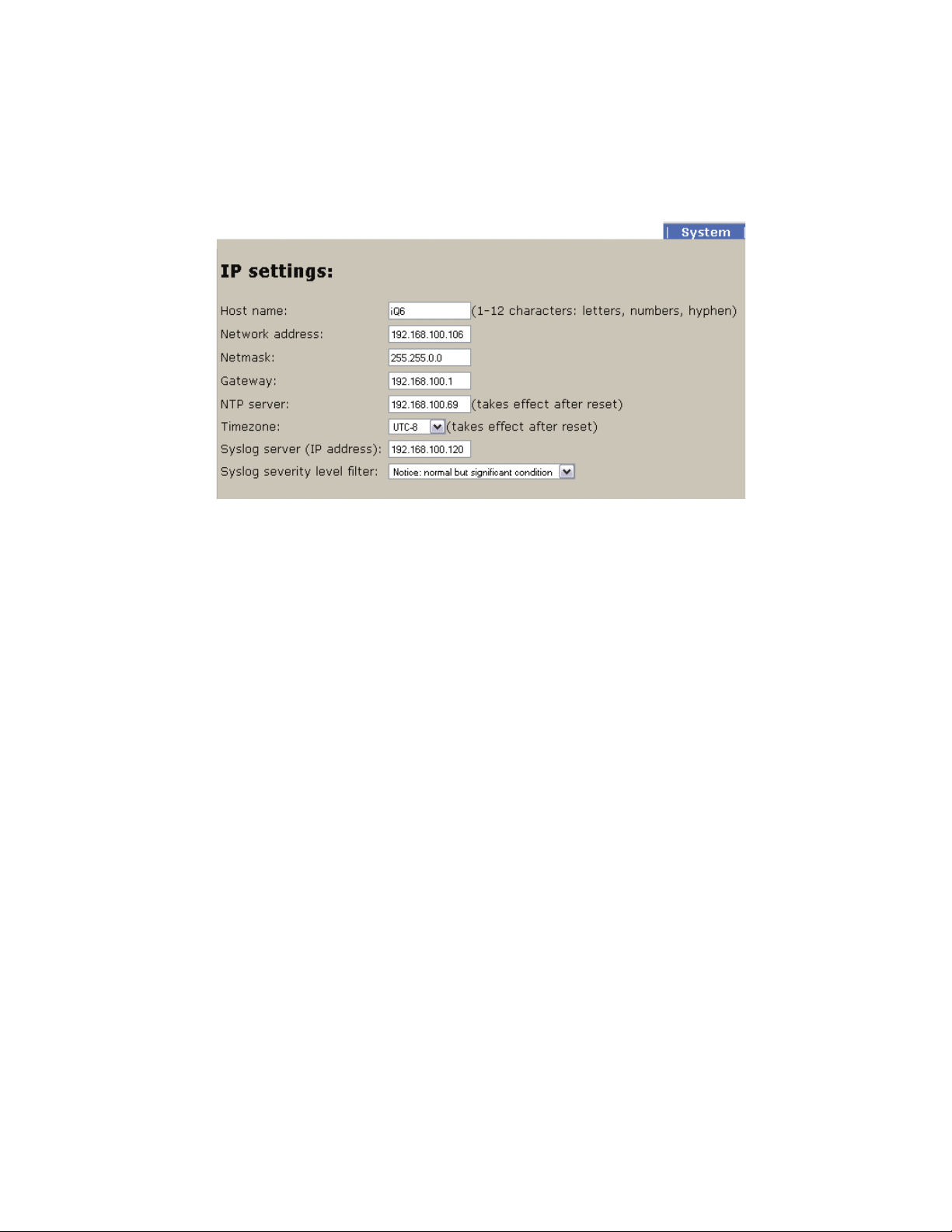
36 | Section 4
4.2.8 System
This menu consists of items that affect basic system operation.
IP Settings
This screen allows you to set various options pertaining to the network settings of your iQ6.
Host Name
The Host Name is a text string you can use to easily identify your iQ6 to browsers and other devices on your
Livewire network. 10 characters is the maximum field size.
IP Address
This set of four three-digit numbers specifies the unique network address of your iQ. During setup, you used
the front-panel controls to enter this address, but it may be changed here as well. This is a numeric-only
field, and each 3-digit sequence (“octet”, in IT terms) accepts numbers from 0 to 255. Do not enter leading
zeros in any of the four fields; for example, if your iQ6’s IP address is to be 192.168.000.012, simply enter
192.168.0.12. Your iQ6 should have an IP address in the same range as the rest of your network (the first
three sets of the numbers should match those of the rest of your network), and the last 3-digit set should be
a number not used by any other network device.
Subnet
The Subnet mask allows you to administer the size of your local network more easily, in smaller chunks.
All devices you wish to communicate with each other should have the same subnet mask values. Packets
addressed to a destination with a different subnet mask are sent to your gateway router, and not to local
devices. Like the IP address, the The subnet mask is a series of four numbers separated by periods. This is
also accessible from the front panel interface.
Gateway
This is the IP address of a gateway router connecting your LAN to another LAN or wider WAN. You will
need to get this value from your network administrator. Leave it blank if you don’t plan on routing audio to
any other networks.
Page 45
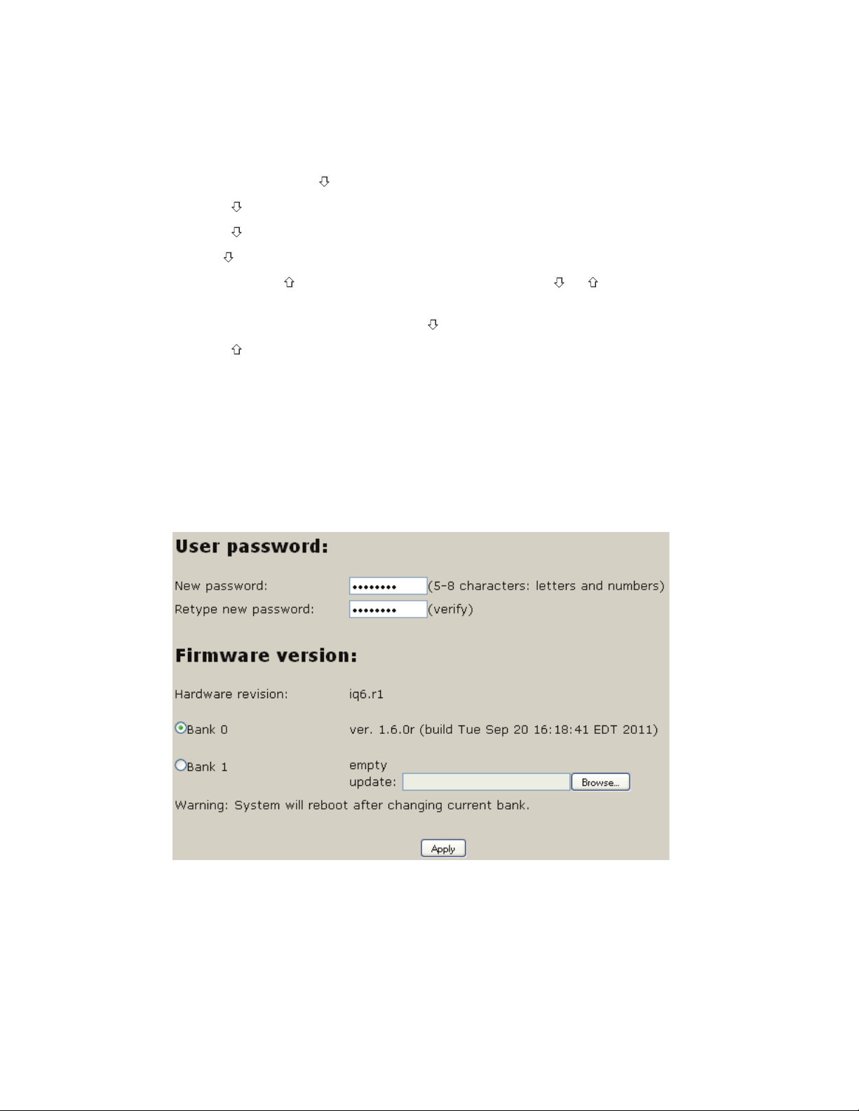
DETAILED CONFIGURATION AND REFERENCE | 37
To enter IP addresses using the front panel interface:
1. Press down arrow key
2. Press to highlight Networking, press (OK)
3. Press to highlight IP address, press (OK)
4. Use to delete and move the curser back.
5. Once you press , you begin to enter a value at curser position. Use and to select the desired
value. Press OK to accept digit.
to highlight System, press (OK)
To delete the previous incorrect digit press
6. Press until the desired digit is displayed.
7. Once all characters are entered, press OK twice to save your entry
.
NTP server
The iQ6 will provide call history to VSet units with date and time. The time stamp will not be correct
unless the iQ6 is able to synchronize to an NTP server.
Syslog Server & Syslog Filter
Permit logging to an external computer running a Syslog server for troubleshooting purposes.
User Password
By default, the web interface has no password. To access the pages, the username is user and the password
fi eld is left blank. If you desire that there be a password to access the web interface, you will enter the
password here.
If you change the password and forget that password, you will need to use the front panel to restore factory
defaults: (Note this clears everything!!)
Page 46

38 | Section 4
System -> Diagnostics -> Restore Defaults -> Restore Defaults -> Yes
The unit will reboot and all settings that have been applied will be lost. You will need to apply the IP address
and restore all settings
Firmware version
The iQ6 has two banks for firmware. To upload a new version, you will have the desired version saved to a
computer, select the Browse button, select the appropriate file. Once the file path is in the text field, press the
Apply button to begin the upload process.
Once a version is loaded to Bank 1, you can use the radio buttons to select which bank you wish to run from.
In order to activate the chosen version, you must press the Apply button. This requires a reboot of the iQ6.
4.2.9 Backup
The backup page provides the option to store the Telco, Hybrid Audio, and Show setup configuration
information to a PC as well as upload a configuration file to the iQ6. Livewire settings are not stored in this
file as of version 1.5.9b.
Page 47

| 39
5
Technical Data & Troubleshooting
5.1 Overview
A consequence of modern surface-mount construction is that it is frequently no longer possible for localrepairs to be made. Special and expensive equipment is required to change parts. As well, today’s equipment is
very complicated and requires repair technicians to have detailed experience and training, and have access
to high-end test equipment.
At the same time, the advent of overnight delivery services means that equipment can be returned to the
factory for quick turn-around repair. Therefore, we do not expect you to fix this unit at the component level,
and we do not include schematics of the unit in the manual. Upon request, our support staff can fax or mail
you the needed schematic. Please see the first pages of this manual for proper procedures on returning units
for repair.
There is the possibility, however, that you could repair the unit by swapping subsystems such as plug-in
modules or power supplies. The Telos customer support crew is standing-by to assist with this, if you need it.
5.2 System Software & Firmware
Viewing Version Information
To assist with troubleshooting, Telos customer support may ask you to provide some software version
numbers. There are two major software components to the system:
♦ System software – This is the software that can be updated by downloading new software.
♦ Firmware – This code is analogous to a bootstrap loader and contains certain critical low level
software. This information can only be updated or changed at the factory. It is stored in a partition of
the non-volatile memory on the motherboard.
The software version and software build date can be determined from the start-up screen. The software
version and software build date are shown.
5.3 General Troubleshooting
Thinking about Problem Solving
Despite best intentions, something could always go wrong. Sometimes troubleshooting a balky set-up can
make even the toughest engineer a Maalox and Rogaine addict.
You can’t fix any system without the right world view; a zeitgeist of suspicion tempered by trust in the laws
of physics, curiosity dulled only by the determination to stay focused on a single problem, and a zealot’s
regard for the scientific method. Perhaps these are characteristics of all who successfully pursue the truth.
In a world where we are surrounded by complexity, where we deal daily with equipment and systems
only half-understood, it seems wise to follow understanding by an iterative loop of focus, hypothesis, and
experiment.
The notions here apply whether you are solving problems at the system level or at the component level. At
Page 48

40 | Section 5
the system level, the actions you might take would be very different – checking cables, trying different menu
settings – but the thinking is the same.
Too many times, we fall in love with our suppositions. We are quick to overtly or subconsciously assume the
problem being chased is due to lousy design, the stupid phone company, or the manager’s latest memo.
Armed with a healthy skeptical attitude, the basic philosophy of troubleshooting any system is to follow
these steps:
Let us now cover each step of the troubleshooting sequence in detail.
1. Observe the behavior to find the apparent bug. In other words, determine the bug’s symptoms.
♦ Observe the behavior to find the apparent problem;
♦ Observe collateral behavior to gain as much information as possible about the problem;
♦ Round up the usual suspects;
♦ Generate a hypothesis;
♦ Generate an experiment to test the hypothesis;
♦ Fix the problem;
♦ Then, repeat, if necessary, to attack additional problems.
Remember always that many problems are subtle and exhibit themselves via a confusing set of
symptoms.
2. Observe collateral behavior to gain as much information as possible about the problem.
Does the LCD’s problem correlate to an LED flashing? Try to avoid studying a problem in isolation,
but at the same time be wary of trying to fix too many at the same time. No one is smart enough
to deal with multiple problems all at once – unless they are all manifestations of something more
fundamental.
3. Round up the usual suspects. At the system level, always suspect the menu set-up, the cables, the
Phone Company line setup, the punch-blocks, etc. At the component level, many computer problems stem from the same sources. Never, never, never forget to check Vcc!
4. Generate a hypothesis. Before changing things, formulate a hypothesis about the cause of the
problem. You probably don’t have the information to do this without gathering more data.
Sometimes you will have no clue what the problem might be. Sometimes, when the pangs of desperation set in, it’s worthwhile to try anything practically at random. You might find a bad plug, an
unconnected line, or something unexpected. Look around, but be always on the prowl for a working
hypothesis.
5. Generate an experiment to test the hypothesis. Change the ISDN connection to a known good line;
call known good phone or hybrid at the other end; if long-distance doesn’t work, try a local call.
You should plan your tests to eliminate 50% of the possible problems in one test, if possible. Just keep
careful track so you know what you have eliminated.
6. Fix the problem.
A Final Thought…
Constantly apply sanity checks. More than three decades ago, the Firesign Theater put out an album called
“Everything You Know is Wrong”. Use that as your guiding philosophy in troubleshooting any set-up. For
example, just because you checked the Telco line last night and it was fine does not mean that it’s OK now.
At 3:00 AM when the problems seem intractable and you are ready to give up engineering, remember that
the system has worked and will work. Never panic–you are smarter than it is.
Page 49

TECHNICAL DATA AND TROUBLE SHOOTING | 41
5.4 Troubleshooting ISDN Problems
Status Screen for ISDN troubleshooting
This screen shows the status of the ISDN connection. You can determine if the line is connected and
whether the line and the Telos device are successfully configured. In addition, information about calls is
displayed here. One of the following status words will be shown for each active ISDN channel:
Deactivated
No line connected, or connected to wrong jack on the Telos. OR, ETS 300 permits the Telco to put a line to
sleep. Deactivated will be displayed when this occurs.
SPID Pending
The SPID has been sent to network (DMS Cust. And Natl I-1 only). Network has not approved SPID.
SPID Error
The SPID is incorrect or line is grossly misconfigured
Ready
The unit sees a live ISDN S interface (ie external NT1 is present or internal NT1 has completed startup). If
the SPIDS are present, they have been sent and approved.
Pending Seize
Outgoing call in process; Request for call has been sent to Telco switch.
Seized
Outgoing call in process; Telco switch has acknowledged the call request.
Call Proceeding
Outgoing call in process; Telco switch waiting for routing info from network.
Outgoing Ring
Outgoing call in process; far end has generated a call alert signal
Disconnecting
Request to disconnect has been made. Awaiting acknowledgment.
Incoming Ring
An incoming call request has been detected and is being processed.
Accepting Call
iQ6 has accepted an incoming call and is waiting for the Telco switch to connect it.
Connected
All signaling is complete - the voice channel is available for use.
A caveat regarding the Ready indication: If you have this indication with the iQ6 Telco mode set to AT&T
Cust and you cannot dial, it is likely that your line is Natl. I-1 or DMS-100. The AT&T Custom PTP protocol
does not require SPIDs, so the iQ6 does not send or check them; it just assumes the line is OK in this regard,
so it gives the ready indication, though the line is actually waiting for the SPIDs.
Page 50

42 | Section 5
Note
It is normal for Euro-ISDN ETS300 lines to go to the Deactivated state when not used. If
the system can dial normally under these circumstances, this indication is not a cause for
concern.
Is the problem only with one BRI circuit or does it move when you switch lines around?
If the problem remains with the line, then call your Telco. On the other hand, if a line that
works in one interface fails to work in another interface of the same iQ6 then you have a
problem with your ISDN interface card (or possibly elsewhere in the iQ6).
The LED indicator of the status of the ISDN connection is on the rear panel near each of the
the U jacks. If the circuit is inactive, the LED will remain in the rapidly ashing state. This state
indicates a loss of the ISDN BRI circuit at the lowest (physical) level. Try another connecting
cable or another line.
If the NT1 can contact the central oce, the LED will blink slowly (about 1 Hz). If the LED
remains in this state there is an internal ISDN problem or you could be connected to the
wrong jack on the back (Users in USA & Canada should be using the lower, RJ11 style jack).
The LED will come on solid when all handshaking is completed and the basic (low level) line
connection is good.
If the LED stays on, with the ISDN disconnected, or does not come on at all after cycling
power, there is a hardware problem.
Condition: Can’t Get ISDN Ready Indication
First try disconnecting the ISDN circuit(s) in question and waiting a full 60 seconds (leave the iQ6 on) and
then reconnect the circuit(s).
What kind of ISDN do you have, and is the iQ6 set to match it?
The telephone company should have given you the ISDN protocol when the line was ordered.
If you find yourself in the field without this information, it is usually possible to piece together
what you need.
♦ If you are given SPIDs, you probably have Natl ISDN 1 or DMS 100 for your ISDN protocol. One
SPID means one channel was activated, rather than the usual two.
♦ No SPIDs and only one phone number generally means AT&T PTP protocol. You must not have
SPIDs entered if using this protocol.
♦ In Europe, you have either ETS300 (EuroISDN) or the local protocol, such as ITR6 in Germany or
VN2 in France. The iQ6 only works with ETS300. In the case of Natl.I-1 or 2, and DMS-100 carefully
verify that you have the correct SPID from the Telco, and that you have properly entered it into the
system. It must be correct in order for anything to work! We’ve seen a few cases where it was given
incorrectly by Telco personnel, so it might be a good idea to re-check with them if things are pointing
in this direction.
Page 51

TECHNICAL DATA AND TROUBLE SHOOTING | 43
Hot Tip
If you suspect the SPIDs given you are wrong, or the basic line provisioning (conguration) is
incorrect, call the Telco and ask to speak to someone who can “log into the switch”. They will
probably need to have someone call you back. Only once you have this person on the line,
and they are logged into the switch, ask them to look at the SPIDs programmed there.
Also get this person’s fax number and send them the ISDN ordering information from the
Appendix of this manual.
Sometimes the information in the business oce computer is wrong. By verifying what is
programmed into the actual switch, you can save time. The AT&T PTP protocol generally does
not allow two simultaneous voice calls. For this reason we recommend that the National
ISDN-1 protocol be used if you are on the AT&T/Lucent 5ESS Telco switch.
We’ve included some useful diagnostic aids in the system to help you determine where a
problem is originating. A good starting point is the ISDN status, accessible on the LCD by
pressing any menu button twice.
Condition: System says Ready but attempted calls do not complete (goes back to Ready
or stays at Seize pending)
Are your SPIDs and Telco setting correct?
Can you dial from Line 1 to Line 2?
If you can successfully call from one line to the other, you know that your SPIDs and ISDN protocol settings
for that line are correct and that the ISDN circuit itself is ok. Try a call to another local number.
If you cannot complete this call try dialing with a 9, 8, 7, or 6 before the number. Sometimes ISDN lines are
set up as Centrex service even if you did not request this.
Is your long-distance carrier OK?
If you can successfully call locally, but long-distance calls don’t go through, the iQ6 usually displays Far end
disconnect, or No route available as the ISDN “Cause” phrase.
You may try another by dialing the appropriate 10XXXXX prefix (in the USA & Canada only).
In the USA you can determine who your long distance carrier is by dialing 1+700+555+4141.
If Intra-LATA long distance competition has reached your area you can determine your Intra-LATA long
distance carrier by dialing 1+area code+700+4141.
What does the ISDN “Cause” phrase say?
This phrase, which will appears on the ISDN protocol log after dialing, comes directly from the telephone
company equipment, and can be valuable for troubleshooting. Generally, these phrases are self-explanatory.
Getting them means you are at least talking to the Central Office equipment.
There is a full description of the phrases in Section 6.7.
Page 52

44 | Section 5
Condition: Intermittent ISDN Problems
These are among the most difficult kinds of problems to solve. Rest assured, however, that we have yet to
lose one!
First try disconnecting the ISDN line and waiting a full 60 seconds (leave the iQ6 on) and then reconnect
the line.
Does the problem occur on all of the ISDN BRI circuits or just a single BRI circuit (2 “lines”)?
If the problem is limited to a single BRI circuit (ie both “lines” on that BRI are showing the problem) then
the problem may be with that BRI line or with that ISDN interface card. Move the BRI line in question to a
different interface card (don’t forget to reprogram the SPIDs).
Are the problems confined to incoming calls only?
In this case, check the ISDN (Telco) protocol setting in the TEL. If you believe your line is DMS Custom try
the National ISDN setting, or vice versa.
Are the DNs entered correctly? If so, try using 10 digits rather than 7 digits, or vice versa. What is consistent about the problem (look for patterns)?
Keep watching for a pattern. Enlist the help of the users. We’ve seen apparently random problems that we
eventually discovered only occurred when it rained, or on a certain day each week, or at a certain time of
day, or only when another line was in use. In other cases, it was related to temperature or dirty AC power.
Assume nothing and suspect everything. Leave no stone unturned while searching for the answer.
Any other ISDN troubleshooting tips?
An important tool for troubleshooting incompatibility/programming problems is the iQ6’s integrated
ISDN analyzer. This enables you to look at the transactions between the Telco line and the iQ6, so that a
judgment can be made as to whether the problem lies within the iQ6 or with the programming of the Telco
switch.
The usual cause for an inability to dial is a Telco problem, such as a configuration error.
If you are convinced that the problem lies with the ISDN line configuration, you may be able to convince
the Telco to have an engineer look at the line with an analyzer. This works much like the iQ6 internal
analyzer, but with more detail, and in a format that is more readily understandable by telephone people.
This procedure may sometimes be the only way to get attention to a line problem. It is hard to deny evidence
provided by their own gear.
In rare cases, there could be a software bug in the iQ6 that reacts badly to something coming from the ISDN
line. Telos customer support will communicate the problem to our engineering for resolution.
5.5 Replaceable Modules and Hardware Servicing
WARNING - DANGER
Remove all connections, including the Telephone, Audio, and Electrical Mains Power cord
before opening the unit. Failure to do so could result in injury or death. Do not open the unit
unless you are qualied to do so.
Removal of the top plate gains access for service. To do so, remove the 10 Philips head screws.
Page 53

TECHNICAL DATA AND TROUBLE SHOOTING | 45
Replaceable modules
While we do not expect you to do much repair or troubleshooting of the individual circuit boards, the
system does have several removable modules which can be replaced. The system has the following replaceable modules:
1. Power Supply
2. ISDN Line interface card
3. Analog POTS Line Interface
Fuse Replacement
A fuse is located on the power supply PCB. If fuse replacement is required, note: For continued protection
against fire, replace fuse only with same type and value.
Access to the Main PCB
The main PCB, closest to the bottom of the enclosure, is mounted component-side down. You can gain access to the component side of the PCB without taking it out by removing the bottom plate of the enclosure box.
5.6 ISDN Cause Phrases/Values
When there is an ISDN problem in the network, a phrase appears in the ISDN protocol log that communicates information about the cause of the trouble.
CLASS 1.1 (normal)
Cause No. 1 - Check number, redial (unallocated number)
This cause indicates that the called party cannot be reached because, although the called party number is in
a valid format, it is not currently allocated (assigned).
Cause No. 2 - No route to network /Prefix 0 dialed in error
This cause indicates that the equipment sending this cause has received a request to route the call through a
particular transit network which it does not recognize. The equipment sending this cause does not recognize the transit network either because the transit network does not exist or because that particular transit
network, while it does exist, does not serve the equipment which is sending this cause.
or
This cause indicates the prefix 0 is invalid for the entered number
Cause No. 3 - No route to dest./Prefix 1 dialed in error
This cause indicates that the called party cannot be reached because the network through which the call has
been routed does not serve the destination desired. This cause is supported on a network-dependent basis.
or
A 1 was dialed when not required. Redial without the 1.
Cause No. 4 – No prefix 1/Special Information Tone
The prefix 1 is not required for this number
or
This cause indicates that the called party cannot be reached for reasons that are of a long term nature and
that the special information tone should be returned to the calling party.
Page 54

46 | Section 5
Cause No. 5 – Misdialed trunk prefix (National use)
This cause indicates the erroneous inclusion of a trunk prefix in the called party number.
Cause No. 6 – Channel unacceptable
This cause indicates a called user cannot negotiate for a B-channel other than that specified in the SETUP
message.
Cause No. 7 – Call awarded and being delivered on an established channel
This call indicates the user has been awarded the incoming calls, and that call is being connected to a channel already established to that user for similar calls (e.g. packet-mode, X.25 virtual calls, etc).
Cause No. 8 – Call is proceeding/Preemption
Call in process, please standby.
or
This cause indicates a call has been preempted.
Cause No. 9 – Preemption, reserved
This cause indicates a calls has been preempted due to the circuit being reserved for reuse.
Cause No. 10 – Prefix 1 not dialed [DMS Custom only]
This cause indicates that the prefix 1 was not included in the called party address and is required.
Cause No. 11 – Excessive Digits Received, call is proceeding
More digits were dialed than expected. Called number has been truncated to the expected number.
Cause No. 14 – Excess digits received, call is proceeding
More digits were dialed than expected. Called number has been truncated to the expected number.
Cause No. 16 - Far end disconnect (Normal call clearing)
This cause indicates that the call is being cleared because one of the users involved in the call has requested
that the call be cleared. Under normal situations, the source of this cause is not the network.
Cause No. 17 - Busy, try again later (User busy)
This cause is used to indicate that the called party is unable to accept another call because the user busy
condition has been encountered. This cause value may be generated by the called user or by the network. In
the case of user determined user busy it is noted that the user equipment is compatible with the call.
Cause No. 18 - No far end response (No user responding)
This cause is used when a called party does not respond to a call establishment message with either an
alerting or connect indication within the prescribed period of time allocated (before timer T303 or T310
has expired).
Cause No. 19 - No answer (No answer from user, user alerted)
This cause is used when the called user has provided an alerting indication, but not a connect indication
within a prescribed period of time (before timer T301 has expired).
Cause No. 20 – Subscriber absent
This cause is used when a mobile station has logged off, radio contact is not obtained with a mobile station
or a personal telecommunications user is temporarily not addressable at any user-network interface.
Cause No. 21 - Call rejected
This cause indicates that the equipment sending this cause does not wish to accept this call, although it
could have accepted the call because the equipment sending this cause is neither busy nor incompatible.
This cause may also be generated by the network, indicating that the call was cleared due to a supplementary
service constraint.
Page 55

TECHNICAL DATA AND TROUBLE SHOOTING | 47
Cause No. 22 - Number changed
This cause is returned to a calling party when the called party number indicated by the calling party is
no longer assigned, The new called party number may optionally be included in the diagnostic field. If a
network does not support this cause, cause no: 1, unallocated (unassigned) number shall be used.
Cause No. 26 – Non-selected user clearing
This cause indicates the user has not been awarded the incoming call.
Cause No. 27 – Destination out of order
This cause indicates that the destination indicated by the user cannot be reached because the interface to
the destination is not functioning correctly. The term “not functioning correctly” indicates that a signal
message was unable to be delivered to the remote party; e.g. a physical layer or data link layer failure at the
remote party, or user equipment off-line.
Cause No. 28 - Incorrect number (invalid number format, address incomplete)/Special intercept
announcement
This cause indicates that the called party cannot be reached because the called party number is not in a valid
format or is not complete.
or
This cause indicates the user should be returned a Special Intercept Announcement.
Cause No. 29 – Facility rejected/Special Intercept announcement: undefined code This cause indicates a
facility requested cannot be provided by the network.
or
This cause indicates that a user in a special business group (i.e. Centrex) dialed an undefined code.
Cause No. 30 – Result of a STATus ENQuiry/Special intercept announcement: number unassigned
This cause is included in the Status Message when the reason for sending the Status Message was previous
receipt of a Status Enquiry message.
or
This value indicates that a user from outside a basic business group (i.e. Centrex) has violated an access
restriction feature.
Cause No. 31 - Network disconnect (Normal, unspecified)/Special intercept announcement:
Call blocked because of group restrictions
This cause is used to report a normal event only when no other cause in the normal class applies.
or
This value indicates that a user from outside a basic business group (i.e. Centrex) violated an access restriction feature
CLASS 1.2 (resource unavailable)
Cause No. 34 - No circuit available (circuit/channel congestion)
This cause indicates that there is no appropriate circuit/channel presently available to handle the call.
Cause No. 35 – Call Queued [5ESS Custom only]
This indicates the call has been queued.
Cause No. 38 - Net out of order
This cause indicates that the network is not functioning correctly and that the condition is likely to last a
relatively long period of time e.g. immediately re-attempting the call is not likely to be successful.
Page 56

48 | Section 5
Cause No. 39 – Permanent frame mode connection is out-of-service [Q.850 only]
This cause indicates a calls has been preempted due to the circuit being reserved for reuse.
Cause No. 40 – Permanent frame mode connection is operational [Q.850 only]
This cause indicates a calls has been preempted due to the circuit being reserved for reuse.
Cause No. 41 – Net problem, redial (Temporary Failure)
This cause indicates that the network is not functioning correctly and that the condition is not likely to last a
long period of time; e.g. the user may wish to try another call attempt almost immediately. May also indicate
a data link layer malfunction locally or at the remote network interface or that a call was cleared due to
protocol error(s) at the remote network interface.
Cause No. 42 – Net busy, redial (Switching Equipment Congestion)
This cause indicates that the switching equipment generating this cause is experiencing a period of high
traffic.
Cause No. 43 – Access/user information discarded
This cause indicates that the network unable to deliver user information (i.e user-to-user information, low
level compatibility or sub-address, etc) to the remote users as requested.
Cause No. 44 – No channel available (Requested circuit/channel not available)
This cause is returned when the circuit or channel indicated by the requesting entity cannot be provided by
the other side of the interface.
Cause No. 46 – Precedence call blocked [Q.850 only]
This cause is used to indicate that there are no pre-emptable circuits or that the called user is busy with a call
of equal or higher pre-emptable level.
Cause No. 47 – Resource unavailable/New Destination
This cause is used to report a resource unavailable event only when no other cause in the resource unavailable class applies.
or
This cause is used to indicate that the original destination is unavailable and to invoke redirection to a new
destination.
Cause No. 49 – QOS unacceptable
This cause is returned when the Quality of Service is unacceptable.
CLASS 1.3 (service or option not available)
Cause No. 50 – Requested facility not subscribed
The cause is used to report that the user cannot use this feature because s/he has not subscribed to it.
Cause No. 51 – Bearer capability incompatible with service request
This cause indicates a user request for action was rejected because the action was incompatible with the
capability of the call.
Cause No. 52 – Outgoing calls barred
This cause indicates that because of call screening provided by the network, the calling user is not permitted
to make a call.
Cause No. 53 – Service operation violated
This cause indicates that the user has violated the service operation.
Cause No. 54 – Incoming calls barred
The user will not accept the call delivered in the SETUP message.
Page 57

TECHNICAL DATA AND TROUBLE SHOOTING | 49
Cause No. 55 – Incoming calls barred within CUG at destination
This cause indicates that incoming calls are not permitted to members if this Closed User Group
Cause No. 57 – Bearer capability (Data/voice) not authorized.
This cause indicates that the user has requested a bearer capability which is implemented by the equipment
which generated this cause but the user is not authorized to use it. This is a common problem caused by
wrong Telco provisioning of the line at the time of installation.
Cause No. 58 – Bearer capability not presently available
This caused indicates the users has requested a bearer capability which has been implemented by the equipment, but is not available at this time.
CLASS 1.4 (service or option not implemented)
Cause No. 62 – Inconsistency in designated outgoing address information/Service Not Authorized [VN4]
This cause indicates an inconsistency in designated outgoing address information and subscriber class.
or
This cause indicates that a Terminal Diversion in a VN4 network has been rejected.
Cause No. 63 – Service or option not available, unspecified
This cause is used to report a service or option not available, only when no other cause in this class applies.
Cause No. 65 - Bearer Capability not implemented (Incompatible bearcap)
This cause indicates that the equipment sending this cause does not support the bearer capability requested.
Cause No. 66 – Channel type not implemented
This cause is returned when the called party has reached a channel type not supported.
Cause No. 69 – Requested facility not implemented
This cause indicates that the network (or node) does not support the requested bearer capability
and therefore cannot be accessed at this time.
Cause No. 70 - Restricted only
This cause indicates that the calling party has requested an unrestricted bearer service but the equipment
sending this cause only supports the restricted version of the requested bearer capability.
Cause No. 79 – Service or option not implemented, unspecified
This cause is used to report a service or option not implemented event only when no other cause in this class
applies.
CLASS 1.5 (invalid message; e.g. parameter out of range)
Cause No. 81 – Invalid call reference value
This cause indicates that the equipment sending this cause has received a message with a call reference
which is not currently in use on the user-network interface. This value only applies if the call reference
values 1 or 2 octets long and is not the global call reference.
Cause No. 82 – Identified channel does not exist
This cause is sent when the equipment sending this cause has received a request to use a channel not active
on the interface for a call
Cause No. 83
A suspended call exists, but this call’s identity does not
Page 58

50 | Section 5
Cause No. 84 – Call identity in use
This cause indicates that a call identity is in use.
Cause No. 85 – No call suspended
This cause indicates that no call is suspended.
Cause No. 86 – Requested call identity cleared
This cause indicates that the call having the requested called entity has cleared.
Cause No. 87 – Destination not a member of CUG
This cause indicates that the address of an outgoing call attempt is not a member of the Closed
User Group.
Cause No. 88 - Incompatible destination
This cause indicates that the equipment sending this cause has received a request to establish a call which
has low layer compatibility, high layer compatibility or other compatibility attributes (e.g. data rate, DN
subaddress) which cannot be accommodated. This call can also be returned by a switch to a CPE when
trying to route a call to an incompatible facility, or one without data rate.
Cause No. 90 – Destination address incomplete/Non-existent CUG
This cause indicates that the destination address is missing or incomplete
or
Indicates a non-existent Closed User Group
Cause No. 91 - Invalid transit network selection
This cause indicates that an Invalid transit network selection has been requested.
Cause No. 92 – Invalid supplementary service parameter [VN4 only]
Used to indicate an invalid parameter for supplementary service
Cause No. 95 – Invalid message, unspecified
This cause indicates that the entity sending this cause has received and Invalid message, only when no other
cause in this class applies.
CLASS 1.6 (protocol error; e.g. unknown message)
Cause No. 96 – Mandatory Info missing
This cause indicates that the equipment sending this cause has received a message which is missing an
information element which must be present in the message before that message can be processed.
Cause No. 97 - Message type non-existent or not implemented
This cause indicates that the equipment sending this cause has received a message with a message type it
does not recognize either because this is a message not defined, or defined and not implemented by the
equipment sending this cause.
Cause No. 98 – Message not compatible
This cause indicates that the message received is not compatible with the call state or the message type is
non-existent or not implemented.
Cause No. 99 – Info non-existent or not implemented, call processed
This cause is sent when the equipment sending this cause has received a message which includes the information elements not recognized because the information element identifier is not define or it is defined but
not implemented by the equipment sending the cause. However, the information element is not required for
the equipment sending the cause to process the message.
Cause No. 100 – Invalid information element contents
This cause is returned when the equipment sending this cause has received an information element that
Page 59

TECHNICAL DATA AND TROUBLE SHOOTING | 51
it has implemented; however one or more field of the information element are coded in such as way (e.g.,
truncated, invalid extension bit, invalid field values, etc) that has not been implemented by the equipment
sending this cause.
Cause No. 101 – Message not compatible with call state/Protocol error threshold
This cause is returned when the equipment sending this cause has received a message that procedures
indicate is not a permissible message to receive at this time.
or
This cause indicates that the switch sending this cause is clearing the call because a threshold has been
exceeded for multiple protocol errors during an active call.
Cause No. 102 - Timeout disconnect (Recovery on timer expiration)
This cause indicates that a procedure has been initiated by the expiry of a timer in association with error
handling procedures.
Cause No. 103 – Parameter non-existent or not implemented – passed on (National use)/ Mandatory
Information Element of incorrect length [VN 4 only]
This cause indicates that the equipment sending this cause has received a message which includes
parameter(s) not recognized because the parameter(s) are not defined of are defined but not implemented
by the equipment sending this cause. This cause indicates that the parameter(s) were ignored. In addition,
if the equipment sending this cause is an intermediate point, then this cause indicates that the parameter(s)
were passed unchanged.
or
This cause indicates that the equipment sending this cause has received a message with a mandatory
information element of incorrect length.
Cause No. 110 – Message with unrecognized parameter discarded [Q.850 only]
This cause indicates that the equipment sending this cause has discarded a received message that includes a
parameter that is not recognized.
Cause No. 111 – Protocol Error, unspecified
This cause is used to report a protocol error event only when no other cause in this class applies. Among
other things, this cause may be displayed if you failed to dial a “9” or “8” for an outside line, if required. Also
may be returned if you have some types of restrictions as to the number of calls, etc.
Cause No. 113 – Bearer service unavailable [VN 4 only]
This cause indicates that the bearer service requested is not available or is unimplemented.
Cause No. 114 – End-to-End Information transfer impossible [VN 4 only]
This cause indicates that the requested network does not support the user end-to-end transfer capability.
CLASS 1.7 (interworking class)
Cause No. 126 – Switch to conversation mode [VN 4 only]
This cause is used to indicate that conversation mode has begun.
Cause No. 127 - SW56 disconnect (Internetworking, unspecified)
This cause indicates that an interworking call (usually a call to SW56 service) has ended. May also be seen
in the case of a non specific rejection by your long distance carrier (try again at a different rate)
Page 60
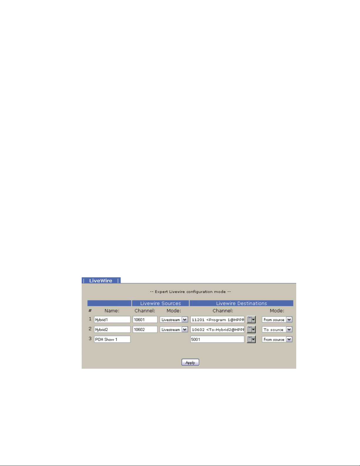
52 | Section 5
5.7 Livewire Audio Troubleshooting
Axia Livewire Audio is very plug and play, but with that plug and play is a little blind faith – unless you know
where to look to troubleshoot when the audio is not working.
The iQ6 provides two audio outputs, or “sources.” (In Livewire parlance, any audio that can be loaded to a
fader or routed to an output is called a Source. Any output is called a Destination.) By plugging the iQ6 into
an approved network switch and following the instructions in the installation chapter, you created these
two sources and made them available to the network. You can route these sources to a destination , like an
Audio Node output, or define them as a source profile on your iQ console.
The iQ6 has three audio “inputs”. The front panel OLED display shows whether audio is present on these
inputs. As mentioned in section 4.2.8, the bottom left corner of the display shows a Livewire logo for a valid
stream, or a circle for a invalid stream. What is a valid stream? A valid stream is a network source that is
actually present on the network. An invalid stream is a network stream that doesn’t currently exist or is not
available to the iQ6. If the caller is not receiving audio or not receiving POH (Program on Hold), check the
state of this indicator first.
Indicator is a circle with a diagonal line (no stream available to input):
POH input: Verify that the POH Livewire channel that has been configured in the Livewire Audio page is
correct. If correct, is that channel enabled on the network? Is there a network disconnection somewhere
that is preventing the stream from reaching the iQ6?
Hybrid inputs (“backfeeds”): By default, the hybrid input will be the “backfeed” to the hybrid. This is a
source that’s dynamically created by your iQ console’s mixing engine. It will only generate this source if
the Hybrid source is loaded to a fader and is configured as a PHONE type. The Axia iQ console requires that
you configure which DSP sources are available to the network - have the backfeeds for the iQ6 hybrids been
allocated to the network?
In the Livewire page, there is a link for Expert Mode. This allows for different assignment to the inputs than
the default backfeed.
In Expert mode, the Livewire Destination section is the input stage to the iQ6. The Channel field is used to
request a Livewire channel from the network. If you don’t know the channel number, use the browse button
and a pop-up screen will populate with all the active channels in the network. The Mode drop down has two
options, “From source” and “To source”. When “From source” is selected, the channel requested is specifically the number in the channel field. For example, channel 11201 might be Program 1 from a console,
which is not a mix minus but the all the audio present on the PGM 1 bus. The “To source” mode specifies
the backfeed. When requesting a backfeed, the channel field must equal the same value as the source itself –
since you are requesting the source that is designed to go “to” Hybrid2 (channel 10602).
Page 61

TECHNICAL DATA AND TROUBLE SHOOTING | 53
So is the backfeed assigned as the hybrid input and has the backfeed been assigned as a network source in the
Axia iQ core? Is something other than the backfeed assigned as an input? Is that available on the network?
Try a different network source by selecting the browse button and selecting a source from the network that
you are familiar with. Does the front display icon change?
Indicator is Livewire logo (but no audio heard by caller):
Can you verify there is audio present in that source? Can you route that same source to an analog output
within your system and determine there is audio there or not?
In cases where you are getting a valid backfeed stream but are not able to get any audio in the backfeed, make
sure you understand the “Feed to source” feature of the Axia iQ console. In a source profile for the hybrid
(source type Phone), there is an option to select the “Feed to source”. By default this is “Auto (Program1 /
Phone)”. The Axia iQ console manual fully covers these options. For the sake of troubleshooting, you might
consider changing this option, or, if you don’t change the option, engage the PHONE assignment button on
the fader that has the audio you expect to be delivered to the caller. Note that this changes based on the ON
or OFF state of the fader that the hybrid is assigned to. (The features of the Feed to source in the iQ manual
explain this).
Page 62

Page 63

SPECIFICATIONS | 55
6
Specifications
General
♦ Interface for connecting three ISDN BRI (S0) or six analog telephone lines to professional studio
equipment. Includes two high-performance digital hybrids and a digital matrix switch.
♦ Audio interface is Livewire Audio-over-IP.
♦ Up to twelve control devices - including VSet phones, VX Producer software instances, and iQ
console Telco controls - may be connected simultaneously.
♦ All control and audio is via network connection.
Processing Functions
General
♦ Telos 3rd-generation adaptive digital hybrids
Send (to caller) Processing
♦ High-pass filter
♦ Frequency shifter
♦ AGC/limiter
♦ Pgm-on-Hold AGC/limiter
♦ Send EQ
♦ Ducking
Receive (from caller) Processing
♦ Low-pass filter
♦ Smart AGC/platform leveler
♦ Noise gate
♦ Telos’ DDEQ (Digital Dynamic Equalization) 3-band adaptive spectral control processor
Page 64

56 | Section 6
Audio
Livewire
♦ Livewire connection for all in/out and POH audio in
Switching Matrix and Conferencing
♦ All-digital audio routing and switching
♦ 6 telephone lines, 2 hybrids, 2 studio inputs, 2 studio outputs, 1 Program-on-Hold input
ISDN Telephone Line Connectivity
Protocol Compatibility:
♦ National ISDN-1 and 2
♦ DMS-100 Custom Functional
♦ AT&T 5ESS Custom Point-to-Point
♦ Euro-ISDN conforming to the NET 3/ETS300 protocol
♦ Q. 931 µ-law
Interface (one of the following):
♦ USA & Canada Integrated NT1 for direct connection to ISDN line via the 2-wire
U-interface (6-position/2-pin RJ-11 connector). 2B1Q line coding.
♦ Worldwide 4-wire S interface (8-position/8-pin RJ-45 connector)
Telephone Coding Modes
♦ µ-Law (ISDN Proto set to Natl I-1, AT&T Custom, Q.931µ-law or DMS Custom)
♦ A-Law (ISDN Proto set to ETS-300)
Analog Telephone Line Connectivity
Universal interface for worldwide application. Programmable loop current, ring signaling, and hookflash
time. Includes caller ID decoding using Bellcore 212 modem standard.
Control Ports
Ethernet 100Base-T
♦ Web server for configuration and software updates
♦ Telnet for command line control and diagnostics
♦ VX Producer server allows up to 12 control devices connect simultaneously
Page 65

| 57
7
Warranty and Application Caution
iQ6 LIMITED WARRANTY
is Warranty covers “the Products, ” which are dened as the various audio equipment, parts,
software and accessories manufactured, sold and/or distributed by TLS Corp.,d/b/a Telos
Systems (hereinafter “Telos Systems”).
With the exception of software-only items, the Products are warranted to be free from defects
in material and workmanship for a period of two years from the date of receipt by the end-user.
Software-only items are warranted to be free from defects in material and workmanship for a
period of 90 days from the date of receipt by the end-user.
is warranty is void if the Product is subject to Acts of God, including (without limitation)
lightning; improper installation or misuse, including (without limitation) the failure to use
telephone and power line surge protection devices; accident; neglect or damage.
EXCEPT FOR THE ABOVE-STATED WARRANTY, TELOS SYSTEMS MAKES NO
WARRANTIES, EXPRESS OR IMPLIED (INCLUDING IMPLIED WARRANTIES OF
MERCHANTABILITY AND FITNESS FOR A PARTICULAR PURPOSE).
In no event will Telos Systems, its employees, agents or authorized dealers be liable for incidental or consequential damages, or for loss, damage, or expense directly or indirectly arising from
the use of any Product or the inability to use any Product either separately or in combination
with other equipment or materials, or from any other cause.
In order to invoke this Warranty, notice of a warranty claim must be received by Telos Systems
within the above-stated warranty period and warranty coverage must be authorized by Telos
Systems. If Telos Systems authorizes the performance of warranty service, the defective Product
must be delivered, shipping prepaid, to: Telos Systems, 1241 Superior Ave., Cleveland, Ohio
44114.
Telos Systems at its option will either repair or replace the Product and such action shall be the
full extent of Telos Systems’ obligation under this Warranty. After the Product is repaired or
replaced, Telos Systems will return it to the party that sent the Product and Telos Systems will
pay for the cost of shipping.
Telos Systems’ authorized dealers are not authorized to assume for Telos Systems any additional
obligations or liabilities in connection with the dealers’ sale of the Products.
 Loading...