

Page 1
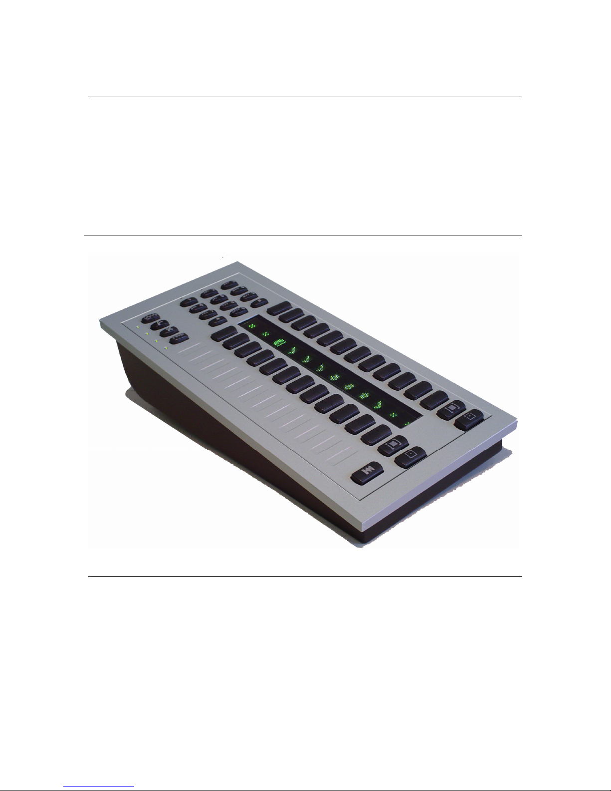
Call Controller
Control Surface for Telos 3rd Generation
Telephone Systems
Manual Version 1.0 for software version 1.0 and later
7 July, 2004
USER’S GUIDE
Page 2

Customer Service
We support you...
By phone/Fax in the USA.
Customer service is available from 9:30 AM to 6:00 PM USA Eastern Time, Monday through Friday at +1
216.241.7225.
Fax: +1 216.241.4103.
By phone/Fax in Europe.
Service is available from Telos Europe in Germany at +49 81 61 42 467.
Fax: +49 81 61 42 402.
By E- Mail.
The address is: support@telos- systems.com.
Via World Wide Web.
http://www.telos- systems.com/
Telos Systems Telos Europe
2101 Superior Avenue Johannisstra βe 6
Cleveland, OH 44114 85354 Freising
USA Germany
+1 (216) 241-7225 +49 81 61 42 467
Fax: +1 (216) 241-4103 Fa x : + 4 9 8 1 6 1 42 4 02
Trademarks
Telos Systems, the Telos logo, Status Symbols, Desktop Director, and Call Controller are trademarks of TLS
Corporation. All other trademarks are the property of their respective holders.
Copyright
Copyright © 2004 by TLS Corporation. Published by Telos Systems, who reserves the right to make
improvements or changes in the products described in this manual, which may affect the product
specifications, or to revise the manual without notice. All rights reserved.
Warranty
This product is covered by a limited warranty, the full text of which is included in your Telos Telephone
Interface Manual.
Service
You must contact Telos before returning any equipment for factory service. Telos Systems will issue a Return
Authorization number, which must be written on the exterior of your shipping container. Please do not
include cables or accessories unless specifically requested by the Technical Support Engineer at Telos. Be sure
to adequately insure your shipment for its replacement value. Packages without proper authorization may be
refused. US customers please contact Telos technical support at +1 (216) 241- 7225. All other customers should
contact your local representative to arrange for service.
We strongly recommend being at the unit when you call, so our Support Engineers can verify information
about your unit and the conditions under which the problem occurs. If the unit must return to Telos, we will
need your serial number, located on the bottom of the unit.
Notices and Cautions
This equipment uses, and can radiate RF energy. For important safety and compliance
information see the notes and cautions sections of your Telos telephone system manual.
Page 3

1 Introducing the Call Controller ™
The Telos Call Controller ™ is intended for use with Telos third- generation Talkshow
Systems such as the TWOx12 ™ and Series 2101 ™. The Call Controller offers similar
functionality to the Telos Desktop Director ™ with a reduced footprint and cost. The call
controller uses an external Telephone for local telephone functions. This telephone
connects to the "Telephone Set" connector of the Call Controller.
Just like the Desktop Director ™, the Call Controller has large buttons and our exclusive
Status Symbol ™ icons, for smooth and easy control of your Talkshow system. And also
like the Desktop Director, it can be operated in either of two modes:
• Producer Mode (Screener) - In this mode the function of the Call Controller is to
switch lines to the attached phone for talking and screening. A line currently on the
attached phone can be dropped, placed on hold (normal hold), or placed on
Screened Hold.
• Talent Mode (on- air line control) - In this mode, the Call Controller is used to place
lines on one of the Talkshow System's two hybrids. The left column of buttons
control the line(s) on the "Caller 1" hybrid, while the right column controls the
line(s) to be placed on the "Caller 2" hybrid.
The current mode is shown by illumination of the appropriate LED at the top of the
Controller.
2 Operation
The basic operation of the Call Controller™ is identical to the operation of the Telos
Desktop Director™, see your Telos Talkshow System manual for details. The biggest
difference is that the functions associated with the Desktop Director's built- in telephone
are, instead, controlled by the telephone attached to the Call Controller; for example,
ringer and handset volume.
A few other functions that required the Desktop Director's LCD screen have been
replaced by keyboard "shortcuts" on the Call Controller's keypad. The system will accept
these keyboard shortcuts only when no lines are selected and the system is idle, to avoid
accidentally placing lines on air, or losing callers. Each Shortcut is a <*> followed by
several digits. The digits used for each shortcut also serve to spell a word, as a mnemonic
to help in recalling the shortcut.
These shortcuts and corresponding mnemonics are outlined below, and are also listed
on the bottom of the Console Director for convenient operator reference.
• Mode Selection - These two commands change between Talent and Producer mode.
The current mode is displayed by two green LEDs near the top of the Call
Controller.
• *77638237 (*PRODUCER)
• *825368 (*TALENT)
• Unit ID - When software, such as Assistant Producer 3.5, is used to control the
functions of a Call Controller the user must know the current system ID for that Call
Controller. This ID number generally does not change, however it may change if the
system is reconfigured, or Call Controllers (or other system control surfaces) are
moved between systems. To view the current ID use the following shortcut:
Page 4

• *33 (*DD)
• Show Selection - Some dual hybrid interface units can be operated in a dual studio
mode, where the two hybrids are used independently in two studios. In these cases
Desktop Directors may choose from "Show 1" (hybrid 1) or "Show 2" (hybrid 2). If
your system is configured for one of the dual modes you can use the following
shortcuts to change the Show being controlled by a specific Call Controller:
• *74691 (*SHOW1)
• *74692 (*SHOW2)
NOTE: When the Call Controller is used with the Series 2101 it cannot choose a
show. However, a Desktop Director can be used to select the show being used on
that 2101 Studio Interface, and all Call Controllers, Console Directors and Desktop
Directors connected to that Studio Interface will, of course, be associated with that
show as well.
3 Connections
Connecting the Call Controller to your Telos Talkshow system is identical to connecting
a Desktop Director, as covered in your Telos Talkshow system manual. This jack is
labeled Telos Interface and the connection is made using an 8-pin miniature modular
cable (RJ- 45 style) provided with the unit. An LED adjacent to this jack will illuminate
continuously if the connection is correct.
In cases where two Telos control units share the same Desktop Director port on the
Talkshow system, one unit will need to have its termination resistors disabled (units are
shipped with the terminators enabled). To do so, remove the unit's cover by removing
the screws around the edge of the black metal cover. Inside locate two 3- pin headers,
labeled "JP- 1" and "JP- 2" and move the jumper blocks top the alternate positions for
both jumpers. Replace the cover and screws.
The connection to the telephone set is made using a standard 6- position 2- pin
miniature modular cable (RJ- 11 style) to the jack on the unit labeled Telephone Set. The
center two pins are used. If your Telephone does not use this type of connector an
adaptor may be purchased locally.
4 Telephone Set Interface
Most analog telephone sets intended for use with standard analog "POTS" line will work
with the Call Controller for basic operation. The "Telephone Set" jack provides a signal
that emulates a USA analog telephone line as follows (for more detailed information see
TIA/EIA- 464- B):
Loop Specifications: Loop Current - 25 mA
Loop Voltage - 48 VDC
Ringer Specifications: Configuration - Metallic (line to line)
Voltage/Frequency - 20 Hz/ 51 Volts RMS (Sine)
Max Ringer Equivalence - 2 REN
 Loading...