

Page 1

TELEMETRY-ELECTRONICS CONSULTANTS
932 E. IMPALA AVENUE y MESA, ARIZONA 85204-6699 U.S.A.
TEL (480) 892-4444 y FAX (480) 892-9139
E-MAIL info@telonics.com
www.telonics.com
Model SST-901M
Spread Spectrum Radio Modem
User’s Guide
PB008896 Rev A 2011.09.13
Copyright Notice
Copyright © 2011 Telonics, Inc.
All Rights Reserved.
No part of this publication may be copied without the express written permission of Telonics, Inc.,
932 E. Impala Ave., Mesa, AZ 85204.
Page 2

TABLE OF CONTENTS
1.0 Notice to United States Users................................................................................................. 3
2.0 Notice to Canadian Users .......................................................................................................3
3.0 Hardware Setup........................................................................................................................ 4
4.0 Telonics Data Converter (TDC)............................................................................................... 6
4.1 Quick Start Guide................................................................................................................... 6
4.2 SST Unit and Session Settings Window ................................................................................ 8
4.3 SST Transfer Session Window ............................................................................................ 11
4.4 Main Window (SST) ............................................................................................................. 13
5.0 SST-901M SPECIFICATIONS................................................................................................. 15
PB008896 Rev A
Page 2 of 15
Page 3

Model SST-901M Spread Spectrum Radio Modem User’s Guide
1.0 Notice to United States Users
This device complies with Part 15 of the FCC Rules. Operation is subject to the following two conditions:
(1) this device may not cause harmful interference, and (2) this device must accept any interference
received, including interference that may cause undesirable operation. In normal operation the unit and
approved antenna is positioned several feet from the user but under no circumstance should the antenna
be positioned less than 20 cm from the operator.
The user is cautioned that changes or modifications not expressly approved by Telonics could void the
user’s authority to operate the equipment. This restriction includes the use of specified antennas which
have been certified for use with the SST-901M. See Antenna Configurations section below.
2.0 Notice to Canadian Users
Under Industry Canada regulations, this radio transmitter may only operate using an antenna of a type and
maximum (or lesser) gain approved for the transmitter by Industry Canada. To reduce potential radio
interference to other users, the antenna type and its gain should be so chosen that the equivalent
isotropically radiated power (e.i.r.p.) is not more than that necessary for successful communication.
The SST-901M (IC: 4610A-SST901M) has been approved by Industry Canada to operate with the antenna
types listed below with the maximum permissible gain and required antenna impedance for each antenna
type indicated. Antenna types not included in this list, having a gain greater than the maximum gain
indicated for that type, are strictly prohibited for use with this device.
Approved Antenna Type Telonics P/N Max Gain Required Impedance
Collinear Vertical w/ ground plane CM007724-900 7.2dBi 50Ω
Collinear Vertical w/ ground plane CM008828-900 5.4dBi 50Ω
Aircraft Blade Antenna CM007462-001 4.0dBi 50Ω
This device complies with Industry Canada license-exempt RSS standard(s). Operation is subject to the
following two conditions: (1) this device may not cause interference, and (2) this device must accept any
interference, including interference that may cause undesired operation of the device.
Le présent appareil est conforme aux CNR d'Industrie Canada applicables aux appareils radio exempts de
licence. L'exploitation est autorisée aux deux conditions suivantes : (1) l'appareil ne doit pas produire de
brouillage, et (2) l'utilisateur de l'appareil doit accepter tout brouillage radioélectrique subi, même si le
brouillage est susceptible d'en compromettre le fonctionnement.
PB008896 Rev A
Page 3 of 15
Page 4
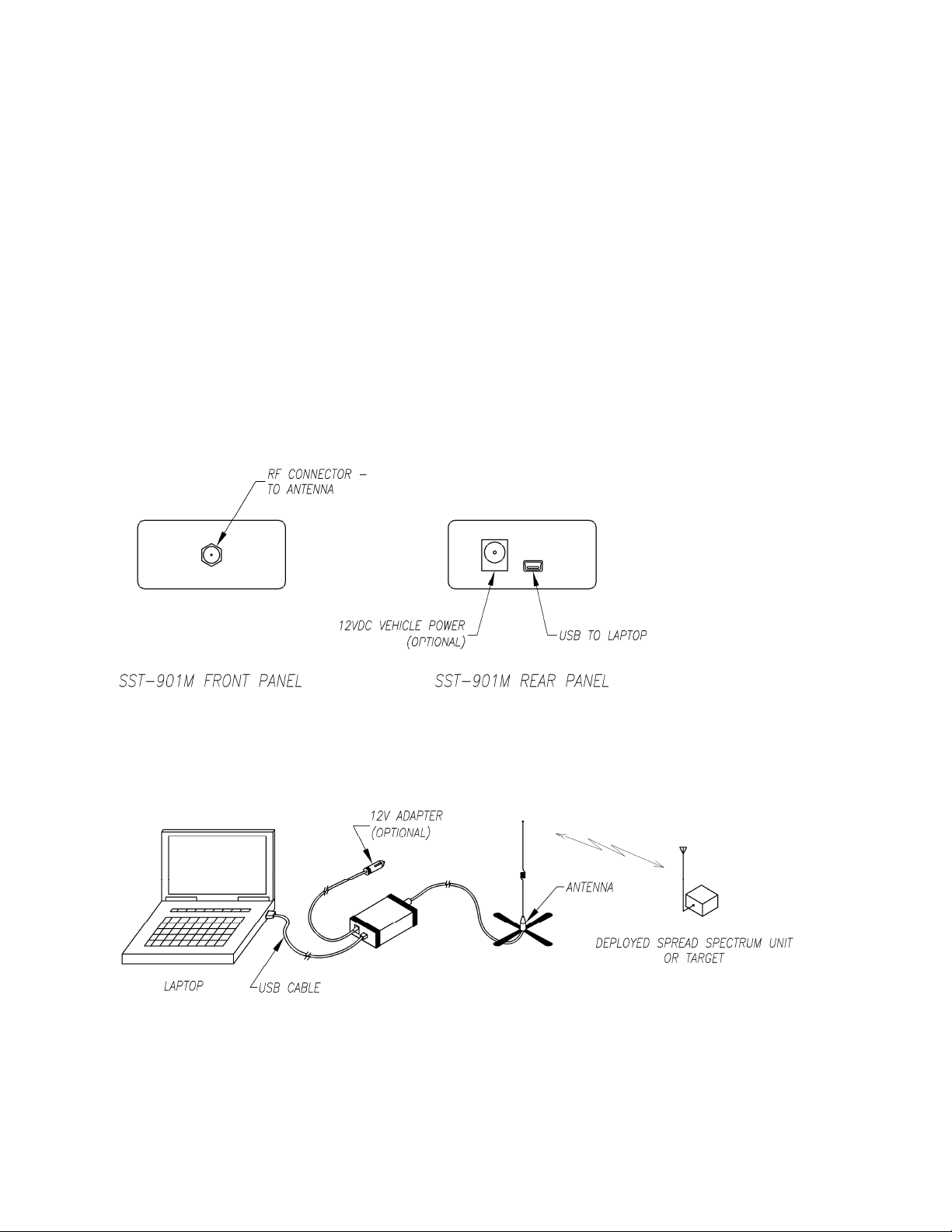
3.0 Hardware Setup
The SST-901M is a portable radio modem allowing field data transfer from a deployed Spread Spectrum
Unit to a portable laptop computer. Before the system will function properly, the SST-901M must be
properly connected to a laptop computer and an antenna. There are three connectors on the SST-901M.
Their function and proper connection are described below and diagrammed in figures 1 and 2:
1. RF connector: Connect this jack to the external antenna with the supplied coaxial cable assembly.
See the Antenna configurations section for more information about approved antennas and cabling.
2. USB Jack: Connect the SST-901M to the laptop computer with the supplied USB cable. The unit
derives power from the laptop via the USB cable.
3. External Power Jack (optional): The SST-901M is normally powered by the laptop via the USB cable.
When the radio link is in use, the laptop battery will be depleted much faster than normal. Laptop
battery life can be extended by connecting the optional 12V Auto Charge Cord (Telonics P/N
PS000338-001) to the external power jack. Note that the charge cord only supplies power to the SST901M – it does not supply power to the laptop computer.
Figure 1 – SST-901M Front and Rear Panel Connections
Figure 2 – SST-901M Typical Installation
PB008896 Rev A
Page 4 of 15
Page 5
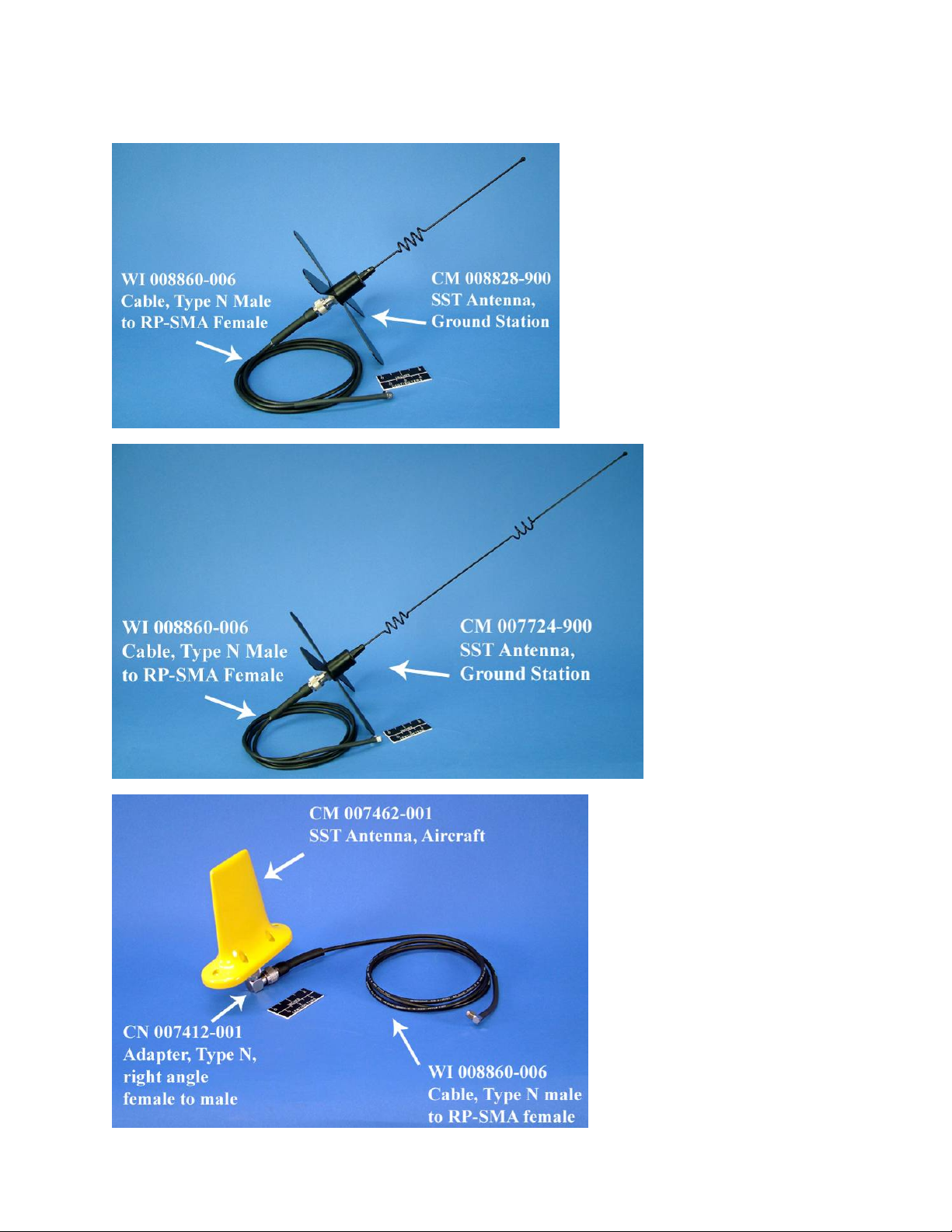
The following antennas have been specifically designated and certified for use with the SST-901M. Use of
other antennas voids the user’s authority to operate the equipment.
PB008896 Rev A
Page 5 of 15
Page 6

4.0 Telonics Data Converter (TDC)
Telonics Data Converter (TDC) is the software user-interface that controls the SST-901M RF Modem to
download data over the spread-spectrum link. TDC can manage the RF connection settings for each
deployed SST unit allowing users to download data from units in the field with minimal interaction. In
addition to downloading log memory, TDC also provides the ability to test the RF link, download diagnostic
information, initiate a blackout period to save battery life, and convert downloaded data into standard CSV
reports. TDC is compatible with any PC with an available USB port running Windows 2000 or newer,
including many ultra-mobile PCs and tablet PCs.
4.1 Quick Start Guide
Enter your Authorization Code(s)
The first step to using TDC is to download the utility from the Telonics website. The utility is immediately
useable in the evaluation or demonstration mode. In evaluation mode you will not be able to download SST
data, download datalogs, or generate reports. This demonstration mode allows you to evaluate TDC and
see how you will use TDC during your study. In order for TDC to be fully functional, you must purchase a
license. Contact Telonics with your purchase order or credit card information to obtain your Authorization
Code. The Authorization Code can be provided to you over the phone, by FAX, email, or postal mail.
Once you have obtained your Authorization Code(s) from Telonics, select the "About Telonics Data
Converter" choice under the "Help" menu in TDC. Click the "Add..." button. Enter your Authorization Code
and press the "OK" button. If you were given more than one Authorization Code, press the "Add..." button
again and repeat for each remaining Authorization Code.
For additional information see the Authorization Codes section of help.
Set your Options
TDC must be configured for use. From the Options Menu, select "File Locations..." to view the Options
Window. Set your preferred directory for spread-spectrum files and your report destination folder by typing
the full path in the provided field. The spread-spectrum files directory will hold all of the data that you
downloaded over the SST link (e.g. TSF files, statistics files, diagnostic information). The report directory
will hold your final converted reports. You can also select a directory by pressing the "Browse" button next
to the field. From the Options Window, you can view different groups of options by clicking the tabs near
the top of the window. Once you have finished adjusting the program options, press the "OK" button to
save your changes.
For additional information see the Options section of help
Import or Add SST Units
TDC uses TPF files that describe the unit’s identity and operational behavior. These files are typically
provided to you as attachments in an email from Telonics. From the SST tab in the Main Window, press
the "Configure unit and session settings" link or alternatively select "Unit & Session Settings..." from the
"Spread Spectrum" menu to launch the Spread Spectrum Unit & Session Settings Window. From this
window, press the "Import..." button and then browse to the TPF file that was used to program your SST
units. TDC will then import the connection settings for each unit in that TPF file.
If you do not have a TPF file for the units, you can also add units by selecting "[Add new unit]" from the list
of units and then manually type in the connection settings.
Specify Tasks to Perform in Next SST Transfer Session
From the Spread Spectrum Unit & Session Settings Window, select an SST unit from the list. The "Next
Transfer Session" section of the window lists all optional tasks that you can perform during the next SST
PB008896 Rev A
Page 6 of 15
Page 7

session with the selected unit. Be sure to specify the tasks for each unit to which you plan to connect.
Consider planning and selecting these tasks ahead of time (in the office) before heading out to download
data in the field.
When you are finished importing SST units and selecting tasks for the next transfer session, press the OK
button to close the Spread Spectrum Unit & Session Settings Window and save your changes. For
additional information see the SST Unit and Session Settings section of help.
Download SST Data
Connect the SST-901M to the PC using the supplied USB cable. Note that the first time you connect the
SST-901M you may be prompted to install a driver. See the USB Driver Installation section of help if you
need assistance installing the USB driver. Connect the antenna to SST-901M. Specific antennas have
been approved for use in ground monitoring applications and for use in aircraft monitoring. When testing
the spread-spectrum link, separate the SST-901M and the units under test by at least 20 meters.
To begin the download test remove the magnet prior to attempting communications. Once you remove the
magnet, the unit will enter a predeployment period (typically 4 hours) in which you will be able to conduct
SST transfer sessions. During predeployment, the unit will also collect GPS and/or QFP locations (typically
once an hour). When the unit is actively trying to collect a GPS or QFP location, you will not be able to
conduct an SST session.
From the SST tab in the Main Window, press the "Download file over spread-spectrum link" hyperlink or
select "Transfer Session..." from the "Spread Spectrum" menu to launch the Spread Spectrum Transfer
Session Window. Select a unit from the list and press the Connect button. TDC will attempt to connect to
the unit and complete the tasks that you have previously specified for this unit. If TDC has stored a TPF tile
for the selected unit, the SST Active field will tell you the next time the selected unit is scheduled to listen
for SST communications.
During an SST transfer session, the window displays progress for each task and the signal strength and
transfer rate of the link. After completing an SST session, TDC displays a message indicating whether the
session was successful. If the session was successful, TDC updates the Results tabs to show information
about the results of the last transfer session. The "Downloaded Data" tab shows the name of the file that
contains your downloaded data (including GPS/QFP locations). See the next step for instructions on
converting this .tsf file into a report. If the session failed, please try to connect to the unit again.
For additional information see the SST Transfer Session section of help.
Convert SST Data (.tsf file)
The file that is downloaded from the unit under test is not in a readable form and it is necessary to convert
the recovered file. From the Spread Spectrum Unit & Session Settings Window, select the unit for which
you would like to convert data (if you have not already done so). The "Downloaded Data" tab will list the
SST file (.tsf) that you downloaded during the last SST transfer session with that unit. Click the filename of
the downloaded file and TDC will offer to convert the file. The Main Window displays conversion progress
in the Results field of the SST tab. After TDC has finished converting the file, the Results field displays the
name of the generated report. For detailed conversion instructions, see the Main Window (SST) section of
help.
Note that you can also select the SST data to convert from the Main Window in TDC. Select the SST tab
and then press the "Select File..." button. Browse to the SST file (.tsf) that you would like to convert. Note
that TDC downloads all SST files to the spread-spectrum files directory that you specified in the File
Locations tab of the Options Window. TDC automatically names the files to include the CTN of the unit and
date/time of the SST session.
After converting the SST file (.tsf), TDC stores the final report (.csv file) in the reports directory that you
specified in the File Locations tab of the Options Window.
If your unit supports QFP locations, be sure that your PC is connected to the Internet when you convert the
data (.tsf file). You do not need an Internet connection to download the SST data.
PB008896 Rev A
Page 7 of 15
Page 8

4.2 SST Unit and Session Settings Window
The SST Unit and Session Settings Window allows you to perform the following tasks:
• Import new SST units from a TPF file
• Delete an existing SST unit
• Add a new SST unit by manually specifying connection settings
• Update connection settings and assign a comment to a unit
• Specify the tasks to perform during the next SST transfer session
Unit Selection
The left section of this window lists all SST units known to TDC. To select a unit, click on that unit in the list.
To add a new unit manually, select the last entry in the list ("[Add New Unit]") and then type in the
connection parameters in the upper-right section of the window.
Import Button
Press the Import Button to add new SST units from a TPF file. TDC prompts you to select the TPF file.
Note that this window manages only SST units, so TDC will not find any units if you select a TPF file for a
store-on-board.
Delete Button
Press the Delete Button to delete the currently selected SST unit from TDC. If you have previously had an
SST transfer session with the selected unit, TDC displays a warning message before deleting the unit so
that you have an opportunity to cancel the deletion. The Delete Button is disabled when "[Add New Unit]" is
selected.
PB008896 Rev A
Page 8 of 15
Page 9

Unit
The Unit group is located in the upper-right section of this window. It lists the connection settings for the
currently selected unit.
Telonics CTN
The CTN uniquely identifies the unit. TDC uses the CTN during the connection process of an SST session.
TDC also uses the CTN to name the files downloaded during an SST transfer session.
Comment
The Comment field allows you to assign a comment to the selected unit. Using the Comment field allows
you to assign a unit name that you can easily identify later. This is particularly useful when you have
several SST units listed in TDC.
Password
The Password field specifies the connection password for the unit. If the unit does not have a password,
leave this field blank.
Frequency Set
The Frequency Set field specifies the frequency set that will be used for communication between the SST901M and the remote units. Each set consists of 50 separate frequencies, nominally spaced at 102 kHz
intervals. Frequency Set limits are listed in Section 5.0 of this document.
The choice of which frequency set(s) to use is left to the discretion of the Telonics SST system user. The
decision of which set(s) to use must be made before the study begins so that remote units can be
programmed appropriately prior to deployment. The paragraphs below provide information that may aid in
the decision of which frequency set(s) to use for a given study:
• In studies involving multiple deployed (remote) units, all units in close proximity on a given frequency
set will be aware that communications are occurring. Only the SST-901M and the addressed remote
unit will be involved in the communication, however all units that can hear the communication will
repeatedly spend small amounts of energy receiving and decoding the communication packets only
to discover that they are not involved in the communication. By using multiple frequency sets, this
unnecessary energy expense in the remote units can be reduced (extending operational life).
• There is a known source of interference in the area and it is severe enough to prevent successful
communications.
• There are multiple studies being run in close proximity and two or more SST-901M units may be in
use at the same time.
• Operation of the SST-901M and associated remote units is causing harmful interference in the proper
operation of some other system or equipment.
Coding
The Coding field specifies the coding type for the unit. For now, SST units support only one coding type so
this field is disabled.
Update from TPF File Link
Clicking this hyperlink lets you update the connection settings (password, frequency set, and coding) for
the currently selected unit. Clicking this link does not cause TDC to import new units or update the
connection settings for other units listed in the TPF file.
PB008896 Rev A
Page 9 of 15
Page 10

Next Transfer Session
The Next Transfer Session group is located in the lower-right section of this window. It specifies the action
to perform during the next SST transfer session.
Download Data
This setting specifies whether to download all data, new data, by date range, or not to download any data
from the unit.
Download Test File
Use this setting to download a test file. The drop-down list lets you specify the size of the test file.
Downloading a test file is useful for testing the performance (range, transfer rate, and signal strength) of the
spread-spectrum link.
Factory Diagnostic Data
Use this setting if you are experiencing problems with the unit and Telonics instructs you to download
diagnostic data. You will then need to send your data file (TSF) to Telonics for analysis.
Acquire New GPS Position
Use this setting to instruct the unit to acquire a new GPS position. TDC will then wait for the unit to acquire
the new GPS position, reconnect to the unit, and download the updated position. Depending on how long
the unit takes to acquire the GPS fix, this task may add up to 5 minutes to the SST transfer session.
Please note that this feature is “grayed out” (not available) in the initial release of the Telonics SST system.
Blackout Period: SST Communications After Session
This energy-saving feature instructs the unit to black out SST communications after the transfer session is
complete. TDC displays the duration of the blackout period if that information is available. Otherwise, see
the TPF record for the blackout duration.
Transfer TPF File
Use this setting to download the TPF File from the unit.
SST Active Time
The bottom of the window displays the next active time (in UTC) for SST communications if that information
is available. The active time for SST communications accounts for the SST schedule and a blackout period
that you may have established during your last transfer session.
OK Button
Pressing the OK Button saves any changes that you made within this window.
Cancel Button
This button closes this window without saving your changes. TDC displays a warning message before
dropping the changes that you made, giving you a final chance to save your changes.
PB008896 Rev A
Page 10 of 15
Page 11

4.3 SST Transfer Session Window
This program window provides the ability to initiate an SST transfer session, view the status of the current
SST transfer session, and view the results from previous transfer sessions.
Unit
The Unit drop-down list allows you to select the unit for the SST transfer session. The results tabs display
the results from the last successful transfer session for the selected unit.
Settings
The Settings button opens the SST Unit and Session Settings Window.
Last Attempt
This field displays the time (in UTC) that you last attempted a transfer session with the selected unit. This
time is updated as soon as you press the Connect button.
Transfer Time
This field displays the time (in UTC) of your last successful transfer session with the selected unit. This time
is updated after a successful session.
SST Active
This field displays the next time (in UTC) that the unit is scheduled to listen for SST communications. This
time accounts for the SST schedule and a blackout period that you may have established during your last
transfer session.
PB008896 Rev A
Page 11 of 15
Page 12

Results
These tabs display the results from the last successful transfer session. Files listed in the results section are
located in your Spread-Spectrum Files directory (set in the File Locations tab of the Options Window). You
can access these files from this window by clicking the filename or icon. The results section includes the
following tabs:
• Downloaded Data
The File field lists the downloaded data file (TSF), factory-diagnostic data (optionally included inside
TSF), and the test file. The Successful and Failed fields summarize the number of fixes included in the
downloaded data file. Download Size describes the number of bytes downloaded for the data file (TSF).
Download Type displays the selected options for the data download.
• Current Location
This tab displays information from the most-recent successful GPS fix. TDC downloads this
information with every SST transfer session. You can optionally instruct the unit to "Acquire a new
GPS fix" as part of the SST session (see SST Unit and Session Settings Window).
• Blackout period
Start Time displays the scheduled start of the SST blackout period , accounting for a short grace
period after the last SST transfer session. End Time displays the end of the blackout period. The End
Time does not account for on/off periods in the SST schedule. If the End Time is in the middle of an
off period the unit will not listen for SST communications until the start of the next scheduled on
period. See the SST Active field to see the next time that unit will listen for SST communications.
• Transfer TPF
The Type field specifies whether TDC downloaded or uploaded a TPF file. The Size field describes
the number of bytes transferred for the TPF file. The File field lists the name of the transferred TPF
file.
• Stats
The Statistics tab summarizes the health of the spread-spectrum link in the most-recent SST transfer
session. Avg Signal displays the average signal strength of packets received by the SST-901M.
Session Duration displays the total length of the transfer session. Tx Rate shows the average
transfer rate for sending and receiving files over the spread-spectrum link. The Bytes Received and
Sent fields describe the total number of bytes transferred by the SST-901M during the transfer
session. The File field lists the detailed statistics file, which includes additional statistics about the
spread-spectrum link.
• Debug
The File field lists the Debug and Packet files. Debug Info displays the contents of the Debug file. If
you are experiencing difficulties with SST communications, Telonics may ask you to send these files
to the factory for analysis.
Connect Button
Press the Connect Button to attempt to connect to the selected unit and conduct an SST transfer session.
Stop Button
Press the Stop button to cancel a transfer session. If Telonics Data Converter has connected to the unit and
is in the middle of the transfer session, TDC will warn you before canceling the session. If TDC has not yet
connected to the unit, TDC cancels the session without warning.
Close Button
Pressing the Close Button closes this SST Transfer Session Window. If TDC is in the middle of an SST
session, TDC will give you a warning and cancel the session before closing the window.
PB008896 Rev A
Page 12 of 15
Page 13

4.4 Main Window (SST)
The Main Window consists of two separate tabs. To switch to a different tab, click on the name of the tab
near the top of the Main Window. This Help page covers the SST Files tab within the Main Window.
Main Menu
Like most applications, the Main Menu in TDC is located at the very top of the Main Window. Choices
within the Main Menu allow TDC to perform the following actions:
• Convert Data (File->Convert Data)
• Exit TDC (File->Exit)
• Open the Options Window (Options->File Locations, Options->Report Settings, Options->Data
Formats, or Options->Program Operation)
• Open a Download Datalog Window (Smart Cable->Download Datalog...)
• Open a Download TPF File Window (Smart Cable->Download TPF File...)
• Open the Erase Datalog Window (Smart Cable->Erase Datalog...)
• Open the SST Transfer Session Window (Spread Spectrum->Transfer Session...)
• Open the SST Unit and Session Settings Window (Spread Spectrum->Unit & Session Settings...)
• Access the TDC help system (Help->Contents, Help->Index, or Help->Search)
• Open the About TDC Window (Help->About Telonics Data Converter)
Spread Spectrum Communication
The Spread Spectrum Communication box is located near the top of the Main Window. This box provides
links to download data and configure communication settings.
PB008896 Rev A
Page 13 of 15
Page 14

Download file over spread-spectrum link
Click this link to open the SST Transfer Session Window. From that window, you can download data from a
unit over the spread-spectrum link. If you have already downloaded the SST file, simply use the Convert
File box to select and convert the file.
Configure unit and session settings
Click this link to open the SST Unit and Session Settings Window. From that window, you can specify the
connection parameters for an SST transmitter and choose the options for the next SST transfer session.
Convert File
The Convert File box allows you to select an SST file. This box displays the selected file, information about
that file, and results of the conversion.
Select File...
Pressing the Select File Button allows you to browse your PC and select an SST file for processing. This
button is disabled when TDC is in the process of converting data. TDC displays the currently selected file
next to the Select File Button.
Unit
This field identifies the transmitter that created the selected spread-spectrum file. This information is
extracted from inside the spread-spectrum file (.tsf). This field also displays any comments that have been
assigned to SST units.
Results
Telonics Data Converter uses this field to inform you of its progress while it converts the file. After the
conversion is finished, this field will contain the name of the generated reports (or state that an error
occurred). Click the name or icon of a report listed in the results field to open the CSV or Google Earth file.
Convert Button
Pressing the Convert Button causes TDC to start converting the spread-spectrum file.
Stop Button
Pressing the Stop Button causes TDC to stop converting the file. You cannot resume a data conversion
once it has been canceled.
Exit Button
Pressing the Exit Button causes TDC to close all windows and exit. If TDC is converting data when you
press the exit button, you will be given a chance to cancel your request to exit.
PB008896 Rev A
Page 14 of 15
Page 15

5.0 SST-901M SPECIFICATIONS
GENERAL
FCC ID JYLSST901M
Frequency Range 902.102 - 927.908 MHz.
Spread Spectrum Type Frequency Hopping FSK
Applicable FCC Rules Part 15 (15.247)
Number of RF Frequency Sets 4 sets, non overlapping
Set 1: 902.102 - 907.100 MHz
Set 2: 908.120 - 913.220 MHz
Set 3: 915.260 - 920.360 MHz
Set 4: 922.808 - 927.908 MHz
Nominal Channel Frequency Spacing 102 kHz
Data Interface USB
POWER REQUIREMENTS
Primary Supply (USB Power) 5.0 V
Auxiliary Supply (Optional Auto/Aircraft Power) 10-16 Vdc
Transmit Current 400 mA typ @ 5V
250 mA typ @ 12V
Receive Current 30 mA typ @ 5V
Stand-by Current < 5 mA
TRANSMITTER
Power Output 500 mW (+27dBm)
Frequency Stability ± 0.5 ppm @ 25˚C
± 1.0ppm -30<T<+60˚C
Modulation Data Rate 19.2 kbps
Modulation Type FSK
Modulation Bandwidth (99%) 40 kHz typ
Load Impedance 50 Ω
RECEIVER
Noise Figure <3.0 dB
Sensitivity for 10
MECHANICAL / ENVIRONMENTAL
Dimensions, excluding RF connector 3.40” l x 2.25” w x 1.0” h
86 x 57 x 25 mm
Operating Temperature Range -30 to +70 ˚C
Humidity <95%, non-condensing
-4
BER @ 19.2 kbps <-110 dBm typ
PB008896 Rev A
Page 15 of 15
 Loading...